
Abstract
Externally bonded Fibre Reinforced Polymer (FRP) confinement is extensively used to improve the bond strength of substandard lap spliced steel bars embedded in reinforced concrete (RC) components. However, the test results from bond tests on such bond-deficient components are not fully conclusive, which is reflected in the few design guidelines available for FRP strengthening. For the first time, this article presents a comprehensive survey on FRP strengthening of substandard lap-spliced RC members, with emphasis on the adopted experimental methodologies and analytical approaches developed to assess the effectiveness of FRP in controlling bond-splitting failures. The main findings and shortcomings of previous investigations are critically discussed and further research needs are identified. This review contributes towards the harmonisation of testing procedures so as to facilitate the development of more accurate predictive models, thus leading to more cost-effective strengthening interventions.
Introduction
Since the 1994 Northridge and 1995 Hyogoken-Nanbu (Kobe) earthquakes, externally bonded fibre-reinforced polymers (FRPs) have been widely used for the local strengthening of substandard lap-spliced regions of reinforced concrete (RC) columns of bridges and buildings. Typical applications involve bonding FRP fabric sheets or precured shells around a column to provide additional confinement (see Figure 1(a)), thus enhancing the lap bond strength and preventing a premature splitting failure. In the last decades, extensive experimental research has confirmed the effectiveness of FRP confinement in improving the behaviour of RC members with inadequate short lapped bars (Aboutaha et al., 1996; Bournas and Triantafillou, 2011; Bousias et al., 2006; ElGawady et al., 2010; Ghosh and Sheikh, 2007; Harajli and Dagher, 2008; Harries et al., 2006; Saadatmanesh et al., 1996, 1997b; Seible et al., 1997; Tastani and Pantazopoulou, 2010). Due to the large number of parameters affecting the bond behaviour of lapped bars, different experimental and analytical approaches were adopted to evaluate the effectiveness of FRP confinement. In general, however, two experimental approaches are mainly implemented:
Capacity–ductility approach. The tests in these pioneering studies aim at assessing the enhancement in capacity and/or ductility of columns provided by the FRP confinement. Based on these experiments, some analytical models were proposed to compute the thickness of FRP required to prevent lap splice failure (e.g. Elnabelsy and Saatcioglu, 2004; Elsanadedy and Haroun, 2005; Hawkins et al., 2000; Seible et al., 1997).
Bond strength approach. The bond strength enhancement provided by FRP reinforcement is examined using test specimens recommended in state-of-the-art reports on bond (e.g. fib Bulletin 10 (2000) or ACI 408 (2012)) including pullout, beam-end and beam specimens. The contribution of the FRP reinforcement is evaluated from the increase in the observed bond strength.
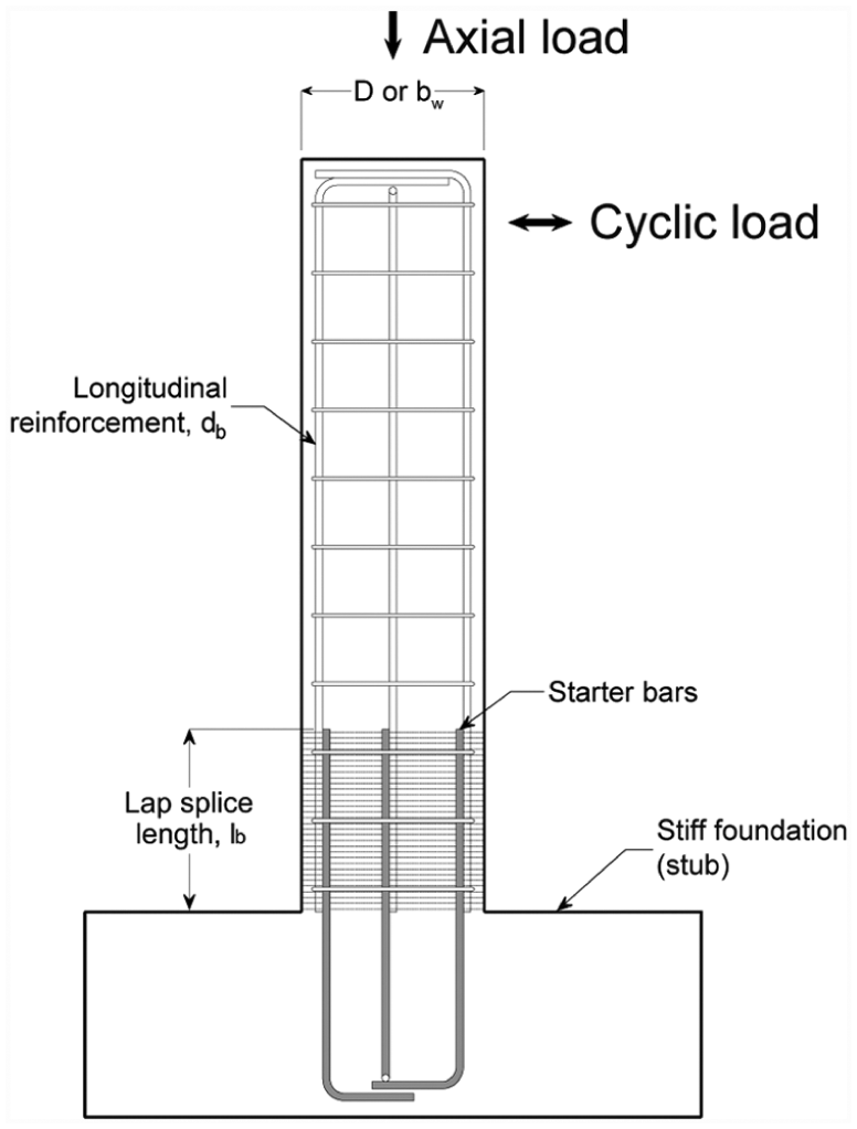
FRP confinement around a lap-spliced cantilever column specimen.
Despite the extensive research, the majority of the previous studies focused on lap-spliced circular columns. Conversely, less research has been carried out to investigate the effectiveness of FRP as a strengthening solution for substandard rectangular members of RC buildings, and only a few existing guidelines (AIJ 2002, BSI 2005, TEC 2007, CNR 2012, EPPO 2012) address these issues.
This article presents a comprehensive literature review on substandard lap-spliced RC members strengthened with externally bonded FRP. Special emphasis is placed on the experimental methodology and analytical approaches adopted to study the effectiveness of this strengthening method. Conflicting research findings and aspects requiring further research are discussed and commented upon. This article contributes towards the harmonisation of testing and assessment procedures in a timely manner as current European guidelines (e.g. fib Bulletin 14 (2001) and Eurocode 8 Part 3 (2005)) are currently under revision and both of them are envisaged to adopt bond strength approaches for the FRP strengthening of laps.
Assessment of FRP reinforcement effectiveness through testing
The experimental methodologies used to assess the effectiveness of external FRP reinforcement on lap-spliced RC members can be classified according to the capacity–ductility and bond strength approaches described before.
Capacity–ductility approach: tests on cantilever columns
Cantilever columns have been extensively tested in the past (Bournas and Triantafillou, 2011; Bousias et al., 2006, 2007; Breña and Schlick, 2007; Chang et al., 2000, 2001; Chung et al., 2008; ElGawady et al., 2010; Elnabelsy and Saatcioglu, 2004; Eshghi and Zanjanizadeh, 2008; Harajli, 2008; Haroun and Elsanadedy, 2005; Haroun et al., 1999, 2003; Kim et al., 2011; Ma et al., 2000; Ma and Xiao, 1999; Priestley et al., 1992; Priestley and Seible, 1995; Saadatmanesh et al., 1996, 1997a, 1997b; Saatcioglu and Elnabelsy, 2001; Sause et al., 2004; Schlick and Breña, 2004; Seible et al., 1997; Xiao and Ma, 1997; Yalçin and Kaya, 2004; Youm et al., 2007). Column specimens are usually cast on a stiff concrete block simulating the structure’s foundation, as shown in Figure 1. The longitudinal column reinforcement is lapped at the base for typical short lengths lb ≈ 20–30db (where db = bar diameter) to replicate old construction practices and to promote bond splitting failure. Columns are commonly tested in vertical position by applying increasing quasi-static cyclic lateral loads or displacements, although horizontal specimens have been also tested (Ghosh and Sheikh, 2007; Harajli and Rteil, 2004; Ilki et al., 2004; Thermou and Pantazopoulou, 2009). A constant axial load is usually applied to the column, but columns with no axial load have been also tested (ElSouri and Harajli, 2011; Harajli and Dagher, 2008; Harajli and Khalil, 2008; Kim et al., 2011). The effectiveness of the FRP strengthening is assessed by comparing the results of the original ‘as-built’ and FRP-strengthened columns in terms of enhancements in capacity, ductility and energy dissipation (hysteresis loops).
As expected, unstrengthened ‘as-built’ columns failed prematurely due to splitting of the concrete cover around the lapped bars, leading to a rapid strength and stiffness degradation. Comparatively, the FRP-confined columns generally failed in a ductile manner by yielding of the lapped bars, accompanied by partial splitting (i.e. less severe cracking), bar pullout or bar buckling. While all studies reported significant enhancements in the capacity and ductility of the strengthened columns, the magnitude of the enfacement varies considerably from one study to another given the different geometries and test conditions adopted.
Bond strength approach
Specimens tested using this approach provide insight into the basic behaviour of anchorages and lap splices in FRP-strengthened members. In general, the unstrengthened specimens are designed to fail prematurely by cover splitting. Short bonded lengths are commonly selected to produce a uniform distribution of bond force along the bars and to prevent bar yielding. The effectiveness of the strengthening is evaluated by comparing the bond strength of unstrengthened and FRP-strengthened specimens, as well as load–deflection and/or bond stress–bar slip relationships.
‘Pullout’ tests
Kono et al. (1997, 1999, 2000) tested ‘Schmidt-Thrö’ pullout specimens with a single- or four-anchored bar as shown in Figure 2(a), (b), (d) and (e). A vertical slot defined the bonded length at the end of the specimens (lb = 4–12db or 100–300 mm) and prevented the application of compression forces in the concrete around the bar. The use of a single layer of carbon FRP (CFRP) fabric across the anchorage length led to a more ductile pullout failure and enhanced the bar bond strength by an average of 80%. Kono et al. concluded that the bond strength enhancement was independent of the bonded length of the bar.
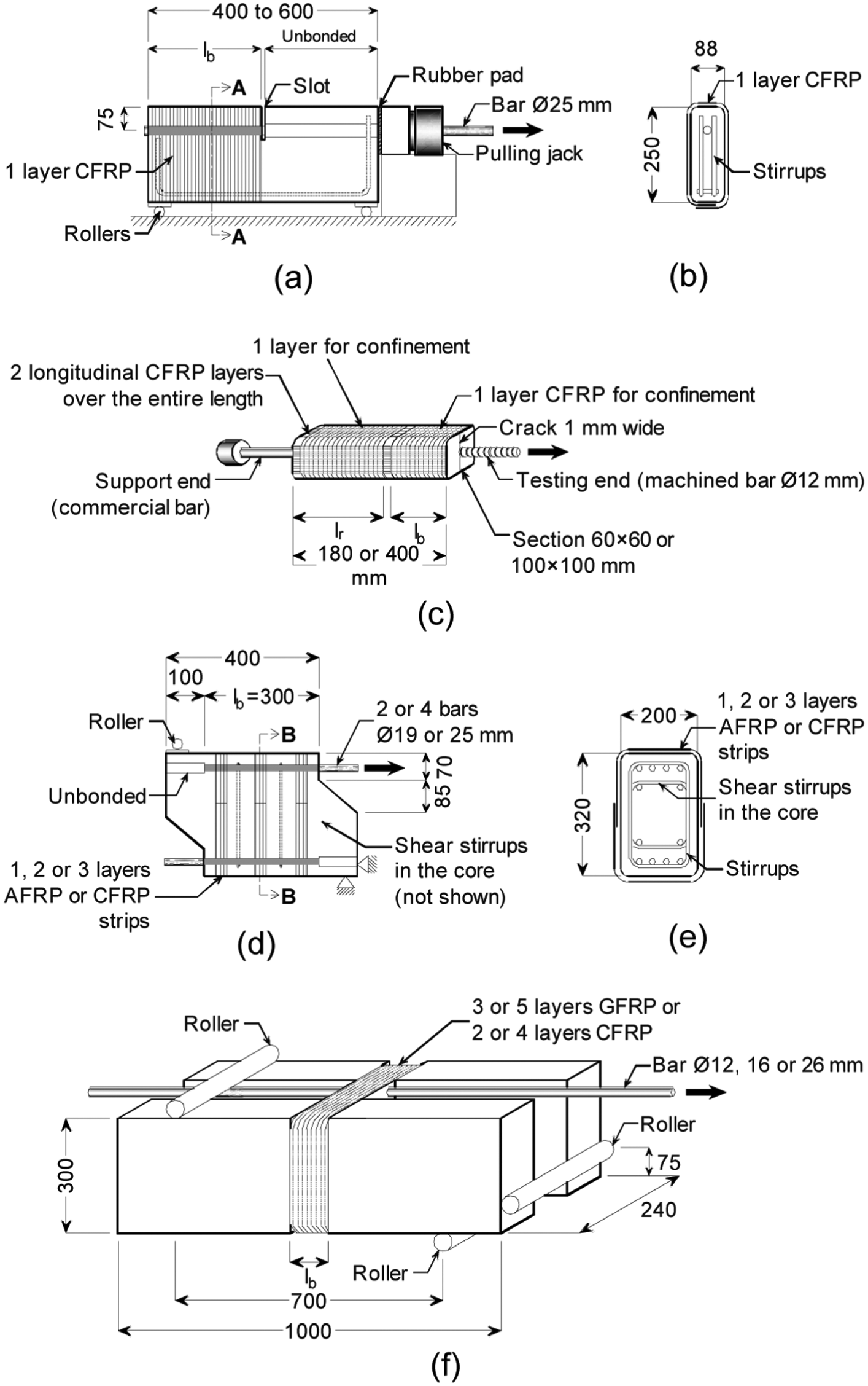
Specimens tested by Kono et al. (1997; (a) ‘Schmidt-Thrö’ pullout specimen and (b) section A-A), Tastani and Pantazopoulou (2010; (c) direct tension pullout specimen), Kono et al. (1999, 2000; (d) beam-end specimen and (e) section B-B) and Ozden and Akpinar (2007; (f) H-shaped beam-end specimen). Dimensions in millimetre.
More recently, Tastani and Pantazopoulou (2010) performed direct pullout tests using two bars anchored concentrically in a concrete prism (Figure 2(c)). Specially machined steel bars with two different nominal rib heights were anchored for short lengths (lb = 5db or 12db) at the testing end of the specimens, whereas a commercial bar with sufficient bonded length was anchored at the support end (shown as lr in Figure 2(c)). A total of two layers of CFRP fabric were bonded on each face of the specimens (parallel to the longitudinal axis) to transfer forces between the testing ends and to prevent failure of the concrete prism in tension. A confinement sheet was added around the support bar to improve its development capacity. For the specimens designed to evaluate the effect of confinement on bond strength, an additional FRP sheet was also wrapped around the test bar. Presplit specimens with a radial crack 1.0 mm wide were also tested (see testing end in Figure 2(c)). Average bond strengths increased by 130% and 44% in non-split and presplit specimens, respectively, but the bond strength results showed a large scatter. This was attributed to the highly variable properties of concrete in tension (Tastani and Pantazopoulou, 2010).
Beam-end specimens
Kono et al. (1999, 2000) conducted tests on small beam-end specimens with two or four bars anchored for a length lb = 300 mm as shown in Figure 2(d) and (e). One, two or three layers of aramid FRP (AFRP) or CFRP strips were wrapped along the anchorage length of the bars, whereas internal steel stirrups were also provided to confine the bars and the specimens’ core. The confinement enhanced the bond strength of the bars by a minimum of 18% and up to 44%. Despite the heavy internal reinforcement, the diagonal cracking observed across some of the specimens at failure suggests that shear (rather than splitting) dominated the behaviour. This can be possibly attributed to the small shear span ratio used in the tests (close to 1) and the resulting high shear forces.
In an attempt to eliminate shear and ‘active’ confinement effects due to loading at the supports, Ozden and Akpinar (2007) tested H-shaped beam-end specimens with an anchored bar confined with either glass FRP (GFRP) or CFRP sheets (see Figure 2(f)). Very short anchorage lengths of lb = 3.5db and 7db were selected to study local bond conditions. No internal steel stirrups were provided. The concrete cover was set constant and equal to 1db in all specimens. The bond strength of the anchored bars was enhanced by 16% and up to 42% when compared to unconfined specimens.
Beam specimens
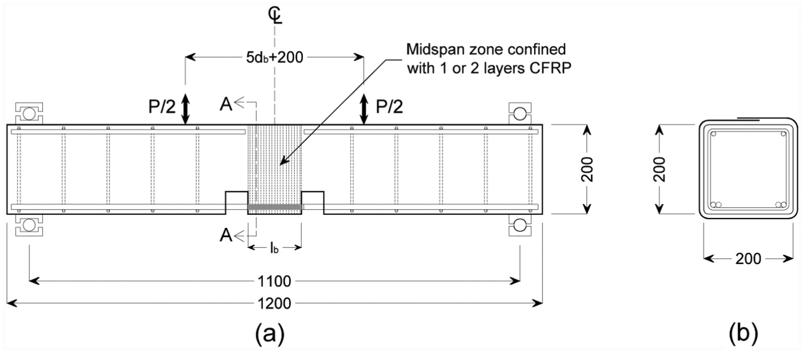
Kono et al. (1997, 1999) also tested large-scale beams in double curvature in an attempt to promote cover splitting within the midspan zone (see Figure 3). Different confining configurations were investigated including: (a) one layer of CFRP strips or continuous confinement (Kono et al., 1997) and (b) one or two layers of AFRP or CFRP strips (Kono et al., 1999). The beams failed at midspan due to a combination of shear and cover splitting. The shear strength of the beams was enhanced by approximately 80% with reference to unconfined counterparts. Although bond strength of the bars was enhanced by up to 115%, the different force mechanisms involved in the final failure make the interpretation of results difficult.
Beams tested in double curvature by Kono et al. (1999): (a) internal and external reinforcement and (b) section A-A. Dimensions in millimetre.
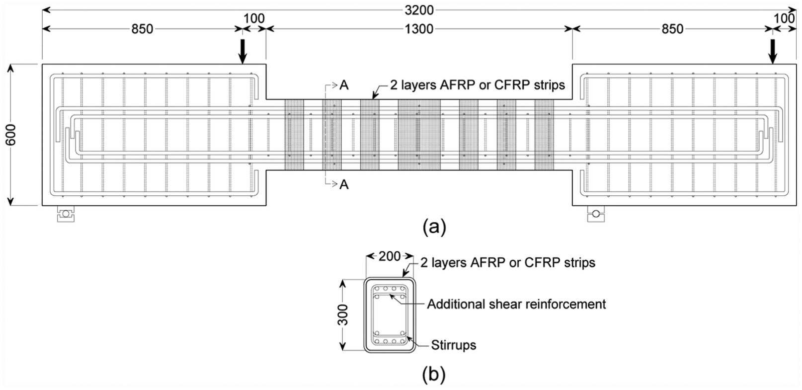
Hamad and Najjar (2002), Salwan (2003) and Hamad et al. (2004a, 2004b, 2004c) tested beam-splice specimens in four-point bending to examine the effect of FRP wraps on the bond strength of lap splices (see Figure 4). The specimens were designed to fail by splitting at midspan, where the main flexural reinforcement was lapped for a short length lb = 16db to prevent bar yielding. A total of one or two layers of GFRP or CFRP were bonded along the midspan zone using partial (1 or 2 strips) or continuous U-wraps. While the unconfined beams experienced sudden brittle failure due to severe splitting and spalling of the concrete cover around the lapped bars, the FRP-strengthened beams failed gradually. The FRP reinforcement also enhanced the bond strength of the splice by a minimum of 6% and up to 34% when compared to unconfined beams (Hamad and Rteil, 2006). Unlike Kono et al.’s specimens, beam-splice specimens are subjected to simple bending at the midspan, thus simplifying the comparison of results.
Beam-splice specimens tested by Hamad et al. (2004a, 2004b, 2004c) and Hamad and Rteil (2006): (a) internal and external reinforcement and (b) section A-A. Dimensions in millimetre.
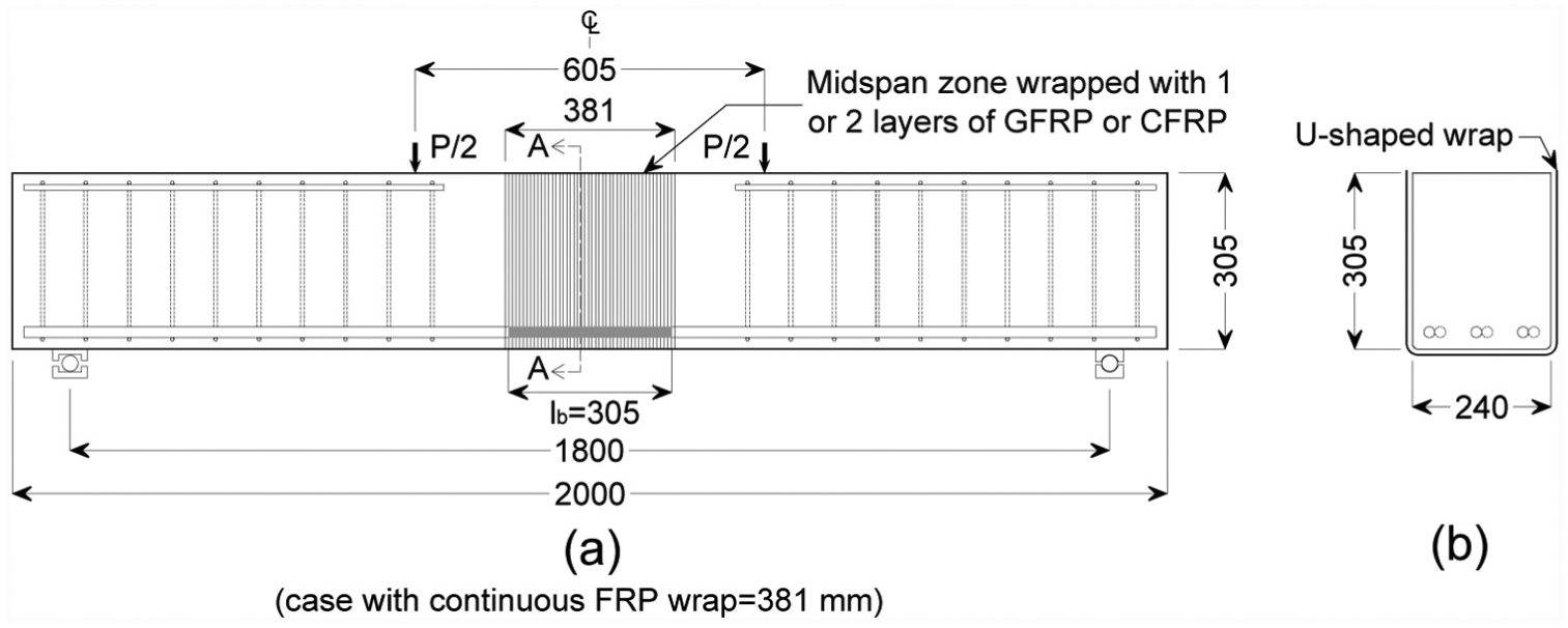
Harajli (2006) tested beam-splice specimens to investigate the local bond–bar slip relationship of very short lap splices with lb = 5db (see Figure 5). The beams were subjected to four-point bending using static and cyclic loading. Two notches at the bottom of the beams defined the lap length and exposed the main flexural bars for slip measurements. As expected, failure of the unconfined specimens was controlled by splitting. The use of one or two layers of CFRP at the lap zone was effective at delaying failure and enhancing the bond strength of the lapped bars by up to 70% with reference to the unconfined counterparts.
Beam-splice specimens tested by Harajli (2006): (a) internal and external reinforcement and (b) section A-A. Dimensions in millimetre.
Rteil et al. (2007) performed four-point bending tests (as shown in Figure 6) on beam anchorage specimens under static and fatigue loading. A bond splitting failure was promoted at the beam ends by anchoring the bottom bars for a short length of approximately lb ≈ 13db. The rest of the bar length was unbonded from the concrete using polyethylene pipes. Two notches at the bottom of the beams defined the lap length at the beam ends and exposed the main flexural bars for measurements. The anchored bar zone was strengthened with one layer of U-shaped CFRP fabric. The bond strength of the CFRP-confined beams subjected to static load was enhanced by 38% with reference to the unconfined counterparts. Similarly, the bond strength of CFRP-confined beams subjected to fatigue load increased by 41% at 1000 cycles and by 22% at 100,000 cycles compared to unconfined specimens. While bar slip increased with the number of applied cycles, the slip in the unconfined beams increased exponentially during the last 10% of the beams’ life, whereas the slip increased constantly up to failure in CFRP-confined beams. Similar beam anchorage specimens were tested by Hage Ali (2003), but in this case, the bond strength was enhanced by 6% and up to 9% only. Due to the test set-up, bond strength results obtained from these beams may be influenced by additional confining stresses generated by the reaction forces at the supports. It is unclear whether this effect was considered in the reported results.
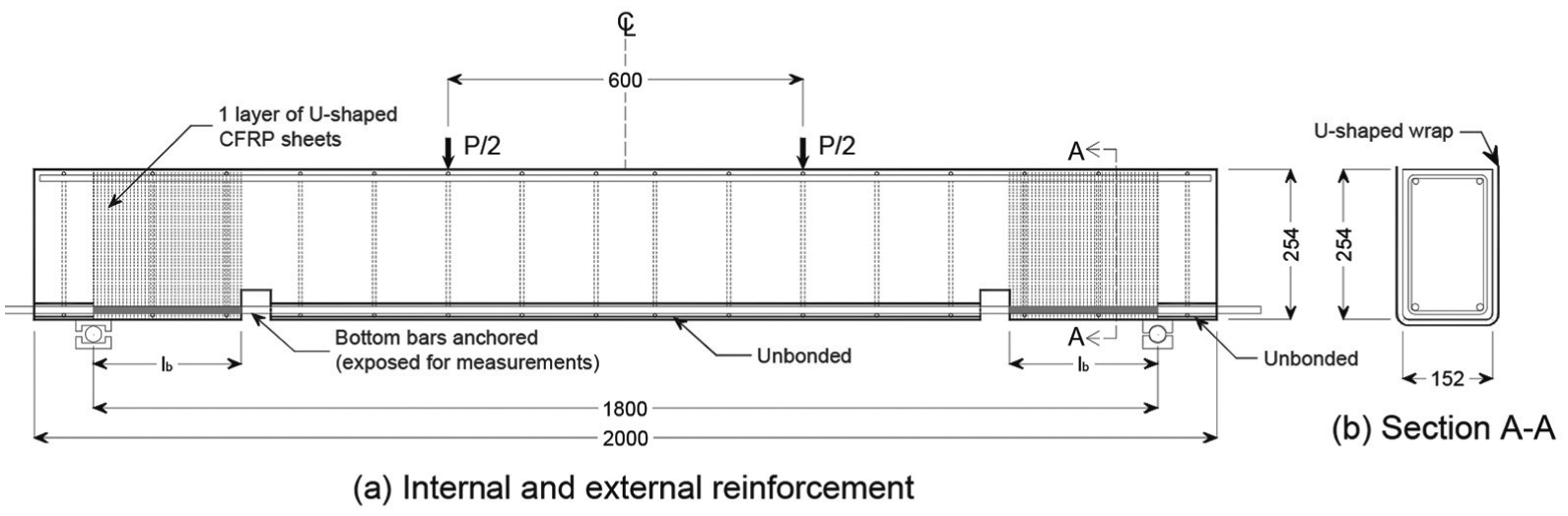
Beam anchorage specimens tested by Rteil et al. (2007): (a) internal and external reinforcement and (b) section A-A. Dimensions in millimetre.
More recently, Garcia et al. (2014, 2015) investigated the bond strength enhancement resulting from the confinement provided by CFRP sheets in 24 beam-splice specimens tested in flexure, similar to those tested by Harajli (2006) and Hamad et al. (2004a, 2004b, 2004c). Lap lengths of 10db and 25db were used to examine the mobilised ‘local’ and average bond strengths, respectively. A total of one or two layers of continuous CFRP fabric confined full lap length. The experimental results showed that the CFRP strengthening enhanced the bond strength of the lapped bars by up to 65% with reference to unconfined beams, thus improving significantly the overall behaviour of the beam-splice specimens. The results also corroborated research findings by Kono et al. (1997) as the bond strength enhancement was relatively independent of the lap length.
Discussion of parameters influencing the effectiveness of FRP confinement
The literature survey indicates that extensive research on the subject has been performed until now. The different approaches adopted to investigate the bond behaviour of lap-spliced elements strengthened with FRP also reflect the numerous parameters influencing bond behaviour and the effectiveness of FRP confinement, as discussed in the following.
Type of specimen and lap splice length
The lap length used to investigate the effect of FRP confinement on lap-spliced members is generally selected on the basis of the adopted experimental approach and on the level of stress expected to be developed in the bars. When test specimens are designed according to a capacity–ductility approach, FRP confinement has a minor influence if laps are relatively short and bar pullout dominates failure. Conversely, the influence of confinement is important when concrete splitting dominates failure. For instance, in columns with relatively long splices (lb > 35–40db), the confinement provided by the concrete cover and internal stirrups may be sufficient to develop yielding in the bars, resulting in rather stable and ductile hysteresis loops. Consequently, the behaviour of these columns is only slightly improved by additional FRP confinement at the lapped zone (Bournas and Triantafillou, 2011; Bousias et al., 2007; ElGawady et al., 2010). The improvement is particularly evident at higher ductility levels of response when the FRP confinement prevents premature spalling of the concrete cover and delays possible buckling of the spliced bars (Pantazopoulou et al., 2016).
Although FRP confinement has proven very effective in improving the behaviour of lap-spliced columns, the majority of the tested specimens to date differ considerably in size and geometry, bar and concrete characteristics, type and layout of the FRP confinement and lap length. Due to this lack of uniformity, the results and conclusions drawn from an experimental programme may not be directly comparable to others. Additionally, the effect of FRP strengthening on the local bond behaviour is difficult to assess due to the practical difficulties in monitoring the strains along the lapped bars (unless closely spaced strain gauges are fixed on the bars).
In general, when a bond strength approach is adopted in the investigations, the selected bonded length depends on whether local or average bond strength is of interest. Bonded lengths of anchorages and lap splices are usually ‘short’ enough to prevent bar yielding so that the bond mechanism is not affected (i.e. lb < lb,min, where lb,min = minimum bonded length) but also sufficiently ‘long’ to allow the contribution of a considerable number of bar ribs to bond resistance. The test specimens described previously in section ‘Bond strength approach’ follow this rationale and adopted lap lengths in the range 5db ≤ lb ≤ 15db. The results of these specimens can be also useful, for instance, to adjust existing bond–slip relationships so as to account for the FRP strengthening.
Given the different factors affecting bond, an experimental methodology that combines the use of tests on standard specimens (e.g. beam-end or beam-splice specimens), along with tests on lap splice lengths typical of substandard RC columns (lb = 20–30db), can provide a valuable insight into the bond behaviour of FRP-confined members. It should be also noted that current bond provisions of modern design codes such as ACI Committee 318 (2011) and fib Model Code 2010 (2013) were developed using large databases of test results from beam-splice specimens. As a consequence, these beams can provide suitable data to develop bond strength models that can be included in future revisions of FRP guidelines.
Layout and thickness of FRP reinforcement
The use of different FRP reinforcement layouts and thickness or number of layers (nftf) was investigated by several researchers. The effectiveness of discontinuous FRP reinforcement (strips) has been studied in columns (Harajli and Rteil, 2004), beam-end and beam specimens (Kono et al., 1997, 1999, 2000) and beam-splice specimens (Hamad et al., 2004a, 2004b, 2004c). Compared to continuous strengthening applications, discontinuous reinforcement is less effective and, therefore, rarely used in practical wet lay-up applications. The strengthening of lap-spliced members usually involves the full wrapping of the cross section with FRP sheets. Nonetheless, U-shaped FRP sheets have been successfully used in beam specimens as shown in Figures 4(b) and 6(b). While U-wraps are less effective than full wraps, they are generally more practical for strengthening beams where the presence of a slab could prevent full wrapping. Such a confinement layout, however, is rarely required in columns, which are more vulnerable than beams. As a result, it is recommended that future tests focus on investigating continuous and either full or U-wrap strengthening applications.
Practical strengthening applications generally use a minimum of one continuous layer of fully wrapped FRP reinforcement. This minimum amount of FRP confinement may be sufficient to develop the full capacity of RC columns with typical lap splices of length lb = 20–30db (e.g. Breña and Schlick, 2007; ElSouri and Harajli, 2011; Garcia et al., 2014; Ghosh and Sheikh, 2007; Harajli and Dagher, 2008; Harajli and Khalil, 2008). Additional FRP layers can provide more confining pressure to the lap splice, enhancing its bond strength and improving further the specimen behaviour. However, similar to confinement by internal steel reinforcement, FRP confinement only enhances bond strength up to the point where bar pullout dominates failure. Few researchers have investigated experimentally the maximum achievable bond strength enhancement as a function of the amount of FRP confinement (Hamad et al., 2004b; Harajli et al., 2004). In addition, the effectiveness of FRP confinement is limited by yielding of the lapped bars as bond strength increases only marginally after this point (Harajli and Dagher, 2008). As no significant bond enhancement is expected in the post-yield stage, it seems uneconomical to provide more confinement than that necessary to develop yielding of the bars (unless it is required for other strengthening objectives). Indeed, previous research (Hamad et al., 2004a, 2004b, 2004c, Garcia et al., 2014) suggests that the use of two layers of FRP can be sufficient to mobilise the maximum achievable bond strength of typical lap splices.
Strains developed in the FRP
Due to their intrinsic mechanical characteristics, FRPs remain essentially elastic until failure. As a result, the confining stress (fl) applied by the FRP reinforcement on a lap-spliced member depends on the effective strain (εfe) developed in the main direction of the fibres. Despite this, not all experimental studies provide sufficient information on the evolution of FRP strains to allow evaluating the effective confining stress at bond failure. In the case of lap-spliced columns, studies often report ‘maximum’ FRP strains recorded at the last test stages, when significant concrete cover spalling, concrete crushing and/or bar buckling can affect the strain readings. Additionally, FRP strains are also affected by the location of the strain gauges along the member and across the cross section. For instance, large FRP strains are usually recorded close to the base of columns (Ma and Xiao, 1999; Schlick and Breña, 2004). While such large strains have been mainly attributed to the variation of flexural moment over the column height, they could also be a result of the development of other degradation mechanisms (e.g. bar bucking). Also, very high strain values can be recorded near the corner of rectangular sections where rupture of the FRP confinement is more likely to occur (Sause et al., 2004; Walkup, 1998).
In lap-spliced members, the effectiveness of the passive confining action from the FRP relies heavily on concrete dilation around the lapped bars, which in turn depends on bar slip (e.g. Tastani and Pantazopoulou, 2008, 2010). Test results from lap-spliced circular columns indicate that the ‘onset’ of bar slip occurs at dilation strains between 1000 and 2000 µε (Seible et al., 1995). Based on this observation, a limiting (effective) FRP strain of 1000 µε was suggested for the design of FRP strengthening solutions to ‘prevent’ slippage of the lapped bars. This value is in agreement with more recent test data indicating that FRP strains measured at peak capacity of rectangular and circular columns never exceed 8% and 15% of the ultimate elongation strain of carbon fibres (εfu = 15,000 µε), respectively (Harajli, 2009; Tastani and Pantazopoulou, 2006, 2010). These results indicate that debonding of lapped bars typically occurs at low lateral strain values, which could be still sufficient to develop the full capacity of the lapped bars as evidenced by the tests summarised in section ‘Capacity–ductility approach: tests on cantilever columns’.
FRP strains were found to increase with decreasing values of minimum clear concrete cover to bar diameter cmin/db (Harajli, 2008; Harajli and Dagher, 2008). This can be attributed to the fact that as the ratio cmin/db reduces, the formation of premature splitting cracks tends to mobilise the FRP confining action earlier. Tests results from lap-spliced columns indicate that the additional contribution of FRP confinement to the column capacity, with reference to the capacity of an unconfined specimen, is higher as the ratio cmin/db reduces (Harajli and Dagher, 2008). Although the thickness of the concrete cover is crucial in bond splitting failures, its importance is frequently overlooked, and actual measured covers from tested specimens are rarely reported, thus preventing accurate computations of bond strength.
Properties of FRP
The use of a constant effective strain in the design of strengthening solutions for lap-spliced members (see previous section) implies that stiff CFRP wraps could be expected to be more effective than AFRP or GFRP wraps because the former can mobilise higher confining pressures. However, very few studies have compared the effectiveness of different types of FRP confinement in improving the behaviour of lap-spliced columns (e.g. Breña and Schlick, 2007; Haroun et al., 1999; Thermou and Pantazopoulou, 2009). In these studies, lap-spliced columns confined with the same number of GFRP, AFRP or CFRP layers were capable of developing their full capacity. For similar values of axial stiffness nftfEf, the variation of the type of the FRP sheet does not affect the observed response (Thermou and Pantazopoulou, 2009).
The influence of the type of fibre on bond strength has also been studied using a bond strength approach but to a very limited extent. Kono et al. (1999, 2000) found that the use of CFRP strips (see Figure 2(d)) only increased marginally the bond strength of the bars when compared to AFRP strips. Hamad et al. (2004c) tested beam-splice specimens confined with either GFRP or CFRP sheets (Figure 4) and concluded that the type of fibre had no significant effect on the bond strength of the lapped bars. It should be noted, however, that similar confinement layouts and FRP axial stiffness were used. Ozden and Akpinar (2007; see Figure 2(f)) indicated that the bond strength enhancement due to FRP confinement depended on the type of fibre, but a detailed analysis of their results leads to conflicting conclusions: a comparison between specimens with similar FRP axial stiffness shows that bar bond strength is only 2%–6% higher in specimens wrapped with five GFRP layers than in those wrapped with two CFRP layers. The marginal bond enhancement difference between wrapping with five and two layers may be due to a lower effectiveness of the outer FRP layers in applying confinement compared to the inner layers and also to possible slippage between such layers. In view of these inconsistencies, the effect of the type of FRP on anchorages and lap splices failing in bond splitting should be further investigated.
Concrete and bar properties
Both the material properties of concrete and the geometry of the reinforcing bars play a major role in defining the bond–slip behaviour at the steel–concrete interface. While the compressive (fc) and tensile (fct) strength of concrete affect pullout and splitting bond strength, respectively, rib geometry and relative rib area of the bars are critical in ensuring the adequate transfer of bond forces through a rib bearing mechanism and are known to influence the extent of bar slippage fib Bulletin 10 (2000).
In order to assess the effect of concrete compressive strength on the additional bond strength provided by FRP wraps, the experimental programme conducted by Hamad et al. (2004b) comprised normal and high-strength RC beam-splice specimens (see section ‘Beam specimens’ and Figure 4). Nominal concrete compressive strengths of fc = 27.6 and 69.0 MPa were examined. As expected, the lapped bars used in high-strength beams mobilised a higher bond strength than that of normal-strength beams. Nonetheless, for equivalent test parameters and FRP layout, both groups of beams exhibited similar failure modes and bond strength enhancement values, thus suggesting that fc has a relatively minor influence on such enhancement.
Ozden and Akpinar (2007) studied the influence of different concrete strengths and bar diameters on the bond strength of anchorages using the specimens shown in Figure 2(f). Nominal concrete compressive strengths of fc = 20 and 40 MPa were examined. The average bond strength enhancements after FRP wrapping were similar and ranged from 16% to 42% for concrete of 20 MPa, and from 18% to 40% for concrete of 40 MPa. The bond strength enhancement increased slightly with an increase in the bar diameter. For concrete of 20 MPa, average bond strength enhancements were 28%, 31% and 35% for db = 12, 16 and 26 mm, respectively. For the same bars anchored in concrete of 40 MPa, similar enhancements of 26%, 32% and 37% were obtained. The higher bond strength enhancement observed for the 16- and 26-mm bars (over the 12-mm bars) can be partially attributed to the larger contribution of FRP confinement on larger size bars, an effect which is also observed in lap splices confined with transverse steel stirrups (ACI Committee 408, 2012). However, the large scatter observed in the bond strength results and the use of a constant cmin/db ratio of 1.0 in the experimental study suggest that additional test data would be beneficial to assess the effect of bar diameter.
Tastani and Pantazopoulou (2010) also examined the influence of concrete properties on the bond strength of specially machined bars. Two different types of concrete were examined: (a) concrete with tensile strength fct = 2.05 MPa and apparent porosity of 4.33% and (b) concrete with fct = 2.30 MPa and apparent porosity of 8.16%. The test results did not confirm any effect of these variables on the bond strength of the bars. As the machined bars had nominal rib heights of 0.5 and 1.1 mm and a rib face angle of 90°, the authors also investigated the effect of rib height on bond behaviour. Tastani and Pantazopoulou (2010) reported that, as expected, bars with higher ribs mobilised higher bond strengths due to enhanced rib bearing action but led to smaller bar slip thus resulting in less ductile failures. Although insightful, these results relate to rib bar geometries that are not typical of commercial reinforcement, generally characterised by rib face angles ranging from 30° to 50°. Moreover, it is more convenient to compare the relative improvement that the FRP provides to confined specimens over unconfined specimens in terms of bond strength and ductility for different rib areas, rather than comparing the absolute bond improvement. It has been also argued that FRP-strengthened lap-spliced elements have highly variable properties of concrete in tension, but tests performed by the authors (Garcia et al., 2014, 2015) and by other researchers (Hamad et al., 2004a, 2004b, 2004c) on beam-splice specimens indicate that the FRP strengthening reduced the concrete variability in tension, thus providing more consistent bond strengths. In summary, the influence of concrete strength and bar characteristics requires further investigation.
Cross-sectional geometry and aspect ratio
The concrete core of a FRP-confined circular column subjected to pure axial compression is effectively confined as the confining action is uniform over the cross section. Conversely, it is generally accepted that some regions of a rectangular cross section remain ‘unconfined’ due to parabolic arching action (see Figure 7). Hence, reinforcing bars located in the shaded regions of Figure 7 are conservatively considered as unconfined, whereas those located at the corners are assumed as fully engaged. Several experimental studies have confirmed the lower effectiveness of FRP confinement in improving the response of lap-spliced columns with rectangular sections (Ghosh and Sheikh, 2007; Haroun and Elsanadedy, 2005; Haroun et al., 1999, 2003; Saatcioglu and Elnabelsy, 2001). In an attempt to bypass this drawback, the shape of the cross sections (before applying the FRP) has been modified using oval concrete bolsters (Priestley et al., 1992; Priestley and Seible, 1995), fast-curing cement (Saadatmanesh et al., 1997b) or epoxy grout (ElGawady et al., 2010) to form elliptical cross sections. Precast mortar blocks (Haroun et al., 2003; Haroun and Elsanadedy, 2005) or steel plates (Chang et al., 2000) were also used to form semi-rounded cross sections. With the exception of the tests by Chang et al. (2000), studies showed that the overall behaviour of the oval-shaped columns was only slightly better than that of rectangular columns, and thus such shape modifications seem of little benefit.
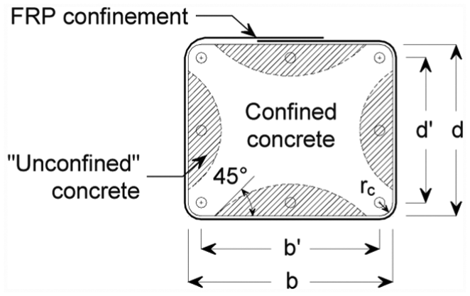
Cross section effectively confined in rectangular columns under pure axial compression (adapted from fib Bulletin 14 (2001)).
Although the arching action shown in Figure 7 can develop in rectangular sections under pure axial compression (Mirmiran et al., 1998; Rochette and Labossière, 2000), it may not develop in the same way during bond splitting failures when part of the concrete and the lapped bars are subjected to tension. Under this condition, FRP wraps are mainly expected to control the widening of splitting cracks forming on the tensioned side of the section. Indeed, it is the ability of the FRP reinforcement to control the development of splitting cracks that determines the effectiveness of the FRP strengthening by increasing the bond strength of ‘unconfined’ bars, as confirmed experimentally by Ozden and Akpinar (2007), see Figure 2(f).
In an attempt to assess the effectiveness of CFRP reinforcement on the seismic performance of members with different cross section shapes, Harajli (2009) compared test results from rectangular (Harajli and Dagher, 2008; Harajli and Rteil, 2004) and circular (Harajli and Khalil, 2008) lap-spliced columns. Harajli concluded that the section shape had no significant effect on column performance when CFRP was used for lap splice strengthening. However, a direct comparison of performance between the rectangular and circular columns discussed in Harajli (2009) is difficult because the confinement effectiveness is different in such elements (only corner bars in square sections are effectively confined), as well as due to the different test conditions and geometry in elevation. More refined standardised methodologies should be developed to enable comparisons of tests performed on specimens with different geometries.
In a column subjected to axial compression, the effectiveness of FRP confinement reduces as the aspect ratio of the cross section increases (aspect ratio = long column side/short column side). As a consequence, current FRP guidelines suggest ignoring the effect of confinement in rectangular columns with aspect ratios >2 or face dimensions exceeding 900 mm (e.g. ACI Committee 440, 2008; CNR, 2012). It has been shown that CFRP-confined columns with lap splices in the range of lb = 30–35db and cross section aspect ratio of 2 can perform satisfactorily (ElGawady et al., 2010; ElSouri and Harajli, 2011; Harajli and Dagher, 2008; Harajli and Rteil, 2004). Moreover, the use of one CFRP wrap was very effective in improving the behaviour of lap-spliced (lb = 30db) shear walls with cross section of 150 × 1200, that is, an aspect ratio of 8 (Layssi et al., 2012). These results suggest that the aspect ratio limitation imposed by current FRP guidelines (that essentially assumes that FRP only confines the section corners) may be conservative for lap splice strengthening, and thus, such limitation should be revised.
Damage level before FRP strengthening
Only a few studies have investigated the use of FRP as a strengthening solution in lap-spliced damaged specimens. Saadatmanesh et al. (1997a) examined the effectiveness of concrete rehabilitation and FRP strengthening on circular and square columns that were damaged in a previous experimental study (Saadatmanesh et al., 1996). The rehabilitation included the removal and replacement of damaged concrete with new quick-setting concrete. After the rehabilitation, an oversized precured GFRP shell was wrapped around the column leaving a small gap between the shell and the concrete surface. The gap was filled with pressure-injected epoxy to provide active confinement. The rehabilitation and strengthening enhanced the capacity of the columns by up to 38% with reference to the original ‘as-built’ specimens. In general, the rehabilitated and strengthened columns had lower flexural stiffness due to bond deterioration and damage accumulated during the initial tests.
Ilki et al. (2004) tested a damaged lap-spliced rectangular column with plain (smooth) bars rehabilitated and strengthened with six layers of CFRP. In this case, the low-strength damaged concrete (fc = 13.4 MPa) was replaced using high-strength epoxy mortar with a compressive strength of 50 MPa. The rehabilitation and subsequent strengthening enhanced the capacity of the column by 34% in comparison to its original capacity. Moreover, both capacity and ductility were improved considerably with reference to those of an identical undamaged specimen. Ilki et al. (2004) also concluded that the level of pre-damage had no significant adverse effect on the performance of the rehabilitated and strengthened specimen, but they also suggest performing more tests to draw more general conclusions. However, the individual contribution of the rehabilitation solution and that of the CFRP strengthening is unclear.
Thermou and Pantazopoulou (2009) tested previously damaged square columns (Syntzirma and Pantazopoulou, 2006) after strengthening. In this testing programme, the damaged concrete at the splice zone was not rehabilitated, and GFRP and CFRP wraps with similar axial stiffness were used. The adopted strengthening solutions enhanced the capacity of the columns by a minimum of 2% and up to 55% in comparison to the original specimens. The limited enhancement in capacity was attributed to bar yielding promoted by the use of closely spaced internal steel stirrups (spacing = 70 mm) and the relatively long lap length used in some of the columns (lb = 36db).
The results from the aforementioned studies indicate that the effectiveness of an FRP strengthening solution depends heavily on the extent and quality of rehabilitation of the concrete around the lap splice zone. Overall, the influence of the initial level of damage is difficult to assess not only due to the limited number of test results available in the literature, but also due to the different strengthening objectives between experimental programmes. As a consequence, the conclusions of these studies may not be easily generalised.
Other parameters
Other parameters not thoroughly investigated (thus conclusions are difficult to draw) but available in the literature are as follows:
Type of load and load path. These include the influence of dynamic load on lap splices using shake table tests, partially spliced columns (50%) subjected to pseudo-dynamic (PsD) tests (Chung et al., 2008), quasi-static cyclic tests on repaired and FRP-strengthened lap-spliced square columns using a near-field earthquakes (Thermou and Pantazopoulou, 2009) and cyclic fatigue load (Alyousef et al., 2015, 2016).
Use of lap splices with plain (smooth) bars. The activation of the passive confining action from FRP wraps relies on concrete dilation produced by the bar ribs reacting against the surrounding concrete. Consequently, FRPs are less effective in enhancing the performance of RC columns with lap-spliced plain bars (Bousias et al., 2004; Bousias et al., 2007; Ilki et al., 2004; Yalçin and Kaya, 2004).
Corrosion of reinforcing bars. Significant corrosion can deteriorate the bond strength between bars and concrete. However, provided the failure is dominated by cover splitting, the bond behaviour of corroded anchorages and lap splices can still be effectively enhanced through externally bonded FRP reinforcement around columns (Aquino and Hawkins, 2007), as well as eccentric pullout specimens with L-shaped CFRP wraps (Soudki and Sherwood, 2003), concentric pullout specimens confined with CFRP sheets (Papakonstantinou et al., 2011; similar to those shown in Figure 2(c) and (d)), damaged beam-end specimens with or without low-strength mortar rehabilitation and strengthened with U-shaped CFRP wraps (Tastani and Pantazopoulou, 2007), beam anchorage specimens (Craig and Soudki, 2005) wrapped with U-shaped CFRP sheets, and beam-splice specimens wrapped with U-shaped CFRP sheets (Shihata and Soudki, 2012).
Predictive models and design guidelines
Table 1 summarises the predictive models available in the literature for FRP strengthening of RC members with substandard splices. The models are classified as (a) design models and (b) bond strength enhancement models, and their main features and limitations are discussed.
Predictive models for FRP strengthening of RC members with substandard anchorages and lap splices (units: MPa, mm and N).
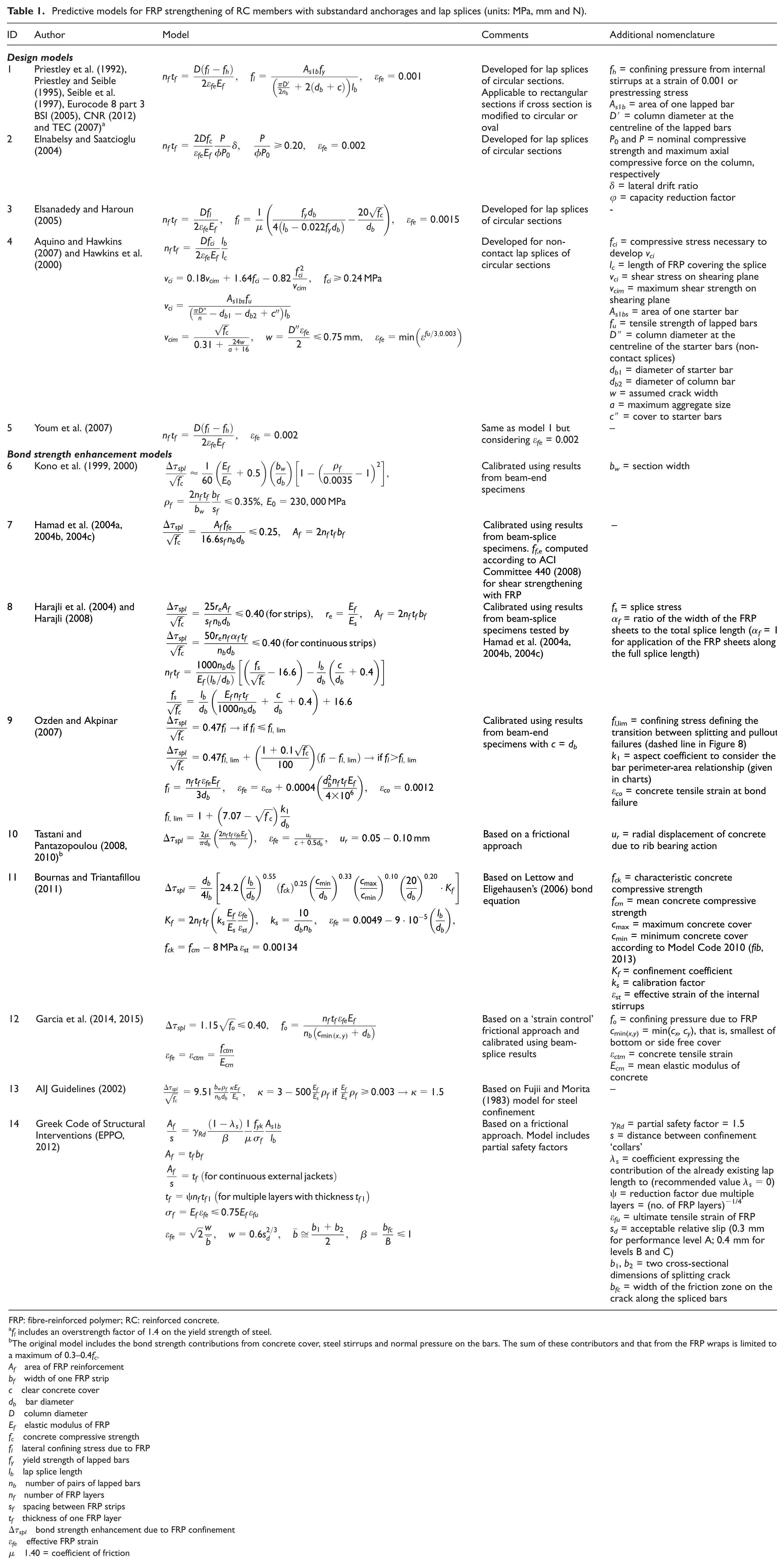
FRP: fibre-reinforced polymer; RC: reinforced concrete.
fl includes an overstrength factor of 1.4 on the yield strength of steel.
The original model includes the bond strength contributions from concrete cover, steel stirrups and normal pressure on the bars. The sum of these contributors and that from the FRP wraps is limited to a maximum of 0.3–0.4fc.
Af area of FRP reinforcement
bf width of one FRP strip
c clear concrete cover
db bar diameter
D column diameter
Ef elastic modulus of FRP
fc concrete compressive strength
fl lateral confining stress due to FRP
fy yield strength of lapped bars
lb lap splice length
nb number of pairs of lapped bars
nf number of FRP layers
sf spacing between FRP strips
tf thickness of one FRP layer
Δτspl bond strength enhancement due to FRP confinement
εfe effective FRP strain
µ 1.40 = coefficient of friction
Design-oriented models
In these models, the FRP thickness required to strengthen the lapped zone is computed directly using equations derived from test results on circular and rectangular column specimens.
Priestley et al. (1992), Priestley and Seible (1995) and Seible et al. (1997) proposed the first model for FRP strengthening of columns with substandard lapped bars (see model 1 in Table 1). The confining stress (fl) required to develop the tensile strength of the bar is computed using a frictional resistant approach that assumes a constant shear stress along potential splitting planes forming around a lapped bar. Lap splice failure is prevented by limiting the FRP strains to an effective strain εfe = 1000 µε, a value associated with the onset of ‘significant’ slip of lapped bars (Chai et al., 1991; Priestley et al., 1994). Although studies indicate that this model may lead to the use of very conservative amounts of FRP confinement (Harajli, 2008; Harajli and Khalil, 2008; Harries et al., 2006), it is still included in current guidelines for FRP strengthening (e.g. BSI, 2005; CNR, 2012). Using experimental strain readings from tests on GFRP-strengthened lap-spliced circular columns, Youm et al. (2007) suggested reducing the conservativeness of model 1 by adopting a higher value of effective FRP strain, εfe = 2000 µε (see model 5 in Table 1), but this has not been adopted in existing guidelines.
On the basis of a drift-based design approach for confinement of columns with steel stirrups (Saatcioglu and Razvi, 2002), Elnabelsy and Saatcioglu (2004) proposed model 2 to compute the thickness of FRP required to develop a predetermined drift demand (δ) in lap-spliced columns. In this model, the effective FRP strain is limited to εfe = 2000 µε. The applicability of the model is limited to columns under significant levels of axial load (see model 2 in Table 1).
Using Xiao and Ma (1997) bond–slip model for lap splices, Elsanadedy and Haroun (2005) proposed model 3 to calculate the thickness of the FRP required to develop yielding of substandard lapped bars in circular columns. The main feature of this model is that the minimum lateral confining stress fl provided by the FRP takes into account the bond strength contribution provided by the column concrete cover. However, the equation used to compute this contribution (taken from ACI Committee 408, 2005) may overestimate the bond strength of small diameter bars, resulting in low or even negative fl values for typical lap splice lengths of substandard structures. In addition, the model also implies that the applied strengthening will lead to yielding of the bars, which may not occur if the bars pullout.
Aquino and Hawkins (2007) and Hawkins et al. (2000) suggested using model 4 to compute the thickness of FRP required to strengthen columns with non-contact lap splices. The model assumes that a shearing plane with given crack width develops between the starter bars and the longitudinal column bars. Accordingly, sufficient shear stress (vci) should act over the failure surface to develop the full tensile strength of the starter bars before a bond failure occurs. The confining stress provided by the FRP should be equal to the normal compressive stress (fci) that enables the development of the stress vci, computed according to the model by Vecchio and Collins (1986). Hawkins and co-workers indicated that the use of their model would result in more economical design solutions than those given by the FHWA (2006) retrofitting guidelines.
As all predictive models previously discussed were developed for circular and rectangular columns with specific geometries, they may not be easily generalised to account for other cross-sectional geometries. Models adopting a general bond approach independent of the cross-sectional geometry, however, are available in the literature and are discussed below.
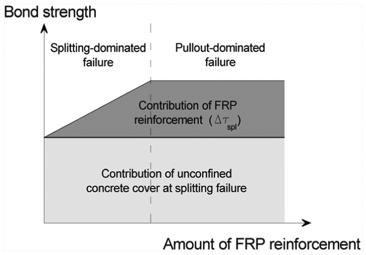
Bond strength models
The models described in the following compute the total bond strength of the anchorages and lapped bars as the sum of the contributions from concrete cover, and the bond strength enhancement provided by the FRP reinforcement (Δτspl in Figure 8).
Bond strength enhancement provided by FRP reinforcement in an existing lap-spliced member.
Based on test results from the beam-end specimens shown in Figure 2(c) and (d), Kono et al. (1999, 2000) modified a bond equation originally developed for internal steel confinement (Fujii and Morita, 1983) and proposed computing Δτspl using model 6 in Table 1. In this model, the effect of the strengthening on bond strength is independent of the FRP strains. The non-linear equation proposed by the authors follows the trend of the experimental results and suggests that the effectiveness of the external confinement reduces for FRP reinforcement ratios ρf >0.15%. The applicability of the model is limited to the maximum FRP reinforcement ratio examined in the experiments, ρf = 0.35%.
Hamad et al. (2004a, 2004b, 2004c) proposed model 7 based on calibration with limited test results from RC beam-splice specimens (Figure 4). The model is equivalent to that suggested by Orangun et al. (1975, 1977) to compute the additional bond strength provided by steel stirrups on lapped bars in RC beams. The influence of the FRP wraps on the bond strength of lapped bars is accounted for through an effective stress (ffe) calculated according to the ACI Committee 440 (2008) guidelines for shear strengthening. According to model 7, the bond strength enhancement due to the FRP reinforcement increases linearly with increasing amounts of FRP. Δτspl is limited to 0.25√fc to reflect the fact that the use of additional FRP wraps cannot lead to further enhancement of the bond strength as failure is dominated by pullout (see dashed line in Figure 8). The same limiting value was proposed by Orangun et al. for internal steel stirrups.
Using the experimental results of the beams tested by Hamad et al. (2004a, 2004b, 2004c, 2006), Harajli et al. (2004) proposed computing Δτspl using an equivalent area of FRP reinforcement to account for the different elastic moduli of steel stirrups and FRP (model 8 in Table 1). As FRP confinement controlled the widening of splitting cracks more effectively than internal steel stirrups, Harajli et al. limited Δτspl to 0.40√fc (Harajli, 2007; Harajli et al., 2004).
Ozden and Akpinar (2007) developed model 9 on the basis of the thick-walled cylinder analogy proposed by Tepfers (1973). Accordingly, the FRP wraps are assumed to exert a lateral confining stress fl over a thick-walled cylinder of diameter 3db. To compute fl, the model adopts an effective FRP strain that depends on the concrete surface strain at bond failure (εco), bar diameter and FRP axial stiffness. Model 9 was calibrated using test results from beam-end specimens (see Figure 2(f)) and was only validated for bars with very short anchorage lengths and with a clear concrete cover equal to the bar diameter (c = db).
Model 10 was developed by Tastani and Pantazopoulou (2008, 2010) adopting the ACI Committee 318 (2011) frictional model for bond and a thick-walled cylinder analogy. The model assumes the use of an effective FRP strain, which is determined as a function of the clear concrete cover, bar diameter and radial displacement produced by concrete dilation due to rib bearing action. The radial displacement is considered as half the bar slip based on tests on splitting-prone pullout specimens with a short bonded length lb = 8.33db (Lura et al., 2002). An important improvement in this model is the recognition of the strong interaction between bar slippage and FRP strains. However, to date, such interaction has not been examined extensively on large-scale lap-spliced members (Harajli and Dagher, 2008).
Based on the modifications of the bond strength equations for internal steel confinement (Lettow and Eligehausen, 2006; Zuo and Darwin, 2000), Bournas and Triantafillou (2011) proposed two models to calculate Δτspl. In these models, the effective strain developed in the FRP confinement (thus the associated Δτspl) reduce with the increase in the lap length-to-bar diameter ratio (lb/db) and is taken as 0 for ‘long’ lap lengths lb > 55db. As no studies appear to have examined in detail the development of FRP strains for different ratios lb/db, further experimental data are deemed necessary to validate this assumption. Model 11 in Table 1 was found to predict more accurately FRP strain readings from other tests on columns (ElGawady et al., 2010; Harajli and Dagher, 2008).
More recently, Garcia et al. (2014, 2015) proposed a practical strain control approach (model 12 in Table 1) to calculate the bond strength enhancement due to FRP confinement. The effect of the CFRP confinement is considered through an additional confining pressure fo assumed to act over a split cross-sectional area equal to (cmin(x,y)+db)·lb, as shown in Figure 9. The model was calibrated using experimental data from normal-strength FRP-strengthened beams with different lap splice lengths tested by the authors (as described in section ‘Beam specimens’), and by Hamad et al. (2006). Figure 10 compares the predictions of model 12 with the experimental results from the above beam tests. Despite the different test parameters and lap length examined in these different experimental programmes, it is evident that the proposed equation matches consistently the trend of results. Moreover, previous research (Garcia et al., 2014, 2015) has shown that, compared to existing strain control models (Bournas and Triantafillou, 2011; Hamad et al., 2004a, 2004b, 2004c, 2006; Harajli et al., 2004), model 12 predicts more consistently the bond strength enhancement due to FRP confinement, as well as the actual FRP strains mobilised at bond failure.
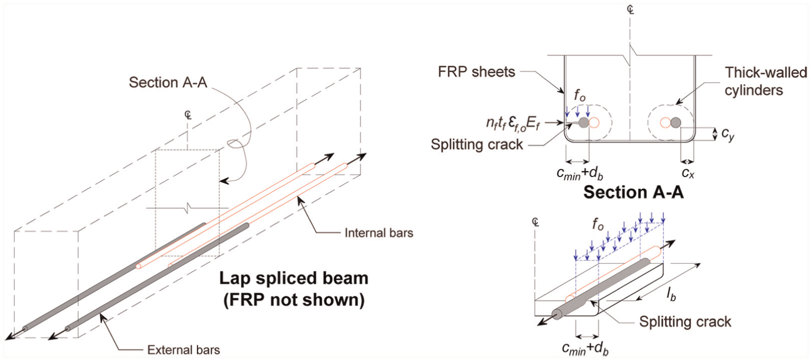
Bond splitting failure assumptions in CFRP-confined splices assumed to develop model 12.
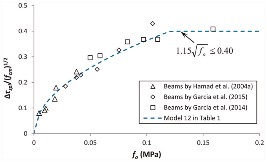
Comparison of proposed equation with experimental results, FRP-confined beam-splice specimens.
The accuracy of model 12 in predicting the bond strength enhancement of lapped or anchored steel bars is further assessed using an extended test data set collected from the existing literature. The following criteria were used to select the data:
The tests were carried out on beam-splice or pullout specimens with lap or anchorage lengths in the range of lb = 5–25db.
The lapped or anchored bar remained elastic during the tests.
The experimental maximum bar stress (or bond strength) mobilised in the lapped or anchored bars was explicitly reported, and this value could be assumed as uniform over the lap or anchorage.
The FRP properties were either reported, or these could be found in the manufacturers’ technical data sheets.
Minimum clear concrete cover was reported and complies with the applicability limits of the proposed model 12, that is, approximately 0.8 ≤ cmin/db ≤ 2.0.
The above criteria led to a data set of 35 beam-splice specimens and 92 pullout specimens, which are summarised in Tables 2 and 3, respectively. In these tables, τspl, t is the bond strength mobilised in the test, Δτspl, t is the bond strength enhancement due to the FRP confinement only and the rest of the variables are as defined in Table 1. The value Δτspl, t was calculated as the difference between the bond strength of FRP-confined specimens and that of corresponding unconfined control specimens. These tables also compare the experimental normalised bond strength enhancement (Δτspl, t /fcm1/2) with the analytical predictions calculated with model 12 (Δτspl/fcm1/2). For the beam-splice specimens (Table 2), model 12 predicts the results with a mean test/prediction ratio (T/P) of 1.13 and a standard deviation (SD) of 0.43. For the pullout specimens included in Table 3, such values are T/P = 1.36 and SD = 0.80. While the model predicts conservatively the experimental results, it also yields a relatively larger scatter, which was somehow expected given the large variability of concrete in tension, as well as the different test programmes considered in the assessment.
Test results and analytical predictions of bond strength and bond strength enhancement for beam specimens.
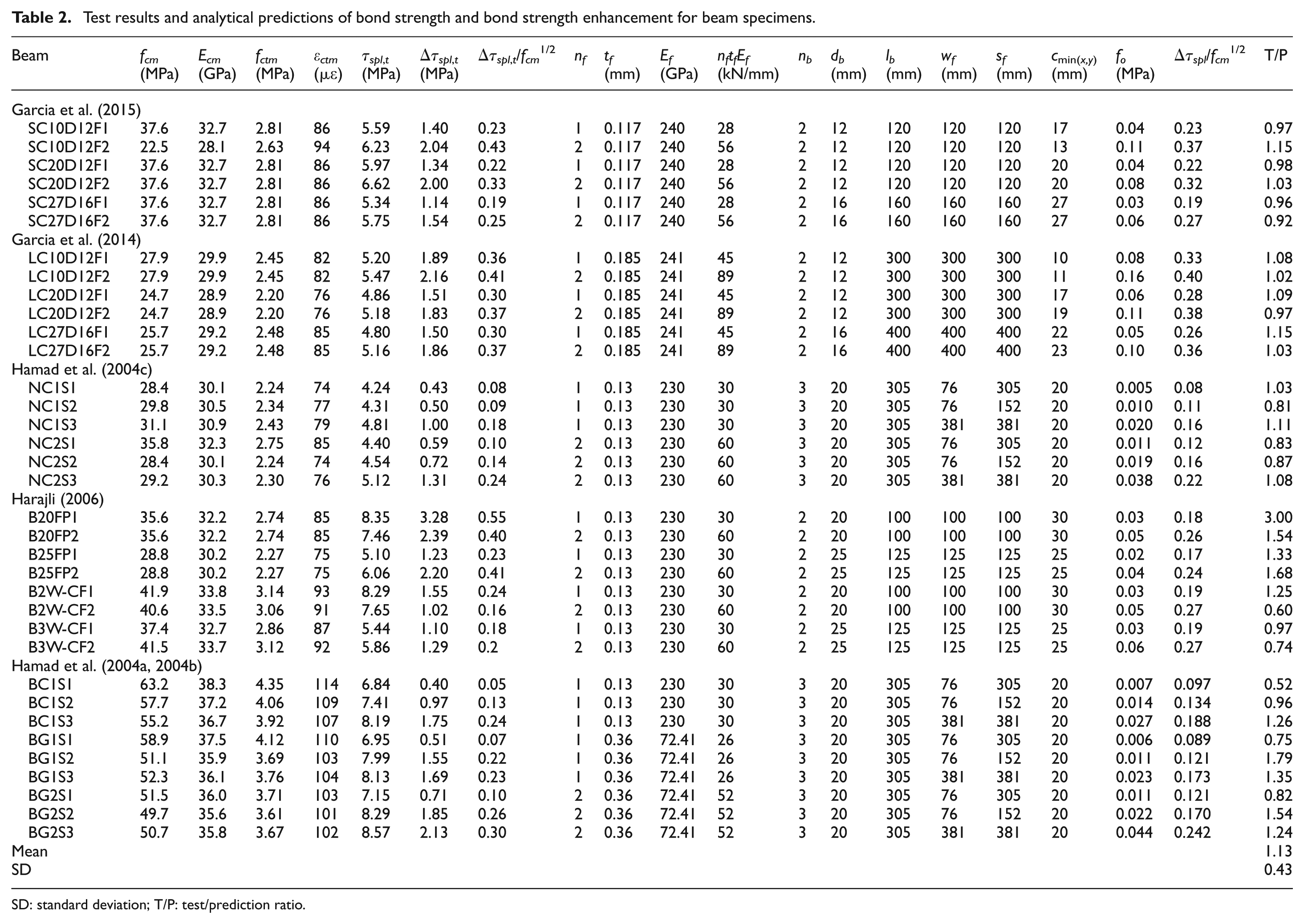
SD: standard deviation; T/P: test/prediction ratio.
Test results and analytical predictions of bond strength and bond strength enhancement for pullout specimens.
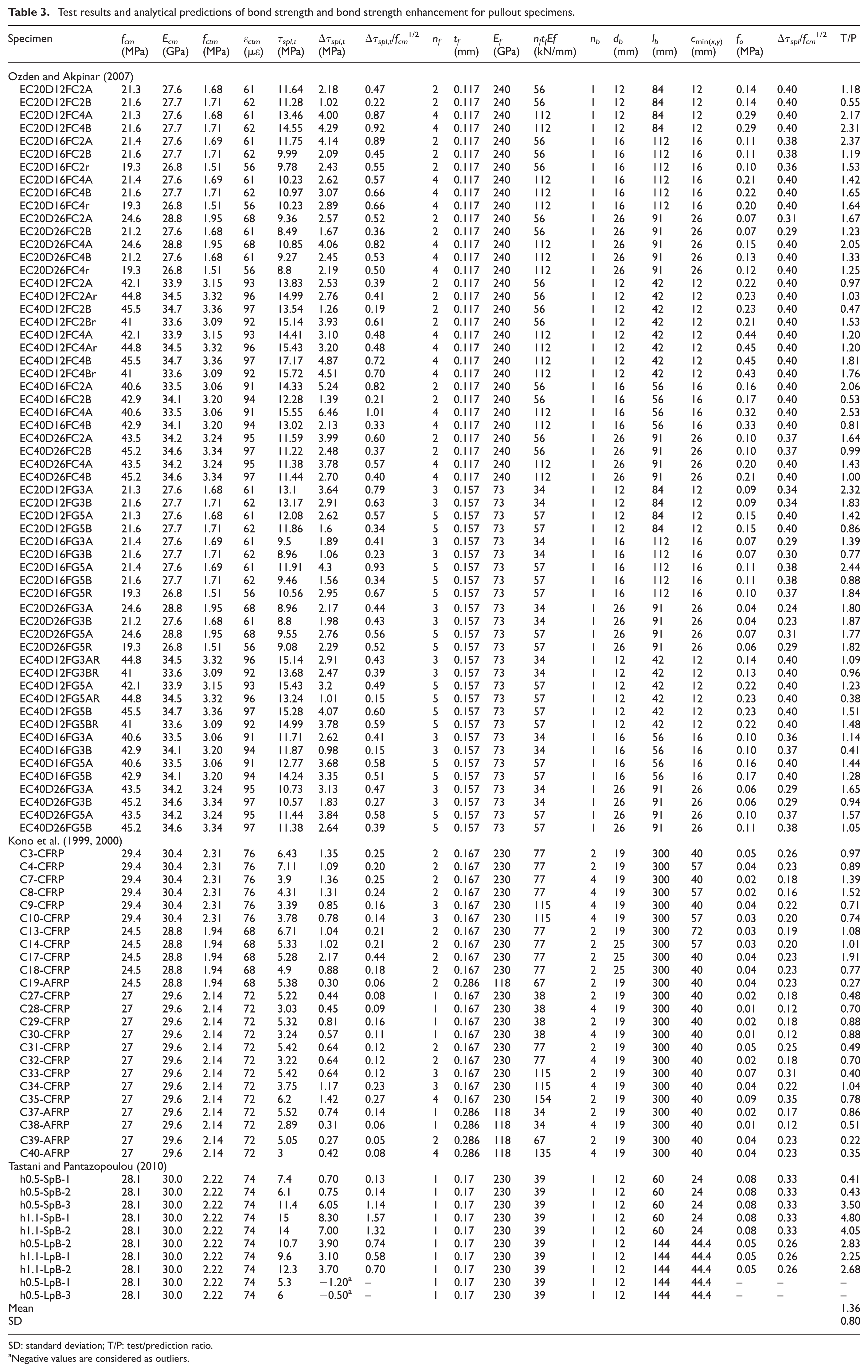
SD: standard deviation; T/P: test/prediction ratio.
Negative values are considered as outliers.
It should be mentioned that the majority of the models described above were calibrated using results from a limited number of tests. However, provided the bond strength contributions from concrete cover and steel stirrups are known, these models seem to accurately determine the types of bond failure observed experimentally (either splitting or pullout, see Figure 8) and that typically dominate the behaviour of substandard lap-spliced members strengthened with FRP. This implies that the amount of FRP required to develop the full capacity of the lapped bars can be readily computed, thus resulting in a more efficient use of FRP reinforcement material and more economical strengthening solutions. The variety of test specimens’ geometries and set-ups that have been used by researchers to date, however, prevents compiling a comprehensive database of experimental results and does not allow for more accurate calibration of existing predictive models and the development of new improved models.
Guidelines for FRP strengthening
Few guidelines provide specific recommendations for the strengthening of substandard lap-spliced columns with externally bonded FRP confinement. For circular columns, the Eurocode 8 part 3 (BSI, 2005), Italian CNR (2012) and Turkish Earthquake Design Code TEC (2007) suggest computing the thickness of the FRP confinement using model 1 in Table 1. These guidelines also extend the use of the same model for rectangular columns implementing the following modifications:
1. In Eurocode 8 Part 3, the section width bw of the rectangular column replaces the diameter D. The confining stress fl is ‘reduced’ by a shape factor ks defined by equation (1) (Mirmiran et al., 1998)
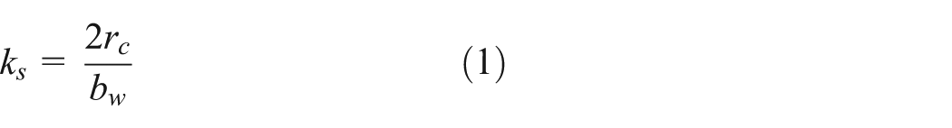
where rc is the corner radius defined in Figure 7.
2. In CNR-DT 200 and TEC (2007), the larger column side replaces the diameter D. In this case, fl is ‘reduced’ using a factor kH (equation (2)) to account for the arching effect shown in Figure 7 (Restrepo and De Vino, 1996)
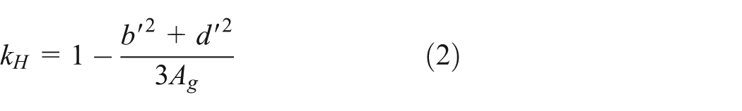
where b′ and d′ are defined in Figure 7 and Ag is the gross sectional area of the column.
While the above-mentioned codes follow a capacity–ductility approach, the Japanese AIJ Guidelines (2002) adopt a bond strength approach to compute the contribution of FRP reinforcement to bond strength using model 13 in Table 1, which is a modified version of the equation originally developed by Fujii and Morita (1983) for internal steel confinement.
Finally, the Greek Code of Structural Interventions (EPPO, 2012) for RC buildings uses a frictional approach (model 14 in Table 1) to design the thickness of the FRP strengthening. The effective FRP strains εfe are calculated using the development of cracks due to ‘an acceptable amplitude’ of slip sd in the lapped bars. The code proposes values sd = 0.3 mm for structures with performance level A (immediate occupancy) and sd = 0.4 mm for levels B and C (life protection and collapse prevention, respectively). The model considers a design limit state as implied by the inclusion of partial safety factors. While the Greek code is adequately progressing towards a general bond strength approach, the adopted model suggests ignoring the contribution of the concrete cover around the lap (λs = 0), which may actually account for most of the existing bond strength of the lap as demonstrated experimentally (e.g. Hamad et al., 2004a, 2004b, 2004c; Hamad and Rteil, 2006; Garcia et al., 2014, 2015).
The comprehensive literature survey in this study indicates that despite the large number of studies available in the literature, existing codes of practice have yet to include more general bond strength approach models. However, it is envisaged that future revisions of the fib Bulletin 14 and Eurocode 8 part 3 (both currently under revision) will include such types of models (e.g. Pantazopoulou et al., 2016).
Summary and conclusions
This article presented a literature survey on substandard lap-spliced members strengthened with external FRP reinforcement. To date, the majority of the studies have adopted a capacity–ductility approach to assess the effectiveness of this strengthening method, focusing on the general performance and enhancements in the capacity and/or ductility of FRP-strengthened columns over original substandard specimens. However, the lack of uniformity of the tested specimens does not enable direct comparisons of results between different experimental programmes. Based on this experimental methodology, some design models were proposed for the FRP strengthening of circular and rectangular columns, but such models may not be easily generalised to account for other cross-sectional geometries.
In contrast, some studies adopt a bond strength approach to examine the basic behaviour of anchorages and lap splices using standard specimens recommended in state-of-the art reports on bond. The effectiveness of the FRP strengthening is usually evaluated by comparing the observed bond strength of unstrengthened and FRP-strengthened specimens. Predictive models adopting a general bond approach are independent of the cross-sectional geometry and compute the total bond strength as the sum of the contributions from concrete cover and internal steel stirrups (if any) and the bond strength enhancement provided by the FRP reinforcement. While these models were calibrated using results from a limited number of tests, they allow determining the amount of FRP required to develop the full capacity of the lapped bars, thus resulting in a more efficient use of FRP reinforcement material and more economical strengthening solutions. It is envisaged that future revisions of the fib Bulletin 14 and Eurocode 8 part 3 (both currently under revision) will include bond strength approach models for design and assessment.
Additional research is considered necessary to provide further understanding of the following aspects:
More results from tests on standard specimens (e.g. beam-end or beam-splice specimens) with different lap splice lengths would provide instrumental insight into the bond behaviour of FRP-confined members. In particular, results from beam-splice specimens can provide suitable bulk data to develop and calibrate more accurate bond strength models.
As the effectiveness of FRP reinforcement in enhancing the bond strength of a lap splice is limited by bar pullout, suggested values for the maximum achievable bond strength enhancement need to be corroborated.
The interaction between bar slippage and FRP strains on full-scale lap-spliced members and the influence of different ratios lb/db on the development of FRP strains need to be investigated.
To date, it is unclear how the different concrete and bar properties, as well as the type of FRP material with different axial stiffnesses, affect the bond strength of anchorages and lap splices in FRP-strengthened members.
The effectiveness of FRP strengthening in improving the behaviour of lap-spliced members with rectangular cross sections and different aspect ratios needs to be studied using more standardised tests to enable direct comparisons.
The effect of type and rate of loading on the behaviour of lapped bars has not been thoroughly investigated.
Footnotes
Appendix 1
Declaration of Conflicting Interests
The author(s) declared no potential conflicts of interest with respect to the research, authorship, and/or publication of this article.
Funding
The author(s) received no financial support for the research, authorship, and/or publication of this article.