
Abstract
In order to improve buildability of cold-formed steel structures, a series of research and development projects have been undertaken by the authors to examine structural behaviour of bolted moment connections between cold-formed steel sections. In this article, a systematic numerical investigation with advanced finite element modelling technique into the structural behaviour of high-strength cold-formed steel lapped Z-sections under gravity loads is presented, and details of the modelling techniques are presented thoroughly. It aims to examine deformation characteristics of these lapped Z-sections with different overlapping lengths. After careful calibration of advanced finite element models of lapped Z-sections against test data, it is demonstrated that the predicted moment rotation curves of these models follow closely the measured data not only up to the maximum applied moments but also at large deformations. In general, all of these lapped Z-sections are unable to resist sustained loadings after section failure under combined bending and shear, and they exhibit sudden unloadings once the maximum applied loads are attained. Hence, the proposed finite element models are able to simulate highly non-ductile deformation characteristics of these Z-sections. While long overlapping lengths over internal supports in multi-span cold-formed steel purlin systems are often advantageous in terms of both ‘stiffness and strength’, more steel materials are used at the same time. Hence, it is very desirable to establish an efficient use of the lapped Z-sections with optimal overlapping lengths. A total of six models with different overlapping lengths are then extended to simulate the structural behaviour of lapped double-span beams, and extensive material and geometrical non-linear analyses have been carried out. It is found that lapped double-span beams with practical overlapping lengths tend to behave superior to continuous double-span beams in terms of both load resistances and deformations. Depending on the overlapping lengths of the lapped Z-sections, different system failure mechanisms have been clearly identified after significant moment redistribution within the beams, and their structural behaviour has been compared in a rational manner. Consequently, these models will be readily employed to investigate the structural behaviour of high-strength cold-formed steel lapped Z-sections under a wide range of practical loading and boundary loading conditions for possible development of effective design rules.
Keywords
Introduction
Over the last three decades, thin gauge steel strips account for over 50% of the annual production of many steel producers in the world. A significant portion of these steel strips is rolled into cold-formed steel sections and sheetings which are adopted and widely used in construction due to their excellent structural efficiency, high versatility in applications and good buildability in construction. Nowadays, cold-formed steel construction has grown into a multi-billion US dollar industry of building products throughout the world.
One of the common applications of the cold-formed steel sections is to act as purlins in metal building envelopes which support metal roof and wall claddings against both gravity and wind loads. Due to their simple geometries and ease of installation, both C- and Z-sections are commonly used. The depths of these sections typically range from 150 to 350 mm, while their thicknesses typically range from 1.2 to 3.2 mm. The yield strengths of the sections are 280 and 350 N/mm2. In the recent years, high-strength cold-formed steel sections with yield strengths at 450 N/mm2 are also available which provide engineered purlin systems with high-load carrying capacities. These sections are attached to metal claddings through various types of fixings to form effective roof and wall systems. Although design rules on their use may be found in various technical recommendations (AISI S100-07:2007, 2007; BS EN 1993-1-3:2006, 2006), full-scale tests on these sections together with fixings and claddings are usually required to assess their performance under both gravity and wind loads (Hancock et al., 2001; Johston and Hancock, 1994; Murray and Elhouar, 1994; Toma and Wittemann, 1994) in order to attain high structural efficiency. In general, understanding the structural behaviour of these purlin and roof systems is extremely important as it is very common to have the same design and construction used repeatedly in millions of tonnes of cold-formed steel sections and claddings.
In general, due to its member configuration, the structural performance of a cold-formed steel purlin system supporting a modern metal roof system (Chung and St Quinton, 1996; Willis and Wallace, 1990; Yu, 2010) is affected by the following restraints:
Intermittent lateral and twisting restraints offered by a roof system at the top flange of the purlin along its member length;
Discrete lateral restraints offered by secondary bracing members to the web of the purlin at intermediate positions along its member length;
Lateral and rotational restraints offered within the lapped sections of the purlin at purlin–rafter connections over supports.
Due to the co-existence of these restraints in the roof system, their combined effects are readily quantified in full-scale system tests, but difficult to be itemized individually. Hence, any change in materials, dimensions and arrangements of cold-formed steel sections and sheetings often require a complete set of full-scale system tests to be carried out for verification and validation on their structural performance (Chung and St Quinton, 1996; Zhang and Tong, 2008). This is very time-consuming and expensive.
It should be noted that in modern building envelopes with metal roof and wall claddings, many components are specifically designed or modified to satisfy various architectural, thermal and water-tightness requirements, and their structural forms are often hampered by the need to accommodate other components and their installation sequences. In the recent years, a large number of modern building envelopes with metal roof and wall claddings have been developed for buildings in which concealed fixings with halters are adopted. These concealed fixings are often developed in such a way to allow the cladding systems to attain high functional performance on water tightness, thermal insulation, and so on, and this often leads to significant penalty in the structural performance (Chung and St Quinton, 1996; Yu, 2010). Hence, the moment resistances of these cold-formed steel purlin members depend significantly on the levels of restraints offered by various attached claddings and other elements of roof systems. Consequently, it is highly desirable to develop scientific tools to assess structural behaviour of cold-formed steel purlin members, and the effects of various restraining effects onto the load-bearing deformation characteristics of the purlin members should be properly accounted for.
In this article, a systematic numerical investigation with advanced finite element modelling technique into the structural behaviour of cold-formed steel lapped Z-sections is presented. It aims to examine deformation characteristics of these lapped Z-sections with different overlapping lengths.
Previous investigation on structural stability of purlin members
In general, cold-formed steel sections are open, and thin sections which are torsionally weak and highly susceptible to lateral instability. Due to the geometry of cold-formed steel sections, their structural performance is very different to those of hot-rolled steel I-sections and channels (Hancock et al., 2001; Yu, 2010):
In a C-section, the shear centre of the cross section does not coincide with its centriod, and thus, it is normally subjected to combined bending and torsion in the presence of lateral loads;
In a Z-section, the principal axes of the cross section do not coincide with their centroidal axes, and thus, it is normally subjected to bi-axial bending in the presence of lateral loads.
A comprehensive test series of cold-formed steel C-sections under combined bending and torsion was reported by Put et al. (1999a). A complementary numerical study was also reported by Pi et al. (1998), and a realistic finite element model was developed to investigate the elastic lateral–distortional buckling, the inelastic behaviour, and the moment resistances of C-sections in the presence of residual stresses and initial imperfections. The effects of moment distribution and load height on the lateral–distortional buckling resistances were also studied. Similar investigations on the lateral instability of cold-formed steel Z-sections under bi-axial bending were also reported by Put et al. (1999b). However, it should be noted that the dimensions of these C-sections are rather small, that is, 102 mm (D) × 53 mm (B) × 1.0 or 1.9 mm (t), and it is necessary to extend these models to incorporate practical loading conditions in purlin systems in which the actions of the wind loads are applied through claddings and then through different attachments and fixings, such as halters and screws, onto the top flanges of these sections.
Previous investigation on structural stability of purlin systems
It is essential to investigate into lateral instability of partially restrained cold-formed steel purlin systems in which loads are applied to top flanges of the sections in the presence of different restraining effects offered by various components in the roof systems. Hence, both the support and the restraint conditions of these sections should be properly incorporated into analysis and design.
It should be noted that the beneficial effects of intermittent lateral restraints provided by attached roof claddings have been long identified, and the mechanism is well understood (Chung and St Quinton, 1996; Gajdzicki and Goczek, 2015; Gao and Moen, 2012; Ghosn and Sinno, 1996; Hancock et al., 1993; Rousch and Hancock, 1997; Toma and Wittemann, 1994). Many attempts have been made over the years to incorporate this effect to increase the load carrying capacities of purlin members with some success. The effect of discrete lateral restraints provided by secondary bracing members is often simplified by assigning full positional restraints to the purlin members during numerical modelling. Such simplification may be adopted in practice, although these secondary bracing members may not be fully effective due to lack of fit, bolt slippage, misalignment or even buckling under compression. Moreover, the benefits of strength and stiffness enhancement in the overlapped sections over internal supports and of reduced unrestrained lengths of the Z-sections are often neglected for simplicity. Hence, the effect of the longitudinal rotational restraints offered by lapped Z-sections at purlin–rafter connections is often simplified conservatively. Only continuous sections are incorporated instead by some researchers (Lucas et al., 1997a, 1997b).
In order to promote the effective use of cold-formed steel sections in building construction, a series of research and development projects have been undertaken by the authors to study the structural behaviour of multi-span purlin systems using high-strength cold-formed steel sections with overlaps. It should be noted that over the years, 6 test series with a total of 26 single-point load tests on lapped Z-sections were carried out to investigate the structural behaviour of the lapped Z-sections (Ho and Chung, 2004 and Chung and HO, 2004), and the test results have been successfully employed to evaluate the effective flexural rigidities, EIeff, of lapped Z-sections with bolted moment connections of different configurations (Chung and Ho, 2005). Hence, adoption of the effective flexural rigidities of these lapped Z-sections over internal supports enables rational design of high-strength cold-formed steel multi-span purlin systems under both gravity and wind loads (Ho and Chung, 2006). Consequently, it is considered to be highly beneficial to develop effective numerical models on both continuous Z-sections and lapped Z-sections with various overlapping lengths in order to analyse their structural behaviour with sufficient structural adequacy. The numerical results will be readily adopted for subsequent development of rational design rules.
Failure mechanism of fully restrained multi-span purlin systems
According to both experimental and numerical investigations carried out by the authors (Chung, 2004; Chung and St Quinton, 1996), it was proposed that typical failure mechanism of a fully restrained double-span purlin system using continuous Z-sections may be divided into the following stages, as shown in Figure 1:
Linear elastic stage. Under a small applied load, w (kN/m), the purlin system behaves in a linear elastic manner. As the applied load increases, the corresponding hogging moment over the internal support reaches the section failure resistance of the Z-section under combined bending and shear. The first ‘partial strength hinge’ is then formed.
Non-linear stage with moment redistribution. On further increase in the applied load, the purlin system undergoes a non-linear deformation with significant moment redistribution, and a large rotational deformation of the purlin will take place over the internal support according to the residual moment resistance of the failed Z-section. Hence, the applied moment over the internal support will be readily distributed towards the mid-span of each purlin member until formation of the second ‘partial strength hinge’.
System failure with large deformation. During moment redistribution, the purlin system will act partially as a double-simply supported beam with a residual moment resistance over the internal support under any additional load. System failure will take place when the maximum sagging moment near mid-span of the purlin member reaches the moment resistance of the Z-section.
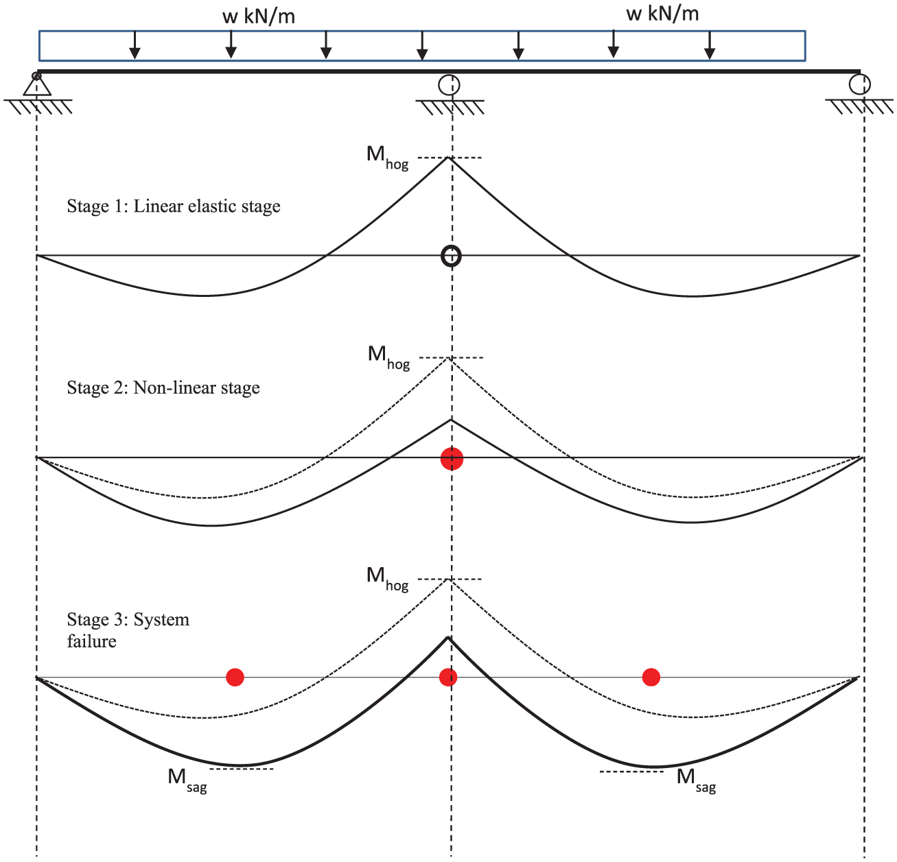
Failure mechanism of a continuous double-span purlin system.
However, few experimental investigations into the structural behaviour of lapped double-span purlin systems were found in the literature. While the overall deformation characteristics of a lapped double-span purlin system are expected to follow broadly to those of a double-span purlin system with continuous purlin sections, the effect of lapped Z-sections with different overlapping lengths should be quantified experimentally and numerically. It should be noted that the term ‘partial strength hinge’ is adopted above instead of the term ‘plastic hinge’ because of lack of rotational ductility in cold-formed steel Z-sections.
Finite element modelling
A number of finite element models on cold-formed steel and stainless steel sections have been reported in the literature (Ashrafa et al., 2006; Bakker and Pekoz, 2003; Chung, 2004; Dinis and Camotim, 2010; Li, 2004; Lucas et al., 1997a, 1997b; Telue and Mahendran, 2004; Ye et al., 2004; Zhou and Young, 2007) over the years with different levels of detailing and accuracy on element formulations, material models, cross-sectional definitions and mesh configurations. Moreover, various methods on detailed modelling on both support and loading conditions of purlin systems using C- and Z-sections have been proposed, depending on availability of suitable finite elements and computing resources. Experiences and insights from these researchers in finite element modelling have been studied carefully for possible adoption in this study.
In general, the thin degenerated four-noded shell element, namely, Element S4R, is commonly employed by many researchers in their finite element models to examine the structural behaviour of cold-formed steel sections against various interactive modes of local buckling, distortional buckling and overall lateral buckling. However, most of these studies are found to focus on the structural behaviour of these sections under their maximum loads while little effort is made to examine their post-buckling behaviour at large deformations.
Objectives and scope of work
In order to improve buildability of cold-formed steel structures, a series of research and development projects have been undertaken by the authors to examine structural behaviour of various forms of bolted moment connections between cold-formed steel sections. It should be noted that six test series with a total of 26 single-point load tests on lapped cold-formed steel Z-sections were carried out by the authors to investigate structural behaviour of the lapped connections. Full details of the experimental investigation may be found in the literature (Chung and Ho, 2005; Ho and Chung, 2004).
In this article, a systematic numerical investigation with advanced finite element modelling technique into the structural behaviour of cold-formed steel lapped Z-sections is presented. It aims to examine deformation characteristics of these lapped Z-sections with different overlapping lengths. As a whole, the numerical investigation takes the following forms of activities:
To establish finite element models of lapped Z-sections with different overlapping lengths under single-point loads;
To calibrate these models against test results of the test series mentioned above;
To develop finite element models of lapped double-span purlin systems using cold-formed steel Z-sections with different overlapping lengths;
To examine structural behaviour of the purlin systems, identify various modes of failure and determine structural advantages of these systems over purlin systems with continuous Z-sections.
The areas of interest in this numerical investigation include the following:
Detailed modelling of the overlapping zone (with contact elements) of lapped Z-sections;
Section failure of Z-sections under combined bending and shear;
Load deflection curves of lapped Z-sections, especially at large deformations;
Overall structural behaviour of lapped double-span purlin systems, in particular, moment redistribution over internal supports.
Reference tests
A total of six tests on pairs of simply supported Z-sections with different overlapping lengths are adopted in this study as reference tests for calibration of the proposed finite element models (Ho and Chung, 2004). In all these tests, a generic lipped Z-section is adopted which is commonly referred as section Z15016 G450. It should be noted that section Z15016 denotes a lipped Z-section with a section depth of 150 mm and a thickness of 1.6 mm, and G450 denotes a nominal yield strength at 450 N/mm2. Table 1 summarizes the test programme and the measured cross-sectional dimensions of the Z-sections together with measured mechanical properties of the steel materials.
Summary of test programme and data.
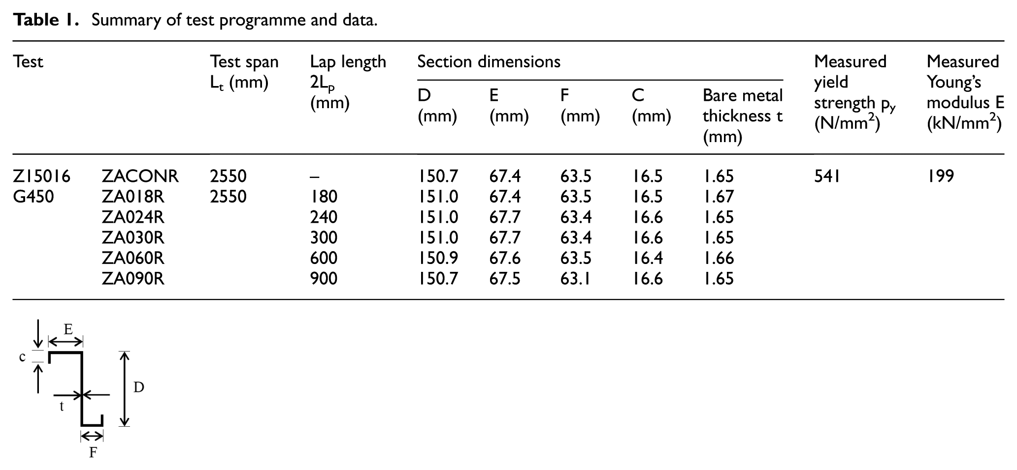
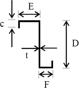
Figure 2 illustrates a typical test set-up of the single-point load tests on the lapped Z-sections. It is shown that in each test, a pair of nominally identical Z-sections is tested in a simply supported condition under an applied load at mid-span. In order to provide restraints to the Z-sections, steel strips are provided as interconnections to the Z-sections at regular intervals, and they are connected to both the top and the bottom flanges of the sections with screws. Moreover, wooden blocks are also provided between the section webs, and they are securely attached with screws. The load is applied directly to the webs of the Z-sections through bolts.
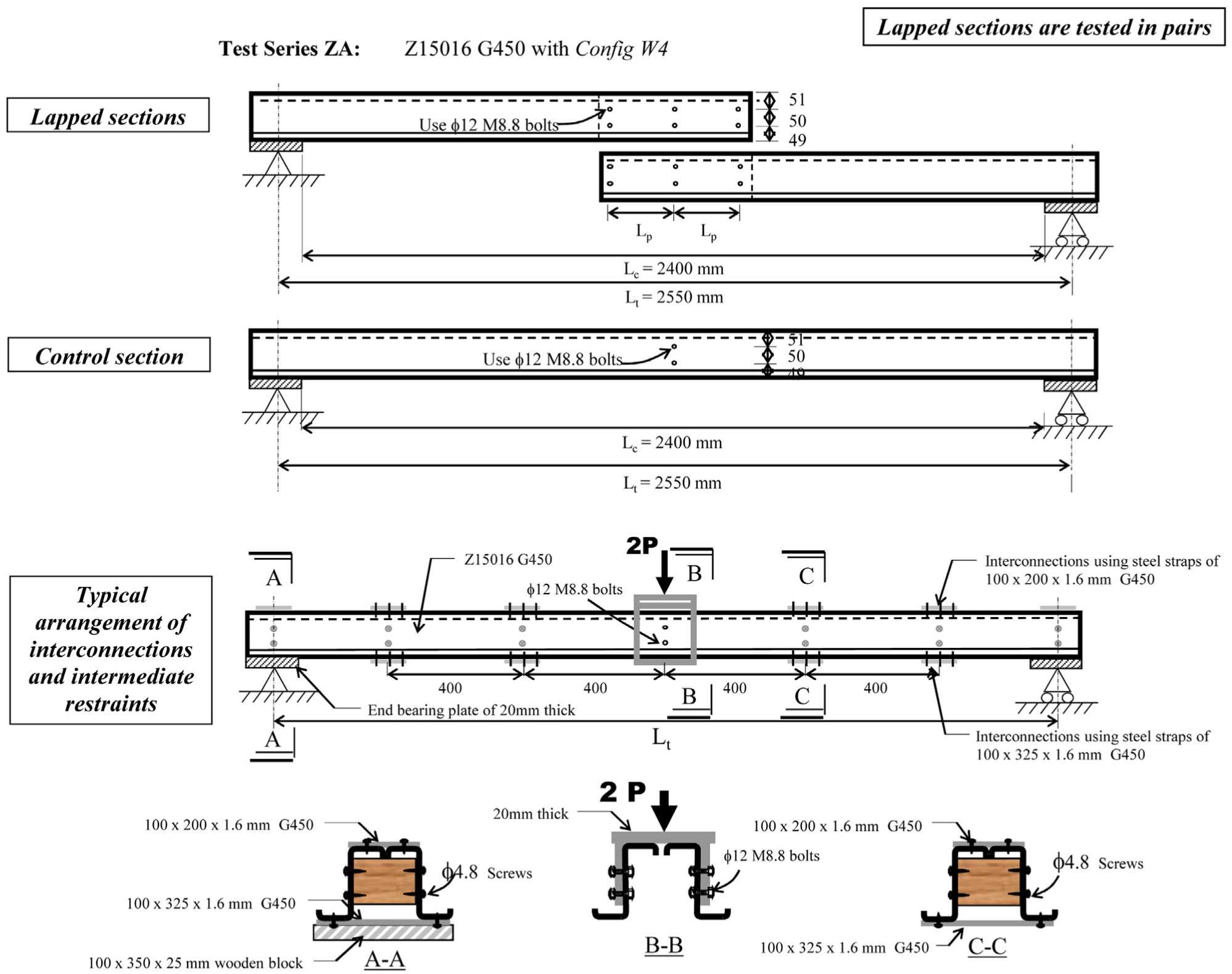
Typical set-up of single-point load tests on lapped Z-sections.
The maximum applied load, the observed mode of failure and the corresponding deformation characteristics of each of the tests are presented in Table 2. It should be noted that in all tests, section failure of the Z-sections under combined bending and shear is observed, as shown in Figure 3. The moment rotation curves obtained from the tests are presented in Figure 4 for easy reference. In general, all of these curves show a sudden unloading after section failure. Hence, the lapped Z-sections are unable to resist sustained loadings, and they exhibit highly non-ductile deformation characteristics after section failure.
Summary of test results.
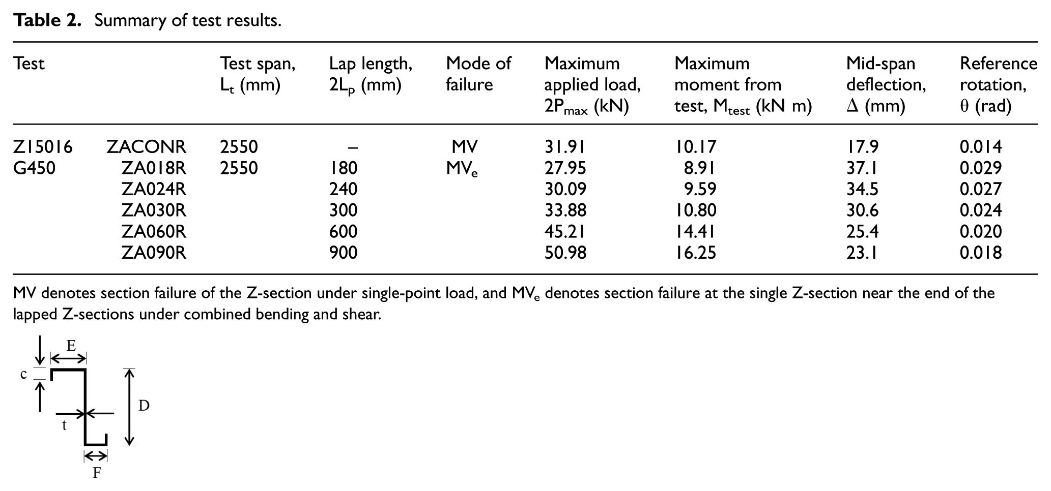
MV denotes section failure of the Z-section under single-point load, and MVe denotes section failure at the single Z-section near the end of the lapped Z-sections under combined bending and shear.

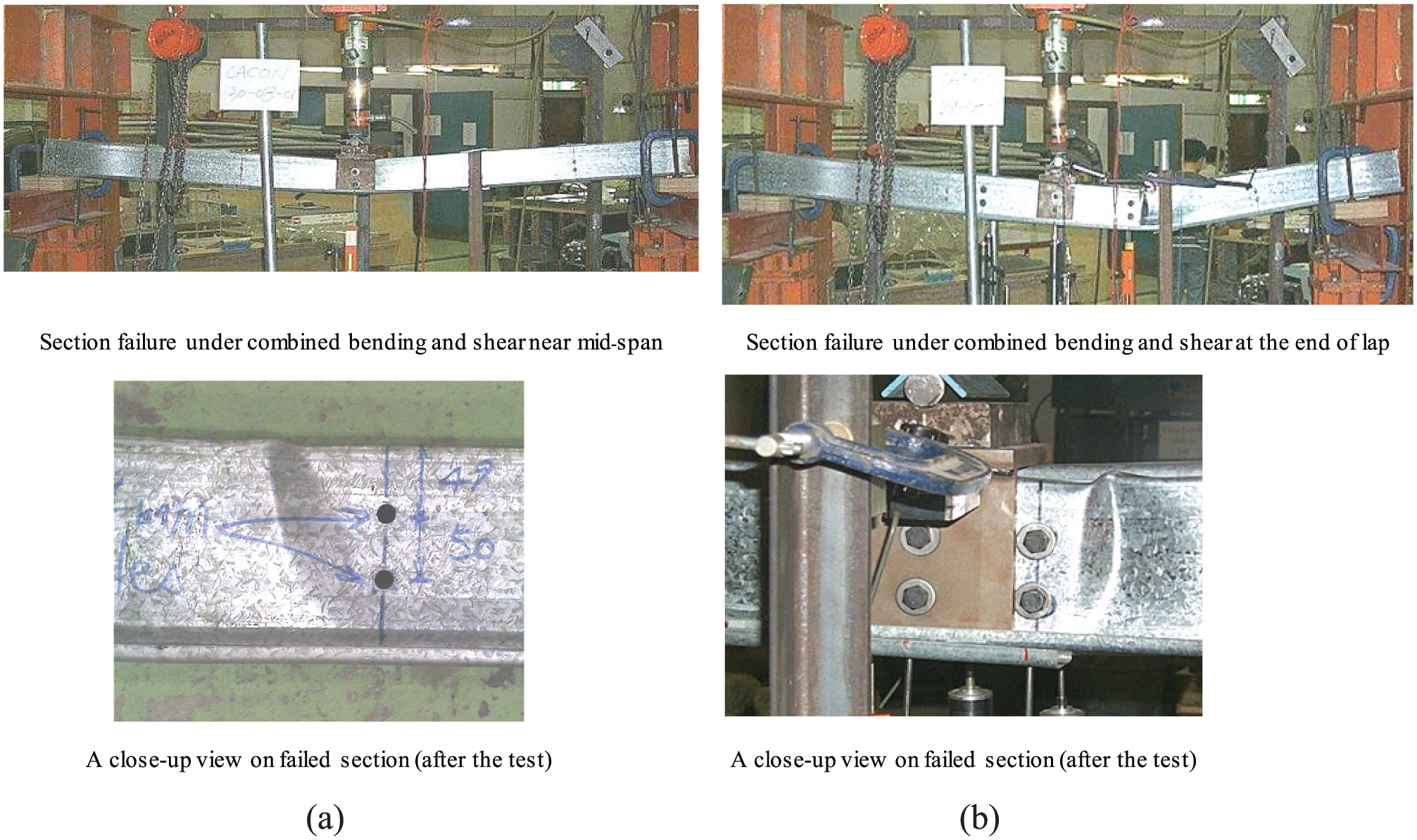
Various modes of failure in single-point load tests on lapped Z-sections: (a) test ZACONR and (b) test ZA090R.
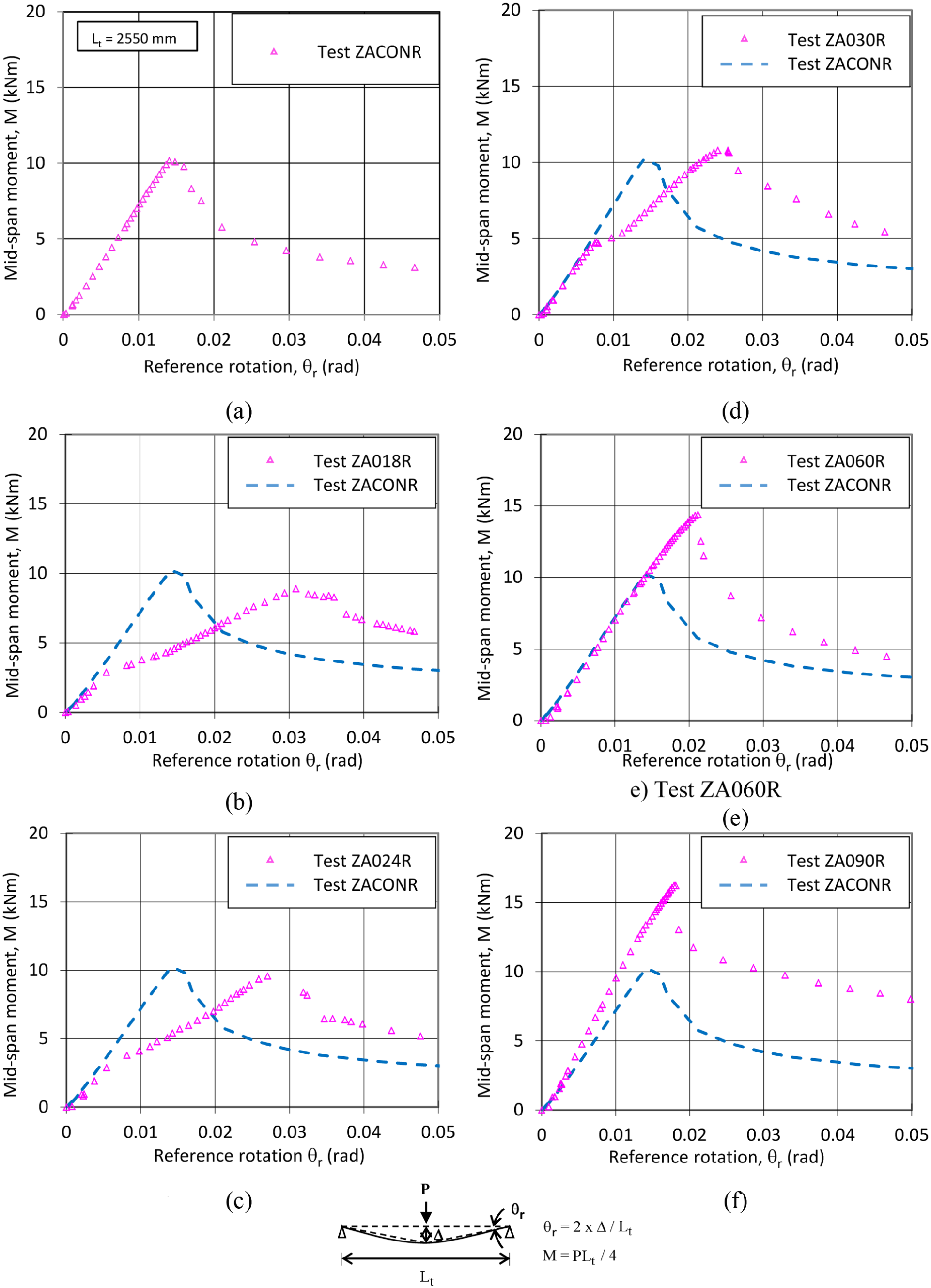
Measured moment rotation curves of single-point load tests on lapped sections: (a) test ZACONR, (b) test ZA018R, (c) test ZA024R, (d) test ZA030R, (e) test ZA060R and (f) test ZA090R.
It should be noted that the observed mode of failure may be generally described as a combination of the following:
Local buckling in the plate element of the cross section under compression;
Distortional buckling in the cross section under bending;
Overall lateral and twisting deformation of the member under combined bi-axial bending and torsion.
Due to the presence of the interconnections provided at regular intervals along the spans of the Z-sections, lateral and twisting deformations of the Z-sections at the interconnections are effectively eliminated while local buckling and cross-sectional distortional buckling in the Z-sections between the interconnections are apparent. The levels of restraint provided to the Z-sections in the tests are adopted for calibration of the proposed finite element models.
Finite element modelling
The general finite element package, ABAQUS (version 6.13), is adopted in this study, and advanced finite element models with both material and geometric non-linearity (ABAQUS, 2013; Ashrafa et al., 2006; Bakker and Pekoz, 2003; Chung, 2004; Telue and Mahendran, 2004; Young and Yan, 2002) are established to simulate the deformation characteristics of lapped Z-sections with different overlapping lengths. Figure 5(a) illustrates typical finite element models of the lapped Z-sections with sections Z15016 G450 under the test conditions. It should be noted that different types of finite elements are employed to model the Z-sections, interconnections, screw fixings and interfaces between the Z-sections and the interconnections. Key features of the finite element models are described in the following.
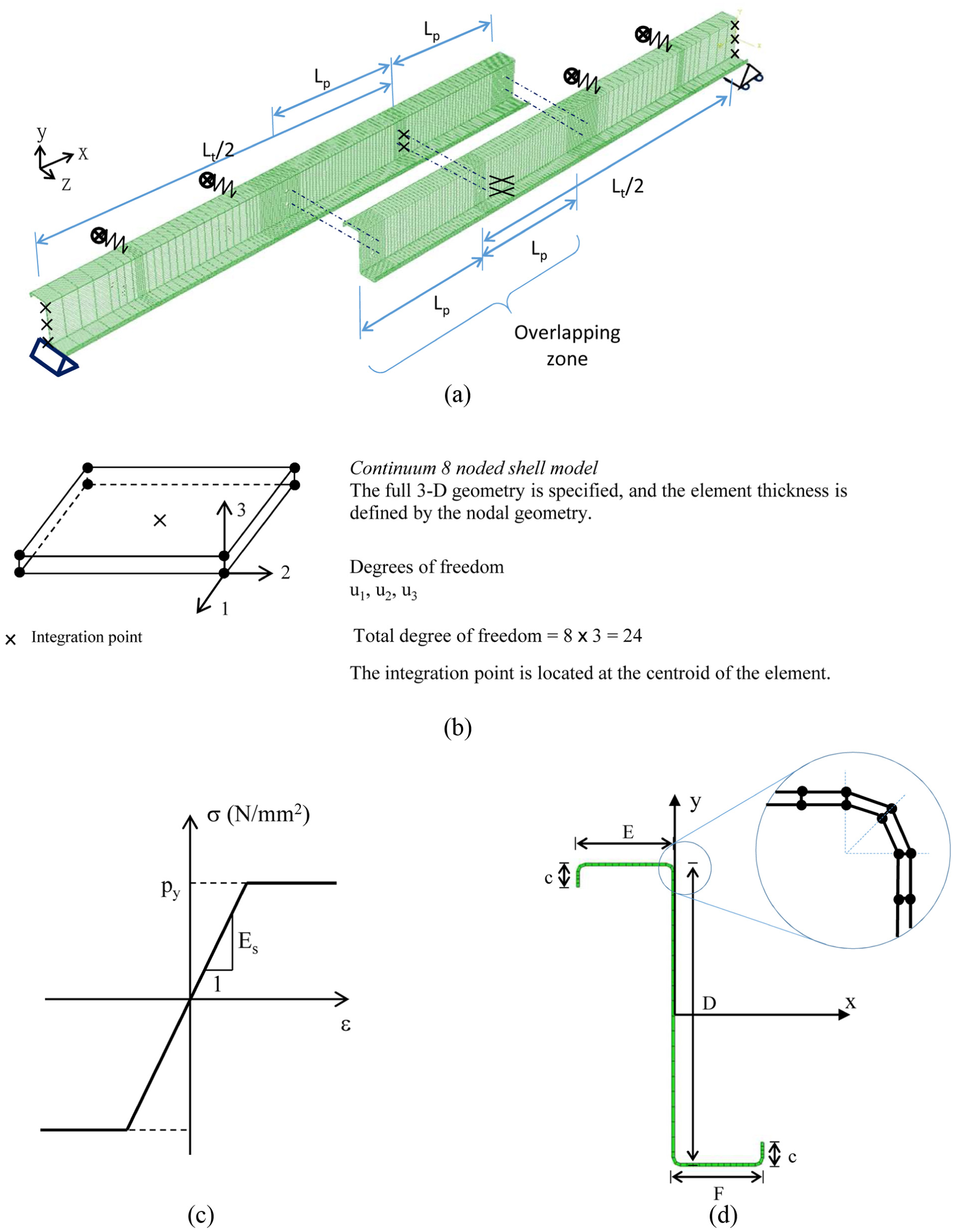
Typical finite element model of lapped Z-sections under single-point loads: (a) typical finite element model layout of lapped Z-sections, (b) details of shell element SC8R, (c) idealized bi-linear stress–strain curve and (d) definitions of the cross section of a Z-section.
Material model
As shown in Figure 5(c), a bi-linear stress–strain curve according to the measured mechanical properties of the Z-sections is adopted in the numerical analyses. It should be noted that
Both the yield strength and Young’s modulus were obtained from standard coupon tests on steel strips cut from the webs of the Z-sections, and the material properties of these steel sections are presented in Table 1;
For simplicity, the effect of residual stresses in the cross sections in both flat elements and rounded corners due to cold working is neglected. Nevertheless, the yield strengths of the rounded corners in the cross sections are assigned to be 1.05py, where py is the measured yield strength of the Z-sections. In general, these two effects are considered to have relatively minor effects on the buckling behaviour of the Z-sections.
Shell element
In order to simulate both in-plane and out-of-plane deformations of the Z-sections undergoing significant material yielding and geometrical buckling, a continuum eight-noded shell element, namely, SC8R, as shown in Figure 5(b), is adopted in this study due to its good structural accuracy at large deformations. It should be noted that
As each node has three translational degrees of freedom, the total degrees of freedom in one element are thus 24. Unlike a conventional shell element which discretizes a reference surface, this element discretizes an entire three-dimensional body with its full geometry specified by the co-ordinates of the nodes;
The effects of transverse shear deformation and thickness change have been fully incorporated into the formulation of the element for accurate prediction of finite membrane deformations and large rotations;
As the element may readily be stacked to provide more refined through-thickness responses, it allows accurate prediction on transverse forces as well as through-thickness pinching forces.
Thus, the element is highly appropriate for non-linear three-dimensional geometric analyses of thin-walled sections under both in-plane and out-of-plane loadings. Figure 5(d) illustrates the definitions of the cross sections of the Z-sections using shell element SC8R, and it should be noted that two elements are used to model the round corners of the cross sections as trimmed corners for simplicity.
Loading and support conditions
A typical finite element model is shown in Figure 6(a), and it should be noted that
The lapped Z-sections are supported with fixed supports at their left ends and roller supports at their right ends, and these boundary conditions are applied to the bottom flanges of the Z-sections at supports rather than at their mid-height in order to correspond directly to the test conditions;
The applied load in each model, that is, the total applied load, is taken as 2P, and hence, the applied load to each of the Z-sections is P only; the applied load is then further divided into four quarters, that is, four numbers of P/4, and each of them is shared equally to all the nodes around a bolt hole in the section web through a set of ‘radial’ springs; all of these springs are assigned to have a high compressive stiffness at 1000 kN/mm, but a low tensile stiffness at 0.001 N/mm. The use of the ‘radial’ springs allows consistent load distribution among all the nodes around the bolt holes in the section webs; local-bearing deformation in the webs around the bolt holes is not modelled in this investigation for simplicity;
Lateral restraints are provided as interconnections to both the top and the bottom flanges of the sections, and typical values of the restraint stiffnesses given in the literature (Fan et al., 1997; Rogers and Hancock, 1999) are adopted.
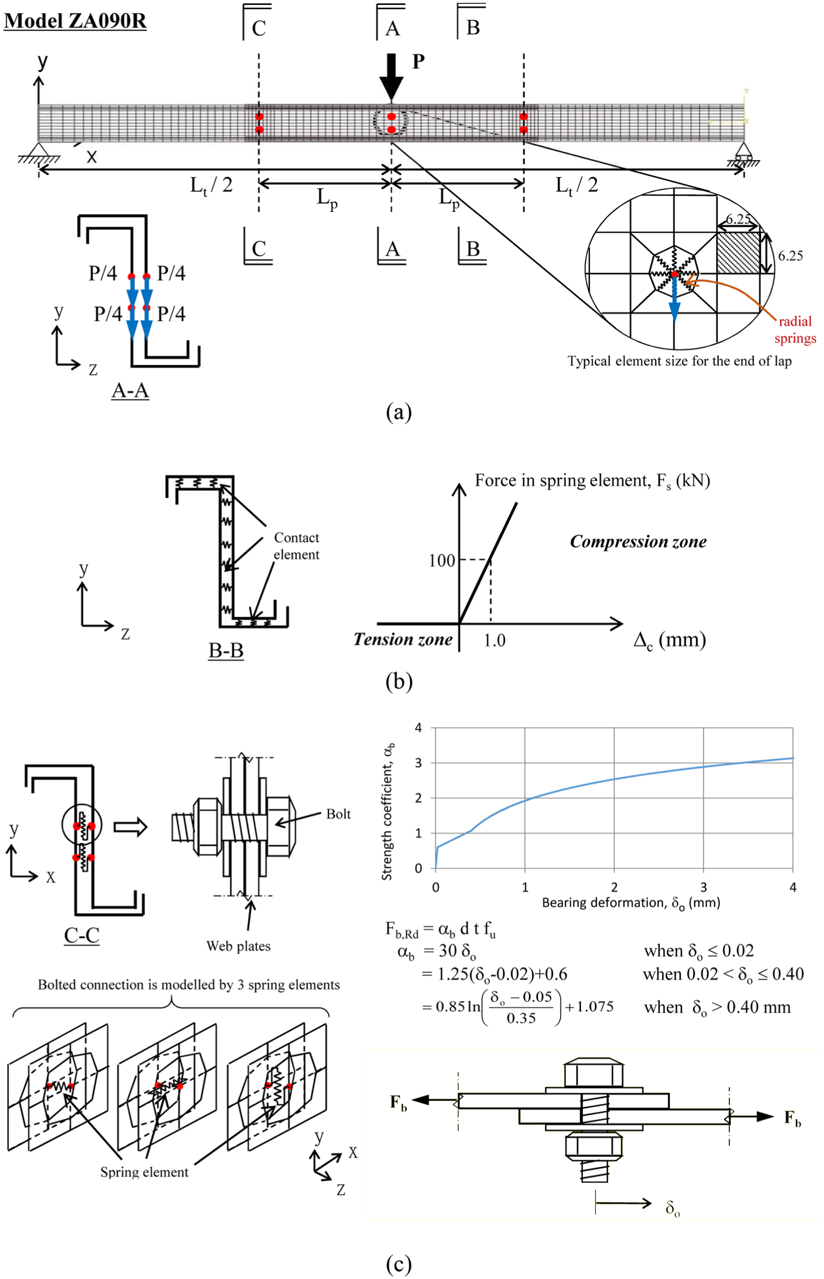
Details of loading and boundary conditions of finite element models of lapped Z-sections: (a) overall layout and meshing of lapped sections, (b) details of contact properties between the lapped Z-sections over the entire overlapping zone and (c) modelling details of bolted connection.
Modelling of overlapping zones
In order to model accurately the overlapping zones of the Z-sections, the contact areas between the Z-sections are carefully modelled (Zhou and Young, 2007), as shown in Figure 6(b), as follows:
Contacts between the cross sections of the Z-sections within the overlapping zones are modelled with ‘radial’ spring elements, namely, SPRING2, with a high compressive stiffness at 1000 kN/mm, but a low tensile stiffness at 0.001 N/mm, so that mesh intrusion is prevented effectively;
A high compressive force will be induced only in the pre-defined direction of the spring element during deformation, and hence, no force will be induced in any other direction.
During the model development, a number of advanced contact elements have been employed to model the contact surfaces. However, it is found that in some cases, numerical convergence is difficult to achieve as there are a large number of contact elements in the overlapping zones which may undergo various possible deformations during iterations, leading to numerical instability. Instead, the use of spring elements is found to be very successful in eliminating numerical instability during analyses of the lapped Z-sections.
Finite element mesh
The finite element mesh of the lapped Z-section under a simply supported condition is illustrated in Figure 6(a). In order to establish a finite element model with optimal structural accuracy and numerical efficiency, a sensitivity exercise on the mesh configurations was carried out. The mesh adopted for this study shown in Figure 6(a) comprises a total of 36,318 nodes and 18,108 elements. It should be noted that
The element size is typically 10 × 25 mm2 and 12.5 × 25 mm2 for the flange and the web elements of the Z-sections, respectively, and thus, the aspect ratios of these elements are successfully kept between 2.0 and 2.5;
The mesh is refined locally in the mid-span regions of the Z-sections as well as at the points of interconnection so that the aspect ratios of these elements are kept between 1.0 and 1.25.
Modelling of bolted interconnections
In order to model accurately the bolted connections of the Z-sections within the overlapping zone, the bolted connections are carefully modelled, as shown in Figure 6(c), as follows:
All the bolted connections are modelled with spring elements of different stiffnesses along three perpendicular directions, namely, kix, kiy and kiz, which are estimated by the load-bearing deformation characteristics of the bolted connection as shown in Figure 6(c).
The load-bearing deformation characteristics of the bolted connections may be well described with the use of αb which is a non-linear function of a bearing deformation, δo.
The values of various translational restraints are adopted from the test results of various lapped shear tests of screwed connections with steel strips of different thicknesses and yield strengths reported in the literature (Chung and Ip, 2000).
Initial geometrical imperfection
In general, it is necessary to provide initial geometrical imperfections in the models to facilitate smooth transition across bifurcation limits during equilibrium iterations in order to avoid numerical divergence. Although this is not necessary in this case as the Z-sections will deflect laterally and twist longitudinally under bi-axial bending and torsion, it is considered to be appropriate to incorporate initial geometrical imperfections into the models as part of a standard procedure of numerical modelling. Hence, elastic linear eigenvalue analyses on the Z-sections under single-point loads at mid-span are performed, and the deformed mode shapes at first bifurcation, that is, the eigenmodes corresponding to the lowest eigenvalues, are extracted. The eigenmodes are then superimposed to the perfect geometries of the Z-sections as initial geometrical imperfections, and the magnitude of the maximum out-of-plane initial imperfections is taken to be 0.25 t, where t is the thickness of the Z-sections. The initial geometrical imperfections of typical models are illustrated in Figure 7.
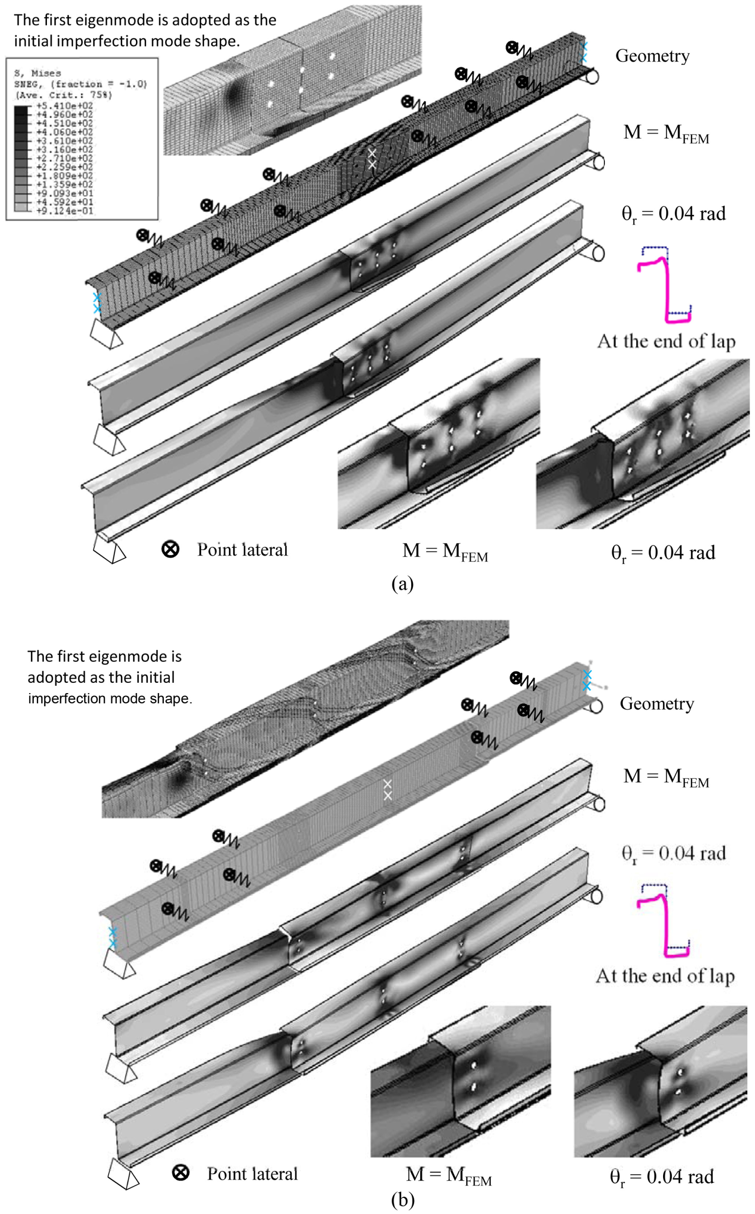
Numerical analyses and results of models ZA018R and ZA090R: (a) finite element mesh and deformed shapes of model ZA018R under various applied loads and (b) finite element mesh and deformed shapes of model ZA090R under various applied loads.
Calibration of finite element models
It should be noted that a total of six models with different overlapping lengths have been established, and material and geometrical non-linearity analyses in all these models have been successfully completed. Typical deformed shapes of the models under the maximum applied moments are illustrated in Figure 7. The failure mode of the lapped Z-sections may be well described as interactive local plate buckling and cross-sectional distortional buckling near the end of the overlapping zone. Moreover, deformed shapes of both models at large deformations are also presented in Figure 7, and extensive plastic buckling in the Z-sections near mid-span is apparent. These are found to correspond closely to the observed deformations of the Z-sections in the tests after failure.
Both the measured and the predicted moment rotation curves of each of the six tests are plotted onto the same graphs in Figure 8 for easy comparison. It is demonstrated that the predicted moment rotation curves of these models follow closely the measured data not only up to the maximum applied moments but also at large deformations. Hence, the highly non-ductile deformation characteristics of these lapped Z-sections have been successfully captured with the models.
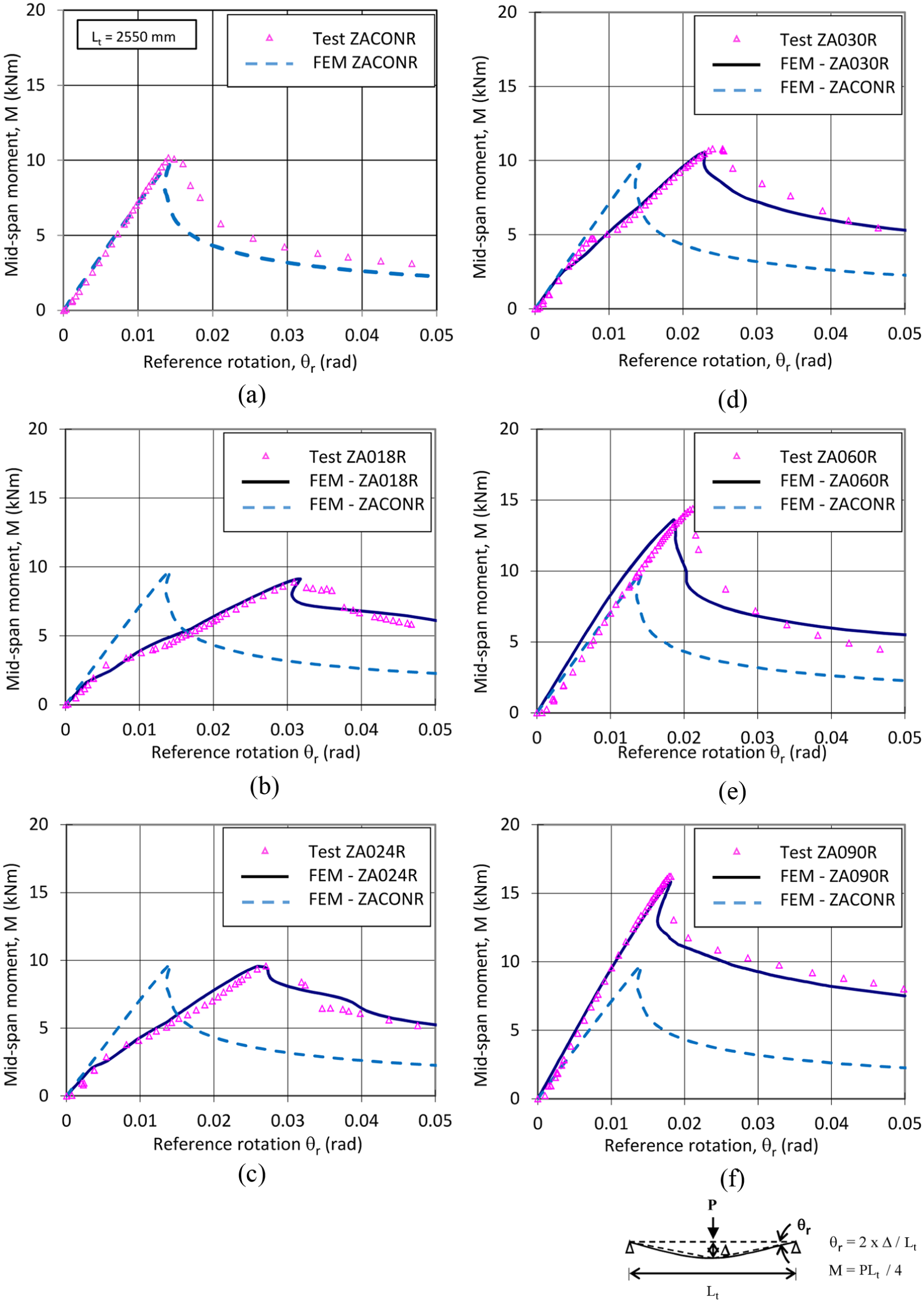
Moment rotation curves of lapped Z-sections: (a) test ZACONR, (b) test ZA018R, (c) test ZA024R, (d) test ZA030R, (e) test ZA060R and (f) test ZA090R.
Model factors
Table 3 summarizes both the measured and the predicted moment resistances of the six lapped Z-sections. In order to access structural accuracy of the models, a model factor (MF) is established which is defined as follows
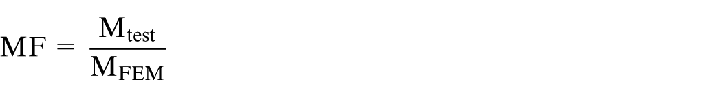
where Mtest is the measured moment resistance of a lapped Z-section obtained from a test and MFEM is the predicted moment resistance of the corresponding finite element model of the lapped Z-section.
Summary of numerical results.
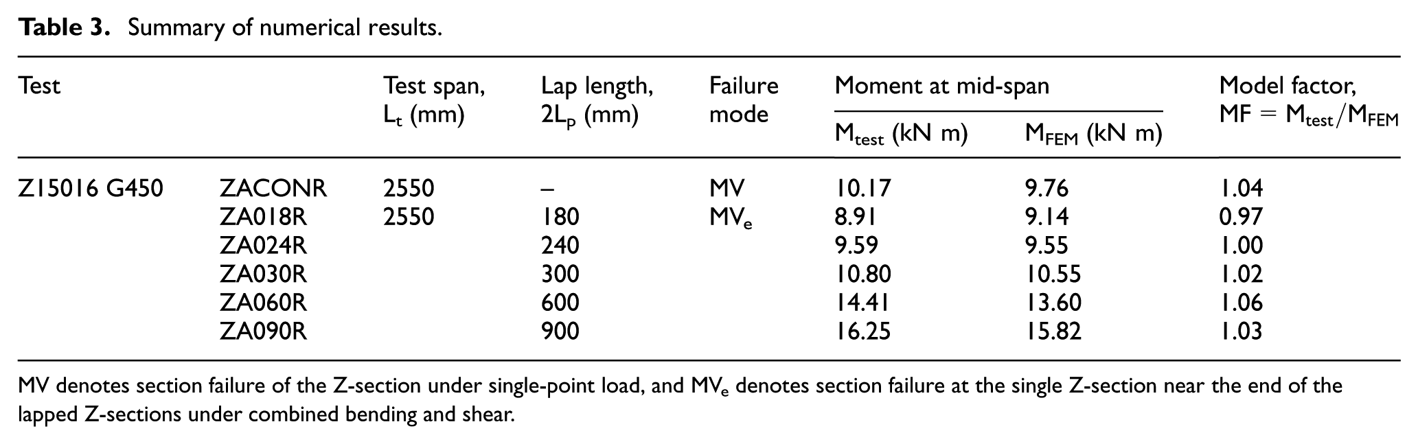
MV denotes section failure of the Z-section under single-point load, and MVe denotes section failure at the single Z-section near the end of the lapped Z-sections under combined bending and shear.
It should be noted that the value of MF should be larger than unity if the model is conservative, that is, the predicted moment resistance is smaller than the measured value. In general, the values of MF should range from 1.0 to 1.2 for conservative and yet efficient models. All the MFs for the finite element models are summarized in Table 3 for easy comparison. It is shown that the MFs in assessing the moment resistances of all the six models are found to range from 0.97 to 1.06 with an average value of 1.03. Moreover, for those finite element models with practical overlapping lengths, that is, models ZA030R, ZA060R and ZA090R, together with the model of the control test, that is, model ZACONR, the average MF is 1.04. Hence, all these models are considered to be effective in predicting the structural behaviour of the Z-sections at failure.
Modelling of double-span purlin systems
While long overlapping lengths over internal supports in multi-span cold-formed steel purlin systems are often advantageous in terms of both ‘stiffness and strength’, more steel materials are used at the same time. Hence, it is essential to establish an efficient use of the lapped Z-sections with optimal overlapping lengths. This is readily achieved through a comprehensive comparison among the deformation characteristics of various models.
Double-span beam models
In order to examine the structural performance of multi-span cold-formed steel purlin systems under gravity loads, a total of six different double-span beam models with section Z15016 G450 have been established as follows:
Continuous beam model. There is only one model in which the Z-section is continuous over the internal support, and it is refereed as model DSB. The finite element mesh together with the loading and boundary conditions of the double-span system is shown in Figure 9(a). The deformation characteristics of the model may be readily taken as a reference when assessing those of the models with various overlapping lengths.
Lapped beam models. Five different double-span beam models have been established whose overlapping lengths are taken as 4D, 5D, 6D, 7D and 8D (where D is the depth of the Z-section), and they are referred as models DSB-4D, DSB-5D, DSB-6D, DSB-7D and DSB-8D, respectively. Typical mesh together with the loading and boundary conditions of the double-span system is shown in Figure 9(b).
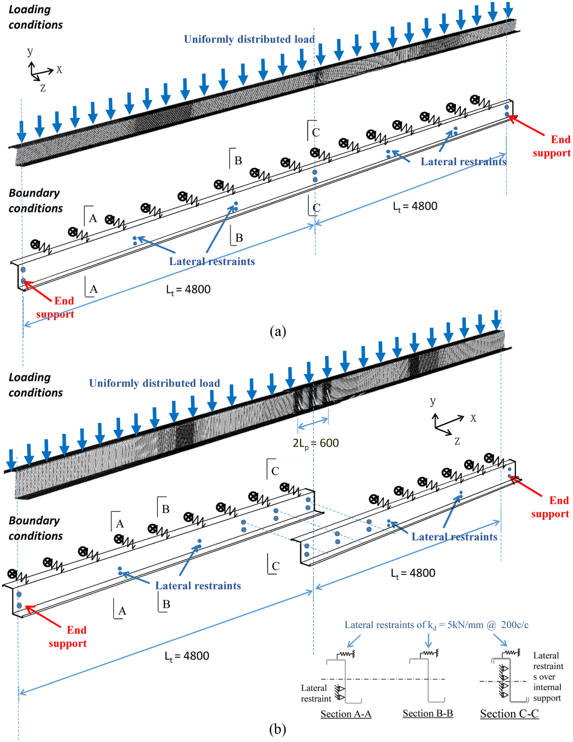
Double-span beams: (a) double-span continuous beam model DSB and (b) lapped double-span beam model DSB-4D.
It should be noted that
Lateral restraints, kd, are provided at regular intervals to the top flanges of the models, as shown in Figure 9, and these two restraints are readily offered to the Z-sections by attached roof claddings in practical purlin-supported roof systems. Typical value of these restraints at 5.0 kN/mm provided at an interval of 200 mm along the beam span (Fan et al., 1997; Rogers and Hancock, 1999) is adopted in this study.
Full lateral restraints are also provided at one-third span of the Z-sections according to common practice in cold-formed steel purlin systems, as shown in Figure 9, and their presence has significant effects on lateral stability of the Z-sections whenever compression flanges of these Z-sections are unrestrained.
Data analysis
In general, due to the highly non-ductile deformation characteristic of the lapped Z-sections after section failure, significant moment redistribution within the models takes place, leading to some degrees of difficulty in numerical convergence. Nevertheless, all the models for both continuous and lapped double-span beams have been successfully analysed under gravity loads. Typical deformed shapes of models DSB, DSB-4D, DSB-6D and DSB-8D are shown in Figures 10 to 13, respectively, while those of models DSB-5D and DSB-7D are not shown for simplicity. It should be noted that
Model DSB. As shown in Figure 10, the first ‘partial strength hinge’ in this model is formed at the cross section directly over the internal support as both applied hogging moments and shear forces attain their maximum values. Due to significant reduction in the moment resistance of the Z-section at large rotations, moment redistribution takes place sharply within the beam, and two additional ‘partial strength hinges’ are formed near the mid-span of each of the span of the beam, leading to a systematic three-hinge mechanism.
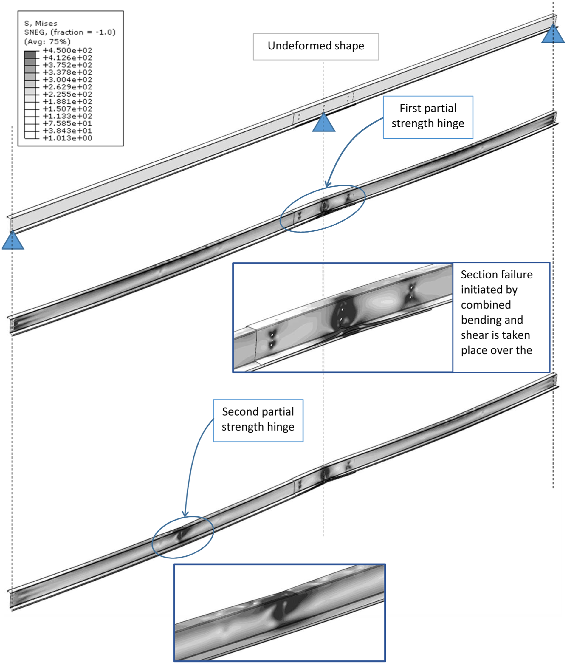
Model DSB-4D. In this model, as the moment resistance of the lapped Z-section has been significantly increased because of overlapping, the first ‘partial strength hinge’ cannot form at the lapped section over the internal support, as shown in Figure 11. Instead, the first ‘partial strength hinge’ is formed in the single Z-section close to one end of the lapped sections, that is, the critical single section, at which both the applied moment and shear force have only been reduced by a small extent, when compared with their maximum values at the internal support. As the applied load increases, moment redistribution takes place sharply within the beam due to highly non-ductile deformation characteristics of the Z-sections after section failure with a small residual moment resistance at large rotations. An additional ‘partial strength hinge’ is then formed near the mid-span of any one span of the beam, leading to an unsymmetrical system failure.
Models DSB-6D and DSB-8D. Due to the presence of long overlapping lengths, the failure mechanism of models DSB-6D and DSB-8D is very different from that of model DSB-4D. As the single sections of the lapped beam models are far away from the internal supports, both the applied moment and shear forces at the ends of the overlapped zones have been substantially reduced. Hence, the first ‘partial strength hinges’ will not take place at the critical single sections, and instead, they form in the lapped sections directly over the internal supports, as shown in Figures 12 and 13. As the applied loads increase, moment redistribution takes place gradually within the beams, and an additional ‘partial strength hinge’ is then formed near the mid-span of any one span of the beams, leading also to an unsymmetrical system failure.
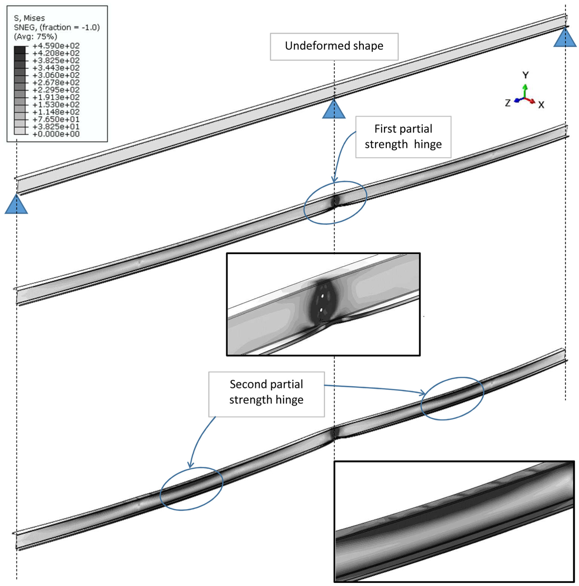
Deformed shape of model DSB.
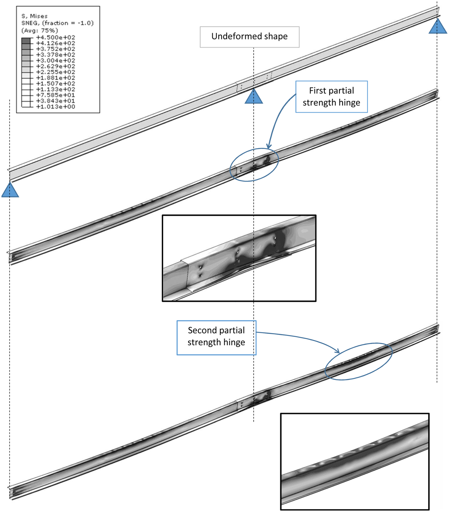
Deformed shape of model DSB-4D.
Deformed shape of model DSB-6D.
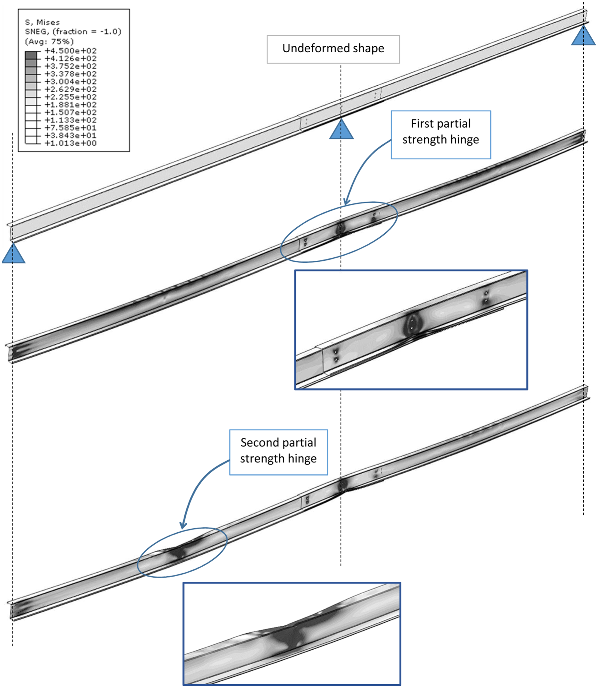
Deformed shape of model DSB-8D.
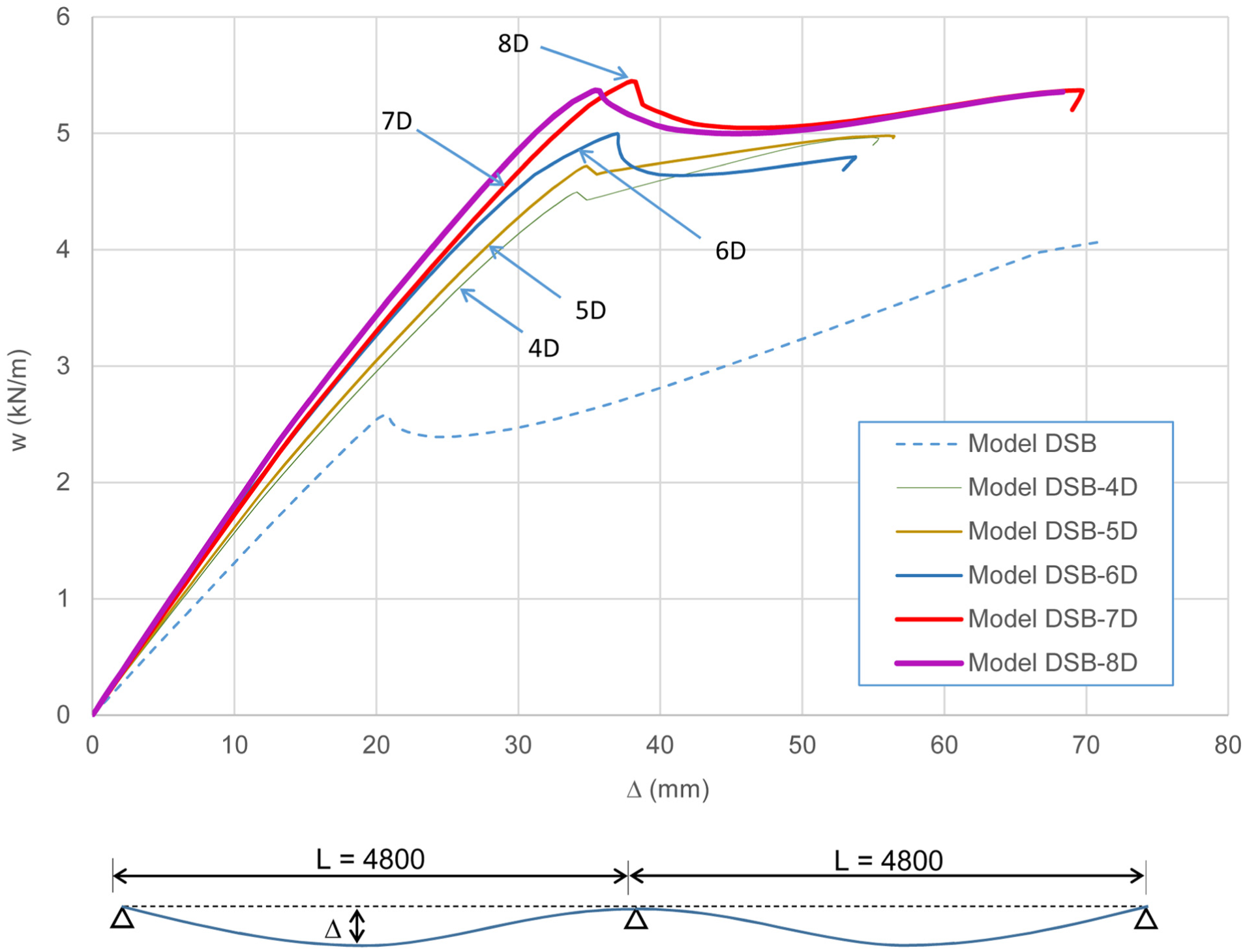
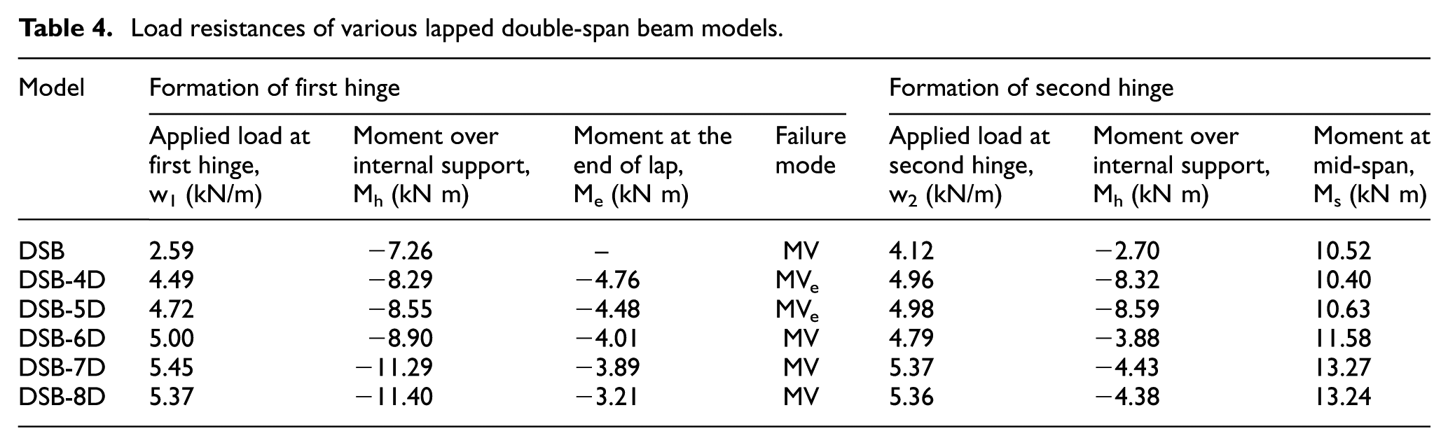
Figure 14 plots the load deflection curves of all the six models onto the same graph for direct comparison, while Table 4 summarizes the applied loads corresponding to various stages of deformations in both the continuous and the lapped beam models.
Load deflection curves of various models of double-span beams.
Load resistances of various lapped double-span beam models.
It should be noted that
In model DSB, the first ‘partial strength hinge’ is formed when the applied load, w, reaches 2.59 kN/m. After significant moment redistribution, the second ‘partial strength hinge’ is formed when the applied load, w, reaches 4.12 kN/m. It should be noted that there is a significant increase in the beam deflection associated with the formation of the second ‘partial strength hinge’ because of a significant reduction in both the residual moment resistance and the flexural rigidity of the Z-section directly over the internal support.
In all the lapped beam models, the first ‘partial strength hinges’ are formed when the applied load, w, reaches a value ranging from 4.49 to 5.45 kN/m. These are well above that of model DSB at 2.59 kN/m. Moreover, all the lapped beam models allow significant moment redistribution during formation of the second ‘partial strength hinges’, and the corresponding applied load, w, ranges from 4.79 to 5.37 kN/m.
In general, for all lapped beam models considered in this section, they behave superior to the continuous beam model in terms of both load resistances and deformations, as demonstrated in the load deflection curves. Moreover, model DSB-7D is shown to be the most effective among all the six models in terms of resistance, deformation and use of steel materials.
Conclusion
In this article, a systematic numerical investigation with advanced finite element modelling technique into the structural behaviour of cold-formed steel lapped Z-sections with different overlapping lengths is presented. Advanced finite element models with material and geometrical non-linearity are established to simulate the deformation characteristics of a total of six lapped Z-sections with different overlapping lengths. After incorporating carefully the interconnections provided at regular intervals along the spans of the Z-sections, the models have been successfully calibrated against test data. It is demonstrated that the predicted moment rotation curves of these models follow closely the measured data not only up to the maximum applied moment but also at large deformations.
In order to examine the structural performance of multi-span cold-formed steel purlin systems under gravity loads, these advanced models have been extended into lapped double-span beams with five different overlapping lengths directly over internal supports. Lateral restraints are provided to the Z-sections according to common practice, while typical magnitudes of these restraints are adopted in this study.
It is shown that
Advanced finite element models have been established to simulate successfully the structural behaviour of lapped Z-sections under single-point loads, and they are demonstrated to be effective in simulating full-range deformation characteristics of lapped Z-sections under combined bending and shear, including the highly non-ductile deformation characteristics after section failure.
Moreover, lapped double-span beams with practical overlapping lengths tend to behave superior to continuous double-span beams in terms of both load resistances and deformations. Depending on the overlapping lengths of the lapped sections, the first ‘partial strength hinge’ may occur at the single sections near the ends of the overlapping zones or at the lapped sections directly over the internal supports. After significant moment redistribution, the second ‘partial strength hinge’ is formed near the mid-span of any span of the beam, forming an unsymmetrical system mechanism.
Various restraints have been carefully incorporated into the finite element models according to common practice in modern roof structures, while the magnitudes of these restraints depend on specific connection details adopted. These restraints are very important as they affect the structural behaviour of the models significantly. While typical values adopted in this study are presented in section ‘Finite element modelling’, measured data of these restraints should be obtained directly in tests, wherever possible.
‘Radial’ spring elements are provided onto contact surfaces within the overlapping zones of the lapped Z-sections as their use often render a robust model which achieves numerical convergence readily, when compared with modern surface elements which may cause numerical instability at large deformations.
Due to the complexity of the problems, this investigation is by no means exhaustive. Other key parameters with significant effects on the structural behaviour of lapped Z-sections in double- or multi-span beams, such as the ratio of the overlapping length to the beam span, are not included. Hence, similar to many other finite element studies, key findings of the finite element models are problem specific, and they should only be generalized with cautions. Nevertheless, it is demonstrated that the proposed finite element models are able to provide accurate prediction to the structural behaviour of double-span or multi-span lapped Z-sections.
It should be noted that this study is part of an extensive experimental and numerical investigation into the structural behaviour of multi-span purlin systems using high-strength cold-formed steel Z-sections with overlaps. The proposed models will be extended to investigate the structural behaviour of high-strength cold-formed steel lapped Z-sections under a wide range of beam spans, and practical boundary and loading conditions will be reported in a separate article.
Footnotes
Declaration of Conflicting Interests
The author(s) declared no potential conflicts of interest with respect to the research, authorship and/or publication of this article.
Funding
The author(s) disclosed receipt of the following financial support for the research, authorship and/or publication of this article: The research project leading to the publication of this article is supported by the Research Grants Council of the Government of the Hong Kong Special Administrative Region (project no. PolyU5149/10E).