
Abstract
The objective of this study is to provide the engineering practice with a tool for simplified dynamic response assessment of high-speed railway bridges in the pre-design phase. To serve this purpose, a non-dimensional representation of the characteristic parameters of the train–bridge interaction problem is described and extended based on a beam bridge model subjected to the static axle loads of the crossing high-speed train. The non-dimensional parameter representation is used to discuss several code-related design issues. It is revealed that in an admitted parameter domain, a code-regulated static assessment of high-speed railway bridges may under-predict the actual dynamic response. Furthermore, the minimum mass of a bridge as a function of the characteristic parameters is presented to comply with the maximum bridge acceleration specified in standards.
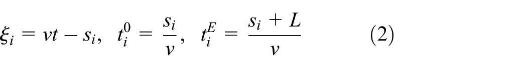
Keywords
Introduction
In general, structural design and assessment of railway bridges crossed by trains with moderate speed are based on outcomes of static analyses amplified by a dynamic load factor. Trains traveling with high speed, however, may excite railway bridges to resonance. Excitation to resonance at critical speeds is the result of repetitive loading of the crossed bridge, transferred through the train wheels to the structure. At a critical speed, the frequency of the repetitive axle loads is close to a natural bridge frequency or a multiple of it (Ju and Lin, 2003). Other sources of resonance are rail irregularities and wheel hunting oscillations (Xia et al., 2006). In a state of resonance, the bridge response can only be predicted by realistically conducting dynamic analysis. The phenomenon of resonance of railway bridges is described in detail, for instance, in the works by Ju and Lin (2003), Yang et al. (2004), and Xia et al. (2006, 2014). In some situations, however, the free vibrations induced by moving loads are canceled. An elaborate discussion on vibration cancelation and resonance disappearance is provided by Xia et al. (2014).
Several standards, design guidelines, and technical notes, such as EN 1991-2 (2003), ÖBB Infrastruktur (2011), and UIC 776-2 (2009), regulate whether the structural railway bridge assessment may be based on a simplified static analysis or a more elaborate dynamic computation must be conducted. A flow chart included in EN 1991-2 (2003) supports the engineer in this decision. The involved decision variables are the maximum line speed
For many bridges, dynamic computations can be avoided if the maximum line speed is less than or equal to
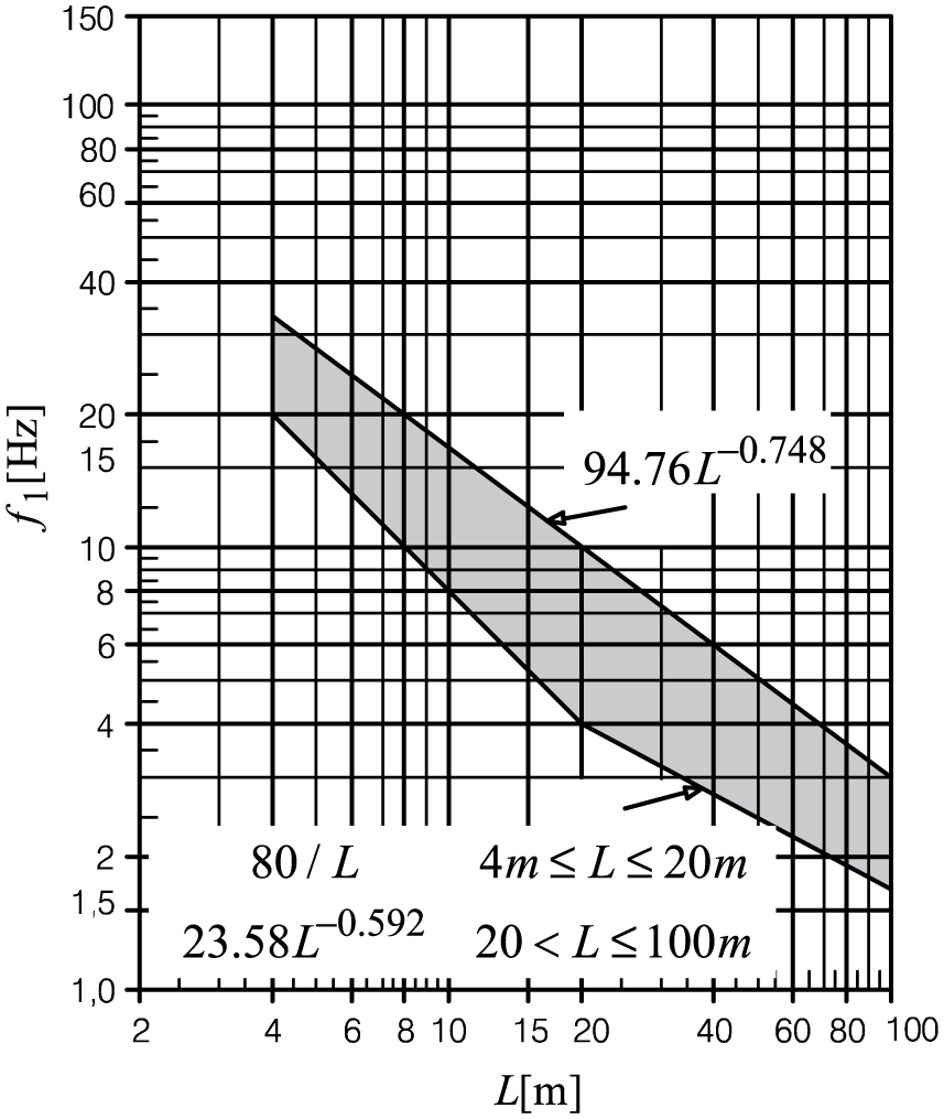
Domain (gray shaded) where no dynamic analysis is required as a function of the bridge fundamental frequency
In the design phase, vertical and horizontal deformation and twist of the bridge deck, internal forces, and in particular the vertical bridge deck acceleration must be assessed. The peak acceleration of the bridge deck is limited to satisfy the traffic safety of the train. For instance, at a certain bridge acceleration, the ballast becomes unstable, and consequently, the track quality is impaired. As outlined in several studies, such as Gulvanessian et al. (2009) and Ülker-Kaustell and Karoumi (2012), the bridge acceleration response is often the limiting and decisive quantity when a dynamic assessment is necessary.
For dynamic analysis of the complex train–bridge interaction system, models of various degrees of sophistication can be employed. Different modeling strategies and simplifications have, however, a significant effect on the accuracy of the response prediction. In a model close to reality, the bridge is discretized by means of three-dimensional finite elements, and a multi-body system composed of rigid masses connected through spring-damper elements is utilized for the train vehicles (see, for example, Gonzalez and Karoumi, 2014; Liu et al., 2009). Several interaction models have been developed to couple the train and the bridge subsystem, as outlined, for instance, in the work by Salcher (2015). Complex numerical modeling is time consuming and it requires special trained and experienced engineers. Furthermore, the mechanical properties of the crossing trains are often not disclosed by the manufacturer and for trains developed in the future naturally not available at present. However, the verification of a preliminary bridge design must be both time-efficient and cost-effective, and thus, elaborate modeling is usually not feasible.
Consequently, many less elaborated modeling strategies have been proposed and employed in engineering practice. Simplifications apply to both the train and the bridge subsystem. For these models, the number of parameters is assessable, and these parameters are readily available. Additionally, results are obtained in a timely manner. In the simplest approach, the effect of the train on the bridge is described by a series of concentrated forces (representing the static axle loads) crossing the bridge model with constant speed. This approach neglects the beneficial effect of bridge–vehicle interaction on the dynamic bridge response in the critical state of resonance (Museros et al., 2002; Yang et al., 2004). Dynamic analyses according to EN 1991-2 (2003) are based on high-speed load model sets referred to as HSLM-A and HSLM-B, which comprise several single force load models with different spacing and load amplitude, and additionally on single force load models representing real operating trains.
The one-dimensional beam is the simplest and oldest approach to model the entire bridge composed of load bearing system, ballast, and track. It is still extensively used in the research community (see, for instance, Frýba, 2001; Xia et al., 2006; Yang et al., 2004). Salcher (2015) has shown that a beam model captures the global dynamic deflection, and, with some limitations, the overall acceleration response behavior of slender beam-like bridges. These simplified models are, however, also useful for preliminary studies on more complex bridges.
This article provides a description of the Euler–Bernoulli beam bridge model by means of characteristic variables in the non-dimensional parameter space as introduced previously by Yang et al. (2004) and Adam and Salcher (2014). This non-dimensional representation allows the derivation of so-called response spectra, which (when readily available) can be used to assess the dynamic peak response of a high-speed railway bridge in the pre-design phase without costly response history analysis. These spectra reveal global interdependencies between the parameters of the problem. The spectra presented subsequently are based on simply supported beam bridges because this type of structure is in particular prone to vibrations. However, the concept can be used for any type of beam bridge. Additionally, it is discussed how code-based regulations concerning the range of application of static and dynamic methods of analysis can be globally assessed. In a further application, it is shown how the minimum mass of a bridge required for non-exceedance of the maximum admissible bridge deck acceleration can be estimated. The focus of this article is on provisions regulated in EN 1991-2 (2003). For more details, refer to Salcher (2015). First, the underlying equations of the considered beam bridge problem are briefly recapitulated.
Beam bridge model
In this study, the considered simply supported single-span bridges are modeled as linear elastic Euler–Bernoulli beam of constant mass per unit length
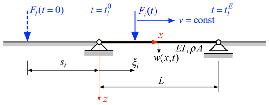
Lateral single force crossing a simply supported beam bridge with constant speed v.
Dirac delta function
The solution of equation (1) is found by modal decomposition of deflection w into the mode shapes
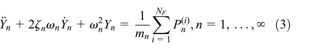
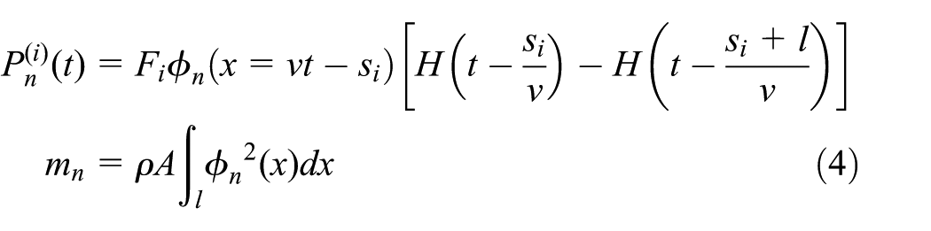
In application, the modal series is approximated by a finite number of modes.
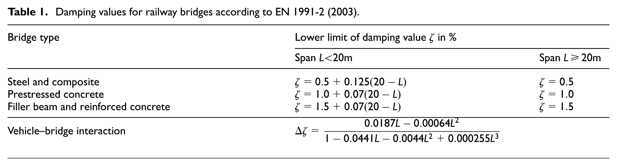
Damping values for railway bridges according to EN 1991-2 (2003).
Characteristic non-dimensional variables of the train–bridge system
It is desirable to rewrite the dimensional variables and parameters in terms of a set of non-dimensional characteristic parameters, whose number is in general smaller than the number of the original variables. A non-dimensional parameter representation provides a global overview of the behavior of the problem and reveals the interdependencies between certain variables. A well-known scheme for non-dimensionalization is the Buckingham
The considered vehicle–bridge interaction problem simplified as an Euler–Bernoulli beam crossed by the static axle loads with speed v is entirely described by the following non-dimensional quantities (Adam and Salcher, 2014):
An excitation parameter, that is, the speed parameter;
Non-dimensional response parameters for kinematic response quantities and internal forces;
A geometric parameter;
The damping coefficient.
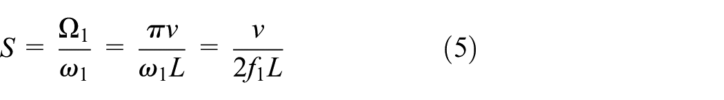
The speed parameter S is defined as the ratio of the fundamental excitation circular frequency
An appropriate non-dimensional characteristic representation of the deflection w, bending moment
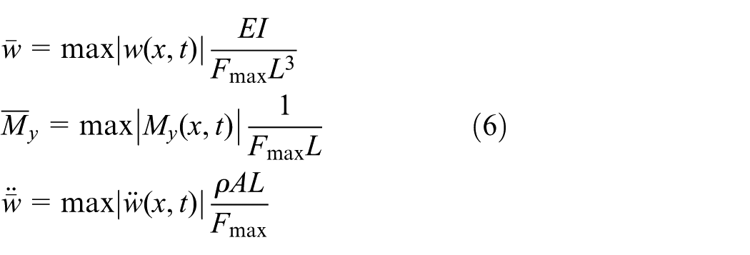
initially proposed by Hauser and Adam (2007) and Salcher (2010).
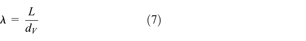
For articulated and conventional trains, the effective axle spacing
These characteristic parameters allow a global representation of the train-induced bridge response by means of a so-called response spectrum as subsequently discussed.
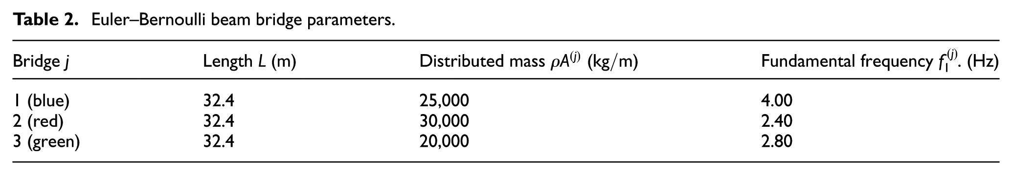
As an example problem, three simply supported bridges (differentiated by superscript
Euler–Bernoulli beam bridge parameters.
The beam bridges are crossed by the so-called HSLM-A10 load model. The HSLM-A10 is one out of ten load models of the HSLM-A load set specified in EN 1991-2 (2003), referred to as HSLM-A1, HSLM-A2,…, HSLM-A10. These load models differ in effective axle spacing, number of axles, and axle load, and they are supposed to represent current and future high-speed trains. The HSLM-A10 load model depicted in Figure 3 has
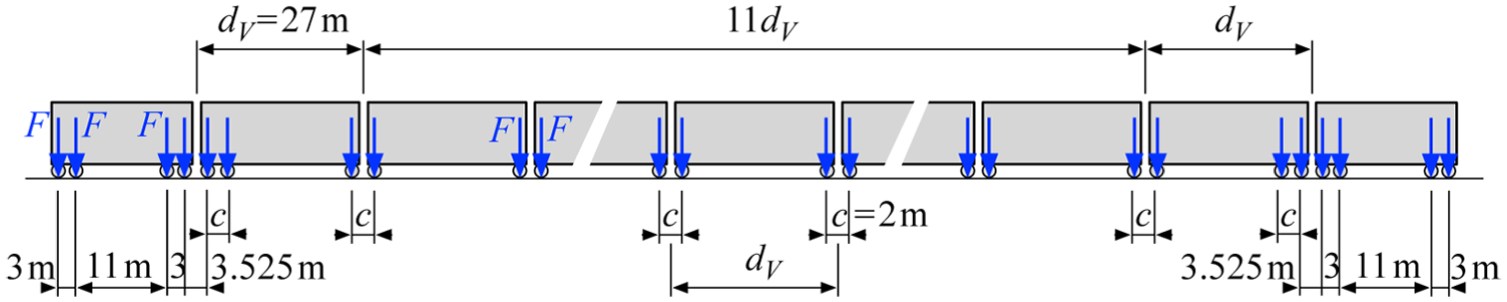
Load model HSLM-A10 specified in EN 1991-2 (2003).
The bridge acceleration
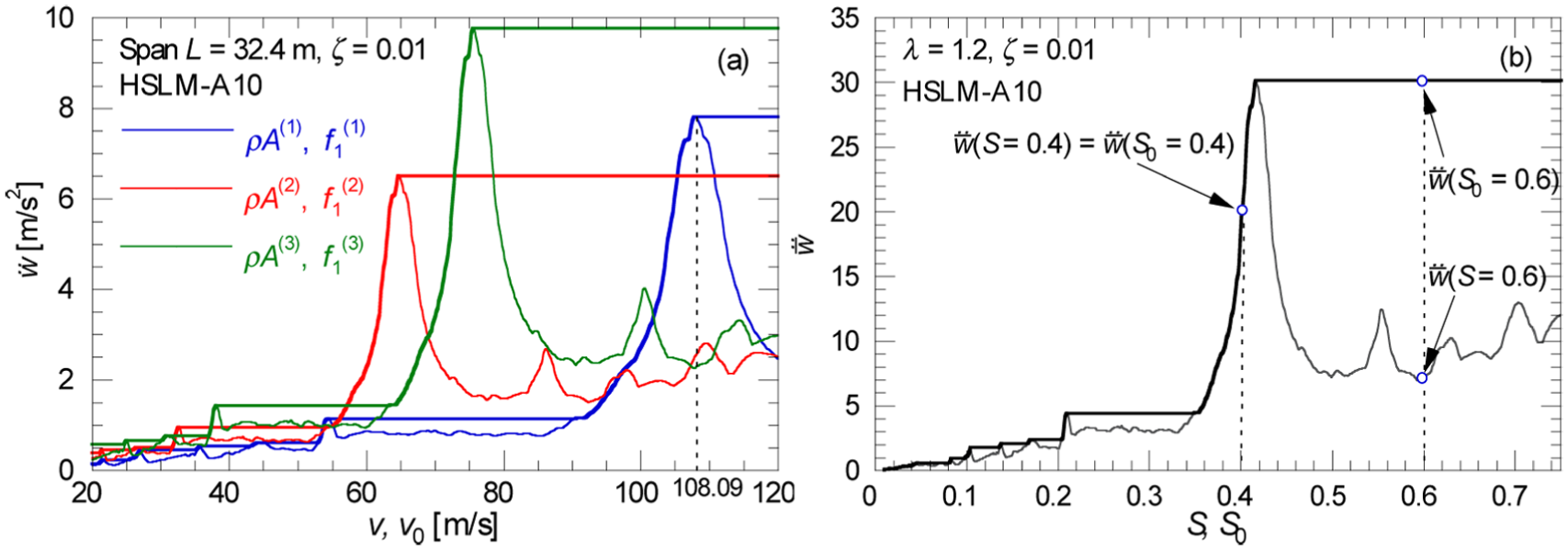
(a) Acceleration response of three different simply supported beam bridges of same span length and damping subjected to the HSLM-A10 load model and (b) corresponding non-dimensional representation.
Translating speed v and peak acceleration
When speed parameter S slightly exceeds a resonance speed, the peak response decreases, as it is observed in Figure 4. For bridge design, however, only the global peak response in the considered speed range
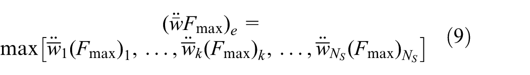
Expressed by means of characteristic non-dimensional parameters, the maximum peak response of a design spectrum in the range
This non-dimensional response representation facilitates various applications as subsequently discussed.
Design chart
Plotting the non-dimensional peak acceleration
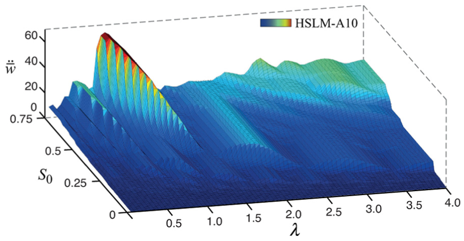
Non-dimensional peak bridge acceleration
For application in engineering practice, a two-dimensional representation of the peak response as a function of geometric ratio
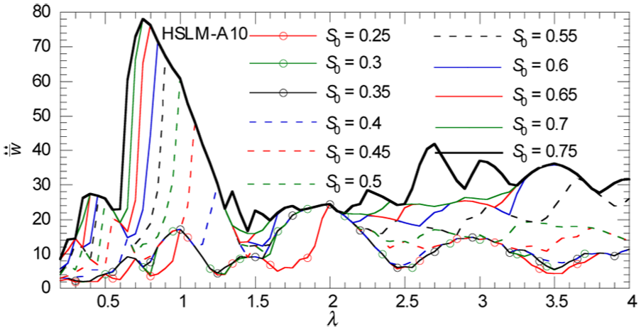
Design chart for simply supported steel and composite beam bridges subjected to the HSLM-A10 train model.
Design charts may be generated not only for a single train model but for an entire train set, such as for the HSLM-A load set of EN 1991-2 (2003). However, design charts for a train set cannot be represented completely non-dimensionally anymore. Since axle spacing (i.e.
is then plotted against the actual span L.
As an example, Figure 7 shows the corresponding design chart
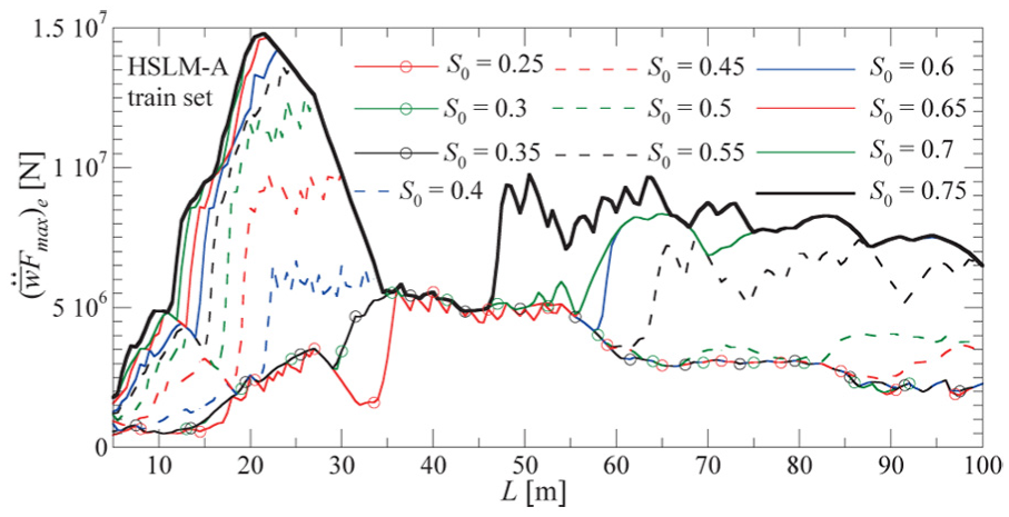
Design chart for simply supported steel and composite beam bridges subjected to the HSLM-A train set.
Providing that such a design chart is readily available, the maximum peak response of the bridge crossed by the considered train set can be identified without response history analysis. However, the information of the location of the peak response and of the particular train, which induces the peak response, is not available.
Evaluation of code-regulated static analysis approach
The non-dimensional representation of response and excitation parameters allows the comparison of the outcomes of different design proposals in the full parameter space.
According to EN 1991-2 (2003), for many simply supported bridges crossed by trains with operating speed
Load model LM71 for a static assessment according to EN 1991-2 (2003).
As an example, the yellow shaded plane depicted in Figure 9 represents the maximum static deflection of simply supported beam bridges, subjected to the LM71 load model amplified by the dynamic factor
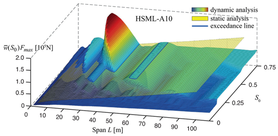
Peak deflection parameter
Dynamic analyses have been conducted for the 10 load models of the HSLM-A train set. Projecting for each load model, the lines of intersection in the
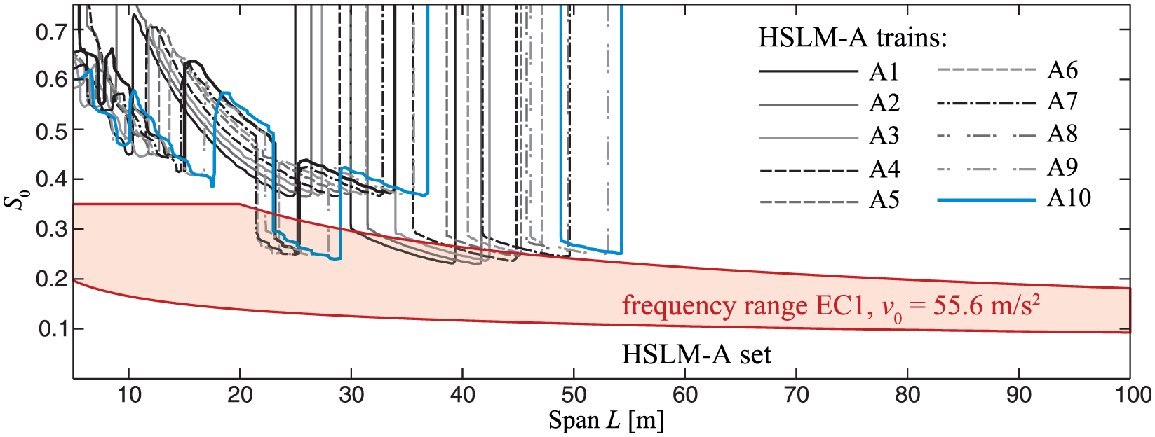
Domains where the dynamic peak deflection of simply supported steel and composite beam bridges exceeds the corresponding static response prediction. Load models A1–A10 of the HSLM-A train set (EN 1991-2, 2003). Red shaded area: static analysis admitted according to EN 1991-2 (2003).
It is observed that the red shaded area and the areas limited by the intersection lines overlap in certain domains. That is, in these overlapping domains, a static (EN 1991-2, 2003) analysis under-predicts the actual dynamic response and thus is unsafe although admitted according to EN 1991-2 (2003). Only for spans
From the results of this study, it can be concluded that the lower frequency limit confining the domain according to EN 1991-2 (2003) (which corresponds to the upper limit of the boundaries expressed in
Minimum mass needed for passing code acceleration limits
In codes and standards, the vertical bridge acceleration is limited to guarantee the traffic safety. The ballast of ballasted tracks becomes unstable if the bridge deck acceleration exceeds a certain value, and thus, the safety of the train passage is not ensured anymore. EN 1991-2 (2003) specifies for bridges with ballasted tracks an acceleration threshold of
Subsequently, a quick pre-design check is implemented to verify whether the mass of the bridge is sufficiently large to satisfy the bridge acceleration limits specified in codes and standards.
Substituting, for instance, the lower acceleration threshold of
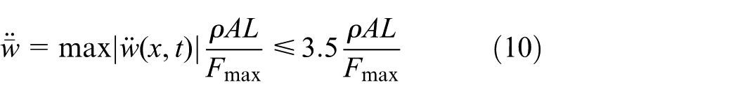
This expression is solved for the mass per unit length, leading to the minimum distributed mass
The derivation of response quantity
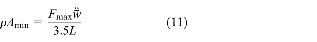
As an example, Figure 11 shows for steel and composite beam bridges subjected to the HSLM-A load set the minimum mass
Minimum mass per unit length of simply supported steel and composite beam bridges subjected to the HSLM-A train set for non-exceedance of the acceleration limit of
Note that in speed parameter
Additionally, the red shaded area in Figure 11 represents the domain, where a static assessment according to EN 1991-2 (2003) is admitted, compare also with Figure 10.
As an application example, a simply supported steel bridge with span
Summary and conclusion
It has been shown that a non-dimensional representation of excitation, response, and geometric variables of the high-speed train–bridge interaction problem allows the derivation of design spectra and design charts in the full parameter space, which can be used for a quick assessment of the peak response in the pre-design phase of a bridge.
These spectra have been used to evaluate a regulation of EN 1991-2 (2003) concerning the assessment of bridges by means of static and dynamic methods of analysis. From this evaluation, it can be concluded that this regulation should be modified because for certain admitted parameter combinations, the outcome of a static analysis under-predicts the actual dynamic response.
In an additional application, it has been shown how the required minimum mass of a bridge can be estimated to avoid an exceedance of code-regulated bridge acceleration thresholds in the pre-design phase.
Footnotes
Declaration of Conflicting Interests
The author(s) declared no potential conflicts of interest with respect to the research, authorship, and/or publication of this article.
Funding
The author(s) received no financial support for the research, authorship, and/or publication of this article.