






Abstract
The behaviour of bridge columns strengthened using carbon fibre–reinforced polymer composites has been studied extensively. However, few investigations have been conducted regarding the influence of carbon fibre–reinforced polymer-strengthened columns on the seismic behaviour of reinforced concrete continuous girder bridges. This article details the hybrid simulations of a continuous reinforced concrete girder bridge whose columns are strengthened by carbon fibre–reinforced polymer jackets. In the hybrid simulations, one ductile column is selected as the experimental element, which is represented by a 1/2.5-scale specimen, and the remaining bridge parts are simultaneously modelled in OpenSees (the Open System for Earthquake Engineering Simulation). After combining the experimental element and the numerical substructure, the hybrid analysis model is developed with the established hybrid simulation system. The displacements of the bridge and the lateral force–displacement response of the experimental element in hybrid simulation are obtained. Compared with the results of numerical simulation, the stability and accuracy of the established hybrid simulation system are demonstrated. Meanwhile, the comparative hybrid simulation results of the as-built bridge and the carbon fibre–reinforced polymer-strengthened bridge also prove the effectiveness of the carbon fibre–reinforced polymer jackets’ confinement in the continuous reinforced concrete girder bridge.
Keywords
Introduction
The study of repairing, strengthening and retrofitting existing bridges has become of great significance in recent decades due to design code updates and structural materials’ ageing. Carbon fibre–reinforced polymer (CFRP) composites are widely used in the retrofitting and strengthening of reinforced concrete (RC) bridges because of several superior properties, including their light weight, high strength, high modulus of elasticity and corrosion resistance.
Various columns with CFRP composite retrofits have been tested to obtain their cyclic performance. The factors that influence the performance of CFRP-strengthened RC columns have also been experimentally investigated, such as section sizes, aspect ratio, volumetric ratio of lateral steel, the level of axial load, fibre-reinforced polymer (FRP) jacket confinement stiffness and the area of FRP confining reinforcement (Delgado et al., 2012; Gu et al., 2010; Haroun and Elsanadedy, 2005; Iacobucci et al., 2003; Seible et al., 1997; Sheikh and Bayrak, 2001). In these aforementioned quasi-static tests, the column specimens were subjected to a predefined history of loads or displacements at a lower rate, and as a result, the cyclic responses of the columns are unable to accurately reflect the effectiveness of CFRP composite during an actual seismic event. Given this, the scaled RC bridge column specimens repaired with CFRP composite were tested on a shaking table to verify the effectiveness of CFRP composite jackets for damaged RC bridge columns subjected to a series of ground motions (Kumar et al., 2014). However, due to the limited capacity and size of the shaking table, only small reduced-scale specimens were suitable for the shaking table tests, and the test configuration was restricted by the dynamic similitude law. Such harsh terms made it easy for the shaking table tests to become complicated and expensive. Another alternative approach for acquiring seismic responses of the CFRP-repaired RC bridge columns is pseudo-dynamic testing. Chang et al. (2004) performed pseudo-dynamic testing of as-built and CFRP-repaired RC bridge columns that were simplified as a single-degree-of-freedom (SDOF) system with a lumped mass. In the experiments, as discussed above, only bridge columns were physically tested. Although the retrofit effectiveness using CFRP composite to strengthen the RC columns has been verified, studies regarding such efficiency in the entire bridge are rare.
The aim of this study is to determine the response of a continuous RC girder bridge whose columns are strengthened by CFRP jackets under earthquake loading in the longitudinal direction. For this purpose, hybrid simulation (HS), as the state-of-the-art structural experimental method, is used in this article. HS, which is derived from the pseudo-dynamic testing method, is formerly called the substructure pseudo-dynamic testing method. In HS, using substructure test technology, the target structure is generally divided into several subassemblies on the basis of its characteristics or the research focus, which are simply grouped into two categories: numerical and experimental substructures. The numerical substructure comprises the parts that are appropriate to simulate via finite element analysis software, while the experimental substructure refers to the parts that need to be tested in the laboratory because their behaviour is too complex to be analysed precisely by numerical simulation (NS). Through reasonable boundary condition coupling and coordination, a hybrid analysis model of the overall structure is developed so that the seismic response of the structure can be obtained by solving the equations of motion for the hybrid analysis model (Elkhoraibi and Mosalam, 2007; Schellenberg et al., 2009; Yang et al., 2009). Some peers have conducted studies to apply HS in bridge structural experiments (Mosqueda et al., 2006; Pinto et al., 2004). For instance, Terzic and Stojadinovic (2013) conducted HS tests on a typical overpass bridge in California to study the traffic performance after a major earthquake event. They developed a three-dimensional hybrid analytical model that consisted of a scaled column specimen representing the bottom half of an end bridge column.
This article focuses on how to use HS to estimate the influence of CFRP-strengthened columns on the structural response of an overall bridge when subjected to dynamic loading caused by an actual seismic event. In these HSs, one of the ductile columns (Column 3) below the fixed bearing is regarded as the experimental element that is represented by a scaled column specimen for the hybrid analysis model. Meanwhile, the remaining portion (i.e. box girders, bearings, cap beams and other columns) is treated as the numerical substructure and modelled in OpenSees (the Open System for Earthquake Engineering Simulation). To conduct the HSs, a hybrid simulation system (HSS) is developed to integrate and couple the numerical substructure and the experimental element. The developed HSS is validated utilizing OpenSees NS. It is also experimentally confirmed that seismic reinforcement of the continuous RC girder bridge by wrapping FRP jackets in the plastic hinge region of bridge columns is effective.
Prototype structure and the hybrid analysis model
Prototype structure and strengthening procedure
In the HSs, the prototype bridge used as the reference target structure is a four-span RC highway bridge. From axis to axis, each span is 20 m, and the main RC box-girder is 80 m long. Transverse cap beams of 6 m are located at the upper two columns. Each column has a 1-m-in-diameter circular cross-section and a total length of 4 m. The central bearing support is fixed, while the others are sliding ones. The prototype continuous girder bridge is presented in Figure 1.

Prototype as-built continuous RC girder bridge and the strengthening scheme: (a) longitudinal elevation, (b) transverse elevation, (c) column section and (d) strengthening scheme of columns.
In general, the ‘top-heavy’ feature of bridge structure leads to inertial force caused by ground motion clustering in the superstructure of the bridge, causing the bridge columns to resist the lateral forces. Hence, according to the ductile design rules, the possible plastic hinges, which are expected to occur due to a strong earthquake, are selected in the bridge columns in the bridge design. This designs the RC columns as ductile members; to improve the bridge deformation performance, it is necessary to strengthen and retrofit all bridge columns.
As the first phase of the study, the investigation of the seismic performance of the overall bridge in the longitudinal direction will be conducted. When an earthquake takes place along the longitudinal direction of the continuous RC bridge, the potential plastic hinges are usually found at the bottoms of the columns. A strengthening scheme is determined such that all columns are wrapped with CFRP jackets in the possible plastic hinge zone to provide confinement of the core and prevent the concrete cover from spalling (Pantelides et al., 1999).
Figure 1(d) depicts the strengthening scheme with CFRP jackets in the plastic hinge region of the columns. The constraint regions in each column consist of primary and secondary areas. Both the primary and secondary strengthening areas have the same length of 500 mm, which is one-eighth of the column height. Each column is wrapped with four layers of CFRP composite in the primary zone and two layers of CFRP composite in the secondary zone (Seible et al., 1997). A gap of 20 mm between the column base and the lower edge of the CFRP-strengthened region is reserved to prevent the CFRP composite from being directly affected by the vertical pressure (Xiao et al., 1999). The properties of the steel rebars, concrete and CFRP composite in the bridge are summarized in Table 1.
Properties of the steel bar, concrete and CFRP.
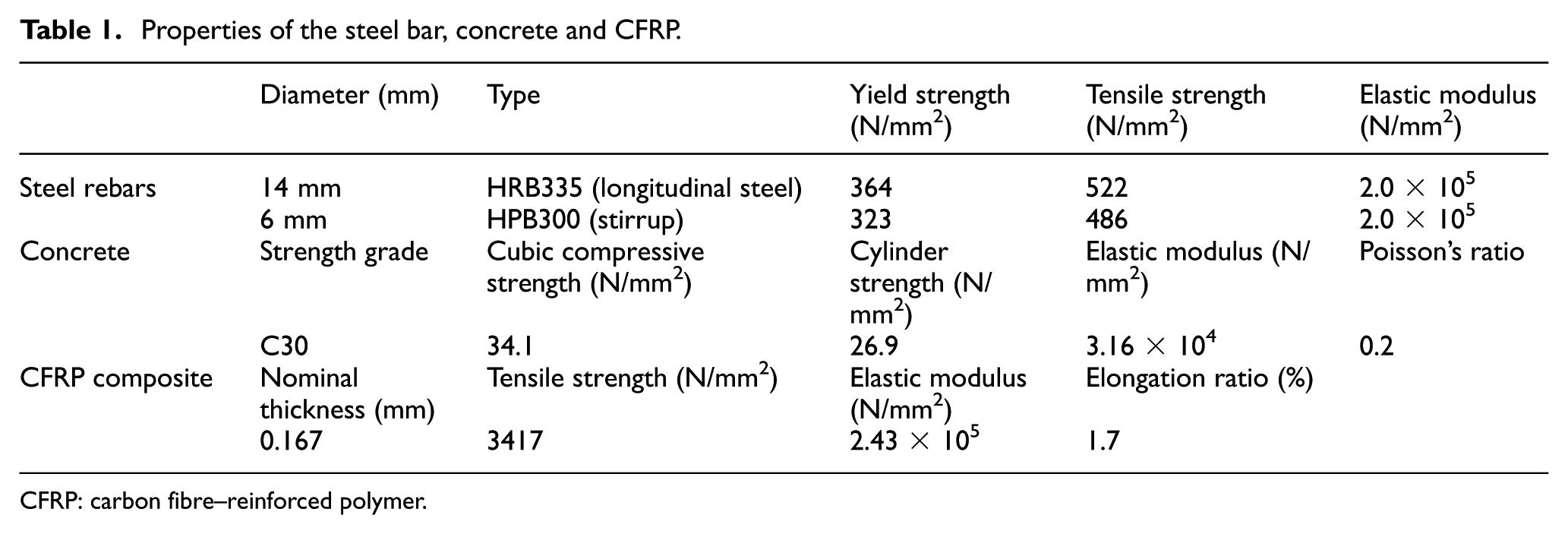
CFRP: carbon fibre–reinforced polymer.
Hybrid analysis model
It is ideal to build a full-scale prototype of the bridge to evaluate the local and global behaviour of the bridge. However, the size of the target bridge makes the construction unrealistic. In HS, researchers are able to split a large target structure into subassemblies via a substructure testing technique and then develop a hybrid analysis model, rather than developing an overall finite element model or building the entire structural specimen in the laboratory. These subassemblies are simulated by two approaches: numerical analysis and experimental testing. Thus, as far as the implementation of the HS for the performance estimation of structures is concerned, it is critical to distinguish the experimental portion from the other subassemblies prior to developing the hybrid analysis model of the bridge.
Numerical substructures refer to the components for which the behaviour is elastic or well known; these parts can be modelled by finite element analysis software. The experimental substructures are the portion where the behaviours are highly nonlinear or complicated such that their NS results are not very accurate; hence, researchers are compelled to tests the experimental elements physically in the laboratory. In addition, researchers also could select the critical components of the target structure as the experimental elements if interested.
The as-built bridge is designed for ductile behaviour, and the columns are designed as the ductile component. The remaining portion, such as box girders, bearings and cap beams, is designed as capacity-protected members. In the capacity design principles of bridges, through introduction of the safety-level difference between capacity-protected members and the ductility component, the nonlinear behaviour of the bridge can be ensured to appear at the plastic hinge of the ductile member by seismic excitation (Akiyama et al., 2012). Due to the protection of the ductile columns, capacity-protected members, that is, box girders, bearings and cap beams, remain elastic under earthquakes. In accordance with the principle of experimental element selection for the hybrid analysis model, the bridge columns are the best choice for the experimental substructure. Moreover, the inertial forces of the superstructures are mainly resisted by the columns below the fix bearing. The other columns, which are located below floating bearings, mainly suffer horizontal friction. Therefore, Column 3 and Column 4 below the fixed bearing play a key role in the seismic performance of the bridge. Considering the limitations on the capability of the testing facility, only Column 3 is tested physically; Column 4 and the other components are modelled in OpenSees simultaneously; after coupling the boundary condition of the experimental element with the numerical substructure, the hybrid analysis model of the entire bridge is developed, as shown in Figure 2.

Hybrid analysis model of the continuous girder bridge.
Experimental elements
As described above, Column 3 is considered as the experimental element in the hybrid analysis model of the entire bridge, which is represented by a column specimen. Some deformation equalization of the experimental element is needed before preparing the column specimen. The bending deformation of Column 3 under the longitudinal earthquake is presented in Figure 3(a). A cantilever column is used to simplify Column 3 with consideration of the displacement compatibility in the longitudinal direction of the bridge.

The details of the experimental element (Column 3): (a) the bending deformation under the longitudinal earthquake, (b) schematic of the strengthening scheme, (c) photo of the as-built column specimen and (d) photo of the CFRP-strengthened column specimen.
Two test specimens are prepared for the comparative HSs regarding the CFRP strengthening effect: one is the original column and the other is a column strengthened by CFRP jackets. Both specimens are made of the same material as the prototype. In Figure 3, two 1/2.5-scale test specimens are designed; the total height of the column specimen is 1800 mm, which includes a 400-mm-tall column cap. The cross-section and the CFRP length are determined by the length scale.
To satisfy the degrees of freedom of the experimental element (one lateral displacement), one servo hydraulic actuator is employed to impose the horizontal displacements at the column cap of the specimens. Because the effect of axial load on the seismic performance of columns cannot be neglected (Mirmiran et al., 1998; Xiao and Zhang, 2006), one hydraulic jack with a spherical hinge provides the axial compression at the top of the specimen. Figure 4 shows the experimental test setup. To compare the command displacement with the actual displacement, two linear variable differential transformer (LVDT) position sensors are mounted at the top end and the bottom of the column specimen, respectively, and the lateral displacement of the column specimen can be calculated using the LVDT sensors value.

Schematic and photo of the experimental test setup: (a) schematic of the experimental setup and (b) photo of the test configuration.
Numerical substructure
Except for Column 3, the major part of the bridge is modelled in OpenSees. Hence, particular emphasis should be placed on the nonlinear analysis for the numerical subassemblies, which is directly related to the accuracy of the tests. As mentioned above, for the as-built bridge, the box girders, bearings and cap beams are designed as capacity-protected members and remain essentially elastic during designed earthquakes. These capacity-protected members also have some ductility in case of unexpected damage. Considering that the box girders have far greater stiffness than the other members, they are modelled as elastic elements. The flat slider bearing elements are utilized to model the floating bearings, whose force–deformation behaviour is defined by an elastic uniaxial material model. A multi-point constraint is constructed at the position of the fixed bearing using the equal DOF command in OpenSees to represent the fixed bearing. Displacement-based beam–column elements are adopted to describe the force–deformation behaviour of the cap beams and the numerical columns.
There are three types of concrete material models exploited in the numerical substructure, that is, CFRP-strengthened concrete, core concrete and cover concrete, as shown in Figure 5(a). The confinement effectiveness of the CFRP jackets is evaluated with the Lam and Teng (2003) model, and it is calculated that the compressive strength of the CFRP-strengthened concrete is increased by approximately 78% compared to the cover concrete. Note that the stress–strain model for CFRP-confined concrete used in this article does not include the descending stage. The concrete stress–strain relationship including the stirrup-confined effect is determined, which is assigned to the core concrete, based on the model proposed by Mander et al. (1988). The Kent–Park model is used as the compressive stress–strain relationship of the cover concrete (Kent and Park, 1971). Giuffrè–Menegotto–Pinto steel material model with isotropic strain hardening is selected to represent the uniaxial stress–strain relationship of the steel rebars (Menegotto and Pinto, 1973).

Details of the numerical substructures: (a) the stress–strain models of the concrete and (b) elements and sections of the numerical column.
The numerical column model is divided into 10 sub-elements using the fibre cross-sections, force-based beam–column element with distributed plasticity. The length of the sub-elements in the potential plastic hinge region is half that of the other part in the numerical columns. There are five integration points along each sub-element. Elements and sections of the numerical column are shown in Figure 5(b). The mass distribution is defined by the element mass density along the length. Rayleigh damping is used in OpenSees to apply structural damping (0.05) to the hybrid analysis model. The Newmark-β method with γ = 0.5 and β = 0.25 is adopted to solve the motion equations.
The HSs schedule
The different scaled versions of the ground motion record of the 1940 El Centro Earthquake are used as the seismic ground motions in the HSs. Depending on the Chinese criterion for seismic design of urban bridges, this bridge should stand up to the E1 and E2 earthquake actions under a seismic intensity of 7, and the corresponding peak ground accelerations (PGA) are 0.046 and 0.22 g. Both the as-built bridge and the CFRP-strengthened bridge are subjected to two earthquakes successively. Table 2 gives the schedules of HSs and the subsequent comparative NSs.
Hybrid simulations schedule.
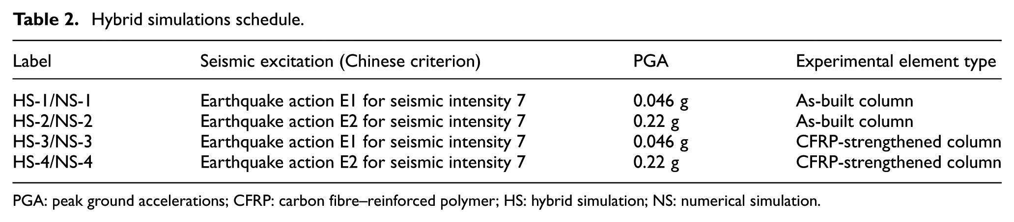
PGA: peak ground accelerations; CFRP: carbon fibre–reinforced polymer; HS: hybrid simulation; NS: numerical simulation.
HSS setup
System architecture for HS
For the implementation of HS, a HSS is developed. The component and the signal flow are illustrated in Figure 6. This HSS, based on the MTS servo hydraulic control system, consists of the finite element analysis framework OpenSees (PEER 2015), OpenFresco (the Open-source Framework for Experimental Setup and Control; Schellenberg and Mahin, 2006), the MTS 493 test control system and the data acquisition (DAQ) system.

System architecture for hybrid simulation.
The MTS 493 servo control system, which is always used in the quasi-static tests in the Jiangsu Key Laboratory of Structural Engineering (JKLSE), is composed of one actuator, a FlexTest GT Controller and the MTS 493 software (i.e. MTS station manager). The proportional–integral–derivative (PID) control scheme is utilized to control the actuator. When the hydraulic pump works at full capacity, the digitally controlled servo hydraulic actuator is capable of producing forces up to 1000 kN. OpenSees is an open-source object-oriented framework for finite element analysis. It has advanced capabilities for modelling and analysing the nonlinear responses of systems due to its various material models, elements models and solution algorithms (Open System for Earthquake Engineering Simulation (OpenSees), 2014). OpenFresco is an environment-independent software framework that connects finite element models with the control and DAQ systems in laboratories to facilitate HS of structural and geotechnical systems.
HS procedure
In this article, the HSs are executed on an extended time scale, that is, slow HS. Due to the expanded time scale, details of the destruction process can be captured to study the destruction mechanism behind the failure phenomenon. Moreover, the dynamic similitude requirements are reduced and the static similitude law is able to satisfy the similitude requirements in slow HS. If the fundamental dimension scale factors are determined, the other scale factors can be derived according to the similitude principles (Kumar et al., 1997). As the length scale factor (Sl) is 1/2.5, the force scale factor (SF = Sl2) is calculated to be 1/6.25 from the dimensional analysis. Displacement control strategy is adopted in HS. Both the displacement command and the force feedback of the test specimen should be multiplied by the coefficients associated with the scale factors, and this process is conducted by OpenFresco.
In each load step, the target displacement of the experimental element calculated by OpenSees has to be scaled down by the length scale ratio (0.4) as the command displacement of the specimen before being sent to the MTS servo control system. Then, the actuator applies the command displacement to the test specimen, and the feedback force is measured with the built-in force sensor of the actuator. Similarly, the force feedback also needs to be scaled up by the reciprocal of the force scale factor (1/SF = 6.25) to represent the restoring force of the experimental element in the hybrid analysis model. After inputting the restoring force of the experimental element into the governing motion equation, the seismic response of the entire bridge structure at the present step is solved, and at the same time, the displacement command for the subsequent step is calculated.
HS results
Failure phenomenon
There are almost no significant cracks on the surface of the as-built column specimen in HS-1 until the peak deformation reaches 4 mm. The fine cracks are mainly horizontal and distributed evenly on the tension side of the column. As the displacement decreases, the cracks gradually close.
The cracks of the as-built column specimen during HS-2 developed more severely than HS-1. As shown in Figure 7, in HS-2, the homogeneous cracks appear horizontally not only at the bottom of the column specimen but also at the column body. The maximum crack width was approximately 1 mm. When the peak displacement reaches 32.5 mm, there are some spalling concretes at the bottom of the column, and the plastic hinges occur in the specimen. In contrast, there is no damage at the surface of the CFRP-strengthened column specimen during HS-3 and HS-4. The surface of the CFRP-strengthened column specimen remains the same after HS-4.

Damage of the as-built column specimen.
In addition, the maximum strain of the cover concrete at the CFRP-strengthened column in HS-4 is 2421 µε, which is much larger than that of the as-built column in HS-2 (2116 µε). Therefore, the plastic performance of the protective layer concrete is improved due to the contribution of the CFRP constraint.
Experimental results analysis
Displacement analysis
In the target bridge, the box girders and Cap Beam 2 are fixed together with the fixed bearing, the rigid joints form at the connections between Cap Beam 2 and Column 3, and the lateral displacement of the box girders in the longitudinal direction equals that of the bridge’s Column 3. Thus, the deformation of the experimental element (Column 3) can be used to evaluate the seismic behaviour of the overall bridge. Figure 8 provides the lateral displacement histories of Column 3 during two sequential ground motions. To validate the HS models, each HS displacement result and the corresponding numerical analysis results are plotted in the same figure. The displacements obtained from HS and NS during each ground motion are approximately identical, and the phases of each curve are more or less similar. In comparison, the amplitude peak of the displacement from HS is larger than that of the NS, and the post-peak phases vary slightly. This good agreement illustrates the feasibility of using HS and the accuracy of the numerical substructure in OpenSees.

Comparison of the lateral displacement histories of Column 3 from HS and NS.
To evaluate the influence of the CFRP confinement, the lateral displacement of Column 3 in the as-built bridge hybrid model and the CFRP-strengthened bridge hybrid analysis model are compared in Figure 9. It is observed that the lateral displacement of the bridge changes after the columns are wrapped with CFRP jackets. Under the weak earthquake loading (PGA = 0.046 g), the peak displacements for the as-built bridge (in HS-1) and the CFRP-strengthened bridge (in HS-3) are 10.3 and 9.3 mm, respectively (Figure 9). The corresponding values increase to −39.7 mm (HS-2) and −44.5 mm (HS-4) under the strong earthquake action (PGA = 0.22 g).

Comparison of the displacement histories of the as-built column and the CFRP-strengthened column from HS.
Lateral force–displacement response analysis
As mentioned above, the experimental elements always behave nonlinearly, and as a result, it is worthwhile to study the force–displacement response of the experimental elements seriously. The lateral force–displacement response of the experimental element (Column 3) in the HSs is presented in Figure 10 in terms of hysteresis loops. An OpenSees model is employed to validate against these HS results, and the NS models are subjected to the same excitations as the hybrid analysis model. Overall, the differences between the results of HS and NS are considerably smaller when the bridge column exhibits highly nonlinear behaviour. As can be seen from the figures, the secant stiffness of the experimental elements is smaller than the numerical counterpart. Both the as-built column and the CFRP-strengthened column possess slightly less-resistant shear capacities than their numerical counterparts. This conclusion is also reflected in the previously mentioned finding that the peak displacement of the HS is larger than that of the NS.

Comparison of the hysteresis loops of Column 3 from HS and NS.
Figure 11 presents the lateral force–displacement response of the experimental element (Column 3) in HS for the as-built bridge and the CFRP-strengthened bridge. As shown, the initial stiffness values of the columns are similar. Moreover, compared with the as-built column, a wider hysteresis occurs at the CFRP-strengthened column. This means the energy dissipation capacity of the column improves significantly by means of CFRP confinement. Under the strong earthquakes (PGA = 0.22 g), the CFRP-strengthened column has a larger negative peak displacement than the as-built column. This behaviour can be explained by the fact that three different types of concrete material models are exploited in the numerical substructure. The differences in the column behaviour in the hybrid models between the experimental elements and the similar numerical substructures lead to the discrepancies.

Comparison of hysteresis loops of the as-built column and the CFRP-strengthened column from HS.
HSS evaluation
The performance and stability of the HSS are evaluated through two aspects. First aspect is the accuracy of the MTS controller system for the displacement loading. Figure 12 shows the histories of the measured displacement and the command displacement of the CFRP-strengthened column specimen in HS-4. The command displacement of the specimen equals the scaled target displacement of the experimental element at each step. Given the stability and accuracy of the LVDT sensors, and the slow loading capacity of the actuator, the signal processor and the MTS control system are reliable in HS.

Comparison of the command displacement and measured displacement of the specimen in HS-4.
Second aspect is the performance evaluation of the HSS system for conducting HSs. The comparisons of the peak displacement of the bridges from HS and NS under ground motions are presented in Table 3. Overall, the HS results are close to the numerical analysis results, and the differences are below 14%. Whereas, in the positive direction, the amplitude peaks of the displacements show significant discrepancies between HS and NS.
Comparisons of the peak displacements of the bridges from HS and NS.
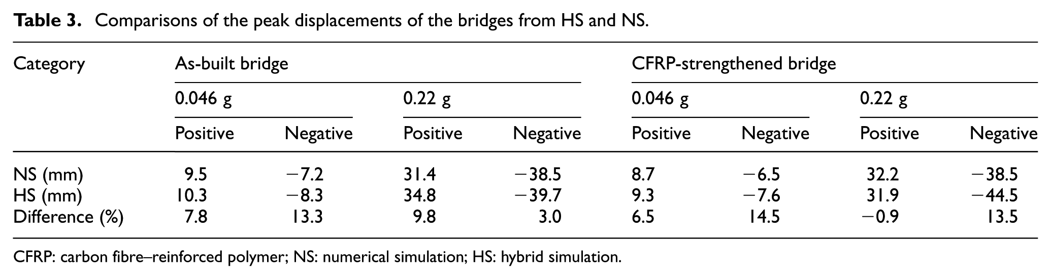
CFRP: carbon fibre–reinforced polymer; NS: numerical simulation; HS: hybrid simulation.
These discrepancies are mainly due to the errors introduced by the assumptions regarding energy dissipation and the modelling parameters in the numerical analyses. The experimental setup, including the instrumentation devices and the DAQ system, is also pertinent to the differences. For example, the HSs are not performed at a real-time scale, and the specimens are physically tested discontinuously. Specifically, the actuator imposes the command displacement to the specimen following a ramp-wise manner, which causes the column specimens to undergo force relaxation, and the energy dissipation of the specimen involves deviation.
Conclusion
In this article, HSs of an existing continuous RC girder bridge were conducted to investigate the strengthening and confining effects introduced by CFRP jackets on the plastic hinge region of the bridge columns. An OpenSees model of the entire bridge was employed to validate against the HS results, and through the results from the HSs and NSs, the observations are summarized as follows:
The HSS developed in this article is applicable to HS. It is worth noting that the original servo control system with a slow actuator can be used in HS because the effects of the inertial forces associated with the specimen on behalf of the experimental element can be taken into account by the mass assigned at the numerical substructure. This provides an approach to promote versatility of the quasi-static loading apparatus to study the seismic response of the bridges.
Conducting sequential HSs by applying earthquake motion to simulate seismic behaviour of the continuous RC girder bridge is feasible using OpenSees to model the numerical substructure. Although only one column specimen in each HS is physically tested to represent the experimental element for the hybrid analysis model, the response of the entire bridge during earthquakes can be obtained, and the behaviour of the experimental element is able to reflect the performance of the entire bridge.
Seismic reinforcement of the continuous RC girder bridge with wrapping FRP jackets in the plastic hinge region of bridge columns is an effective way to strengthen the ductile column, improving the seismic performance of the overall bridge.
In terms of the implementation of HS in a CFRP reinforcement study, this work is helpful for the development of a HS method in the structural experiment field. Nevertheless, there is still a need to refine and enhance the current system and flow. Continued investigations related to the online model updating scheme are necessary to mitigate the discrepancies between the experimental element and the similar numerical substructure. In addition, work is ongoing to address the ultimate behaviour of the CFRP-strengthened bridge, such as the curvature and ductility.
Footnotes
Declaration of Conflicting Interests
The author(s) declared no potential conflicts of interest with respect to the research, authorship and/or publication of this article.
Funding
The author(s) disclosed receipt of the following financial support for the research, authorship and/or publication of this article: This work was supported by the National Science Foundation of China (grant NO. 51278322 and 51308368) and the Education Department of Jiangsu Province (grant no. 13KJA560002). Any opinions, findings, conclusions or recommendations expressed in this material are those of the authors and do not necessarily reflect the views of the National Science Foundation of China and Education Department of Jiangsu Province.