
Abstract
In recent years, externally bonded carbon fibre–reinforced polymer has been considered an innovative way to strengthen steel structures attributed to its high strength-to-weight ratio, excellent corrosion resistance and fatigue performance. This article presents an experimental and numerical study on the fatigue behaviour of defected steel beams strengthened with carbon fibre–reinforced polymer laminates, with a special focus on the effect of interfacial debonding. Analytical modelling and numerical simulation confirmed that the interfacial debonding had a pronounced effect on carbon fibre–reinforced polymer strain and stress intensity factor at the crack front. After introducing interfacial debonding from experimental findings into the numerical analysis, the fatigue life and crack propagation versus cycle numbers of the specimens compared well with the test results. Based on the current experimental program, specimens with Sikadur 30 were more prone to debonding failure; therefore, Araldite 420 is suggested for strengthening schemes.
Introduction
Assessment and rehabilitation of fatigue behaviour of metallic structures is of great concern in the civil engineering community. Carbon fibre–reinforced polymer (CFRP) materials, attributed to the high strength-to-weight ratio, excellent corrosion resistance and fatigue performance, have been widely used in retrofitting of concrete structures (Kezmane et al., 2016; Wu and Liu, 2013). In recent years, researchers have explored CFRP application for fatigue strengthening of steel structures (Teng et al., 2012; Zhao and Zhang, 2007).
Extensive studies have demonstrated that externally bonded CFRP could effectively improve the fatigue behaviour of defected steel plates (Colombi et al., 2014; Feng et al., 2014; Jones and Civjan, 2003; Liu et al., 2009; Yu et al., 2013, 2014a). The overlay is helpful in sharing the far-field load and restraining the crack opening. Parametric analysis was performed on the mechanical properties of overlays and bond configurations to optimize the strengthening scheme (Brighenti, 2007; Täljsten et al., 2009; Wang et al., 2013; Yu et al., 2014b).
Research on strengthening of steel beams is comparatively less reported. Jiao et al. (2012) tested 21 initially cracked steel beams to investigate strengthening efficiency by sole welding and welding together with CFRP attachments. One layer of CFRP plate extended the fatigue life of the steel beams by approximately seven times. Four different retrofitting materials, including high-modulus carbon fibre–reinforced polymer (HM-CFRP) plates, high-strength carbon fibre–reinforced polymer (HS-CFRP) plates, steel-wire basalt-fibre–reinforced polymer (SW-BFRP) plates and welded steel plates explored by Wu et al. (2012), showed that HM-CFRP exhibited the best fatigue performance while SW-BFRP was the most cost-effective choice. Kim and Harries (2011) performed an experimental and numerical study on the flexural behaviour of CFRP repaired steel beams. An empirical model was proposed to estimate the fatigue response of the CFRP–steel interface. An unbonded CFRP prestressing technique was developed by Ghafoori et al. (2012).
Most previous research on fatigue strengthening with CFRP materials is relied on adhesive bonding. Experimental and analytical work has been carried out on the interfacial behaviour between CFRP and steel (Liu et al., 2010; Nozaka et al., 2005; Xia and Teng, 2005; Yu et al., 2012).
Hmidan et al. (2015) developed 1240 finite element models of wide-flange steel girders and extracted the stress intensity factor (SIF) at the crack front. A broad range of variables were taken into consideration to derive the correction factors for SIF. Strain compatibility between steel and CFRP was adopted in the numerical modelling. Fatigue tests on cracked steel beams repaired with CFRP plates by Colombi and Fava (2015) revealed the presence of a debonded area around the crack front, and consequently, an elliptical debonded region was introduced into the finite element model. The strain on the CFRP plates showed a good agreement with the test results. More recently, Zheng and Dawood (2016) presented an experimental and numerical analysis on CFRP strengthened steel plates and reported that the shape and size of the debonded zone greatly influenced the crack growth rate up to 54 times.
This study aims to investigate the fatigue behaviour of defected steel beams retrofitted by CFRP laminates, and the effect of interfacial debonding is emphasized. Analytical modelling and numerical simulation confirmed that interfacial debonding had a pronounced effect on CFRP strain and SIF at the crack front. Fatigue life and crack propagation with cycle numbers of the specimens compared well with the experimental findings with interfacial debonding taken into consideration. Based on current test results, the specimen with Sikadur 30 was more prone to debonding failure, and therefore, Araldite 420 became the preferred product for the strengthening scheme.
Experimental program
Four cracked steel beams were tested under fatigue loading in the Heavy Structures Testing Lab at City University of Hong Kong, China, among which two were unstrengthened and the other two were retrofitted with CFRP laminates.
Configuration of specimens
Figure 1 shows the specimen configuration and geometry. I-shaped beams with a cross section of 150 × 75 × 5×7 mm were selected in the test program. In order to simulate an initial damage, a notch of 15 mm long and 0.3 mm wide was artificially cut at the mid-span of the beam (Figure 1(b)). When strengthened, CFRP laminates, with a nominal cross section of 50 × 1.4 mm, were attached to the tension flange as depicted in Figure 1(a).
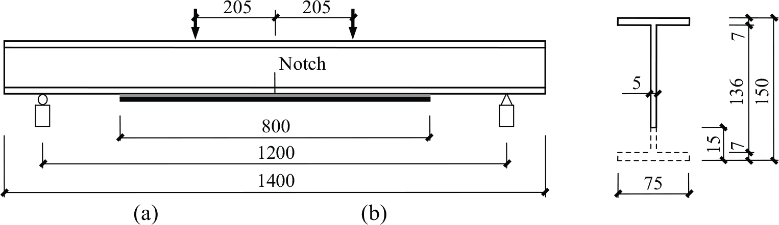
Specimen geometry (dimension in millimetre, not to scale): (a) strengthened specimen and (b) notch details.
Material properties
The steel beams used in the test were Grade Q345b. Tensile coupon specimens were first extracted from both the flange and web and then tested according to Australia Standard AS 1391-1991 (1991), as listed in Table 1. Normal modulus CFRP laminates, which were provided in rolls of 50 mm wide, were selected for the patch system. The mechanical properties were also determined through tensile coupon tests according to ASTM D3039/D3039M-08 (2008). Two types of structural adhesives, Araldite 420 and Sikadur 30, were adopted to bond the composite overlays. Their ultimate strength and tensile Young’s modulus based on the manufacturers’ data sheet are given in Table 1. Araldite 420 is a nonlinear adhesive with a smaller elastic modulus while Sikadur 30 is a linear one with a larger elastic modulus (Yu et al., 2012).
Measured material properties of steel, CFRP and adhesive.
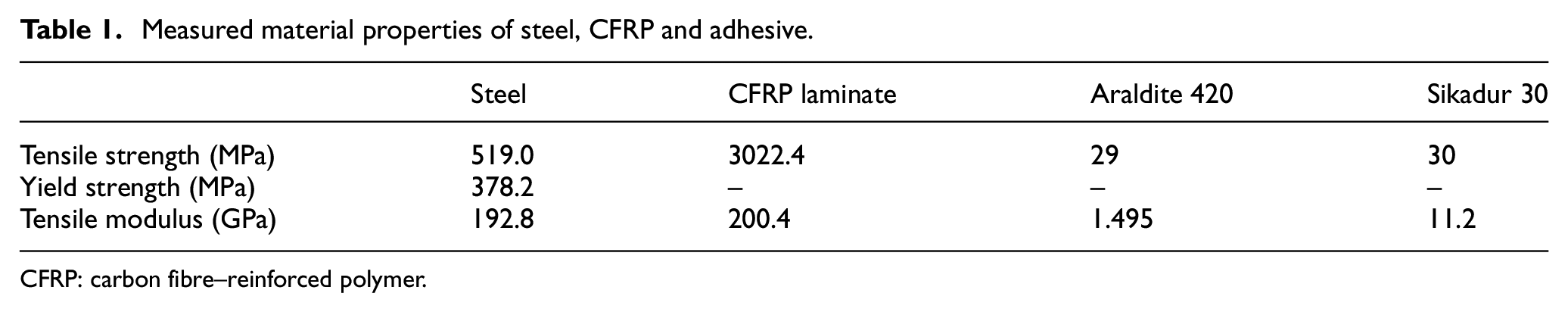
CFRP: carbon fibre–reinforced polymer.
Specimen preparation
The bond area on the tensile flange was sandblasted (coarse corundum power with a size from 1.5 to 2.0 mm at a pressure of 8 bar) to remove the rust and create a rough surface. Afterwards, the substrate was cleaned with high-pressure air and acetone. In addition, the surface of the CFRP laminate was wiped with acetone before attachment. The two components of the adhesive were carefully mixed according to the operation manual and used to glue the CFRP to steel. Measures were taken to ensure a uniform and desirable bond thickness around 0.5 mm (Yu and Wu, 2017). All specimens were cured at room temperature for 2 weeks before testing.
Fatigue loading and data acquisition
A four-point bending rig was selected to conduct the experiment. The distance between the two supports was 1200 mm, and the span between the two loading points was 410 mm. Compressive cyclic loading with a frequency of 6 Hz and a stress ratio R (minimum load/maximum load) of 0.1 with the waveform being sinusoidal was applied to the specimen through a spread beam. Three loading levels were selected in the test program, that is, 2–20, 3.5–35 and 7–70 kN (Figure 2). The load P here refers to the force applied by the actuator to the spread beam.
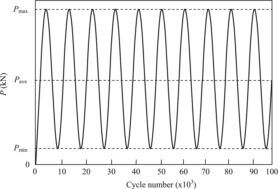
Fatigue load spectrum.
Strain gauges were attached to the potential crack path on the beam web at a certain interval to detect the crack propagation against fatigue cycle numbers. When the crack grew to the position where a strain gauge attached, there would be sharp change in the strain reading.
Besides fatigue cycles, static loads were applied at the beginning of the test and after a certain number of fatigue cycles. The specimens were loaded from zero to the maximum force of the fatigue load and then unloaded to zero. During these loops, the digital image correlation (DIC) system was used to monitor the strain distribution along the CFRP patch (Wu and Jiang, 2013).
Test results
Table 2 presents a summary of the test program and results. Beams 1 and 2 were bare specimens without strengthening. As the cycle number increased, the initial slot began to propagate towards the compression flange. When the crack reached a certain length, the reduced cross section of the beam could not bear the applied loading, and the specimen ruptured to failure.
Fatigue life of test specimens.
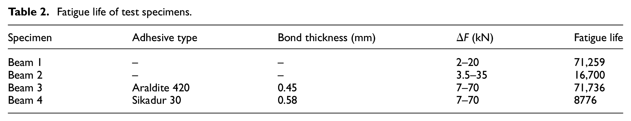
Beams 3 and 4, which were strengthened with CFRP materials, showed a significantly retarded crack propagation in comparison with the non-strengthened specimens. As a result of stress concentration, interfacial debonding within the adhesive layer was initiated beneath the notch and expanded to the two ends of the CFRP laminate. Compared to Beam 4, Beam 3 (repaired with Araldite 420) had a slower debonding process. Even when the crack reached the intersection of the compressive flange and web, the debonding length was still limited and extended slowly. The specimen finally fractured when the debonded zone reached a certain value. However, in Beam 4 which was retrofitted with Sikadur 30, the debonded zone grew much more rapidly with the fatigue cycles. Before the crack developed to the web tip, the CFRP patch was suddenly detached from the steel and the crack spread to the beam web. Cohesive failure (adhesive layer failure) was observed for both specimens, and Araldite 420 was found to have a higher interfacial fracture energy and rougher bond than Sikadur 30 (Yu et al., 2012).
Figure 3 depicts the crack propagation with fatigue cycles of all the specimens. The horizontal axis and vertical axis represent the fatigue cycle numbers and the crack length measured from the tension soffit to the crack front, respectively. The difference between Beams 1 and 2 as shown in Figure 3(a) indicates that a larger fatigue loading can lead to a significantly increased fatigue crack growth (FCG) rate and consequently a considerably reduced fatigue life. Figure 3(b) shows that Beam 3 with CFRP retrofitting endured many more cycles under a doubled fatigue loading in comparison with Beam 2, which demonstrates that strengthening by CFRP can effectively improve the fatigue behaviour of defected steel beams. An apparent difference was observed between specimens repaired with different structural adhesives. Araldite 420 yielded a much slower debonding extension as well as slower crack development compared to Sikadur 30.
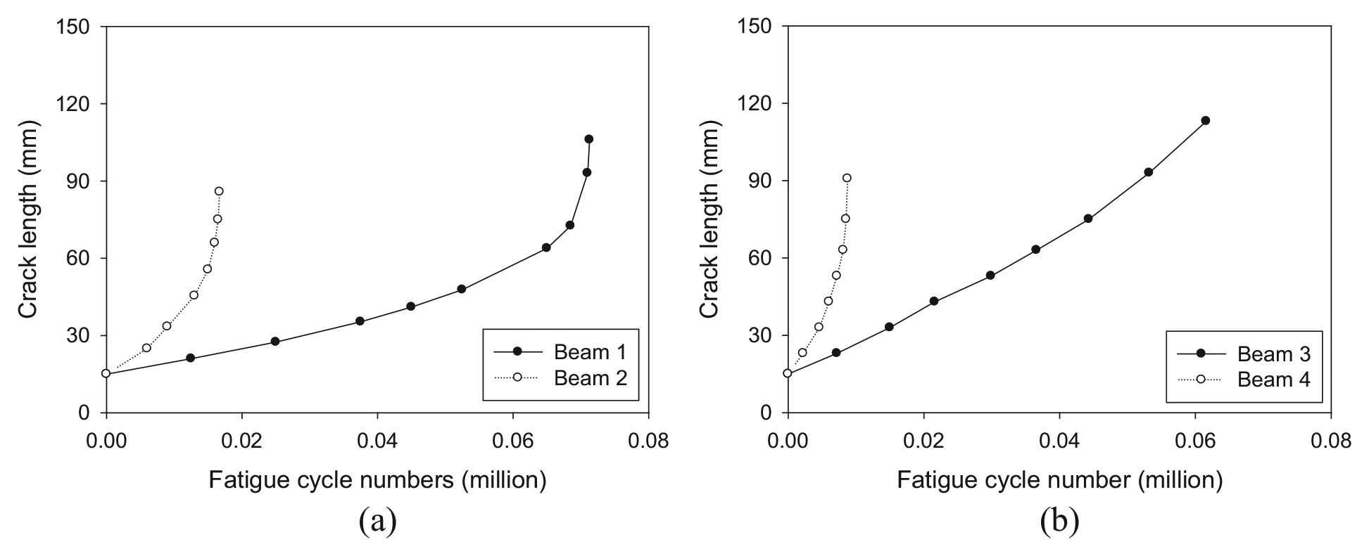
Fatigue crack propagation: (a) steel beams without strengthening and (b) steel beams strengthened with CFRP laminates.
During the static loading processes in between fatigue cycles, the strain fields on the CFRP patch of Beams 3 and 4 were captured by the DIC system and are shown in Figures 4 and 5. High strain concentration occurred at the centre notch. As the crack length increased, the high strain zone spread towards the free ends of the laminate.
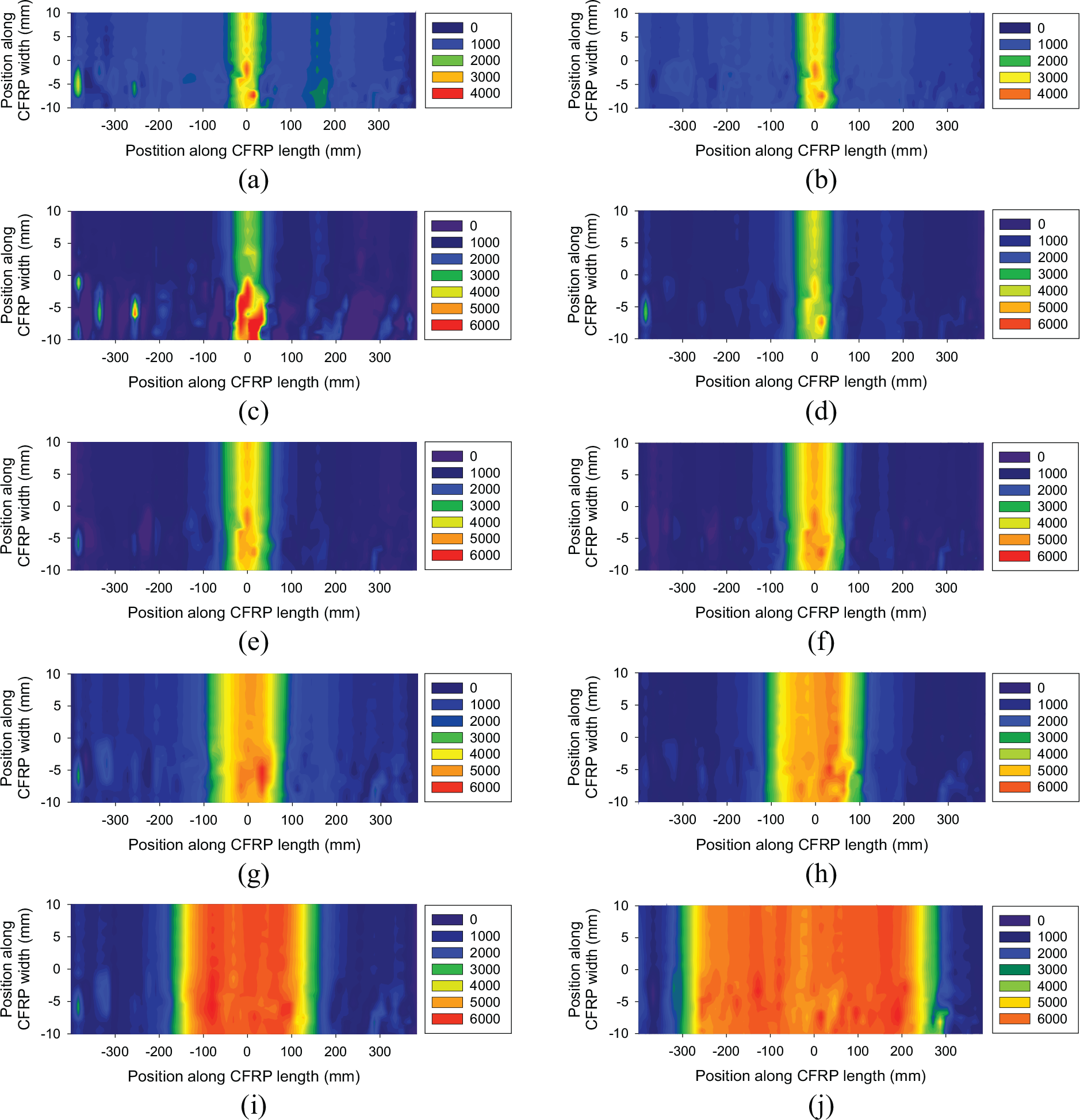
Strain distribution on the CFRP laminate of Beam 3: (a) a = 15 mm, (b) a = 23 mm, (c) a = 33 mm, (d) a = 43 mm, (e) a = 53 mm, (f) a = 63 mm, (g) a = 75 mm, (h) a = 93 mm, (i) a = 113 mm and (j) a = 143 mm.
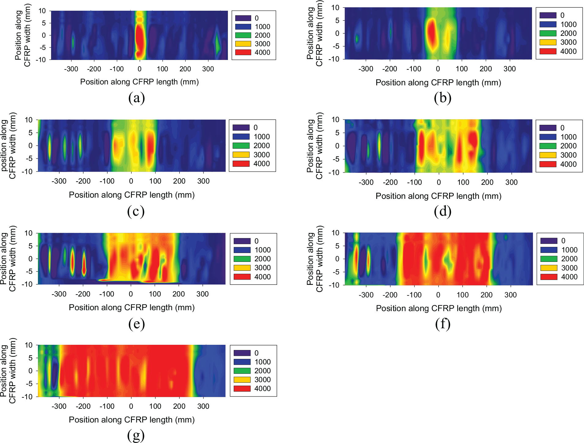
Strain distribution on the CFRP laminate of Beam 4: (a) a = 15 mm, (b) a = 23 mm, (c) a = 33 mm, (d) a = 43 mm, (e) a = 53 mm, (f) a = 63 mm and (g) a = 75 mm.
The variations in the strain plateau depicted by the same colour in Figures 4 and 5 indicate the development of interfacial debonding. The debonding length versus crack length and fatigue cycles are further extracted and shown in Figures 6(a) and (b), respectively. It was found that the specimen repaired by Sikadur 30 was more prone to debonding and the expansion of debonded zone with crack length was much faster than that in the specimen strengthened by Araldite 420. This indicated that Araldite 420 is preferred for CFRP external bonding applied in steel strengthening.
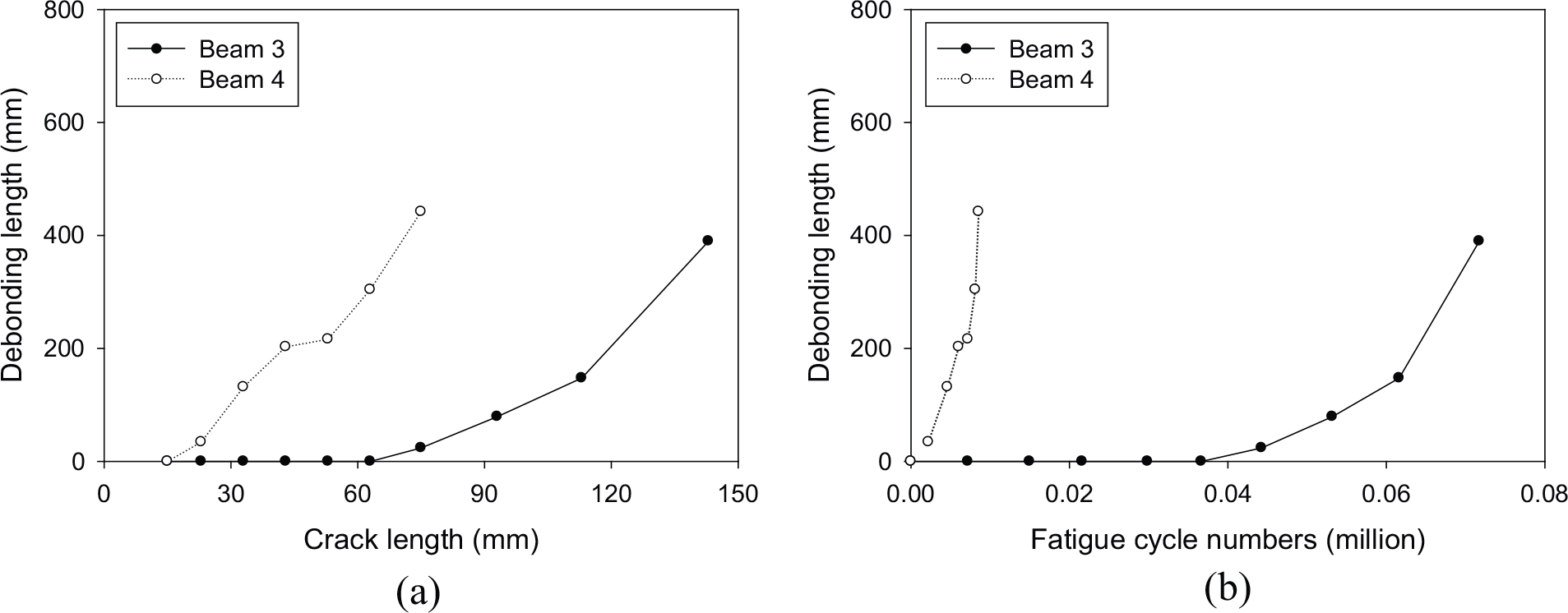
Comparison of debonding process between Beams 3 and 4: (a) debonding length versus crack length and (b) debonding length versus fatigue cycle numbers.
Analytical modelling
With the presence of retrofitting materials, the stress field in a steel beam is reduced, leading to a retarded crack propagation of the specimen. Therefore, it is of great importance to accurately evaluate the stress distribution between the steel component and attached overlay. With respect to the fatigue load applied in the current program, the materials in this work (steel, CFRP and adhesive) were all considered to be under the linear elastic stage. A simple analytical modelling proposed by Colombi and Fava (2015) is used in this section for analytical study. The model is based on the following assumptions:
All materials including steel, CFRP and adhesive are elastic.
A plane section remains plane during bending.
Perfect bonding occurs between steel and CFRP, that is, no slippage, is considered.
Consequently, the strain distribution along the cross section is displayed in Figure 7.
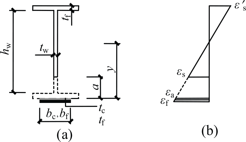
Strain distribution on the cross section: (a) cross section and (b) strain distribution.
Analysis of the cracked section
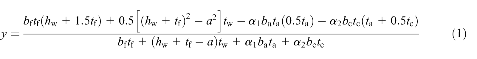
For such a composite cross section, the neutral axis is first derived as expressed by equation (1)
The second moment of area, I, of the composite section is composed of three parts, that is, Is, Ic and Ia, which are expressed by

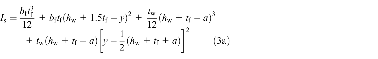

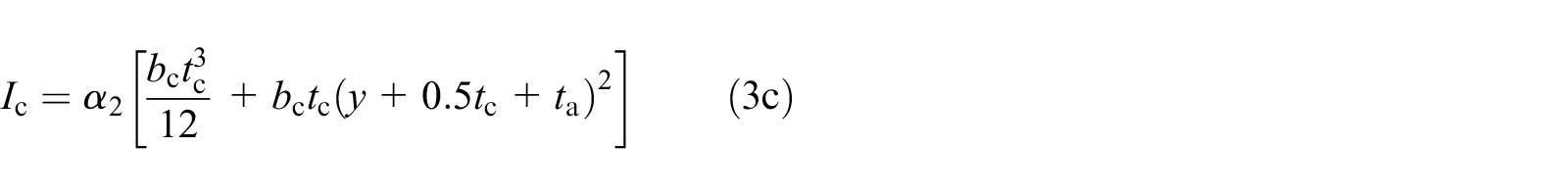
Substitution of equations (3a) to (3c) into equation (2) results in equation (4). Finally, the strain on CFRP laminate beneath the initial slot is calculated by equation (5)
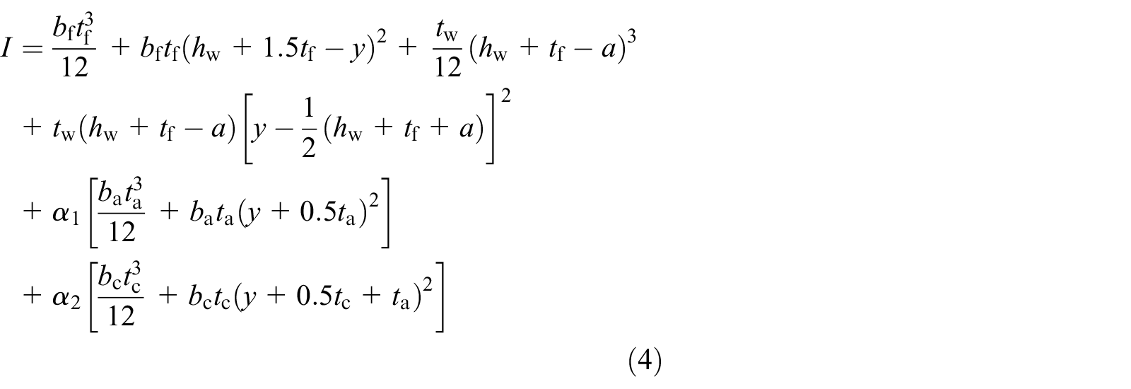

where y represents the distance from the neutral axis to the bottom flange of the steel section; a is the crack length measured from the tensile soffit to the crack tip; b and t indicate the width and thickness, respectively; I is the second moment of area; E is the elastic modulus; ε is the strain; the subscript s, f, w, a and c denote the steel beam, beam flange, beam web, adhesive and CFRP, respectively; α1 and α2 are elastic modulus ratios, which are defined as Ea/Es and Ec/Es, respectively.
Comparison between analytical results and test data
Figure 8 plots the comparison of the strain on the CFRP laminate against the crack length between the analytical results and experimental findings for Beams 3 and 4. Figure 8(a) shows that when the crack length a increases from 15 to 63 mm, the strain results obtained from the analytical solution compare well with the test data of Beam 3. However, a significant difference occurs thereafter, and the analytical calculation overestimates the strain on the CFRP by as much as 16%. The experimental axial strain at the mid-span of the CFRP laminate of Beam 4 is significantly lower than the analytical one from the beginning to the final failure.
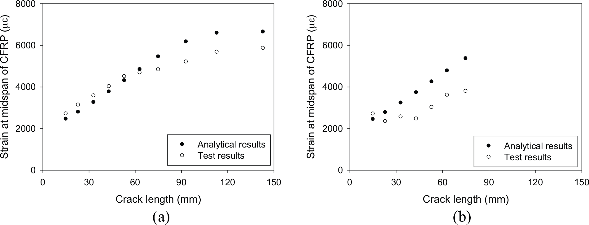
Comparison between analytical results and test data: (a) Beam 3 and (b) Beam 4.
This phenomenon is mainly due to the development of the debonded zone. Considerable interfacial debonding is observed after certain loading cycles in Figures 4 and 5, which violates the plane section’s remaining plane assumption. For Beam 3, the high strain region keeps stable for the crack length ranging from 15 to 63 mm and shows remarkable extension to both ends of CFRP from a = 75 mm. For Beam 4, the strain concentration quickly progresses from the initial beginning. These trends are consistent with the variation of difference between analytical and test results shown in Figure 8.
After the occurrence of significant interfacial debonding, slip between CFRP and steel was observed from experimental tests, as reported in Yu and Wu (in preparation). Therefore, the assumption of strain compatibility (Figure 7) becomes invalid. The analytical solution without considering the slip between CFRP and steel substrate would overestimate the strain on the CFRP laminate, and the difference becomes more pronounced with crack propagation, leading to an overestimation of the strengthening efficiency. This analysis also suggests that debonding has an unfavourable effect on repair efficiency. In Colombi and Fava (2016), analytical solution to evaluate the stress on the CFRP with the slip effect taken into consideration was proposed.
Numerical modelling
Finite element modelling
Three-dimensional finite element modelling was developed to assess the fatigue behaviour of the test specimens using the commercial software ABAQUS (2010). The contour integral method was used to define the onset of cracking and to calculate the output parameter required for computation of SIF. With consideration of the symmetric specimen configuration and boundary condition, a quarter-scale model with symmetrical constraints on corresponding boundaries, as shown in Figure 9(a), was adopted for the analysis. The geometry and dimensions of the models were the same as those in the experimental program. A load was applied at the position of the spread beam (Figure 9(b)).
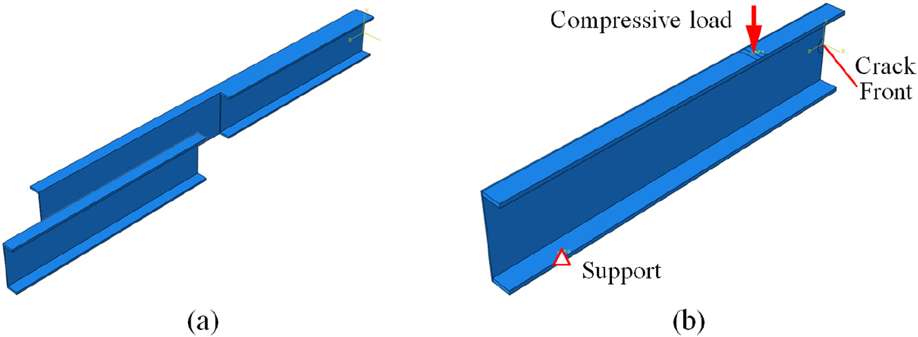
Finite element modelling: (a) one quarter model and (b) boundary conditions.
The fatigue loading applied in the test program was relatively small so that the steel and CFRP were under a linear elastic stage. Consequently, linear elastic constitutive laws were adopted for the materials. The steel had a Young’s modulus of 192.8 GPa and a Poisson’s ratio of 0.3, and the CFRP had a Young’s modulus of 200.4 GPa and a Poisson’s ratio of 0.3. Araldite 420 and Sikadur 30 had a Young’s modulus of 1.495 and 11.2 GPa, respectively. A Poisson’s ratio of 0.36 was adopted for the structural adhesives (Fawzia, 2007).
Three-dimensional quadratic brick elements (C3D20R) were selected to mesh the steel plate, adhesive layer and CFRP laminate. The model of the strengthened beam consisted of 29,952 elements and 147,413 nodes. The stress and strain singularities at the crack front were simulated using the 15-node wedge elements collapsed from the 20-node brick elements, as displayed in Figure 10(a). Sixteen elements (11.25° per element) were assigned around the semi-circumference to create a sharp crack front. The detailed mesh around the crack front is depicted in Figures 10(b) and (c).
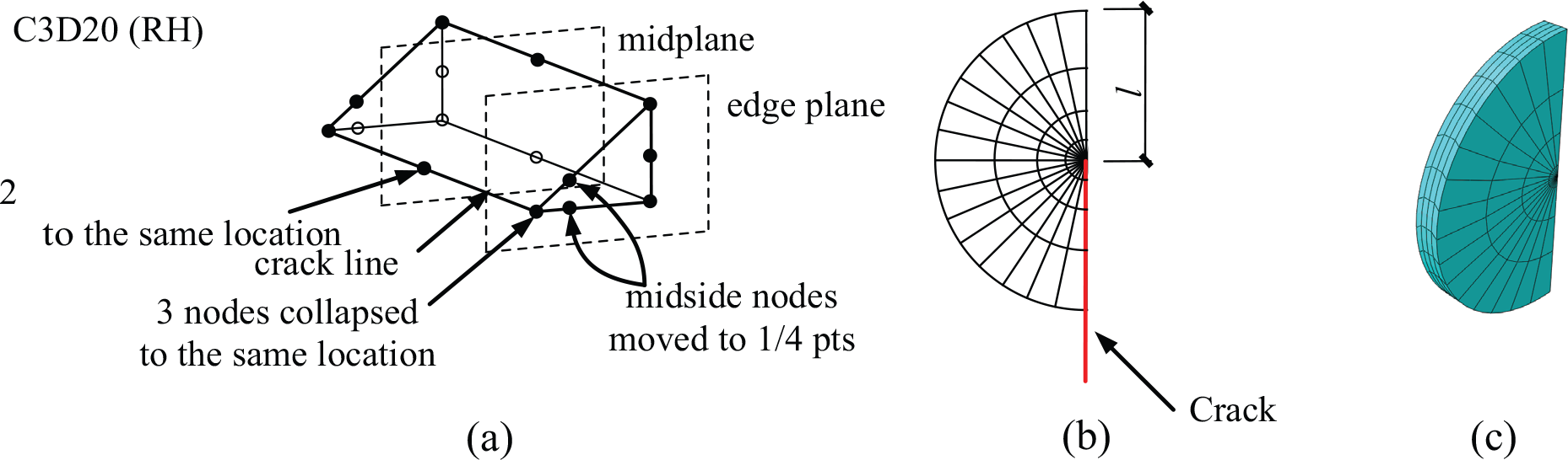
Collapsed three-dimensional element and crack front mesh: (a) 15-node wedge elements, (b) crack front mesh size and (c) crack front mesh.
Mesh dependency analysis
A mesh dependency analysis was carried out to obtain a reasonable size of the element around the crack front. Models with ratios of the crack front element size l to the crack length a ranging from 0.025 to 0.25 were computed. The case of a bare steel beam without strengthening loaded under 20 kN was adopted and two crack lengths, that is, 30 mm (a/h = 0.2, h is the beam height) and 75 mm (a/h = 0.5), were selected. A total of 16 cases were calculated and the corresponding results are presented in Figure 11. It was found that based on the current numerical results, the SIF had little dependency on the element size ratio. Consequently, the ratio value of 0.20 was used for the present study.
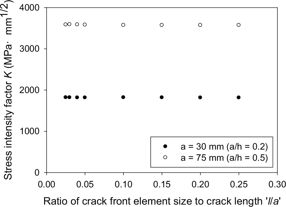
Stress intensity factor versus crack front element size to crack length ratio.
Validation of the numerical simulation
The theoretical solution of a steel plate under bending (Figure 12) was used to validate the numerical analysis. The SIF value of a steel plate with a mid-span crack was calculated by equation (6) (Boresi and Schmidt, 2003)

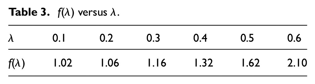
where λ is the ratio of the crack length to the plate height and σ is the far-field stress, which are expressed by equations (6b) and (6c), respectively. f(λ) is a correction factor, and its value versus λ is given in Table 3


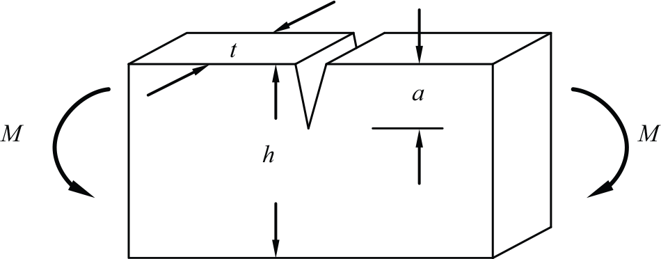
Schematic diagram of the classical solution with respect to a steel plate under bending.
f(λ) versus λ.
A finite element model similar to that of the steel beam was adopted here, and the only difference was that the beam flanges were excluded. Consequently, the steel plate was 700 mm long, 150 mm high and 2.5 mm thick. It was loaded under 20 kN and the comparison between the theoretical solution and numerical results is depicted in Figure 13. It is indicated that the two agreed well with the ratio of the crack length to plate height increasing from 0.1 to 0.6.
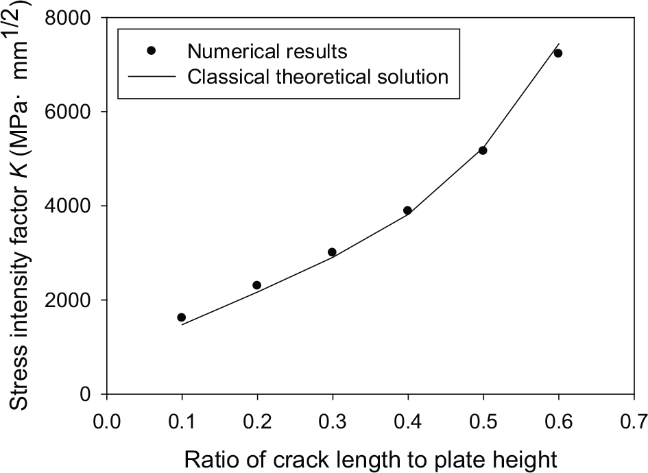
Comparison between numerical results and classical theoretical solution.
Effect of interfacial debonding
It was observed from the experimental study that interfacial debonding developed under fatigue cycling, and the analytical study demonstrated that the debonding had a detrimental effect on the strengthening scheme. The length of the debonded region was considered to dominate the performance of the repaired steel beam and, therefore, was focused in this section. Finite element models with different lengths of the debonded zone were studied and the SIF at the crack front were extracted. The debonded region was modelled without connection between the steel and CFRP while perfect bond was assumed for the remaining area. It was found that the strain distribution was approximately uniform in the width direction of the patch; therefore, a rectangle shape of the debonded zone was assumed for the sake of simplicity. A uniform bond thickness of 0.5 mm was adopted in all cases. The SIF results versus the length of debonded region of the beams loaded under 70 kN are displayed in Figure 14.

Stress intensity factor versus length of debonding region: (a) a = 30 mm (a/h = 0.2) and (b) a = 75 mm (a/h = 0.5).
Similar to Figure 11, two crack lengths of 30 and 75 mm as well as two structural adhesives of Araldite 420 and Sikadur 30 were adopted. Six lengths of debonded region, that is, 0 (no debonding), 20, 40, 60, 80 and 100 mm were analysed. The debonding length here is for a quarter-scale beam and hence is half of the total debonding length of the entire beam.
It was found that the SIF notably increased with the increase of the debonding length, especially in the case with a larger crack length. When the crack length was 30 mm, the SIF was increased from 1595 MPa mm1/2 (Sikadur 30, debonding length of 0 mm) to 4434 MPa mm1/2 (Sikadur 30, debonding length of 100 mm) and the corresponding variation percentage was 178%. When the crack length reached 75 mm, a more significant effect of the debonding length on the SIF was demonstrated as the SIF was improved by 360% for the specimen repaired by Sikadur 30.
Figure 14 shows that at a certain crack length, provided the debonding lengths of the specimens with Araldite 420 and Sikadur 30 are the same, the one with Sikadur 30 would lead to a slightly smaller SIF at the crack front in comparison with that with Araldite 420 attributed to the larger stiffness of Sikadur 30. However, in reality, specimens bonded with Sikadur 30 were more prone to debonding with a larger debonded zone under same cycles of loading due to the smaller interfacial fracture energy, leading to a poorer performance in comparison with Araldite 420.
Numerical analyses of the test specimens
For the unstrengthened specimens, symmetric constraints were applied to the corresponding boundaries, and the crack face was left free. For the strengthened specimens, both the scenarios of perfect bonding and partial debonding were analysed. The length of debonded zone observed from the experimental results was introduced into the numerical simulation for the scenario of partial debonding. The corresponding SIF at the maximum force of the fatigue load is plotted in Figure 15.

Stress intensity factor versus crack length: (a) Beams 1 and 2, (b) Beam 3 and (c) Beam 4.
It was interesting to see that the SIF of the bare steel beams increased quickly with the crack length while the strengthened specimens showed different variation trends. In the perfect bonding cases, the SIF decreased with the crack length. This was because SIF depends on both far-field loading and crack length as expressed by equation (6a). As the crack propagated to the compressive flange, the CFRP shared more of the far-field loading, resulting in a decreased stress field in the steel beam. Without considering the interfacial debonding, the stress field on the CFRP was significantly overestimated and the reduction of the stress field in the steel beam governed the variation trend of SIF.
After the debonding was considered in the numerical simulation, the SIF again increased with the crack length. In Beam 3, when the crack length was less than 75 mm, no apparent debonding was found based on the experimental findings; therefore, no debonding was set in the models; thus, the SIF results of the two scenarios coincided.
With the SIF derived from the numerical simulation, the fatigue behaviour of the test specimens was predicted based on the linear elastic fracture method (LEFM). Paris Law (JSSC, 1995) as expressed by equation (7) was adopted and the fatigue life was integrated based on equation (8)

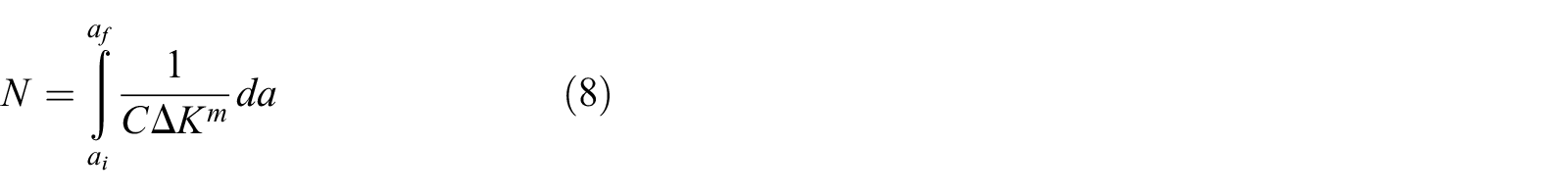
where a is the crack length, N is the number of fatigue cycles, C and m are material constants that are determined experimentally, ΔK is the SIF range at the crack front and ai and af are the initial crack size and final crack size, respectively.
For the bare steel beams without strengthening, c and m were taken as 3.98 × 10⁻¹³ and 2.88, respectively (da/dN in mm/cycle and ΔK in MPa mm1/2), according to the recommendation by British Standards Institution, mean curve (BS 7910:2005); for the steel beams strengthened by CFRP laminates, c and m were taken as 6.77 × 10⁻¹³ and 2.88, respectively (da/dN in mm/cycle and ΔK in MPa mm1/2), according to the recommendation by British Standards Institution, mean + 2SD (BS 7910:2005).
Figure 16 shows the comparison of fatigue life between prediction results and test data. It was found that the SIF derived from the numerical simulation could be used to conservatively predict the fatigue life of both bare steel beams and strengthened components. All the deviations were less than 20% except for Beam 3 (23.8%). Note that the cases displayed in Figure 16 took the interfacial debonding into consideration. The results corresponding to the scenario of perfect bonding was dramatically different from the test data and was, therefore, excluded from the figure. The test fatigue life of Beams 3 and 4 was 71,736 cycles and 8,776 cycles, respectively, while the calculated results based on the perfect bonding were 915,453 and 467,236 cycles, respectively. It was, therefore, concluded that the interfacial debonding with crack propagation should be taken into consideration; thus, future research is planned on the progress of the deboning zone with fatigue cycles.
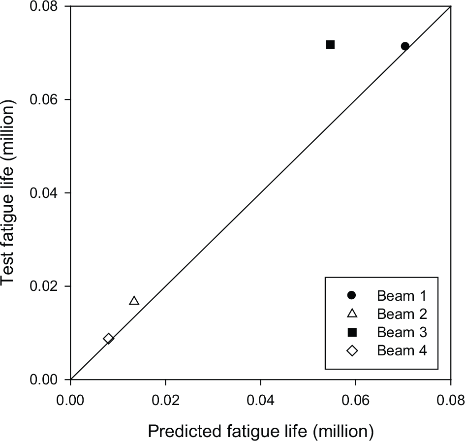
Comparison of fatigue life between predicted results and experiential data.
The fatigue crack propagation with cycle numbers of the four specimens is plotted in Figure 17, which also confirms that the numerical simulation with interfacial debonding considered was feasible for estimating the fatigue behaviour of the steel beams.
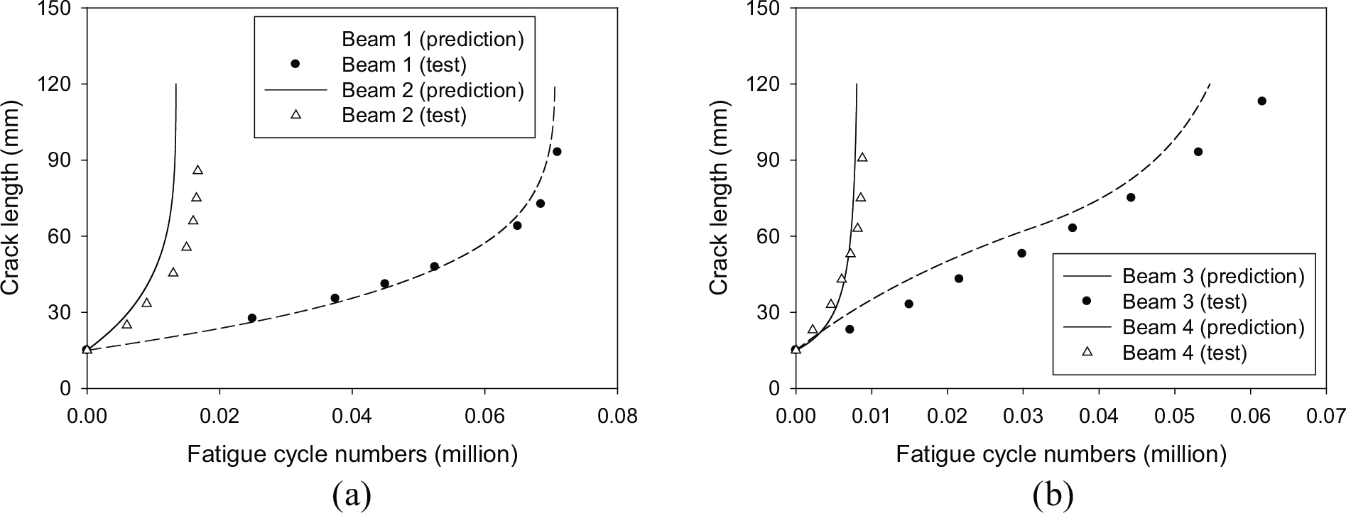
Comparison of fatigue crack propagation between predicted results and experiential data: (a) Beams 1 and 2 and (b) Beams 3 and 4.
Conclusion
In this article, an experimental and numerical study on the fatigue behaviour of defected steel beams strengthened with CFRP laminates was presented. The effect of interfacial debonding was focused. The following observations can be made and conclusions drawn.
Specimens strengthened with CFRP laminates witnessed apparent interfacial debonding during the experimental study. Compared to Sikadur 30, Araldite 420 with a larger interfacial fracture energy was recommended for the strengthening scheme. Specimens repaired with Sikadur 30 were more prone to interfacial failure.
With the presence of interfacial debonding, the plane section assumption was no longer valid. The analytical modelling based on the perfect bonding overestimated the field load shared by the CFRP materials, which would lead to an overestimated strengthening efficiency.
Parametric analysis of the debonding length showed that the SIF increased considerably with the increase of the debonding length, which implied that it is of great importance to accurately assess the progress of interfacial debonding with fatigue cycles. Future research is planned to study the development of interfacial debonding under cyclic loading. With the debonding length from experimental findings introduced into the numerical modelling, the fatigue life and crack propagation versus cycle numbers agreed well with the test results.
Footnotes
Acknowledgements
The authors wish to express their heartfelt appreciation to Prof. Xiang-Lin Gu from Tongji University and Prof. Xiao-Ling Zhao from Monash University for supervising the present work. Thanks are due to all the technical staff in the Heavy Structures Testing Lab at City University of Hong Kong, especially Mr Chan Wan Tong Allan and Mr Ernest Cheung, for their assistance in carrying out the tests.
Declaration of Conflicting Interests
The author(s) declared no potential conflicts of interest with respect to the research, authorship and/or publication of this article.
Funding
The author(s) disclosed receipt of the following financial support for the research, authorship and/or publication of this article: The work described in this article was supported by the National Natural Science Foundation of China (project no. 51508406) and the Research Grant Council, Hong Kong Special Administrative Zone, China (project no. CityU124113).