
Abstract
Fibre-reinforced polymer–concrete–steel hybrid multi-tube concrete columns are a new form of columns recently proposed at the University of Wollongong. An multi-tube concrete column consists of an external fibre-reinforced polymer tube and a number of circular internal steel tubes, with the space inside all the tubes filled with concrete. This article presents the first ever experimental study on square multi-tube concrete columns. The experimental program included a total of 14 stub column specimens tested under axial compression, with the test variables being the thickness of the external fibre-reinforced polymer tube, and the dimensions and configuration of the internal steel tubes. The test results demonstrated that the concrete in the square multi-tube concrete columns was very effectively confined by the multiple tubes, and that the buckling of the internal steel tubes was completely prevented, leading to full structural utilization of the materials and a very ductile response. The test results also showed that the behaviour of the concrete in the square multi-tube concrete columns was significantly superior to that in the corresponding square concrete-filled fibre-reinforced polymer tubes, in terms of the compressive strength, the ultimate axial strain and the stiffness of the second branch of the stress–strain curve. A simple analytical model proposed for the axial load-axial strain curve of square multi-tube concrete columns is also presented and is shown to provide reasonable and conservative predictions of the test results.
Introduction
In the past two decades, fibre-reinforced polymer (FRP) composites have emerged rapidly as a durable construction material. One important application of FRP for new construction is the combined use of an FRP tube, concrete and steel to form hybrid FRP tubular structural members (Teng et al., 2007; Yu et al., 2016a). In such structural members, the FRP tube serves as a confining device for the concrete as well as a protective skin against corrosion, leading to excellent ductility and durability. Extensive research has been conducted on various forms of hybrid FRP tubular members, including concrete-filled FRP tubes (CFFTs) (Fam and Rizkalla, 2001; Ozbakkaloglu, 2013; Ozbakkaloglu and Xie, 2016; Yu and Teng, 2011; Zohrevand and Mirmiran, 2012) and hybrid double-tube concrete columns (DTCCs) with an FRP outer tube, a steel inner tube and concrete filled in the space inside both tubes (Teng and Yu, 2015; Zhou et al., 2017).
More recently, a new form of hybrid FRP tubular members, namely, FRP-concrete-steel hybrid multi-tube concrete columns (MTCCs), was proposed at the University of Wollongong (Yu et al., 2016b). An MTCC consists of an external FRP tube and a number of circular internal steel tubes, with the space inside all the tubes filled with concrete (Figure 1(a) to (d)). The multiple internal steel tubes can be connected to each other by angle brackets or point welding at discrete locations to facilitate their placement prior to casting concrete. In MTCCs, the three materials (i.e. FRP, concrete and steel) are combined in an optimal manner. The use of small steel tubes eliminates the difficulties associated with the manufacturing, transportation and installation of large steel tubes. Other advantages of MTCCs include (1) excellent ductility as the concrete is effectively confined by the small circular steel tubes in addition to the external FRP tube, (2) excellent durability because of the use of a corrosion-resistant FRP tube which protects the steel and concrete, (3) complete elimination of the need for formwork and (4) opportunity of optimizing the locations of the small steel tubes for improved structural performance. Yu et al. (2016a) presented the first experimental study on circular MTCCs with a circular external FRP tube and demonstrated their excellent structural performance.
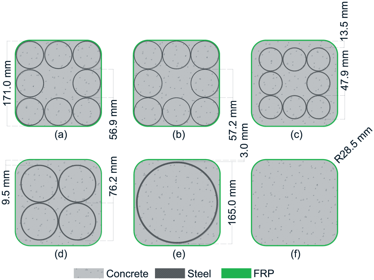
Cross-sections of test specimens: (a) Specimens M8A-3-I, II and M8A-4-I, III; (b) Specimens M8B-3-I, II; (c) Specimens M8C-3-I, II; (d) Specimens M4D-3-I, II; (e) Specimens D1E-3-I, II and (f) Specimens C-3 and C-4.
This article presents the first ever experimental study on square MTCCs with a square external FRP tube (Figure 1(a) to (d)). In square MTCCs, the concrete inside the circular steel tubes is effectively confined; the multiple concrete-filled steel tubes (CFSTs) also form a stiff ‘wall’ to confine the concrete surrounded by them. Therefore, the concrete in square MTCCs is expected to perform better than normal square FRP-confined concrete columns in which the concrete near the four flat sides is not effectively confined (Lam and Teng, 2003). The experimental program and results of the present study are discussed in the following sections, with a particular focus on the effectiveness of confinement to the concrete.
Experimental program
Test specimens
A total of 14 specimens were prepared and tested under axial compression, including five pairs of MTCC specimens (Figure 1(a) to (d)), one pair of DTCC specimens (Figure 1(e)) and two CFFT specimens (Figure 1(f)) for comparison; each pair of MTCC or DTCC specimens included two nominally identical specimens. All the specimens had a height of 500 mm and a square FRP outer tube; the FRP tube had a side length of 171 mm (measured from the inner side of the tube) and four rounded corners with a radius of 28.5 mm (Figure 1). The main test variables included the type and configuration of steel tubes, as well as the thickness of FRP tube. The five pairs of MTCC specimens covered four types of steel tubes (A to D, see Tables 1 and 2) and two tube configurations (i.e. eight-tube configuration and four-tube configuration). The cross-sections of the specimens are shown in Figure 1 while the details of the specimens are summarized in Table 1. In Table 1, each specimen is given a name, which includes the following in sequence: (1) a letter ‘M’, ‘D’ or ‘C’ to represent MTCC, DTCC and CFFT, respectively; (2) a number ‘1’, ‘4’ or ‘8’ to represent the number of steel tubes in the specimens; (3) another letter ‘A’ to ‘E’ to represent the type of the steel tubes whose details are given in Table 2 and (4) another number ‘3’ or ‘4’ to represent the number of plies of fibres in the FRP tube. The last Roman numeral in the specimen names is used to differentiate two nominally identical specimens.
Details of specimens.
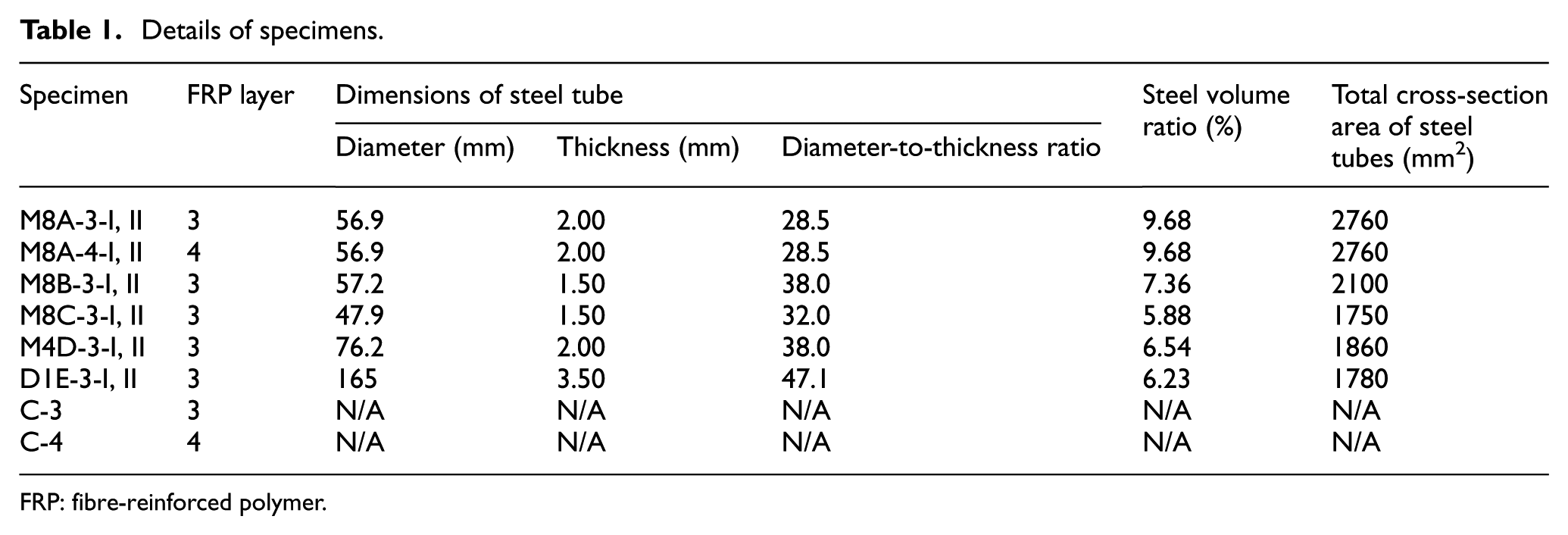
FRP: fibre-reinforced polymer.
Material properties of steel tubes.
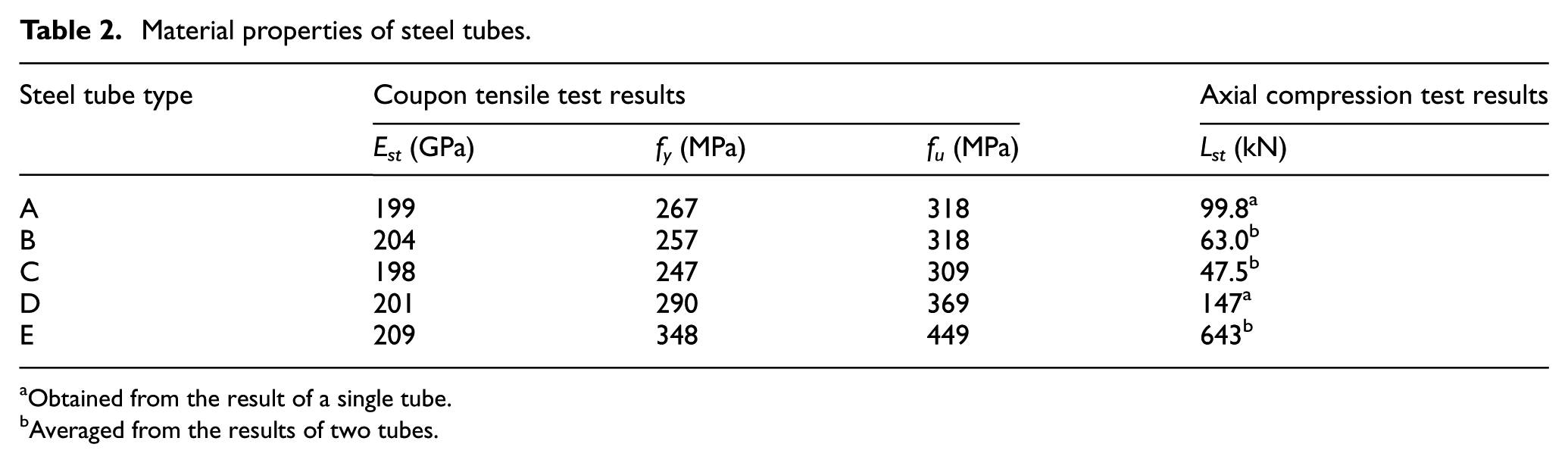
Obtained from the result of a single tube.
Averaged from the results of two tubes.
Material properties
Self-compacting concrete with a maximum aggregate size of 10 mm was used to ensure the quality of concrete casting. Two types of standard tests, namely, the slump flow test and the J-ring test, were conducted to examine the workability of fresh concrete in accordance with AS 1012.3.5:2015 (2015). The slump flow and the J-ring flow were found to be 505 and 480 mm, respectively. During the concrete casting, caution was taken to minimize the visible voids inside the columns, especially for the parts with a small space. To obtain the mechanical properties of unconfined concrete, three standard concrete cylinders (150 mm in diameter and 300 mm in height) were tested in accordance with AS 1012.9:2014 (2014); the average elastic modulus, compressive strength
For each type of steel tubes, three tensile coupons were prepared and tested in accordance with BS 18:1987 (1987). The coupons were all cut from a steel tube along the longitudinal direction and had a dog bone shape. The average values of elastic modulus Est, yield stress fy and tensile strength fu of the steel tubes, obtained from the coupon tests, are summarized in Table 2. In addition, for each type, one (for types A and D) or two (for types B, C and E) hollow steel tubes were tested under axial compression; the hollow tube specimens all had a height of 500 mm, which is the same as that of the steel tubes in the MTCC specimens. All the hollow steel tubes experienced large plastic deformation before failure occurred by a combination of overall buckling and local buckling (see Figure 2(a)), except for the hollow tubes of type E which failed by local buckling in the elephant’s foot mode (see Figure 2(b)) due to their relatively small length-to-diameter ratio. The average ultimate axial loads Lst found from the hollow tube tests are also summarized in Table 2.
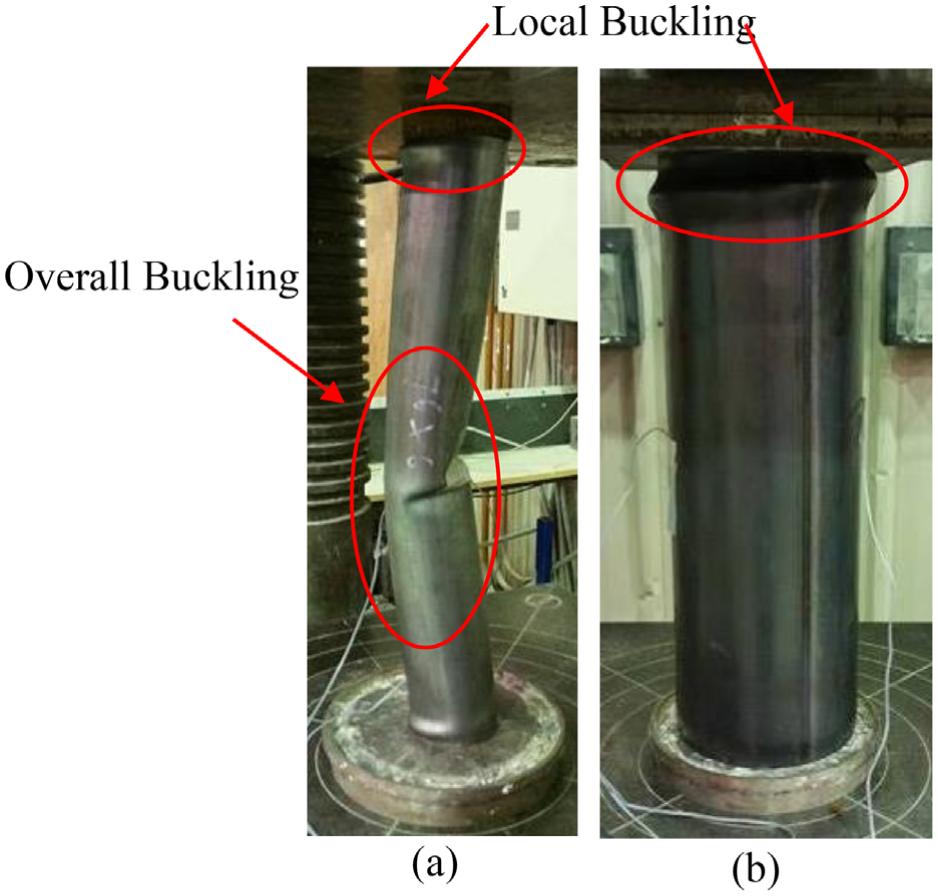
Steel tubes after test: (a) Type D and (b) Type E.
The FRP tubes were made via a wet-layup process using glass fibre sheets, which had 90% of fibres in the major direction (lateral direction of the tubes) and 10% fibres in the minor direction (axial direction of the tubes). Three FRP coupons were prepared and tested under tension in the major direction, in accordance with ASTM D3039/D3039M (2014). The FRP material was found to have an average elastic modulus of 74.0 GPa, an average tensile strength of 1490 MPa and an average rupture strain of 0.0192, all in the major direction, based on a nominal thickness of 0.174 mm per ply.
Preparation of specimens
The preparation process of the MTCC and DTCC specimens included the following steps: (1) cutting of the steel tubes into the desired lengths and welding them at point close to the two ends of the steel tubes to form the designed configuration (for MTCCs only); (2) attaching strain gauges at the mid-height of the outer surface of the steel tubes; (3) prefabricating FRP tubes via a wet-layup process with an overlapping length of 110 mm on a flat side of the tubes; (4) preparation of the moulds, which each consisted of an external prefabricated FRP tube and a centred steel tube configuration fixed to a waterproof base plate, as shown in Figure 3; (5) casting the concrete; (6) strengthening of a 25 mm high end region at each end of the FRP tubes and (7) attaching strain gauges at the mid-height of the FRP tubes. A similar preparation process was adopted for the CFFT specimens except that steps (1) and (2) were not needed and step (4) was simpler because of the absence of steel tubes. It should be noted that the welding of steel tubes in step (1) was limited to the points close to the two ends of the tubes, so its effect on the mid-height region of the specimens is minor.
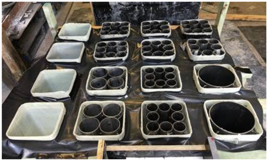
Moulds for casting concrete.
Test set-up and instrumentation
Two pairs of liner variable displacement transducers (LVDTs) were used for each specimen: one pair for measuring the overall axial shortening of the specimen while the other pair for measuring the axial deformation of the 160 mm mid-height region of the specimen, as shown in Figure 4(a). In addition, for each specimen, two axial strain gauges with a gauge length of 10 mm (i.e. gauges S1 and S2 in Figure 4(b)) were attached on the steel tubes. Four lateral strain gauges with a gauge length of 20 mm, including two at the corners (i.e. LC1 and LC2 in Figure 4(b)) and two at the flat sides (i.e. L1 and L2 in Figure 4(b)), were attached at the mid-height of the FRP tube of each specimen.
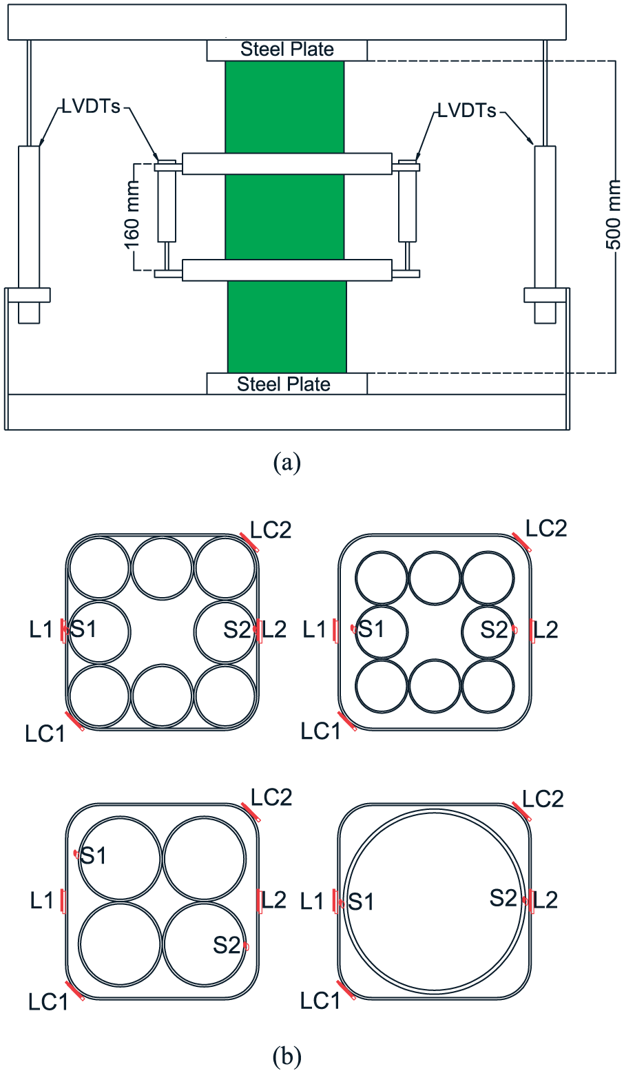
Test set-up: (a) layout of LVDTs and (b) layout of strain gauges.
All compression tests were conducted using a 500-tonne Denison compression test machine with a displacement control rate of 0.6 mm/min. To ensure uniform loading to the end surfaces, a steel cap with gypsum plaster was employed at both the top and bottom ends of a test specimen. All the test data, including strains, loads and displacements, were recorded simultaneously by a data logger.
Experimental results and discussions
General behaviour
During the test, the load kept increasing for all the MTCC and DTCC specimens until hoop rupture of the FRP tube occurred with noticeable noises (Figure 5(a)). The first FRP rupture was generally associated with a significant load drop, but the specimens could still take a large load after it happened. Therefore, it was decided to (1) terminate the test of half of the MTCC and DTCC specimens (i.e. the second specimen of each pair, with an ‘II’ at the end of the name) immediately after the first FRP rupture and (2) keep loading the other half of the MTCC and DTCC specimens (i.e. the first specimen of each pair, with an ‘I’ at the end of the name) until the specimens completely lost their structural integrity (Figure 5(b)). By contrast, all the CFFT specimens lost their structural integrity immediately after the first rupture of the FRP tube (Figure 5(c)); Specimen C-3 with a three-ply FRP tube experienced a small load fluctuation at an axial strain of around 0.003. For the CFFT specimens and DTCC specimens, the FRP rupture generally occurred at or close to one of the corners. However, for some MTCC specimens (i.e. Specimens M8A-3-I, II, M8A-4-I, II and M8B-3-I, II), the FRP rupture occurred in one of the flat sides (i.e. outside and away from the four corners), probably because of local outward bending deformation of the internal steel tubes.
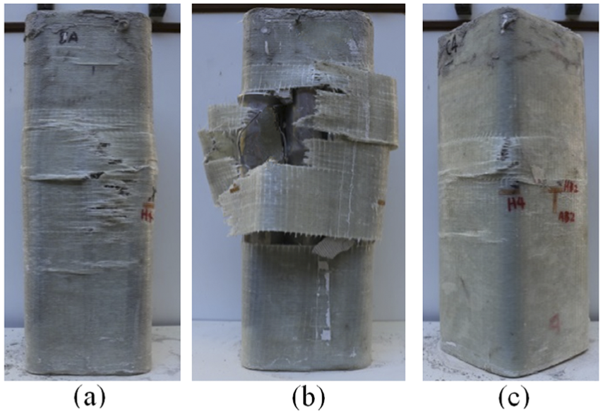
Typical failure modes: (a) Specimen M8A-3-II, (b) Specimen M8A-3-I and (c) Specimen C-3.
All the steel tubes in the MTCC specimens were taken out after test for further examination. Figure 6 shows the steel tubes from typical specimens after test. No significant local buckling or bending deformation was found on the steel tubes from the specimens whose tests were terminated immediately after the first FRP rupture (Figure 6(a)), suggesting that the FRP tube was effective in confining the multiple steel tubes inside an MTCC specimen. By contrast, significantly local buckling and outward bending deformation were noted on the steel tubes after the FRP rupture occurred (see Figure 6(b)).
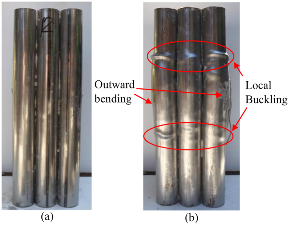
Steel tubes from tested specimens: (a) Specimen M8A-3-II and (b) Specimen M8A-3-I.
Axial load–axial shortening behaviour of MTCC specimens
The axial load–axial shortening curves of the first specimen of each pair are shown in Figure 7, in which the axial shortening was obtained from the average readings of the two LVDTs covering the whole height (i.e. 500 mm) of the specimens. In Figure 7, the points corresponding to the first FRP rupture are denoted by hollow markers of different shapes for different specimens while the final failure when the specimens completely lost their structural integrity is denoted by a cross. It is evident that after the first FRP rupture, the specimens could still take a significant amount of load with a very large axial deformation, although the load drop at the first FRP rupture and the axial shortening corresponding to the final failure both varied significantly among the specimens. For the design of MTCCs, the point at the first FRP rupture may be conservatively taken as the ultimate state, but the energy-absorption capacity of the columns after the first FRP rupture can be an important characteristic for many practical applications. In this article, the ultimate state is defined to be the point at the first FRP rupture; the axial shortening and axial strain at the ultimate state is referred to as the ultimate axial shortening and ultimate axial strain.
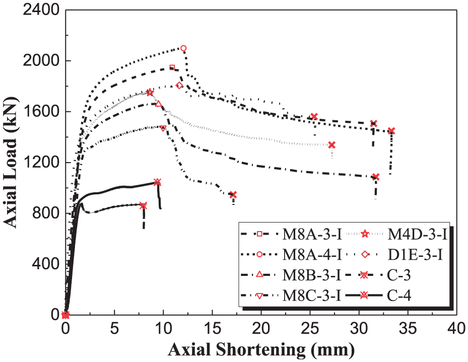
Axial load–axial shortening curves.
Comparison between MTCCs and CFFTs
The axial load–axial strain curves of the MTCC specimens are compared with those of the corresponding CFFT specimens in Figure 8, in which the axial strains were obtained from the average readings of the two LVDTs covering the 160 mm mid-height region. In this article, the axial strains were all obtained in this way unless otherwise specified. In Figure 8, all the experimental curves are terminated at a point corresponding to the first rupture of the FRP tube. The curves of the MTCC specimens are significantly higher than that of the corresponding CFFT specimen because of the existence of additional steel tubes. In addition, two observations can be made from Figure 8: (1) the curves of the MTCC specimens are generally much longer with much larger ultimate axial strains than that of the corresponding CFFT specimen and (2) the second branch of the curves of the MTCC specimens generally has a larger slope than the corresponding CFFT specimen, especially for the specimens with a three-ply FRP tube.
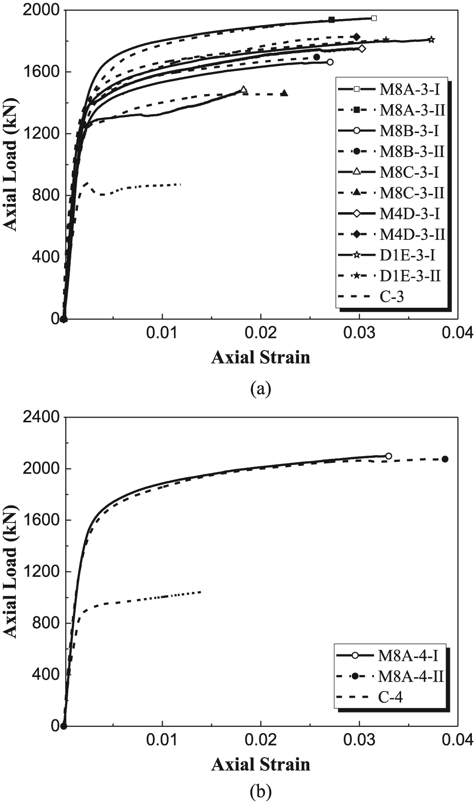
Axial load–axial strain curves: (a) specimens with three-ply of FRP tube and (b) specimens with four-ply FRP tube.
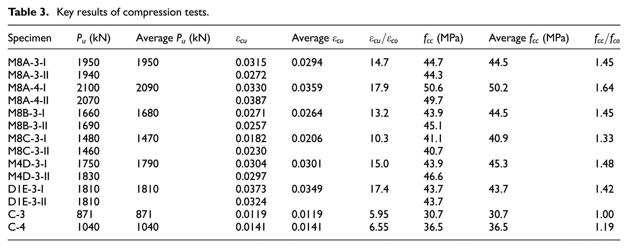
The key results of all the test specimens are summarized in Table 3. In this table, Pu is the ultimate load of the specimen from the test;
Key results of compression tests.
To evaluate the effectiveness of confinement of the concrete in MTCCs, the average stress–strain behaviour of the concrete in the MTCC specimens is compared with that of the corresponding CFFT specimens in Figure 9. The average axial stress of the concrete in the MTCC specimens was obtained by dividing the load carried by the concrete by its cross-sectional area. The load carried by the concrete is assumed to be equal to the difference between the load carried by the MTCC specimen and the load carried by the steel tubes at the same axial strain; the latter was calculated using results from the hollow steel tube tests. When the axial strain of an MTCC specimen exceeds the buckling strain from the corresponding hollow steel tube tests, it is assumed that the load resisted by each of the steel tubes is equal to the peak load from the hollow tube tests, as the buckling of the steel tubes was prevented before the first FRP rupture in the MTCC specimens (Figure 6(a)). The so-obtained ultimate axial stress of confined concrete
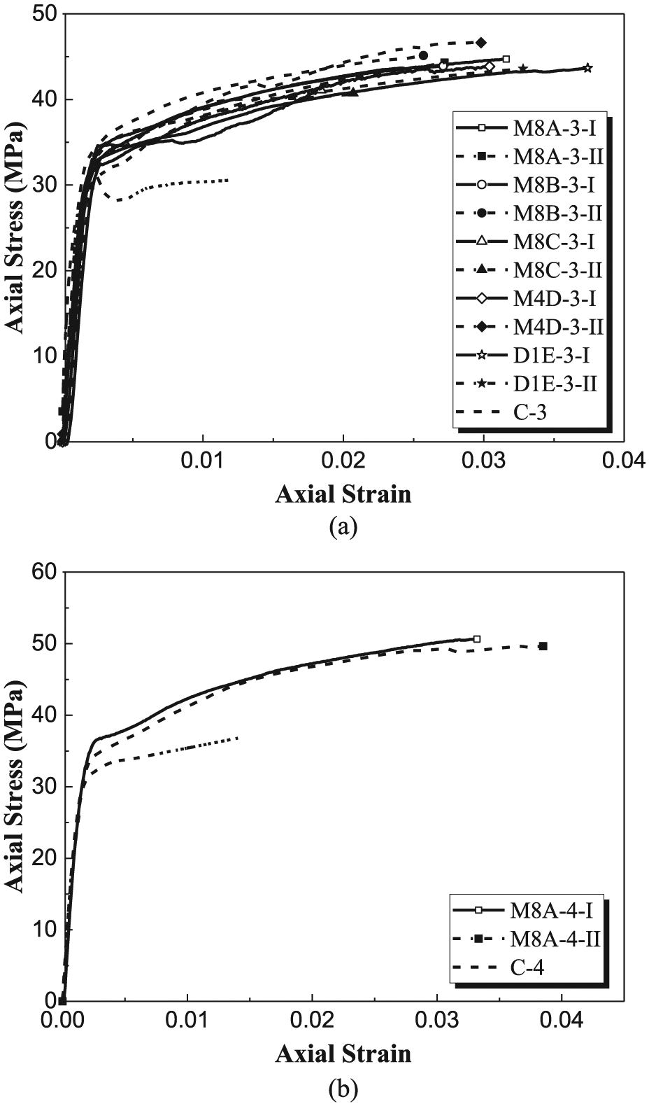
Average axial stress–axial strain curves of concrete: (a) specimens with three-ply FRP tube and (b) specimens with four-ply FRP tube.
Figure 9(a) shows the comparison for all the specimens with a three-ply FRP tube. It is evident that the concrete in the MTCC and DTCC specimens is significantly superior to that in the corresponding CFFT specimen in terms of the compressive strength, ultimate axial strain and the stiffness of the second branch of stress–strain curve. It is also evident that the stress and strain at the transition point between the first and second branches of the curve are both larger for concrete in the MTCC specimens than that in the CFFT specimen. Figure 9(b) shows the comparison for all the specimens with a four-ply FRP tube and similar observations can be made.
Figure 10 compares the axial strain–lateral strain curves of the MTCC specimens and the CFFT specimen with a three-ply FRP tube. The comparison for the specimens with a four-ply FRP tube is similar and is thus not presented here. The lateral strains in Figure 10(a) were averaged from readings of the two strain gauges at the corners (i.e. LC1 and LC2 in Figure 4(b)), while those in Figure 10(b) were averaged from readings of the two strain gauges on the flat sides (i.e. L1 and L2 in Figure 4(b)). It is evident from Figure 10 that at the same axial strain, the lateral expansion of the MTCC specimens was significantly smaller than that of the CFFT specimen, suggesting that the steel tubes in the MTCC specimens were effective in providing additional confinement to the concrete.
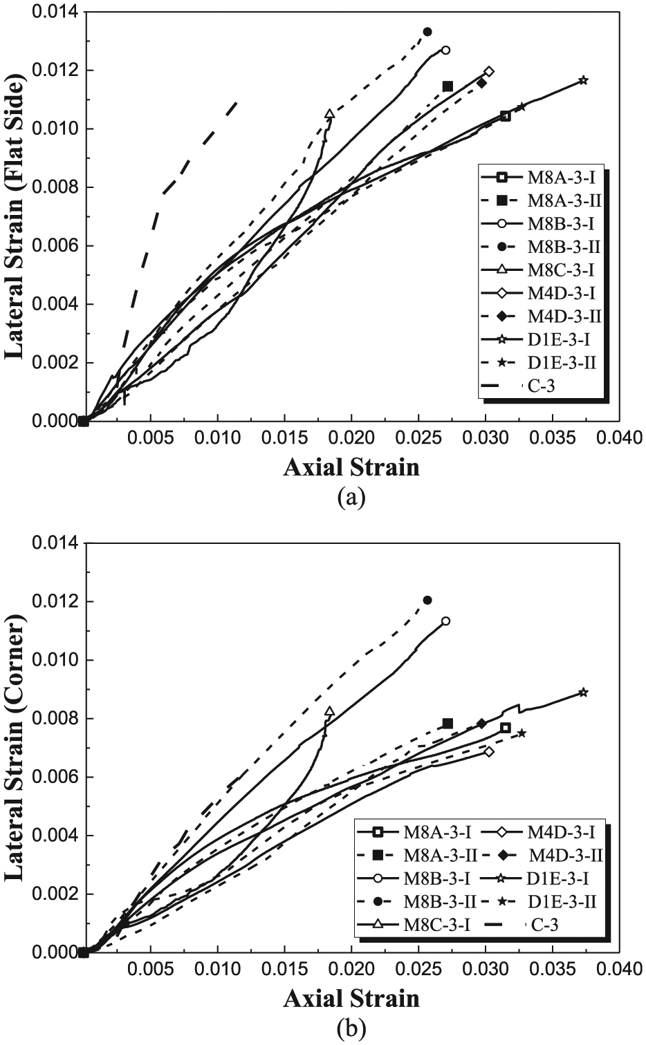
Axial strain–lateral strain curves: (a) lateral strains at the middle of flat sides and (b) lateral strains at the corners.
Effect of thickness of FRP tube
It has been well established that the behaviour of FRP-confined concrete columns depends significantly on the thickness of the FRP tube. A thicker FRP tube generally leads to a larger compressive strength, a larger ultimate axial strain and a stiffer second branch of the stress–strain curve of the confined concrete. The thickness of FRP tube had a similar effect on the MTCC specimens, as evident from Figure 11, which shows a comparison of the average axial stress–axial strain curves of Specimens M8A-3-I, II with a three-ply FRP tube and Specimens M8A-4-I, II with a four-ply FRP tube. The curves of the two corresponding CFFT specimens, namely, Specimens C-3 and C-4, are also plotted in Figure 11 for comparison. It is interesting to note that the curve of Specimen C-3 with a three-ply FRP tube has an approximately flat second branch with some load fluctuations between the first and the second branches, but the curve of Specimens M8A-3-I, II, also with a three-ply FRP tube, has two ascending branches without any load fluctuation. This observation confirms the beneficial effect of the additional confinement from the steel tubes and suggests that for the concrete to be sufficiently confined, the FRP tube in MTCCs can be thinner than that in CFFTs (Lam and Teng, 2003).
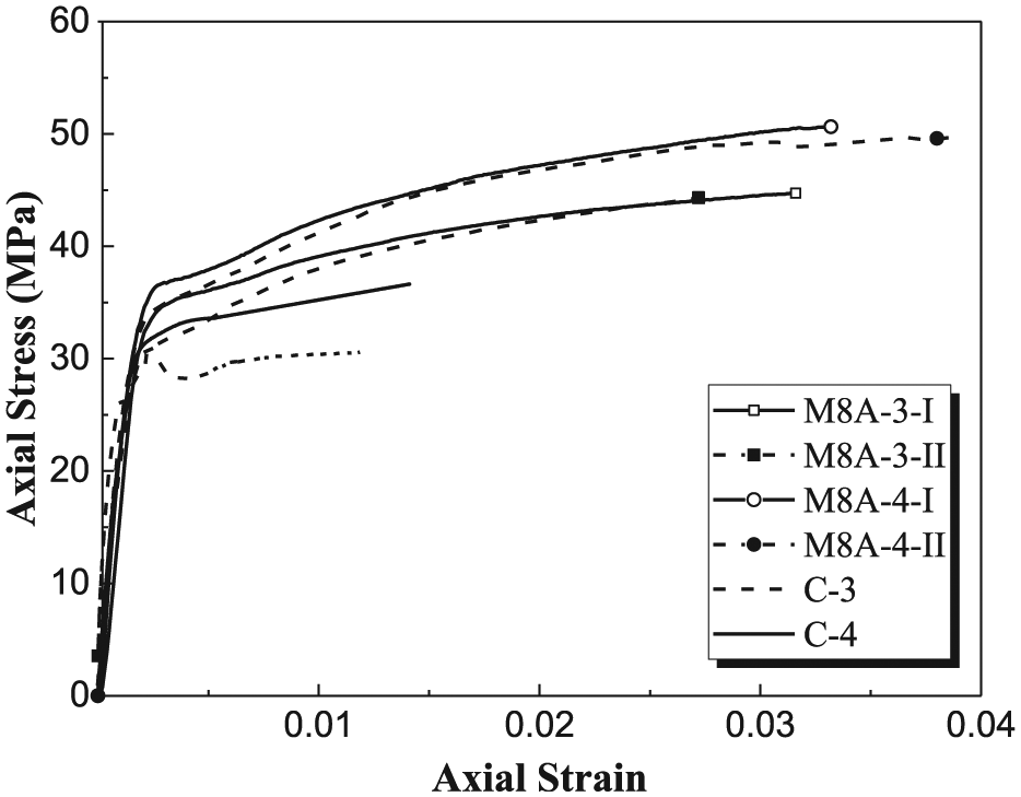
Effect of FRP thickness.
Effect of configuration of steel tubes
Specimens M8C-3-I, II, M4D-3-I, II and D1E-3-I, II had similar volume ratios of steel (Table 1), but different steel tube configurations (i.e. eight tubes, four tubes and one tube, respectively). It is evident from Figure 9(a) that the curves of the three pairs of specimens almost coincide with each other, but the curves of Specimens M8C-3-I, II appear to be much shorter than the others. The shorter curves of Specimens M8C-3-I, II are believed to be due to (1) the relatively thick concrete cover in the two specimens (i.e. 13.5 mm, compared with 3.0 mm in Specimens D1E-3-I, II, as shown in Figure 1) which led to larger lateral expansion at the same axial strain (Figure 10); (2) the relatively low tensile strength of the steel tubes in the two specimens (i.e. 309 MPa compared with 449 MPa in Specimens D1E-3-I, II). The curves of Specimens M8B-3-I, II may be used to further examine this issue. Compared with Specimens M4D-3-I, II and D1E-3-I, II, the steel volume ratio of Specimens M8B-3-I, II was slightly larger (i.e. 13% larger than Specimens M4D-3-I, II and 18% larger than Specimens D1E-3-I, II), but the tensile strength of the steel tubes in the two specimens was lower (i.e. 16% lower than Specimens M4D-3-I, II and 41% lower than Specimens D1E-3-I, II) (Tables 1 and 2). Figure 9(a) shows that the difference between the curves of Specimens M8B-3-I, II and those of Specimens D1E-3-I, II and M4D-3-I, II are minor, suggesting that the steel configuration, within the range tested in the present study, has a minor effect on the behaviour of MTCCs.
Effect of dimensions of steel tubes
The effect of dimensions of steel tubes can be examined by comparing the average stress–strain curves of concrete in Specimens M8A-3-I, II, M8B-3-I, II and M8C-3-I, II. Figure 9(a) shows that the three pairs of curves generally agree well with each other, but terminate at different ultimate axial strains. The ultimate axial strain appears to increase with the volume ratio of the steel tubes; Specimens M8C-3-I, II had the smallest ultimate axial strains among the three pairs of specimens. As discussed above, besides their relatively small volume ratio of steel, the relatively thick concrete cover in Specimens M8C-3-I, II may also attribute to their relatively small ultimate axial strains. Further research is needed to clarify this issue.
Modelling of axial load–axial strain behaviour
General
In this section, a simple analytical model is presented for the estimation of axial load–axial strain curves of square MTCCs. In general, the cross-section of a square MTCC is divided into two parts: (1) the steel tubes and the concrete inside the steel tubes and (2) the rest of the concrete. The proposed model involves certain assumptions to simplify the problem, so it may not reflect the complex mechanism of square MTCCs. Nevertheless, it provides reasonable predictions and can be used for the conservative design of MTCCs before a more rational design approach is developed, as shown later in this section.
Proposed model
The assumptions adopted in the present model include (1) the axial load–axial strain behaviour of the CFSTs in square MTCCs is the same as that of CFSTs loaded alone and can thus be predicted by existing models for CFSTs; (2) the axial load–axial strain behaviour of the rest of the concrete is the same as that of concrete in a CFFT with the same FRP tube and can thus be predicted by existing models for square CFFTs; (3) the concrete and the steel tubes are always subject to the same axial strain and (4) the ultimate axial strain of MTCCs is the same as the CFFT with the same FRP tube and concrete.
In the proposed model, the analysis-oriented model proposed by Teng et al. (2013) was adopted for the CFSTs, while the design-oriented model proposed by Lam and Teng (2003) was adopted for the concrete outside the steel tubes in MTCCs. Lam and Teng (2003) suggest that the nominal hoop rupture strain of FRP in the equivalent circular column should be used in their model. In the present study, the nominal FRP rupture strain is taken to be 0.02. Readers may refer to Teng et al. (2013) and Lam and Teng (2003) for more details of the models.
Comparison with test results
The comparisons between the predictions of the proposed model and the test results are shown in Figure 12. In making the predictions, the nominal hoop rupture strain of the FRP jacket in the equivalent circular column of 0.02 was adopted to compute the ultimate axial strain of the part (2) of the concrete section. It is evident from Figure 12 that the predicted curves are close to the experimental curves, except that the former generally terminate early at a much smaller ultimate axial strain. As a consequence, the model slightly underestimates the ultimate load. The model may thus be used for conservative design of square MTCCs.
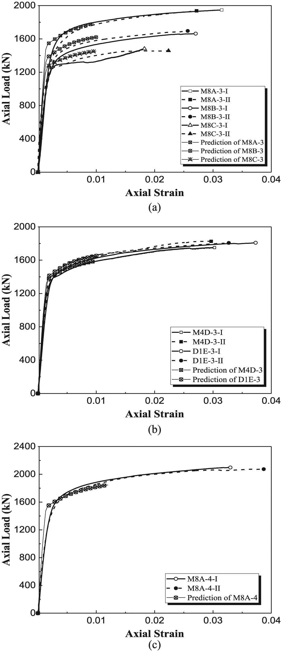
Comparison between test results and predictions of proposed model: (a) Specimens M8A-3-I, II, M8B-3-I, II and M8C-3-I, II; (b) Specimens M4D-3-I, II and D1E-3-I, II and (c) Specimens M8A-4-I, II.
Conclusion
This article has presented results from a series of axial compression tests on square MTCCs and two similar column forms: CFFTs and DTCCs. The test variables included the thickness of the external FRP tube, and the dimensions and configuration of the internal steel tubes. Based on the test results and discussions presented in the article, the following conclusions can be drawn:
The concrete in the tested MTCCs was very effectively confined despite the square shape of the columns, and the local and overall buckling of the steel tubes in the tested MTCCs was completely prevented, leading to excellent performance of the columns.
Compared with the concrete in the square CFFT specimen with the same FRP tube, the concrete in the square MTCC specimens had significantly superior behaviour, in terms of the compressive strength, the ultimate axial strain and the stiffness of the second branch of the stress–strain curve.
The MTCC specimens could still take a significant amount of load with a large axial deformation after the first rupture of the FRP tube.
A simple analytical model has also been presented for the prediction of the axial load–axial strain behaviour of MTCCs. A comparison with the test results shows that the proposed model can provide reasonable predictions and may be used for the conservative design of MTCCs. Future research involving the development of sophisticated finite element models needs to be conducted to investigate the complex stress distributions in the columns and the buckling behaviour of the internal steel tubes, before a more rational design approach can be established.
Footnotes
Acknowledgements
The authors also wish to thank Miss Dinithi Tharaka Fernando and Mr Hong Khanh Vu for their valuable contribution to the experimental work.
Declaration of Conflicting Interests
The author(s) declared no potential conflicts of interest with respect to the research, authorship and/or publication of this article.
Funding
The author(s) disclosed receipt of the following financial support for the research, authorship, and/or publication of this article: the author recieved financial support by the Australian Government through the Australian Research Council’s Discovery Projects funding scheme (project ID: DP170102992)