





Abstract
In this article, the dynamic analysis of three-dimensional high-speed train-track model is carried out using moving element method. The train comprises a car-body supported by a secondary suspension system to a bogie. The bogie is in turn connected to wheel-sets through a primary suspension system. A total of 16 degrees of freedom is employed to describe the vertical, lateral, rolling, pitching, and yawing displacements of the car-body, the bogie, and the wheel-sets. The Hertzian contact and Kalker’s linear theory are used to account for the vertical and lateral contact forces between the wheels and rails. Two rails are modeled as two Euler–Bernoulli beams resting on a viscoelastic foundation. The moving element method is extended to establish the coupling formulations of the mass, damping, and stiffness matrices in vertical and lateral directions, where the element matrices are formulated based on a convected coordinate system attached to the moving vehicle. The dynamic amplification factor is defined as the ratio of the maximum dynamic contact force to the static load at the contact point between the wheel and the rail. To illustrate the benefits of the proposed three-dimensional train-track model, several numerical examples are performed in this study to present the effects of the train speed, the resonance phenomenon, the track irregularity, and track stiffness variations along the track and across the track width on the dynamic amplification factor of the high-speed train.
Keywords
Introduction
In recent decades, the development of high-speed rail (HSR) has gained an important role in travel due to their efficiency and environmentally friendly technologies. This has led to the increasing of train speed, higher axle load, and more frequent train usage. However, these improved train technologies have brought new challenges in solving the dynamic interaction problems of the train-track. A number of studies have been conducted to study the problems of train-track dynamic interaction. The HSR system has been investigated as a rail beam resting on a viscoelastic foundation subjected to moving loads. By means of Fourier transform method (FTM) and a moving coordinate system, Mathews (1958, 1959) solved the dynamic problem of a moving load along an infinitely long beam resting on an elastic foundation. Jezequel (1981) studied the dynamic problem of an Euler–Bernoulli infinite beam resting on elastic supports subjected to a concentrated force moving at constant speed. Similar works using the FTM were carried out by Ono and Yamada (1989), Sun (2002), and Chen and Wang (2006). The FTM may give accurate solutions but it is cumbersome when dealing with complicated coupled systems, such as multi-degrees of freedom (DOFs) system with multiple contact points.
In practice, the finite element method (FEM) has also been widely employed in the moving load problems. Filho (1978), Hino et al. (1984, 1985), and Olsson (1985) are the pioneers in the development of finite element formulations for analyzing structures subjected to moving loads. They presented a review on the use of the FEM for solving the problems of a uniform beam subjected to moving loads. Frýba et al. (1993) presented a stochastic finite element for a beam resting on a random foundation with uncertain damping under moving force. Thambiratnam and Zhuge (1993, 1996) proposed a finite element model for simply-supported beams resting on an elastic foundation subjected to moving loads and applied to the analysis of track structures subjected to point or uniformly distributed loads. Nielsen and Igeland (1995) solved the problem of a beam resting on sleepers and treated a bogie as a moving load. A complex modal superposition technique was employed to study the effects of corrugated rail, wheel-flat, and unsupported sleepers.
In dealing with moving load problems, the FEM encounters difficulties when the moving load approaches the boundary of the finite domain and travels beyond the boundary. These difficulties can be overcome by employing a large enough domain size but the computational cost will increase significantly. To deal with the complication encountered by the FEM, Krenk et al. (1999) proposed the use of convected coordinate in the FEM to analyze the response of an elastic half-space subjected to a moving load. The benefit of this approach is its ability to overcome the problem due to the moving load traveling over a finite domain. On the same thread, Andersen et al. (2001) presented a FEM study of a beam on a Kelvin foundation subjected to a harmonic moving load. Koh et al. (2003) adopted the idea of convected coordinate for solving train-track problems and named the numerical algorithm as moving element method (MEM). The method was subsequently applied in the analysis of in-plane dynamic responses of annular disk (Koh et al., 2006) and moving load on continuum (Koh et al., 2007). Xu et al. (2009) extended the one-dimensional MEM proposed by Koh et al. (2003) to two-dimensional (2D) problems for investigating the dynamic responses of an infinite Kirchhoff plate resting on a Kelvin foundation subjected to a moving vehicle. Recently, Ang and Dai (2013) employed the MEM to investigate the dynamic response of high-speed train-track system for the situation where there is an abrupt change of foundation stiffness. The influence of different factors, including the degree of change of foundation stiffness, traveling velocity of train, and the severity of track irregularity, on the response of the train as well as the track is examined and discussed. Ang et al. (2014) applied the MEM to investigate the “jumping wheel” phenomenon in high-speed train motion at constant velocity over a transition region where there is a sudden change of the foundation stiffness. Tran et al. (2014) analyzed the dynamic response of high-speed train traveling at non-uniform speed using the MEM. In this study, both linear and nonlinear wheel-rail contact models were examined. Dai and Ang (2015) presented an analytical solution for the steady-state response of a curved beam resting on a viscously damped foundation and subjected to a single or sequence of moving loads using MEM. On the same thread, Tran et al. (2016, 2017a, 2017b) employed the MEM to investigate the dynamic response of high-speed train-track system experiencing heavy braking and abrupt braking. Most recently, Tran et al. (2017c) examined the vertical dynamic response of HSRs during sudden deceleration using the MEM. The effects of the wheel sliding, initial train deceleration, initial train speed, and the severity of the railhead roughness on the dynamic response of the HSR were investigated. Dai et al. (2017) proposed a computational scheme in conjunction with the MEM to investigate the dynamic response of a high-speed train-track system in which the discrete sleepers on the sub-grade support the railway track.
Many previous studies have proposed the use of simple 2D train-track models, in which the train has been modeled by 3-DOF or 10-DOF system and only one side of the track is used for calculation. The disadvantages of the 2D train-track models are that these models can be employed to examine the effects of track irregularity and track stiffness variations along the track on the dynamic response of high-speed train only. But the effects of track irregularity and track stiffness variations across the track width (one rail related to the other rail) on the dynamic response of high- speed train cannot be captured using them. This article is hence proposed to fill in the above-mentioned research gap by extending the application of MEM to investigate the full dynamic interaction of the high-speed train-track system with the complex three-dimensional (3D) train-track model. In the proposed model, the train is modeled by 16 DOFs involving vertical, lateral, rolling, pitching, and yawing displacements of the car-body, the bogie, and the wheel-sets. Two rails are modeled as two Euler–Bernoulli beams resting on a viscoelastic foundation. The benefits of the proposed model compared to previous 2D train-track models are that all of motions of the train components and the effects of track irregularity and track stiffness variations across the track width can be captured for calculating the dynamic response of the high-speed train. To achieve the above-mentioned purpose, the Hertzian contact and Kalker’s linear theory are employed to account for the vertical and the lateral contact forces between the wheels and the rails. The coupling formulations for calculating the mass, damping, and stiffness matrices in both vertical and lateral directions of the moving elements are presented. The dynamic amplification factor (DAF) is defined as the ratio of the maximum dynamic contact force to the static load at the contact point between the wheel and the rail. To illustrate the advantages of the proposed 3D train-track model, several numerical examples are performed in this study to present the effects of train speed, resonance phenomenon, track irregularity, and track stiffness variations along the track and across the track width on the DAF of the high-speed train.
Formulation
3D train model
Figure 1 shows the 3D train model including three different views (longitudinal, transverse, and plane). The train model comprises a car-body supported through a secondary suspension system to a bogie. The bogie is in turn connected to two wheel-sets through a primary suspension system. Both suspension systems are modeled with an appropriate number of vertical and horizontal spring-damping units. The pitching and yawing motions of the car-body are neglected due to the fact that the pairs of front and rear wheel-sets supporting the car-body are spaced far apart in a typical high-speed train coach.
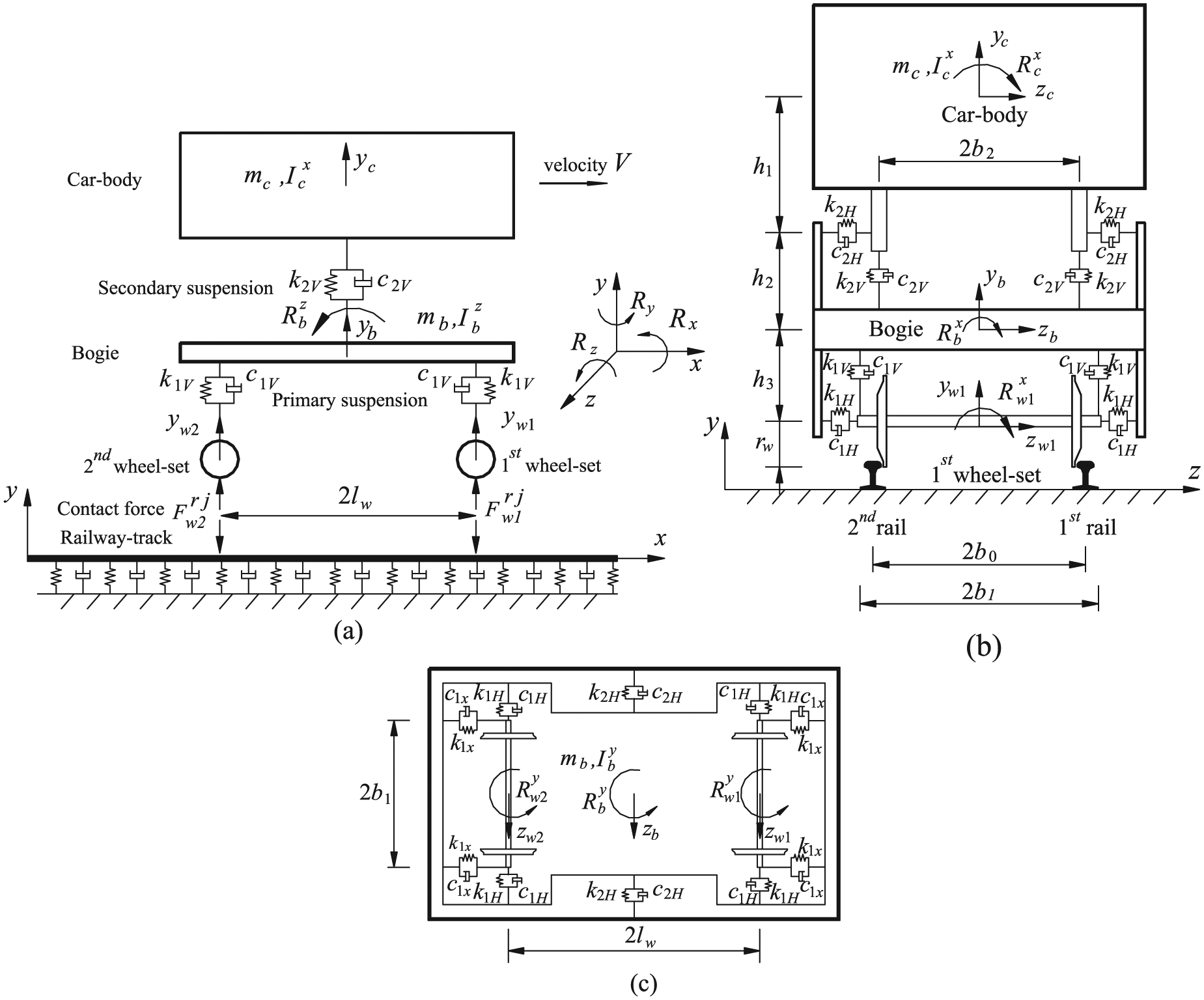
3D train model: (a) longitudinal view, (b) transverse view, and (c) plane view.
A total of 16-DOF system is employed to describe the motions of various components of the train. The displacement vector for the 3D train model can be written as

where
The equation of motion of the train can be written in the general form as

in which
The mass matrix of the train is expressed as

where



in which
The stiffness matrix of the train is symmetric and can be established as
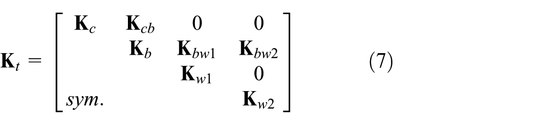
where



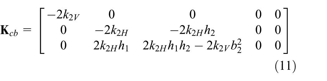
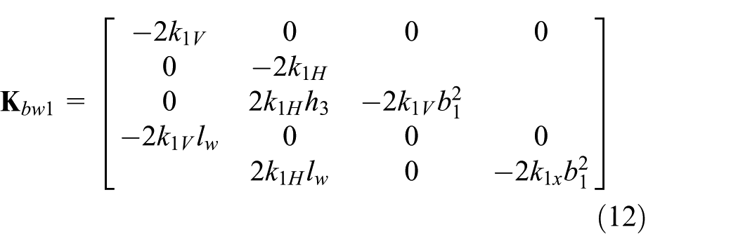
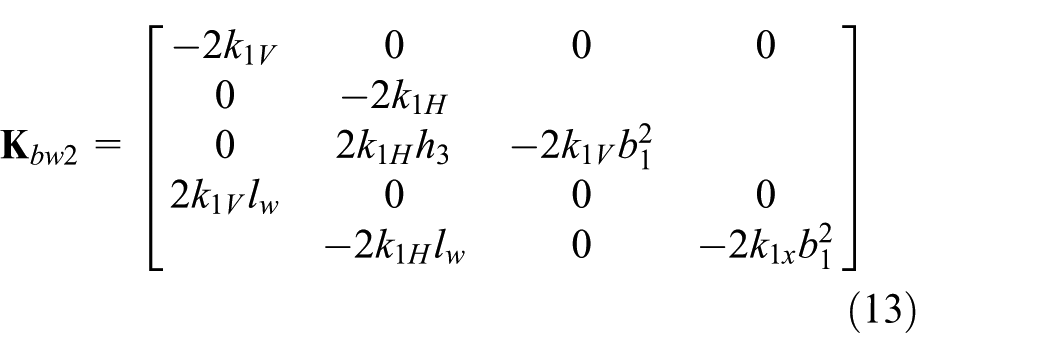
in which
The damping matrix of the train is symmetric and can be written as
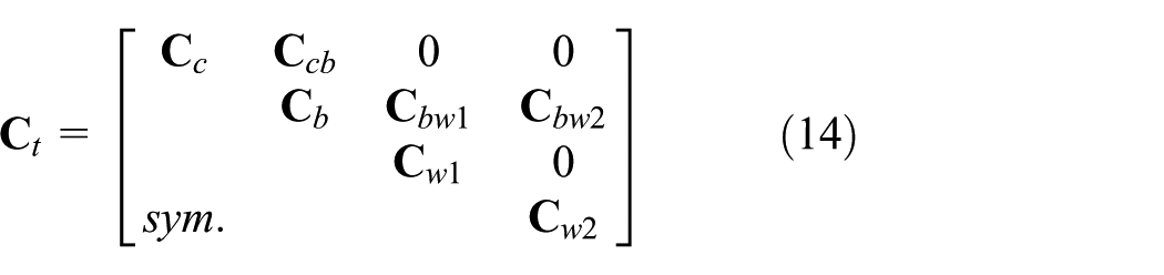
where the sub-damping matrices have the same forms as the sub-stiffness matrices and can be obtained by replacing the stiffness coefficient “k” everywhere by the damping coefficient “c”.
The force vector

where



in which
Wheel-rail contact model
The wheel-rail contact model is shown in Figure 2(a). The Hertzian contact is employed to account for the vertical contact force

where

in which
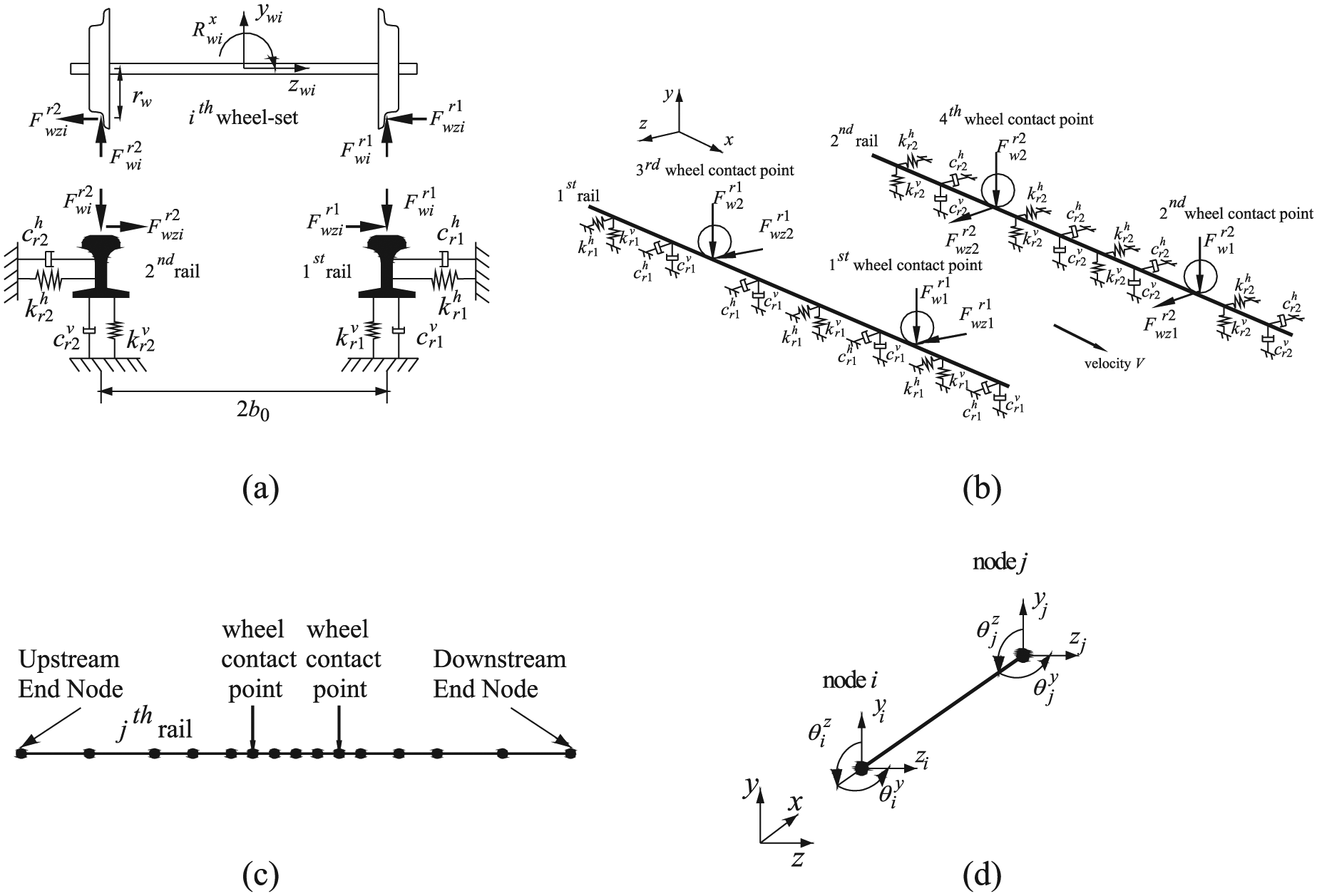
(a) Wheel-rail contact model; (b) 3D track model; (c) discretization of one typical rail beam into moving elements; and (d) typical frame element with 8 DOFs.
The indentation at the contact force

in which
The track irregularity is a main factor of the dynamic excitation force acting on the train-track system, and it describes the vertical unevenness in the railhead surface which arises due to various factors such as wear, tear, and plastic deformation. The track irregularity profile is widely assumed to take the sinusoidal form as proposed by Nielsen and Abrahamsson (1992) and it is written as follows

where
When the train travels far away from its initial position, the exponential term in equation (22) will soon become negligible (Ang et al., 2014); thus, for simplicity, the expression for the vertical track irregularity profile can be written in terms of a sinusoidal function as

The Kalker’s linear theory is employed to account for horizontal contact force

where


in which
3D track model
The 3D track model is shown in Figure 2(b), in which two rails are assumed as two infinite Euler–Bernoulli beams resting on a viscoelastic foundation subjected to moving vertical and lateral contact forces.
The governing equations of vertical and lateral motions of the
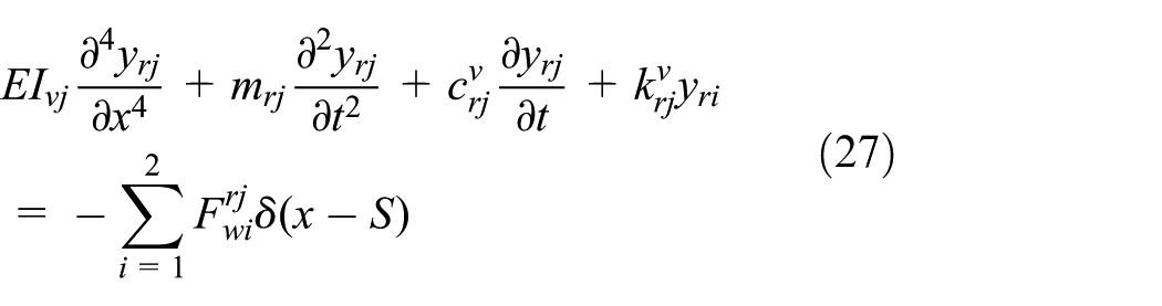
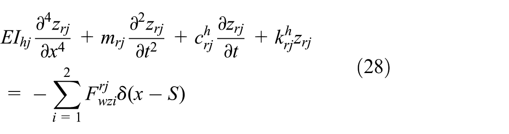
where t denotes the time; S is the distance traveled by the train at any instant time t;
Figure 2(c) shows the discretization of one typical rail beam into a finite number of moving elements (as proposed by Koh et al., 2003; the length of the rail beam elements are not necessarily equal). Both the upstream and downstream ends of the beam are taken to be sufficiently far from the contact forces such that their end forces and moments are zero. The typical frame element with 8 DOFs is shown in Figure 2(d). The nodal displacement vector for the frame element can be written as follows

By using the interpolation functions, the vertical and lateral displacements in the rail element can be expressed as

in which


where
MEM
The MEM is proposed with the idea of attaching the origin of the spatial coordinate system to the applied point of the moving load (Koh et al., 2003). The relationship between the moving coordinate r and the fixed coordinate x is given by

In view of equation (33), the governing equations (27) and (28) may be written as
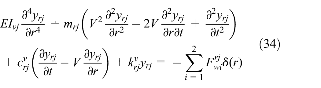
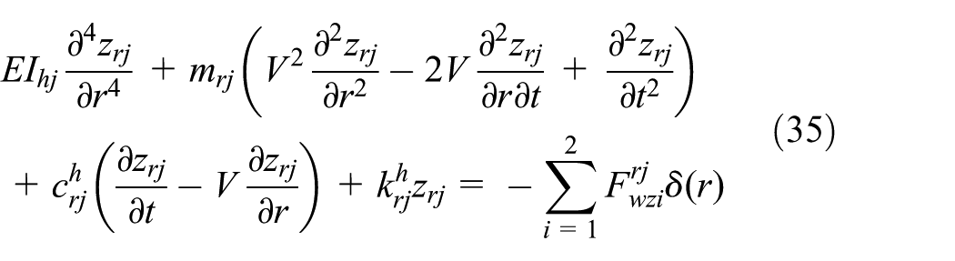
By adopting Galerkin’s approach and procedure of establishing the weak form in terms of the displacement field, the formulations for the mass, damping, and stiffness matrices of the moving element of the

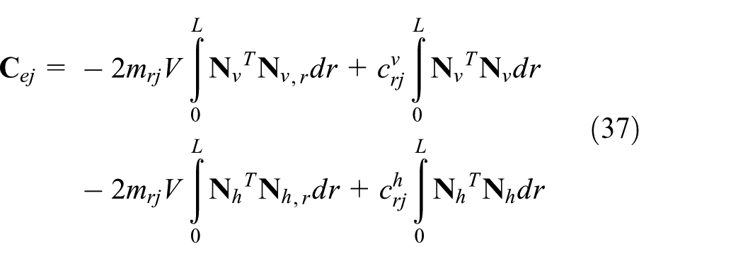
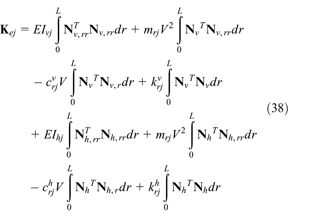
where
After assemblage, the equation of motion for the 3D train-track model can be written as

where
Numerical results
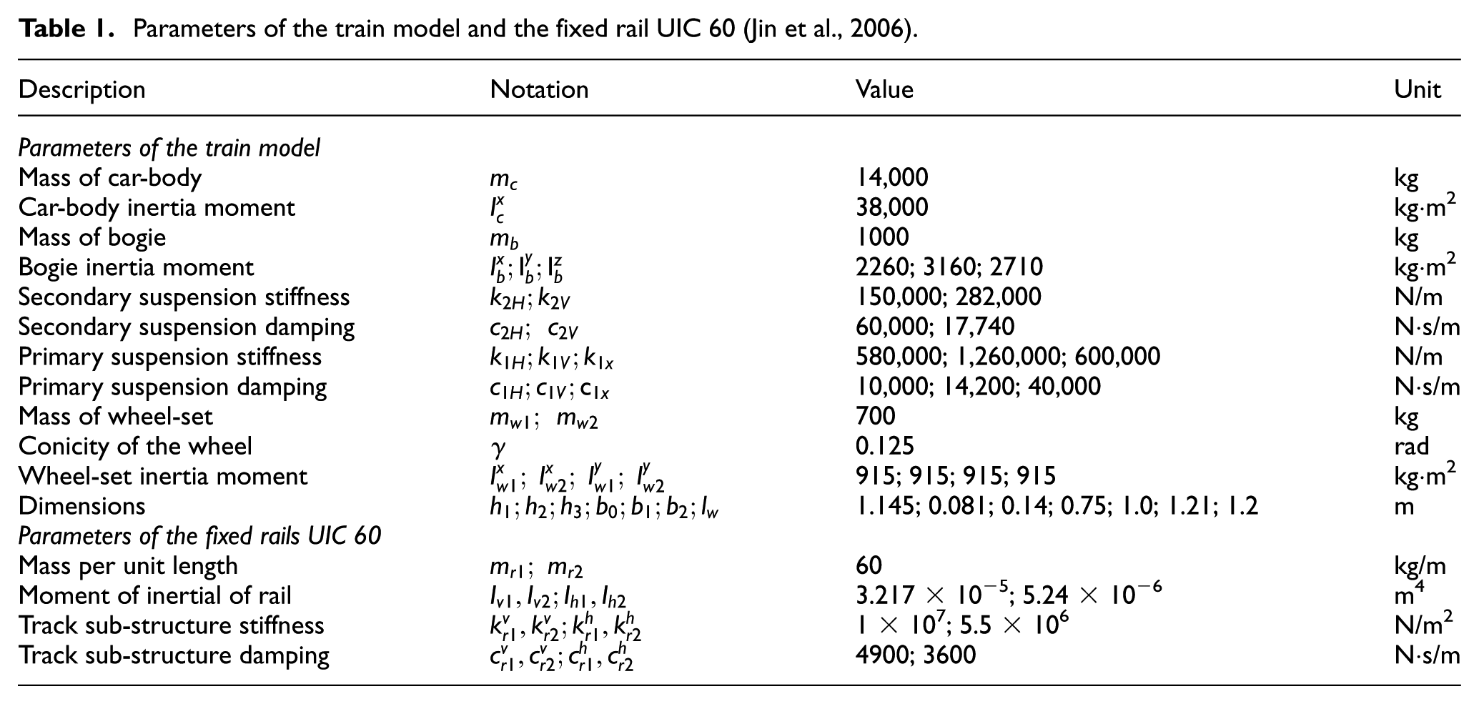
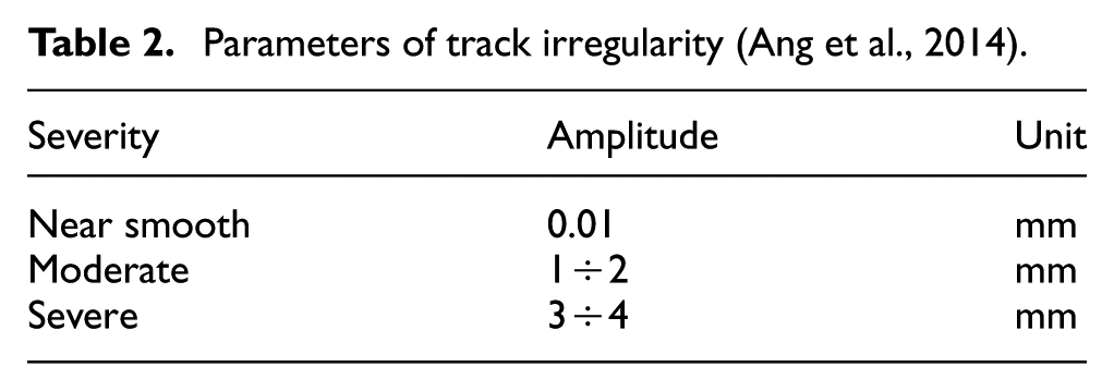
To verify the accuracy of the proposed 3D train-track model and the MEM approach, the results of this study are compared with the results obtained by Koh et al. (2003). The parameters related to the properties of the high-speed train-track system are summarized in Tables 1 and 2.
Parameters of the train model and the fixed rail UIC 60 (Jin et al., 2006).
Parameters of track irregularity (Ang et al., 2014).
For the purpose of comparison, the train speed
One advantage of the MEM is that it allows the use of variable element lengths for better computational efficiency. Figure 3 shows the non-uniform discretization of the rail beams with a total of
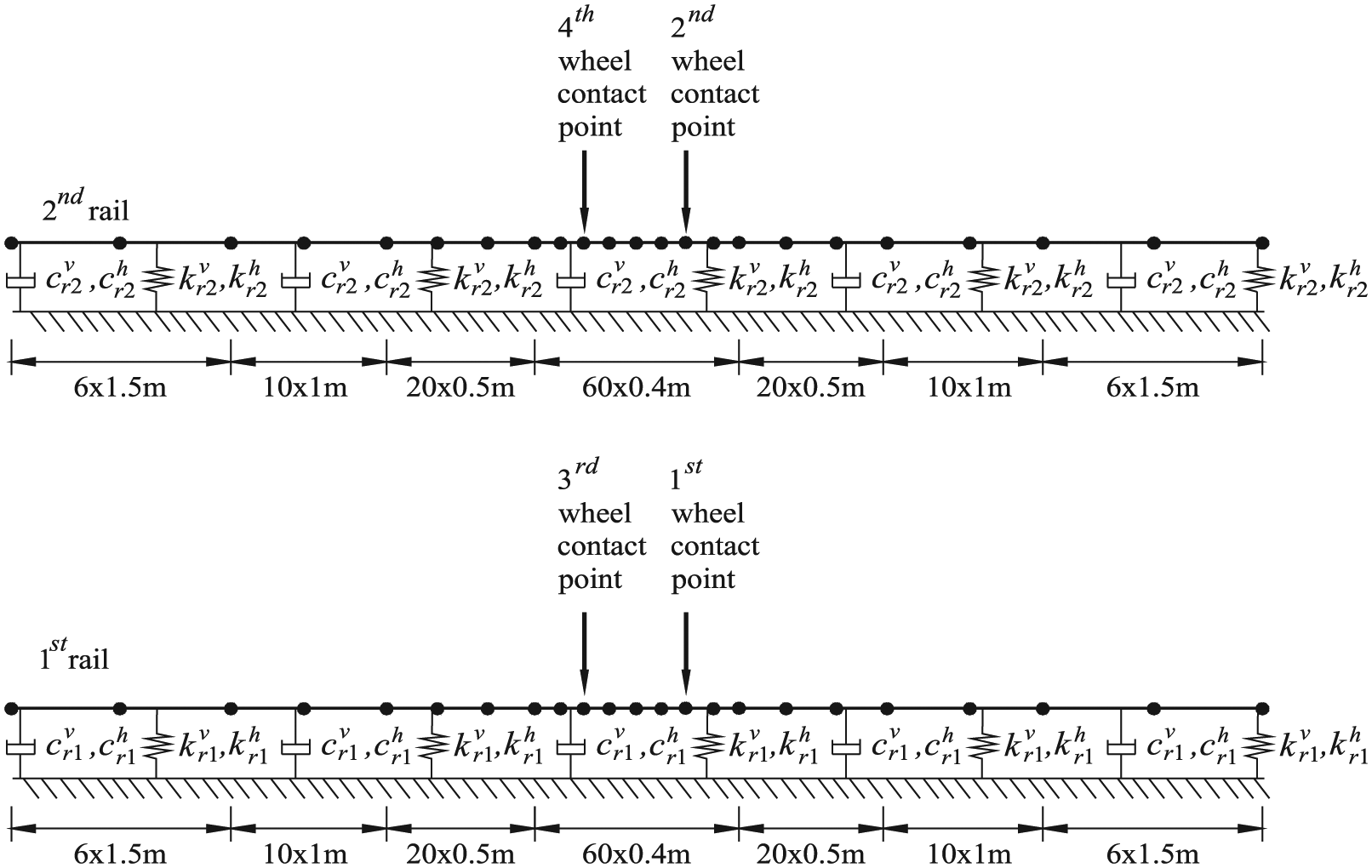
Discretization of two rail beams into moving elements used in this model.
Figure 4 shows the time history displacements of the rails at four contact points for steady-state condition. The rails are assumed to be smooth in this case (
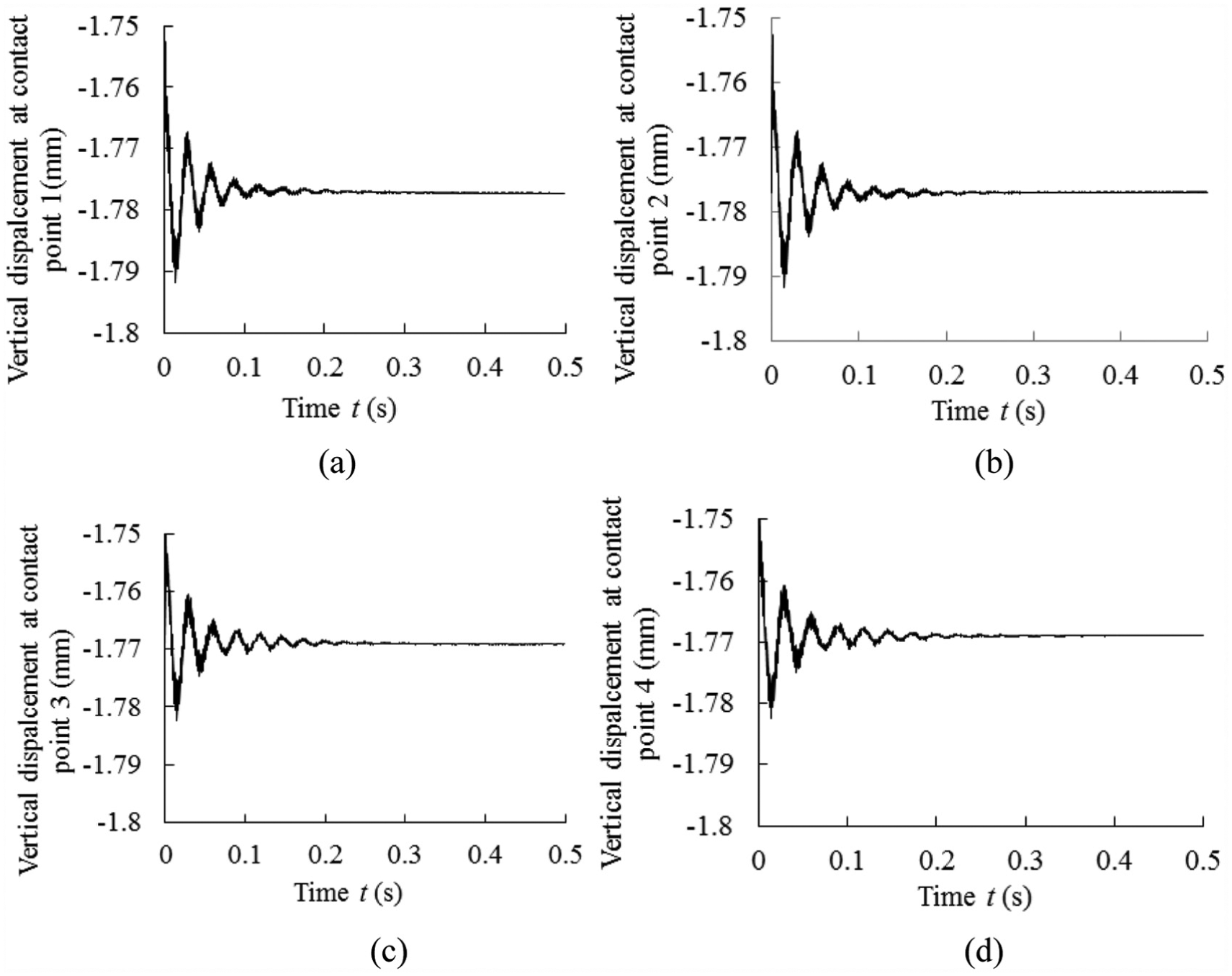
Time history displacements of the rails at four contact points for steady-state condition (track irregularity amplitude
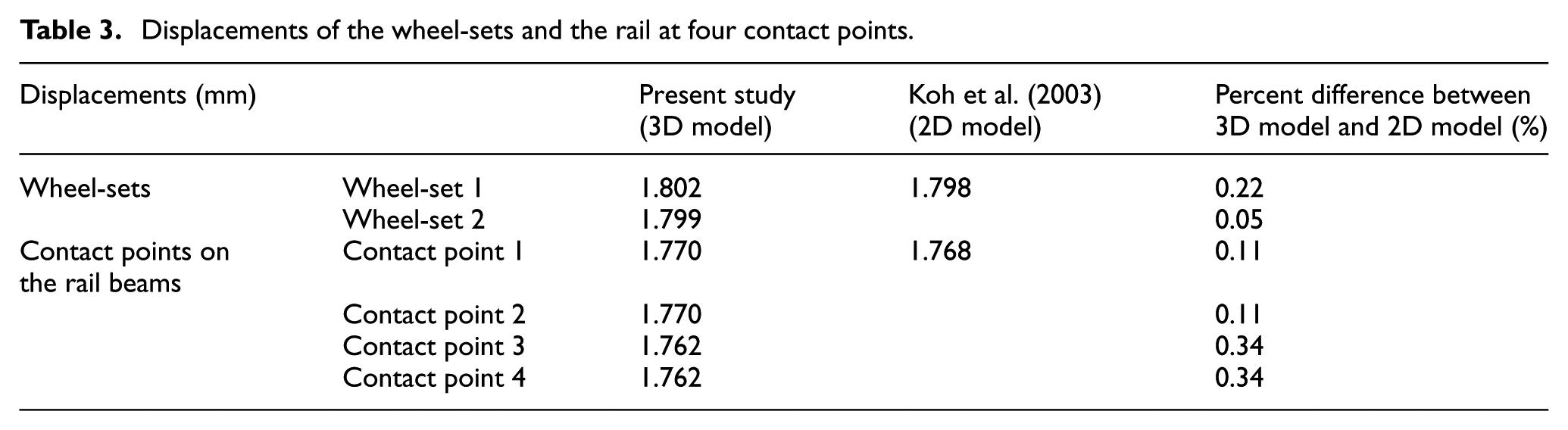
Table 3 shows the displacements of the wheel-sets and the displacements of the rail at four contact points when the amplitudes and wavelengths of track irregularity are
Displacements of the wheel-sets and the rail at four contact points.
The DAF is defined as the ratio of the maximum dynamic contact force to the static wheel load, which is the sum of the self-weight of car-body, bogie, and wheel-sets. As expected, for the case of perfectly smooth track and no dynamic load, the DAF is found to be 1. When the DAF is greater than or equal to 2, there is the momentary loss of contact between the wheel and rail, which is known as the jumping wheel phenomenon (Ang et al., 2014). First, the effects of the track irregularity amplitude on DAF1, DAF2, DAF3, and DAF4 at four contact points are shown in Figure 5. In this example, the track irregularity amplitudes of two rails are the same
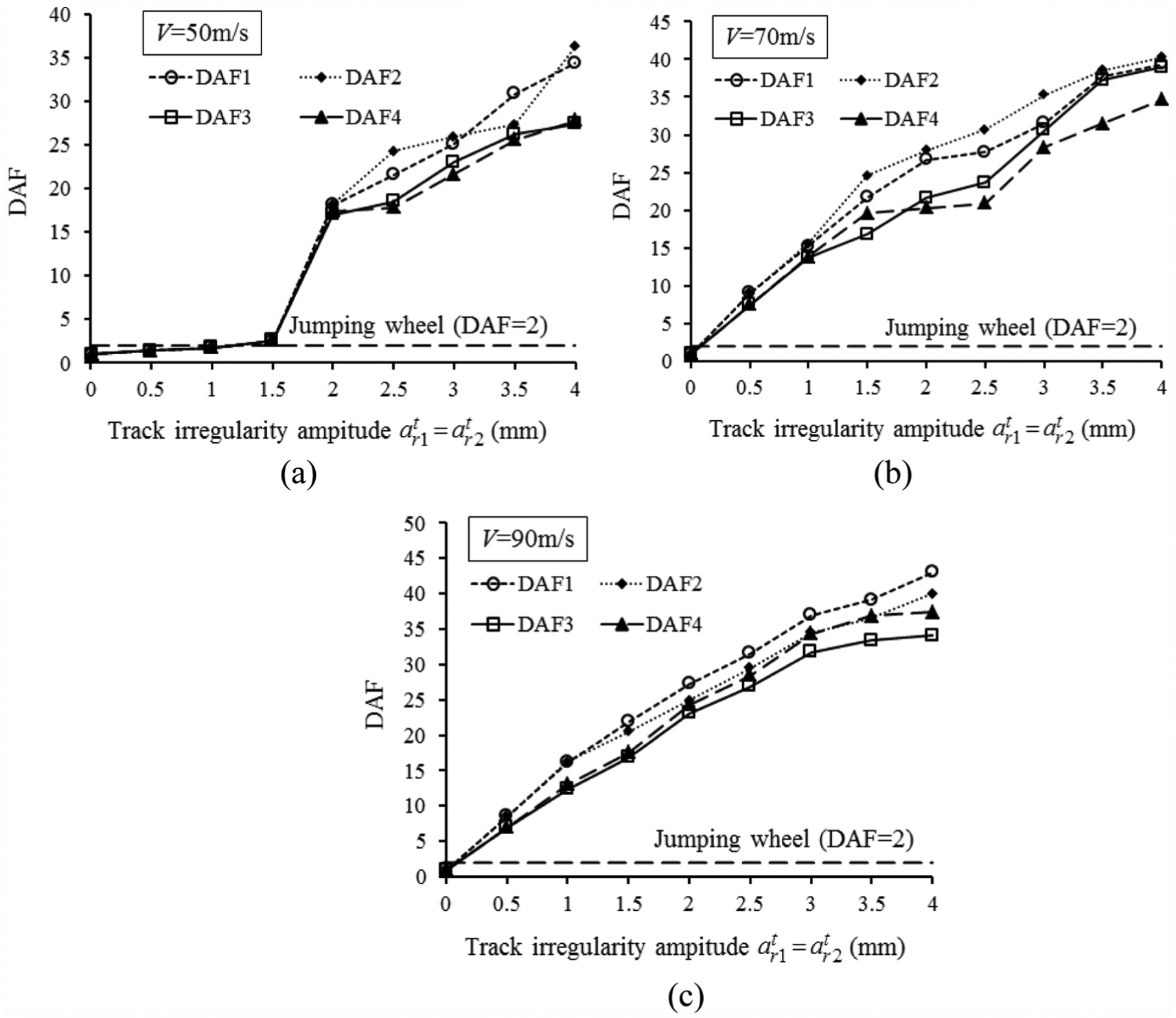
Effect of track irregularity amplitude on the DAF. The train speed of (a)
Second, the effects of the track irregularity amplitude ratio
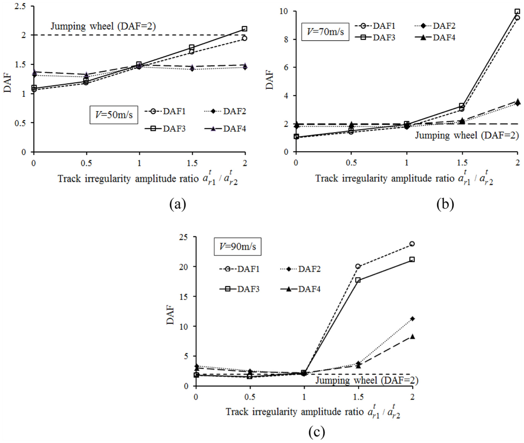
Effect of the track irregularity amplitude ratio
Third, the effects of the track irregularity wavelength on the DAF are investigated. The track irregularity amplitudes of two rails are
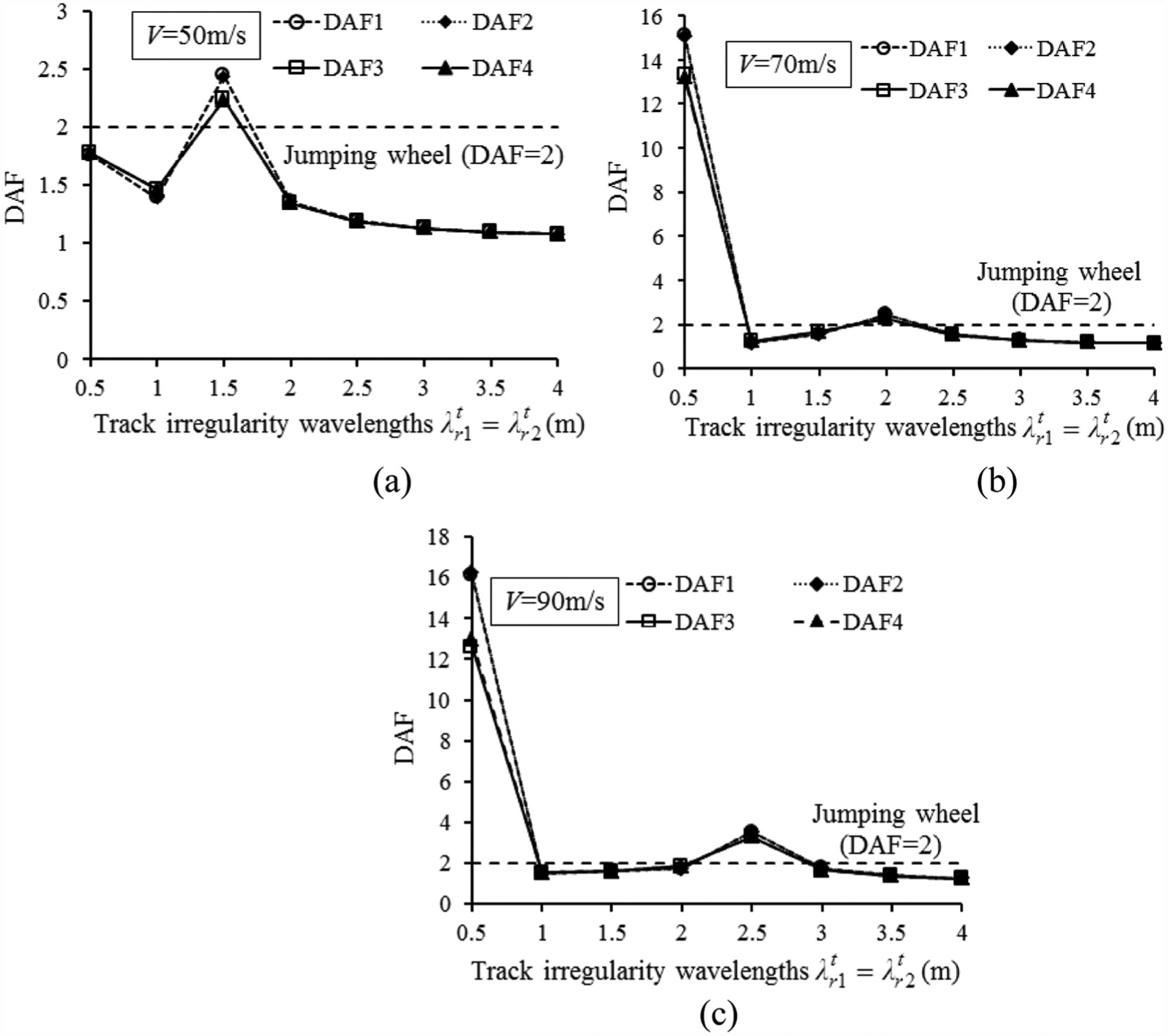
Effect of track irregularity wavelength on the DAF. The train speed of (a)
The resonance phenomenon occurs when the frequency of the dynamic excitation force approaches the natural frequencies of the components of the train. The frequency

The natural frequency

in which

Table 4 shows the numerical results of frequencies of the dynamic excitation forces for the irregularity wavelengths ranging from 0.5 to 4 m and the train speeds of
Frequency
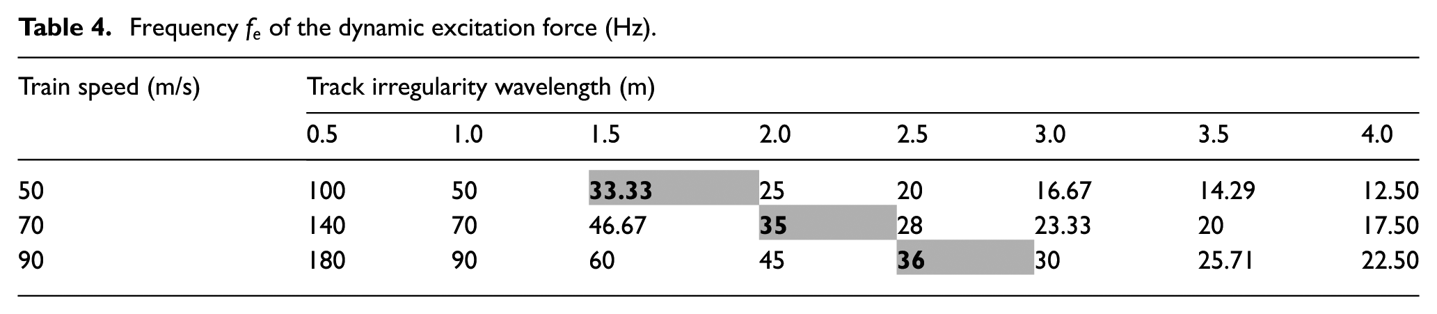
Natural frequencies

Figure 8 shows the effects of the track irregularity wavelength ratio
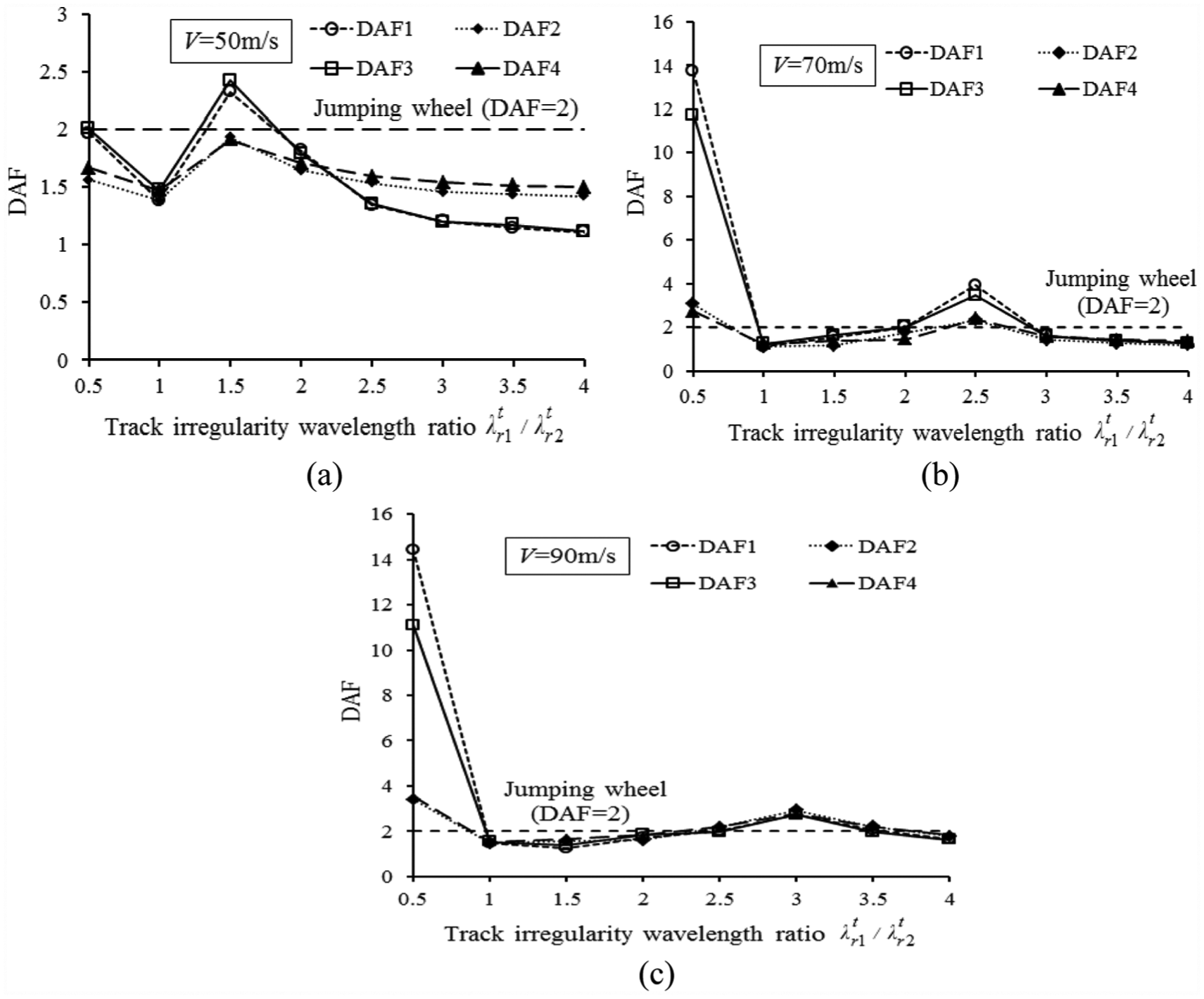
Effect of the track irregularity wavelength ratio
The effects of the track sub-structure stiffness on the DAF are next investigated. The track irregularity amplitudes and wavelengths of two rails are
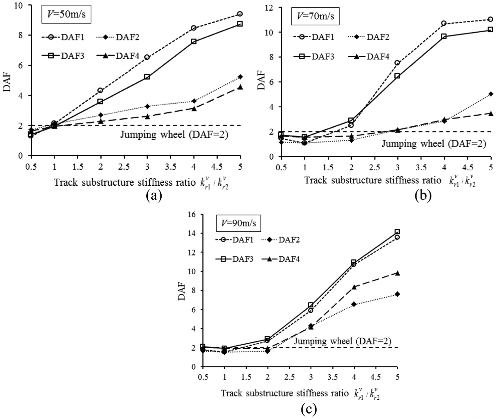
Effect of the track sub-structure stiffness ratio
Conclusion
In this article, a numerical study on the dynamic response of the 3D train-track model using MEM was carried out. The train was modeled as a complex 3D train model with 16 DOFs, and the two rails were modeled as two infinite Euler–Bernoulli beams resting on a viscoelastic foundation. The MEM method is extended to establish the coupling formulations of the mass, damping, and stiffness matrices in vertical and lateral directions. The benefits of the proposed model are that all of motions of the train and the effects of the track irregularity and track stiffness variations across the track width can be captured for calculating the dynamic response of the train. The effects of various factors such as the train speed, the resonance phenomenon, the track irregularity, and track stiffness variations along the track and across the track width on the DAF were investigated and some useful results can be drawn as follows:
The DAF is proportional to the ratio of the track irregularity amplitude
The track irregularity wavelength also has strong effects on the DAF. When the train speed is lower than 50 m/s, the DAF is smaller than 2 for all cases of track irregularity wavelengths. On the contrary, when the train speed is higher than 70 m/s and the track irregularity wavelength ratio is
The frequency of the dynamic excitation force depends on the train velocity and the track irregularity wavelength. The resonance phenomenon occurs when the frequencies of the dynamic excitation force approach the natural frequencies of the wheel-sets.
Finally, the large change in track sub-structure stiffness tends to induce strong effects on the DAF. As the track sub-structure stiffness ratio is
Footnotes
Declaration of Conflicting Interests
The author(s) declared no potential conflicts of interest with respect to the research, authorship, and/or publication of this article.
Funding
The author(s) disclosed receipt of the following financial support for the research, authorship, and/or publication of this article: This research was funded by the Vietnam National University–Ho Chi Minh City (VNU-HCM) under grant number B2017-20-01: “Development and application of Moving Element Method for dynamic problems in civil engineering structures.”