






Abstract
This article presents a framework based on the direct stiffness method for nonlinear thermo-mechanical analysis of reinforced concrete plane frames subjected to fire. It accounts for geometric nonlinearity, material nonlinearity, and nonlinear thermal gradients and incorporates two-way coupling between thermal and structural analyses. Force deformation relations are derived from classical Euler–Bernoulli beam theory and are expressed in terms of temperature-dependent stability and bowing functions. This is one of the unique features of proposed framework and allows a coarser spatial discretization to be used as opposed to full finite element–based approaches (such as SAFIR [registered trademark of the software SAFIR developed at the University of Liege]). The cross sections of the structural members are discretized with two-dimensional meshes for thermal analysis while structural analysis utilizes a line element based on direct stiffness method. Equivalent bending and axial rigidities of this line element are computed using several fibers along the length of the member, passing through the nodes of the two-dimensional mesh used for thermal analysis. The total strain at each fiber is decomposed into mechanical, thermal, creep, and transient thermal components. A discrete damage parameter is introduced at fiber level to ensure irreversibility of crushing and cracking in accordance with relevant constitutive laws. Five numerical examples are presented to demonstrate the accuracy and efficacy of the developed framework with respect to theoretical solutions, experimental observations, and some of the existing macro- and micro-finite element–based approaches. It is found that the developed framework can predict the response of reinforced concrete structures very well.
Keywords
Introduction
Reinforced concrete (RC) structural frames are extensively utilized as load-bearing mechanism in residential, official, and industrial buildings. In addition to usual service loads, these buildings carry risk of being exposed to fire during their design life. Hence, quantification of their response against fire is essential. The mechanical response and fire resistance of RC members is typically characterized using simplified analytical methods, scenario-based lookup tables available in prescriptive building codes, and detailed finite element (FE) analyses. Simplified analytical methods have limited scope due to their ability to make predictions only for simple structural components (e.g. beams and columns). Fire ratings given by building codes are typically derived from experimental testing of isolated structural components exposed to a standard fire. For example, Indian codes prescribe fire resistance as a function of clear cover and dimensions of a structural element (Bureau of Indian Standards (BIS), 1989) regardless of its functional requirements. Eurocode 2 (European Committee for Standardization (CEN), 2004) provides a more detailed methodology to evaluate fire resistance of structural members (e.g. 500 isotherm method). However, critical physical conditions like geometric effects and support conditions are not given due consideration. Furthermore, most building codes recommend carrying out specific scenario analysis in situations with even moderate departures from the assumed conditions. Such a scenario analysis is an essential component of performance-based design and requires characterization of thermo-mechanical response of the entire structural system under consideration for multiple fire scenarios. A system-level thermo-mechanical analysis can be computationally very demanding due to thermal–structural interactions and highly nonlinear behavior of structures when subjected to fire owing to large deformations and material degradation.
Presently, there are two major software packages available that specialize in structural analysis in fire conditions: SAFIR (Franssen, 1987, 2005) and VULCAN (Cai et al., 2003; VULCAN Solutions, 2005). Both these packages employ a full FE-based approach for thermal and structural analyses. Also, they consider a one-way coupling between thermal and structural solvers. Thermal analysis is performed first, and computed temperatures are then incorporated into structural analysis. The temperature field is not modified due to changes in the structure, such as reduction of cross section of a member due to spalling. In such cases, the analysis may become unnecessarily computationally intensive if the predefined time for thermal analysis is greater than the collapse time of the structure (e.g. if thermal analysis was carried out for 2 h of simulation time while the structure fails within 1 h). Moreover, in real fire scenarios, where fire begins from one compartment and moves to adjoining spaces (either through natural movement or movement induced by collapse of structural members), it is necessary to consider two-way coupling between thermal and structural analyses since the extent of fire exposure of individual structural members is not known initially.
Other notable FE-based methods include the cellular FE beam–column element developed by Biondini and Nero (2010) and a three-dimensional (3D) FE formulation developed by Caldas et al. (2014). Generic FE software packages such as ANSYS (2015) and Abaqus (2014) have also found applications in structural fire engineering. It is well known that full FE-based procedures usually require finer spatial discretization compared to direct stiffness method (DSM) to attain reasonable levels of accuracy (Kassimali and Garcilazo, 2010; Oran, 1973; Saafan, 1963), which may be restrictive in their use for large structural assemblies.
A moment-curvature-based macro-model developed by Kodur and Dwaikat (2008) can be better suited for large problems as it directly utilizes member-level force-deformation characteristics. The limitation of their existing theoretical framework, however, is its applicability only to isolated members. Kassimali and Garcilazo (2010) developed a beam–column element using DSM with temperature-dependent bowing functions for mechanical analysis of elastic plane frames subjected to linear thermal gradients. However, their framework is suitable only for homogeneous materials with more or less uniform temperature as they considered a linear thermal gradient across the cross section for computation of thermal bowing functions, and explicit thermal analysis was not incorporated. Thus, their methodology cannot be employed in case of an inelastic heterogeneous material like RC. Recently, Prakash and Srivastava (2015) developed a DSM-based beam–column element incorporating a two-dimensional (2D) thermal solver to perform thermal analysis for member cross sections. Thermal effects were considered in structural analysis through relevant thermal bowing functions, and material degradation was considered in accordance with the actual temperature field within the cross section. Their formulation suffers on three fronts as follows: (a) the line element considered for structural analysis utilizes an equivalent modulus based on total strain at the centroid of the section, (b) constitutive behavior of concrete is considered to be same in compression and tension, and (c) consideration of linear thermal gradients for calculation of moments generated by temperature.
This study develops a DSM-based beam–column element in a fiber model setting with updated Lagrangian formulation. Lines traced by nodes of the 2D FE mesh used for thermal analysis of member cross sections are utilized as fibers for structural analysis. The thermal analysis considers effects of conduction, convection, and radiation while structural analysis can consider effects of nonlinear thermal gradients, large deformations (through stability and bowing functions), thermal deformations (through thermal bowing functions) and material nonlinearity (through material degradation and a discrete damage parameter at each fiber) including yielding of steel, and cracking and crushing of concrete. A two-way coupling is enforced between thermal and structural solvers. Several numerical studies are presented to demonstrate the efficacy of the developed framework. The novelty of the developed framework lies in (a) DSM-based formulation, which enables the use of a coarser spatial discretization as opposed to finer meshes required by the usual FE-based approaches, and (b) consideration of two-way coupling between thermal and structural analyses, not considered by any existing framework.
Thermal analysis
Thermal analysis is performed for cross sections of individual beam–column segments by solving the transient heat conduction equation in 2D given by

where k is the thermal conductivity, c is the specific heat, and

where T∞ is the ambient temperature, h is the temperature-dependent combined convective-radiative heat transfer coefficient, and

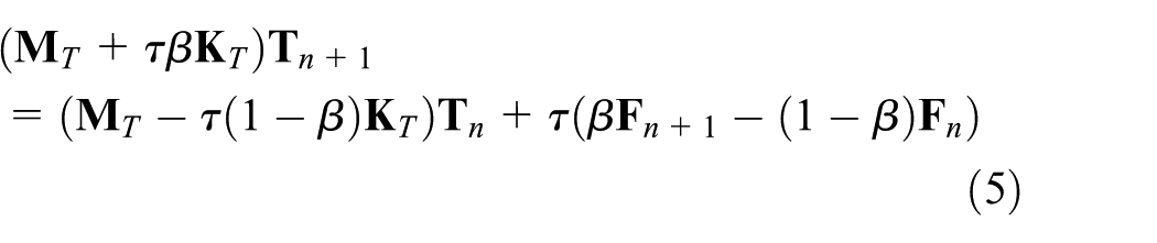
where T0 is the initial ambient temperature and th is time in hours. Equation (2) is discretized in space using four noded bilinear quadrilateral elements and is solved using the Galerkin FE method (Cook et al., 2007). Upon spatial discretization of equation (2), a first-order nonlinear ordinary differential equation in time is obtained as

where
where
Structural analysis
A beam–column element based on the Euler–Bernoulli theory is developed for structural fire analysis. Figure 1 shows a schematic of the displacements and forces considered at member level for the neutral line of such an element, and the neutral line is updated during the structural fire analysis. Due to non-uniform temperatures across the cross section for a material like RC, several fibers are considered along the length of the member, as discussed earlier. These fibers are lines passing through nodes of the 2D FE mesh utilized by thermal solver (shown in Figure 1). Temperature-dependent strain distribution and material properties are considered at each fiber level to ascertain the equivalent bending and axial rigidities of the member. While actual cross-sectional temperatures are considered for strain calculations and constitutive material behavior, temperature effects on bending are computed considering a nonlinear temperature distribution. The thermo-elastic force-deformation relations are taken directly from the work of Kassimali and Garcilazo (2010) and have been suitably extended to incorporate the effects of nonlinear thermal gradients, inelastic components of strain, and temperature-dependent material properties.
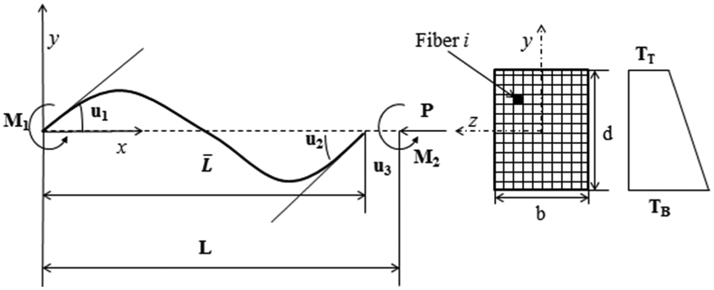
Beam–column element in member coordinate system; cross section with varying temperature profile.
The mathematical model for behavior of a beam–column element under aforementioned assumptions can be written as
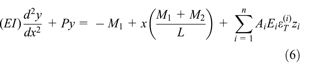
where (EI) is the equivalent bending rigidity; Ai, Ei,



where c1 and c2 are stability functions, cb is axial strain due to flexural bowing, and (AE) is the equivalent axial rigidity of the section. It is to be noted that the neutral axis typically shifts toward the colder side of a structural member due to strength degradation of the hotter side. This induces additional coupling between the bending and axial rigidities of the system if the neutral axis is not properly updated at every time-step. In this formulation, the neutral axis is updated at every time-step depending on the cross-sectional temperature profile. This allows decoupling of the bending and axial rigidities in the usual manner, as reflected in equations (7) to (9) . The effects of axial thermal deformation on bending are considered by the summation terms in equations (7) and (8) while that of bending on axial deformations are considered through the temperature-dependent bowing function cb in equation (9). Equations (7) to (9) can be written in incremental load-deflection form in member coordinate system as

where
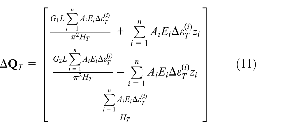
where G1, G2, H, and HT are defined as




Here,

where
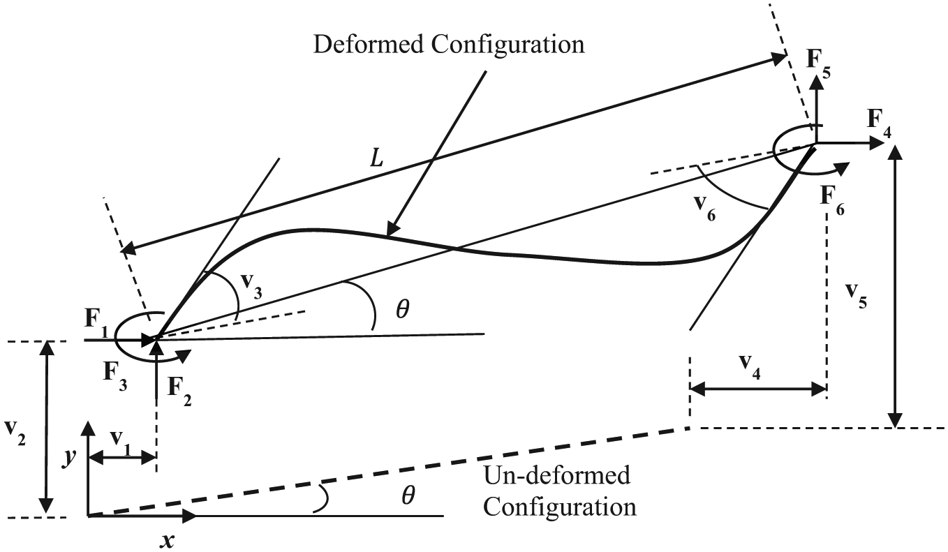
Forces and displacements in the frame element in global coordinate system.
To consider temperature-dependent constitutive behavior, it is assumed that the total strain in concrete and steel, respectively, admit an additive decomposition for each fiber as


Here, the left superscripts c and s denote concrete and steel, respectively;

where zi is the lever arm of fiber i and

where α is coefficient of linear thermal expansion which is dependent on type of aggregate and ΔT is the change in temperature. The incremental transient strain in concrete is assumed to be related to the incremental thermal strain as (Anderberg and Thelandersson, 1976)

where

where β1 = 6.28×10⁻⁶ s−0.5, d′ = 2.658×10⁻³ K−1, T is temperature in Kelvin, and
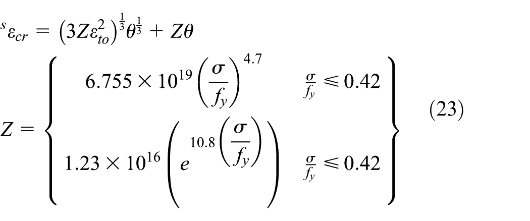
where
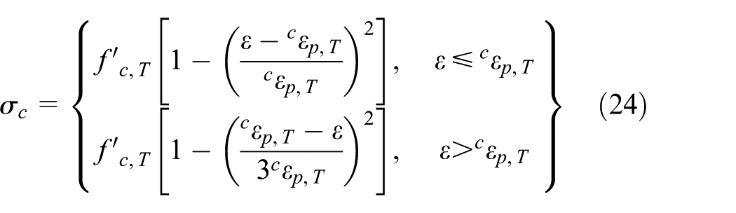
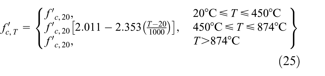

where T is temperature, and

The tensile cracking and ultimate strains are then defined as

where

Details of the algorithmic implementation of this framework are shown in Figure 3.
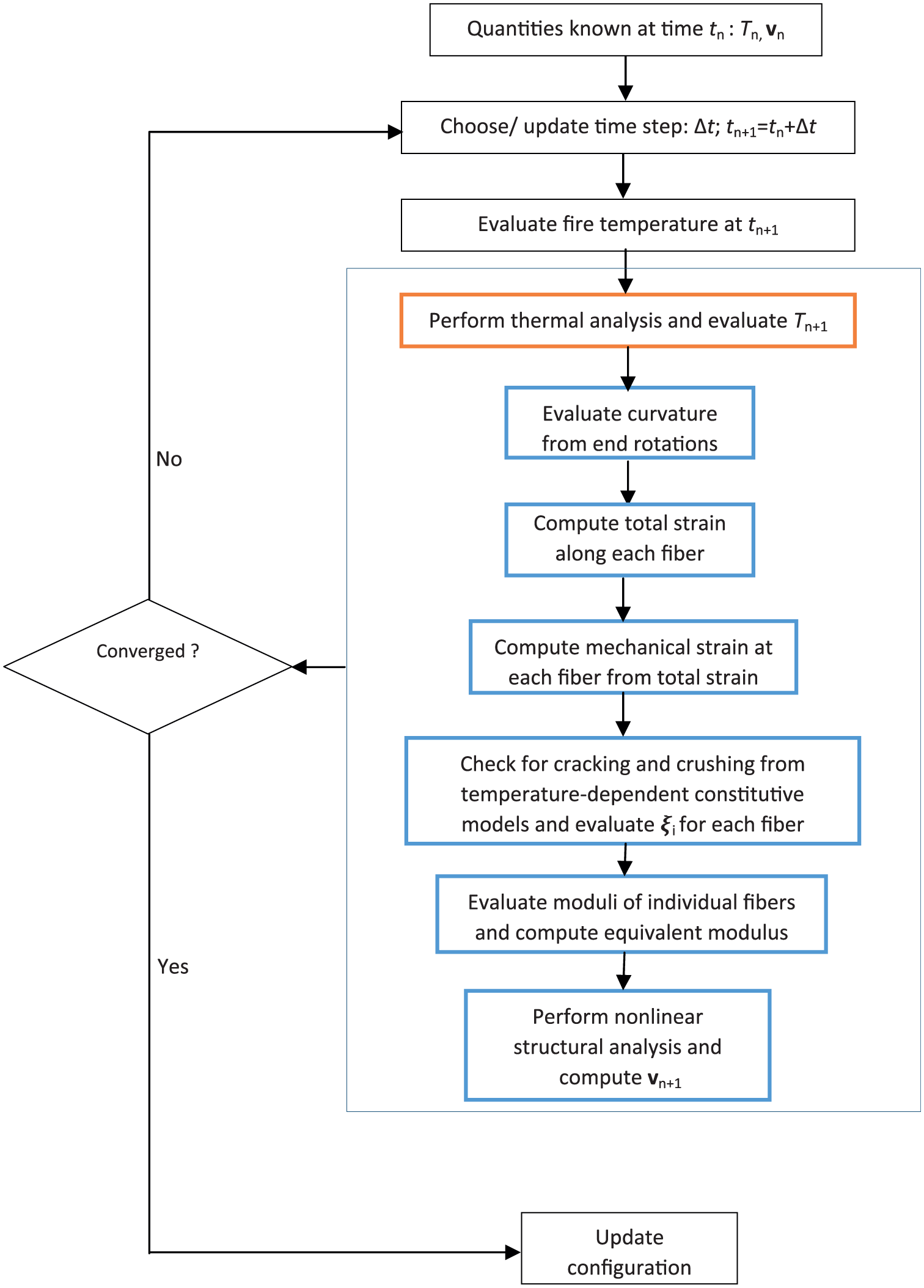
Flowchart of the developed framework.
Numerical examples
This section presents five numerical examples to demonstrate the accuracy and efficacy of the developed framework. The first example presents a verification study conducted on a beam of homogeneous linear elastic material subjected to linear thermal gradient. Next two examples present validation studies using a simply supported RC beam subjected to three-sided fire and a fixed–fixed RC column subjected to four-sided fire. The fourth example compares predictions of the proposed framework with two other existing approaches through a pinned–pinned RC beam. The final example demonstrates the applicability of the developed framework in analysis of a one-story one-bay RC frame.
Except for the verification example (which is a linear elastic analysis), failure criteria are considered in accordance with the limit states as follows:
Strength. Time up to which the capacity remains above demand (ASTM (2001)).
Rebar temperature. Time up to which temperature of any rebar remains below 593°C (ASTM (2001)).
Deflection. Time up to which the maximum deflection remains below span/20 (BS-476 (British Standards, 2004)).
The computational efficacy of the developed framework is demonstrated primarily by comparing the number of elements (of spatial discretization) required for simulation by the proposed framework with those required by SAFIR (which implements a beam–column element for structural fire analysis). As will be shown subsequently, SAFIR requires 3–4 times more elements when compared to this formulation. The computational runtimes of SAFIR and this formulation are about the same (both around 45 s for one-member analysis) due to the implementation of the developed framework in MATLAB, while SAFIR is implemented in FORTRAN. MATLAB, being an interpreted language, is known to have performance overheads when compared to a compiled language like FORTRAN or C.
The fixed–fixed RC column (example 3) has also been simulated in commercial software package ANSYS using SOLID70, LINK33, and SURF152 elements for thermal analysis and SOLID65, BEAM188, and LINK180 elements for structural analysis. Compressive crushing and tensile cracking of concrete is considered through the Willam–Warnke’s damage plasticity model (Willam and Warnke, 1974). It is to be noted that this micro-scale analysis in ANSYS is one-way coupled, that is, thermal analysis is performed first and the generated temperature profiles are utilized as input to the structural analysis. A hexahedral mesh of element size 50 mm×20 mm×20 mm has been considered for both the validation examples; this choice of mesh size is based on a detailed mesh convergence study. Full details related to the ANSYS model are not presented as micro-modeling is only used as a means to present a comparative view of the proposed framework and is not the focus herein.
All the simulations have been carried out on a desktop workstation with a 3.40 GHz Intel Core™ i7-3770 processor and 8 GB of memory. The developed framework has been implemented in MATLAB R2011a. A relative tolerance of 10−4 has been used for NR iterations for both thermal and structural analyses.
Example 1: homogeneous beam subjected to linear thermal gradient
A thermally loaded cantilever beam of length 6 m and cross-sectional dimensions


where δh is the horizontal tip deflection, δv is the vertical tip deflection, α is the coefficient of thermal expansion, D is the depth, and L is the length of the beam. Tip deflections are obtained using the developed framework assuming linearly elastic behavior with two sub-elements for various temperatures and are compared to their theoretical counterparts in Figure 4. The computational results show excellent agreement with the theoretically expected values.
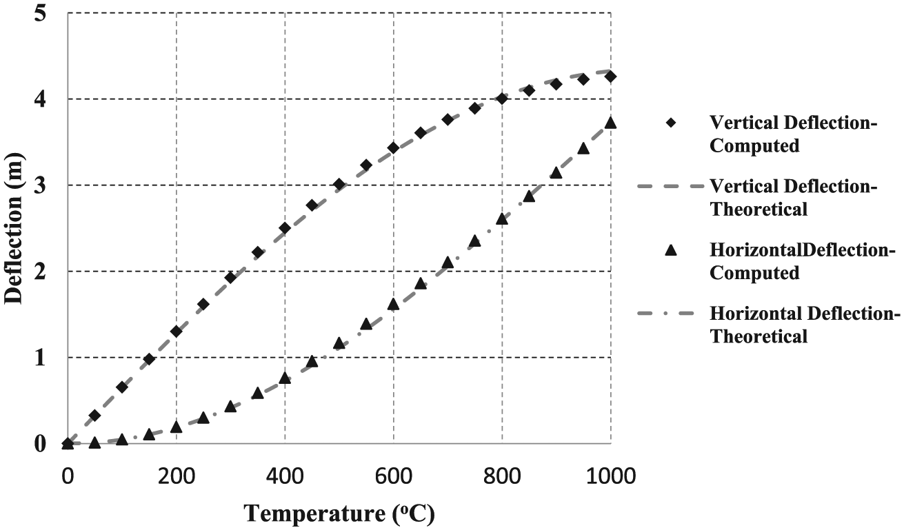
Comparison of computed tip deflections with theoretical values for example 1.
Example 2: simply supported RC beam subjected to fire
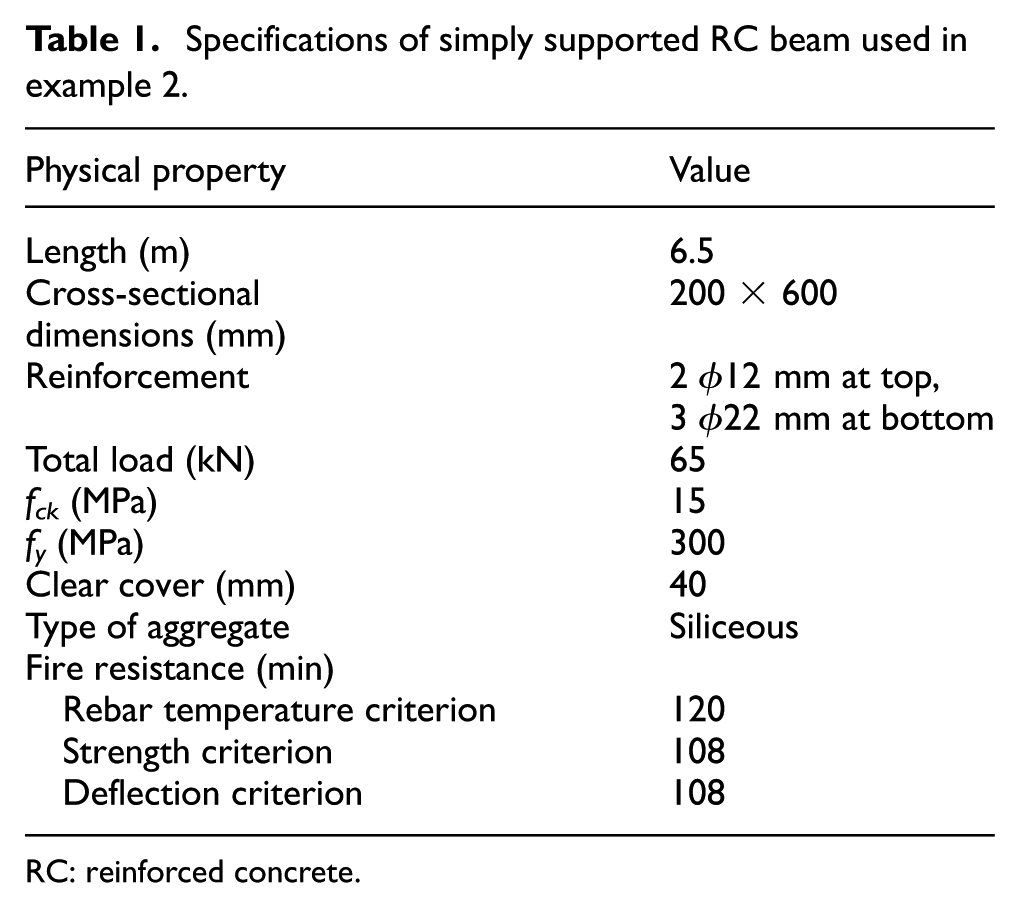
A simply supported RC beam shown in Figure 5 with specifications as in Table 1 is considered. Dotreppe and Franssen (1985) experimentally characterized the mechanical response of such a beam subjected to three-sided exposure to ASTM-E119 standard fire. Four sub-elements are used along the length of beam for analysis using the proposed method.
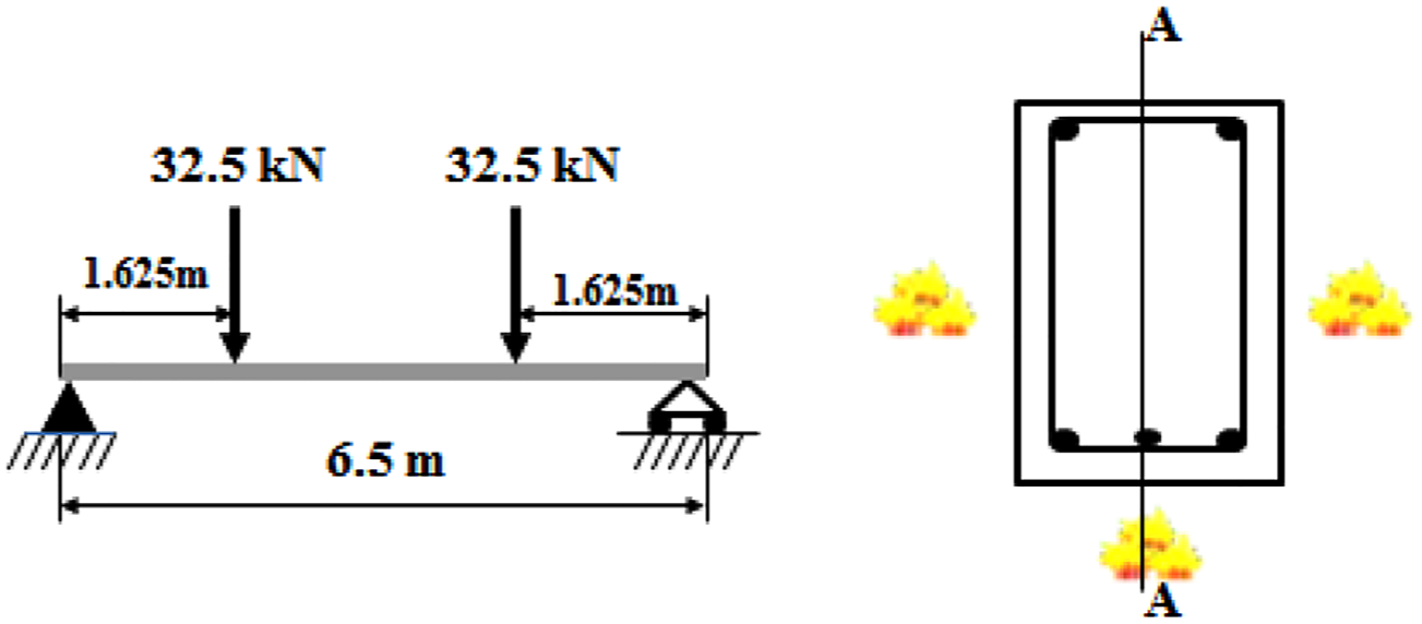
Simply supported RC beam used in example 2.
Specifications of simply supported RC beam used in example 2.
RC: reinforced concrete.
Figure 6 shows a comparison of the computed average rebar temperature with corresponding experimental observations. The observed mid-span deflection of the beam is compared with corresponding computed values in Figure 6. Same problem is analyzed using SAFIR (Franssen, 2005) with 12 sub-elements and the corresponding mechanical response history is shown in Figure 6. The number of sub-elements utilized for this numerical example using proposed framework and SAFIR are based on relevant mesh convergence studies. It can be observed that the computed response is in good agreement with the experimental observations. The computed fire resistance of this beam is reported in Table 1 based on the strength, rebar temperature, and deflection criteria mentioned earlier. Figure 7 shows temperature contours of the cross section of the beam at different times during the fire exposure. It also shows the strain distribution along line A-A of the beam. The change in mechanical strain distribution indicates an upward shift of the neutral axis with time due to cracking.
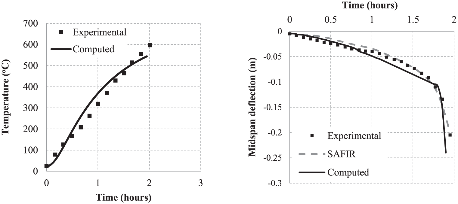
Comparison of experimental and computed rebar temperatures and mid-span deflections for example 2.
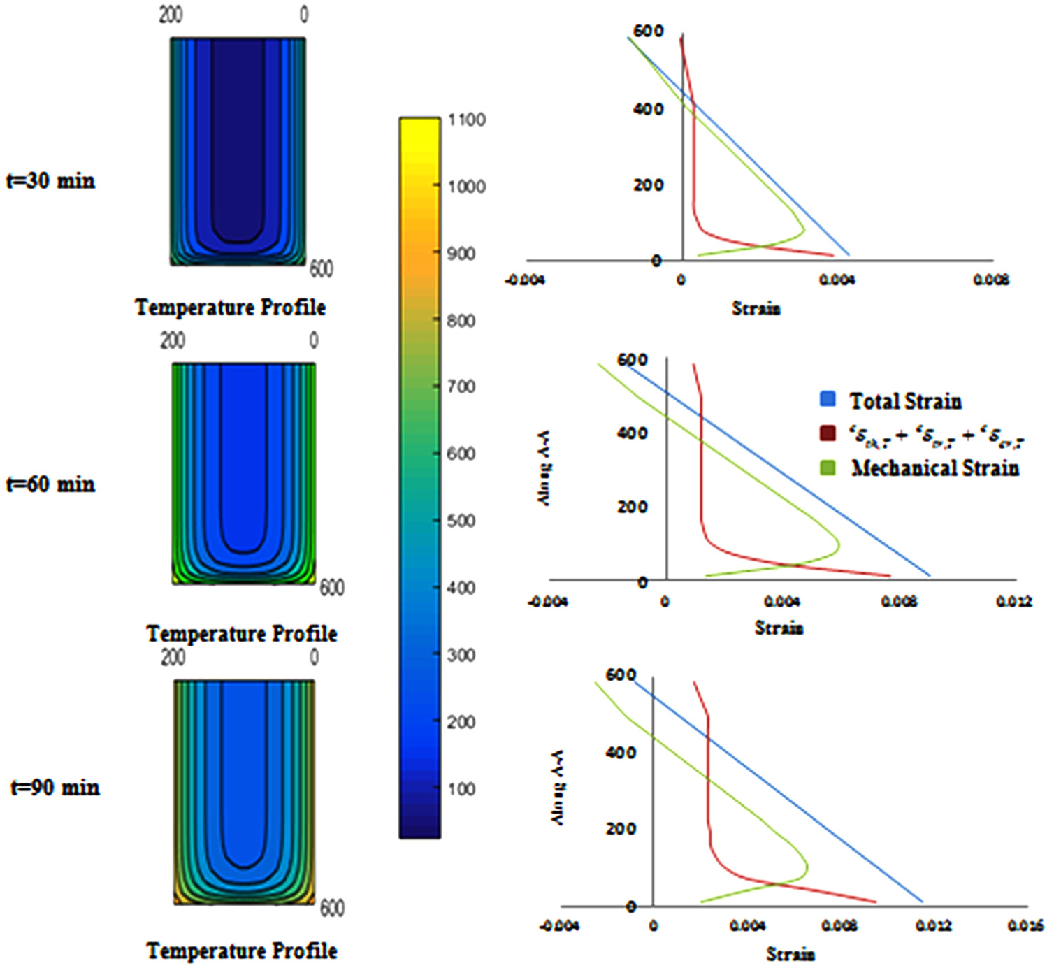
Cross-sectional temperature contours, cracking profiles, and strain distribution along line A-A for example 2.
Example 3: fixed–fixed RC column subjected to fire
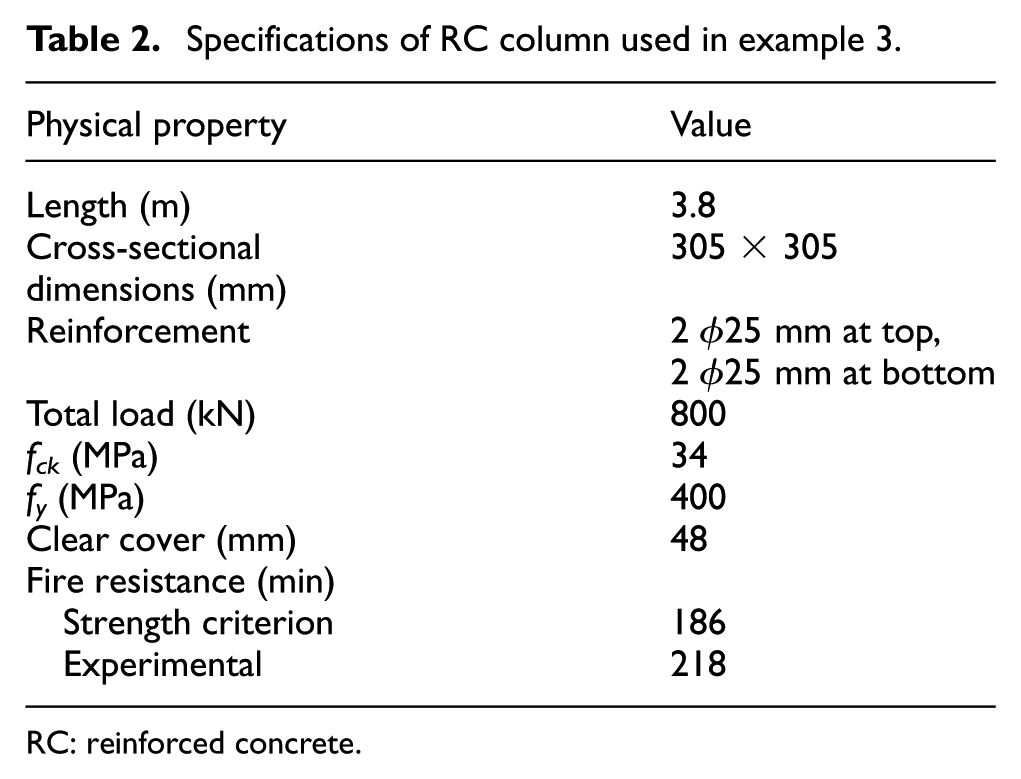
A fixed–fixed RC column shown in Figure 8 with specifications as in Table 2 is considered. Lie and Woollerton (1988) experimentally characterized thermal and mechanical responses of this column subjected to four-sided exposure to ASTM-E119 standard fire. One element is used along the length of the column for analysis using the proposed framework.
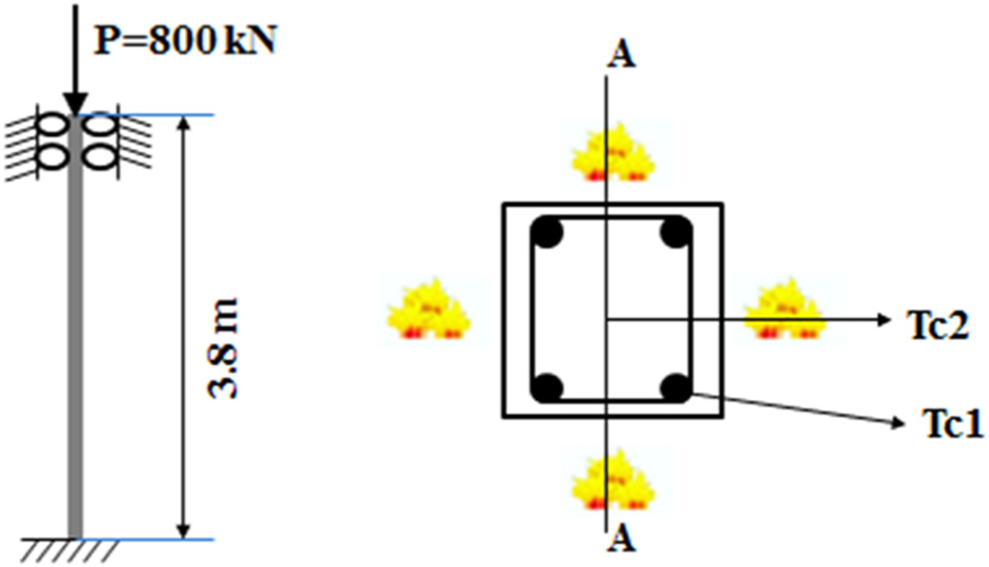
Fixed–fixed RC column used in example 3.
Specifications of RC column used in example 3.
RC: reinforced concrete.
Figure 9 shows a comparison of the computed rebar temperature at locations shown in Figure 8 with corresponding experimental observations. The experimental axial deflection history of the column is compared with corresponding computed values in Figure 9. Simulation of this example using SAFIR required four sub-elements. A comparison of the axial deflection history is shown in Figure 9. The proposed model shows good agreement with the experimental results.
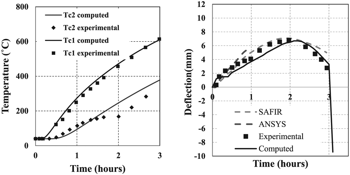
Comparison of experimental and computed temperatures and axial deflections for example 3.
The axial deflection history is shown up to 3 h beyond which the column becomes unstable. The fire resistance of this column based on simulation is found to be 186 min, which is lower than the experimentally observed failure at 218 min. Figure 10 shows the temperature contours of the cross section and strain distribution along line A-A of the column at different times during the fire exposure. From the mechanical strain distribution, a significant increase in the tension is observed with time at the central core of the column. The developed framework takes 59 s of computational time for this analysis. The computational time required by ANSYS for simulating 1-h response of this column is about 8 h (ANSYS model utilized 17,675 elements).
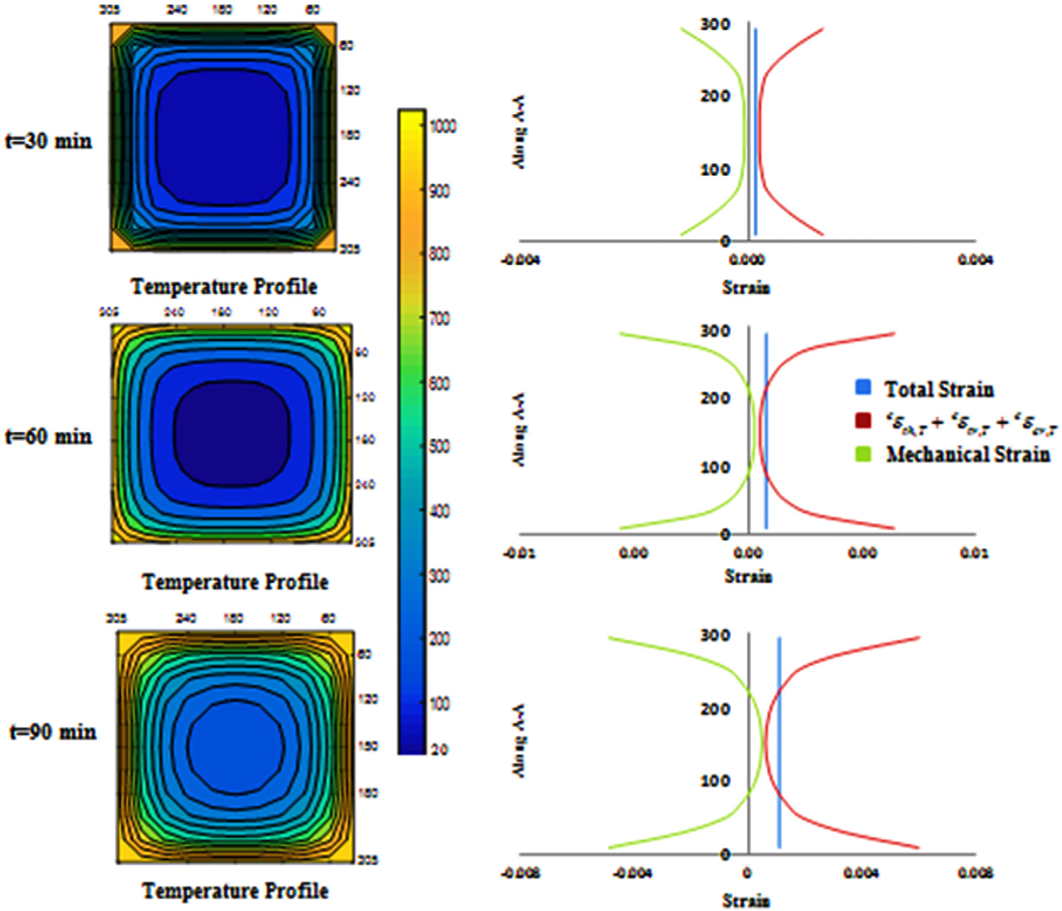
Cross-sectional temperature contours, cracking profiles, and strain distribution along section A-A for example 3.
Example 4: pinned–pinned RC beamsubjected to fire
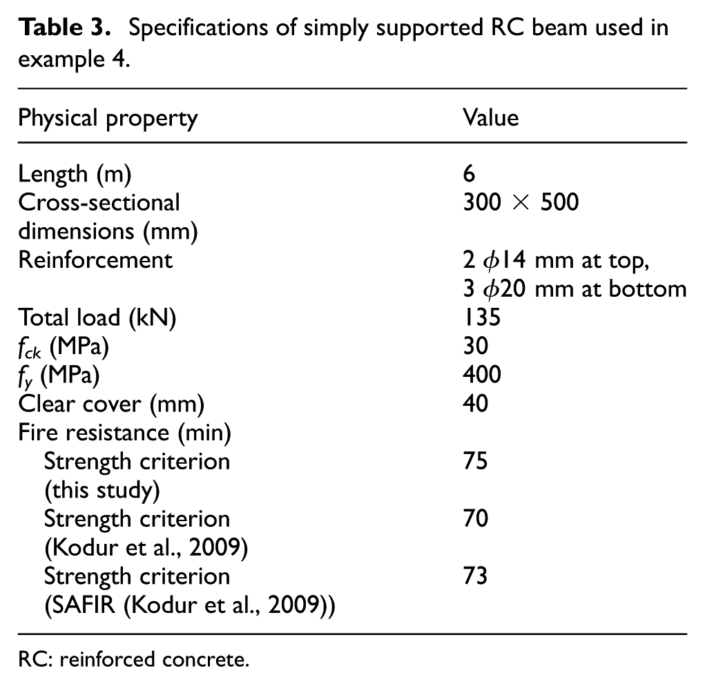
A pinned–pinned RC beam with specifications mentioned in Table 3 subjected to three-sided fire exposure is considered. Kodur et al. (2009) presented the thermo-mechanical response history of this beam for ASTM-E119 standard exposure utilizing their moment-curvature-based macro-model and compared with results obtained utilizing FE micro-modeling in SAFIR (Franssen, 2005). Thermo-mechanical analysis is performed with the developed framework using four sub-elements. The results of mid-span deflection history are shown in Figure 11 and can be observed to be in good agreement with the results presented by Kodur et al. (2009) with both micro- and macro-modeling-based approaches. The developed framework predicts slightly higher deflections compared to that of Kodur et al. (2009). This is due to consideration of bilinear material model for concrete in compression. Fire rating of the beam is computed in accordance with strength criterion mentioned earlier and is shown in Table 3. It can be observed that fire ratings estimated using the developed method is in close agreement with the ones given by Kodur et al. (2009).
Specifications of simply supported RC beam used in example 4.
RC: reinforced concrete.
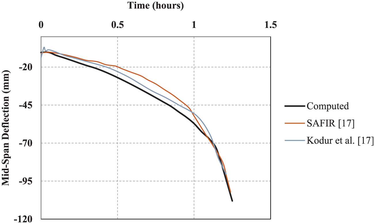
Comparison of mid-span deflections for example 4.
Example 5: RC frame subjected to fire
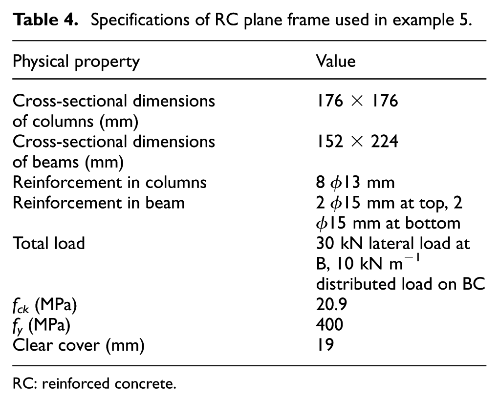
A RC plane frame as shown in Figure 12 with specifications mentioned in Table 4 is considered. Mehrabi et al. (1996) experimentally characterized the response of this RC plane frame in ambient conditions. Structural analysis is performed for the given frame in ambient conditions using the proposed framework with three sub-elements along each member. The load–deflection response in ambient conditions as computed by the proposed model is compared against the experimental observations in Figure 13. The computed results show good agreement with the experimental observations.
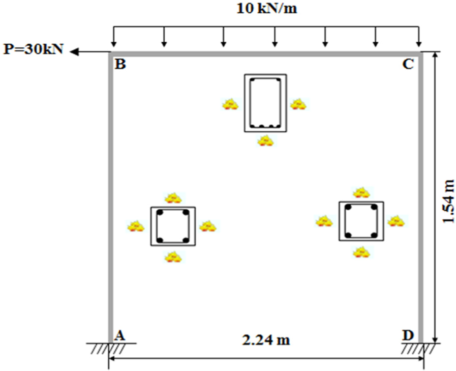
RC plane frame exposed to fire used in example 5.
Specifications of RC plane frame used in example 5.
RC: reinforced concrete.
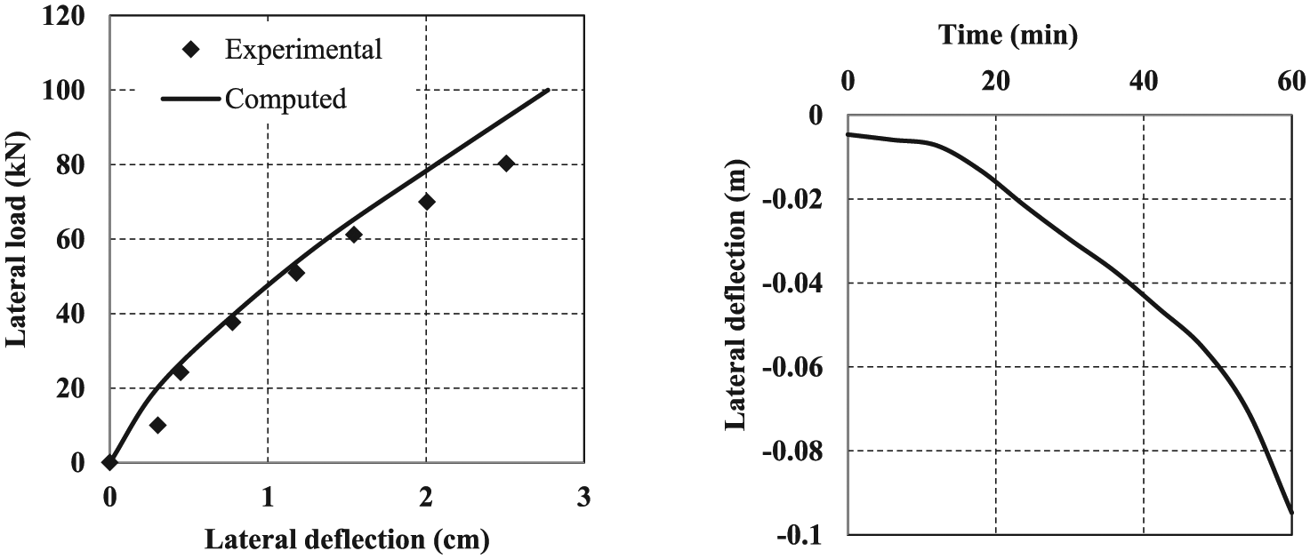
Lateral load–deflection behavior of frame in ambient conditions (left) and lateral deflection history of point B under fire exposure shown in Figure 12 (right) for example 5.
An ASTM-E119 fire exposure is provided to the frame as shown in Figure 12 in addition to the mechanical loads mentioned in Table 4. The variation of the lateral deflection at B with time is shown in Figure 13, and the deformed geometry of the frame at different times is depicted in Figure 14. The results indicate significant increase in the mechanical deformation of the frame at 60 min of fire exposure. The frame becomes unstable at 64 min due to the instability of columns AB and CD (i.e. columns fail before the beam). The computational runtime for this analysis is 203 s; whereas in ANSYS, the same analysis requires about 17 h (ANSYS model utilized 77,984 elements). This example demonstrates the capability of the developed model to predict the fire response (deformations) and expected failure time (depending on actual structural failure) of structural systems in a computationally efficient manner.
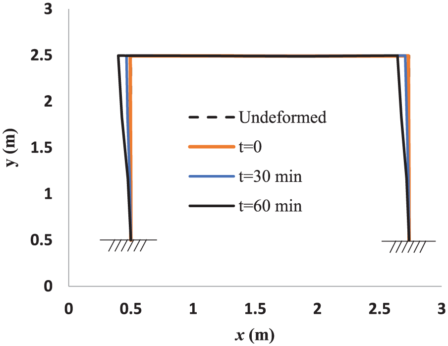
Deformed geometry of the frame for one-sided fire exposure in example 5.
Conclusion
A framework based on DSM has been developed for thermo-mechanical analysis of RC plane frames subjected to fire. The developed framework considers two-way coupling between thermal and structural analyses. A beam–column element based on Euler–Bernoulli theory has been formulated with nonlinear thermal gradients considering appropriate stability and bowing functions. Thermal analysis is performed using a 2D FE mesh for cross sections of structural members, while structural analysis considers fibers along the length of the member passing through the nodes of the 2D FE mesh used by thermal solver. Strains, irreversible damage parameter, and temperature-dependent material degradation are computed at fiber level and are then incorporated into structural analysis through equivalent bending and axial rigidities.
Consideration of temperature-dependent bowing functions intrinsically in the element formulation enables the developed framework to achieve very good accuracy in lesser number of elements as compared to analyses performed using full FE-based frameworks. This was demonstrated through five numerical examples. Predictions of the developed framework were compared against theoretical results, experimental observations, predictions by specialized structural fire analysis program SAFIR, predictions by micro-FE approaches such as models in commercial packages ANSYS, and the macro-FE approach of Kodur and Dwaikat (2008) and were found to be in good agreement.
While the proposed framework can suitably predict behavior of normal strength concrete structural members at elevated temperatures, it does not consider the effects of fire-induced spalling which are predominant in high-strength concrete members. Furthermore, the model may not yield accurate results for structural members with very small slenderness ratio (e.g. for stocky columns) as it neglects the effects of shear deformations. Given the greater computational efficacy of the developed framework in structural fire analysis of normal strength concrete framed structures, it can be readily utilized in studies that require a large number such simulations, including sensitivity analyses, uncertainty analyses, scenario-based progressive collapse analyses, and performance-based design of RC structures vulnerable to fire.
Footnotes
Declaration of Conflicting Interests
The author(s) declare no potential conflicts of interest with respect to the research, authorship, and/or publication of this article.
Funding
The author(s) disclosed receipt of the following financial support for the research, authorship, and/or publication of this article: Financial support from Start-early PhD fellowship and Excellence-in-Research fellowship of IIT Gandhinagar was acknowledged by the first and the second authors, respectively.