
Abstract
As a new structure system using containers as building modules, container building has been widely promoted around the world. However, research on the mechanical performance of container building is rare, especially the one using autoclaved lightweight concrete panels as enclosure materials. This article mainly studied the effect of autoclaved lightweight concrete panels on the mechanical performance of container building and its equivalent method. First, container finite element model with autoclaved lightweight concrete panels infilled was established, and mechanical performance and working principle of nine container models under five loading scenarios were analyzed. Then, integral equivalent model considering the effect of autoclaved lightweight concrete panels was established, and its lateral stiffness was compared with that of a pure frame model. Results show that autoclaved lightweight concrete panels could effectively enhance the lateral stiffness and ultimate capacity of container module. Equivalent spring model could effectively simulate the stiffness enhancement provided by the autoclaved lightweight concrete panels, and the story stiffness of a seven-floor container building with the effect considered rises by 60% approximately than that of a pure frame model. The results could provide technical support for economic and rational design and application of container building.
Keywords
Introduction
Besides applications in marine or highway transportation, containers are also used as temporary accommodation in field survey, disaster relief, building construction, or meteorological monitoring and usually appear in the form of one or several containers. Since 2000, permanent buildings constructed by large-scale containers have begun to emerge. The concept, “container building,” was first proposed by an American (DiMartino, 1986), who designed modular container building system in 1986 and created relevant connections. However, it was a British architect Nicholas Lacey who realized this concept. He built two container cities (Figure 1(a)) in London from 2001 to 2002, which may be regarded as the earliest vast scale container building. After that, container building was gradually promoted around the world. Typical buildings include Hamburg Cruise Container Center in Germany (2002), Amsterdam Keetwonen student housing in Netherlands (2006, Figure 1(b)), Puma concept store in America (2008), and so on.
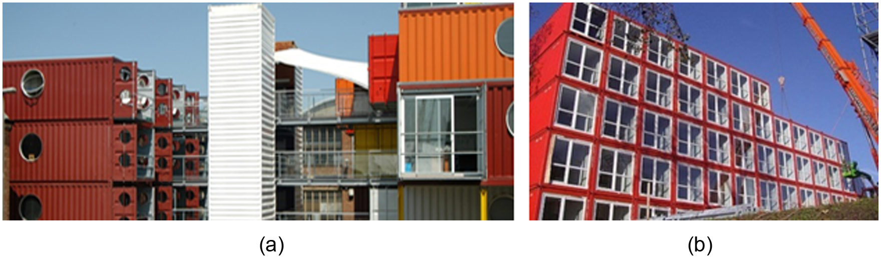
European container buildings: (a) container city and (b) Keetwonen student housing.
After the Wenchuan earthquake in 2008, China built a container school in the disaster area (Figure 2(a)), and then built a container dormitory (Figure 2(b)) and a container hotel in Zhuhai and Yantai. In 2013, an engineering construction standardization named <Technical specification for modular freight container building> was issued (CECS 334-2013, 2013), in which design criteria for container building were provided.
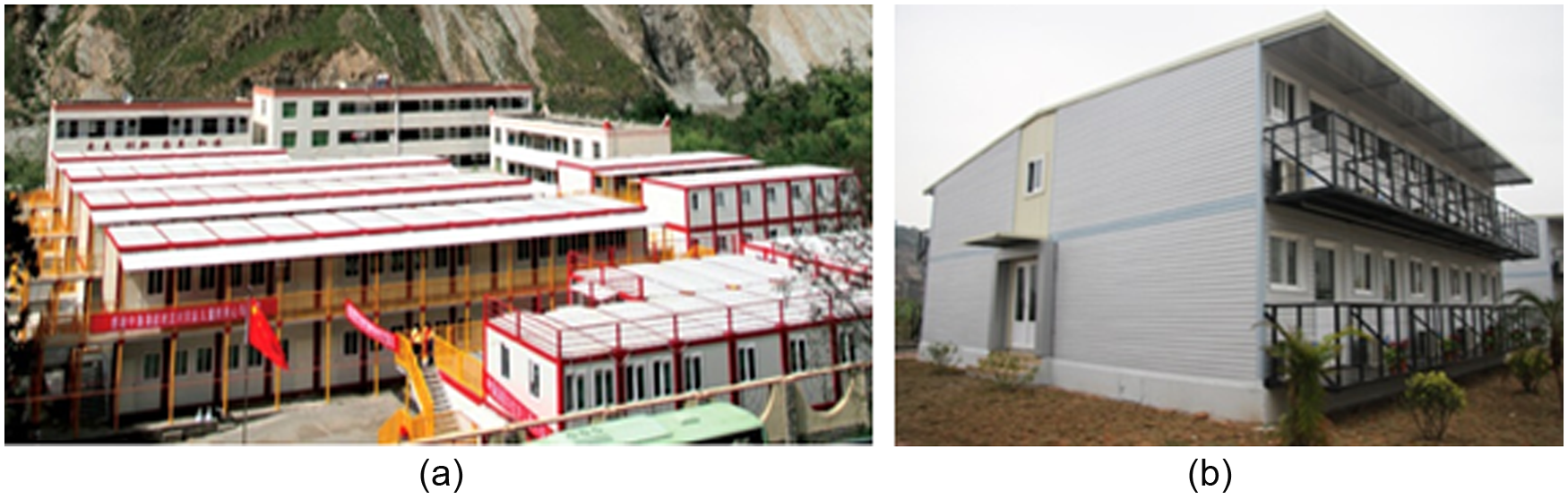
Chinese container buildings: (a) container school in Wenchuan and (b) container dormitory in Zhuhai.
The advantages of using container as building modules could be generalized as follows: (1) high modularization and industrial production; (2) high mobility and resource utilization; (3) environmental protection, energy saving, and green carbon; and (4) lightweight, high strength, and good anti-seismic property.
However, current container buildings basically apply shipping containers as modules, which use corrugated plates as enclosure materials, with poor thermal and sound insulation properties. In Japan, enclosure materials in the construction of container building adopt autoclaved lightweight concrete (ALC) panels (Figure 3), which are widely used as partition walls in concrete construction or steel structure residence nowadays. This material has characteristics of lightweight, high strength, thermal insulation, sound absorption, and fire protection and can be sawed or processed easily.
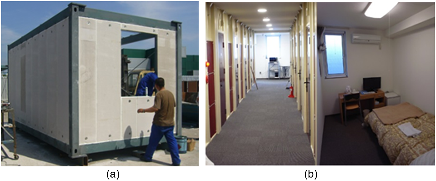
Japanese container buildings: (a) container module with ALC panels infilled and (b) internal decoration.
Present studies on container building mainly focus on its architectural aesthetics, arrangement form, and structural characteristics, while references of mechanic analysis are relatively scarce. Giriunas et al. (2012) built eight standard container modules with wallboards damaged, calculated load-displacement curves under 5 loading scenarios, and obtained the most important wallboards to lateral stiffness. Li et al. (2014) analyzed longitudinal stiffness of a 6 and 12 m container with various opening ratios of side walls and proposed empirical formulas of longitudinal stiffness and suggestion values of design shear strength. Lu et al. (2014) analyzed initial lateral stiffness and yield bearing capacity of side and end corrugated plates, and based on equivalent principle of stiffness and bearing capacity, designed and analyzed a container hotel by simplifying corrugated plates as cross braces. Nevertheless, there are no research or design codes on container building with ALC panels infilled. When designing traditional frame structures, effect of infilled wall is typically ignored for simplification, but present research on ALC panels indicates that ALC panels have certain improvement to the lateral stiffness and anti-seismic property of steel frame system (Costa et al., 2011; Edgell and Fudge, 2011; Fang et al., 2013; Varela et al., 2006).
This article centered on the stiffness promotion of container module from ALC panels and proposed an equivalent model with stiffness contribution of ALC panels considered. The research firstly established container finite element model with ALC panels infilled, then calculated load-displacement curves of different modules under external load and analyzed working principle under each loading mode. Module equivalent method with ALC panels considered was also discussed. Additionally, equivalent integral model and pure frame model of a seven-floor container building were built. Story drift and top displacement of both the two models caused by wind load were compared. Finally, suggestion for the design of container building considering the stiffness of ALC panels was provided.
Container finite element model with ALC panels infilled
Element type
Container module with ALC panels infilled was modeled by general finite analysis software ANSYS, and container steel frame and ALC panels were simulated by SOLID95 and SOLID65, respectively. SOLID65 is called 3D concrete element with reinforcing bars, which has the ability of cracking in tension and crushing in compression. Connection between ALC panels and container members was simulated by axis string—damper element, COMBIN14. The contact behavior between ALC panels and container members was simulated by CONTA174 and TARGET170.
Material constitutive model
Material of container steel component was Q235, simulated by bilinear kinematic hardening model (BKIN) in finite element model. Its stress—strain curve was defined by Young’s modulus (E), yield stress, and tangent modulus. E is equal to 206 GPa, yield stress is equal to 235 MPa, and tangent modulus was defined as 2% of E. The steel material has a density of 7850 kg/m3 and the Poisson ratio is equal to 0.3.
Compression constitutive model of ALC panels was referred to test results from a Chinese scholar (Yan, 2006), as shown in Figure 4. The curve is in non-dimensional coordinate.
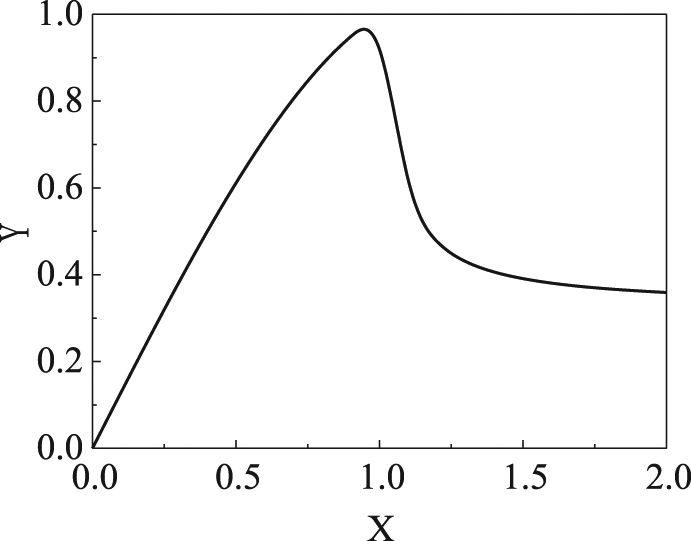
Compression constitutive equation curve of ALC concrete.
Ascending segment equation
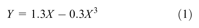
Descending segment equation
where
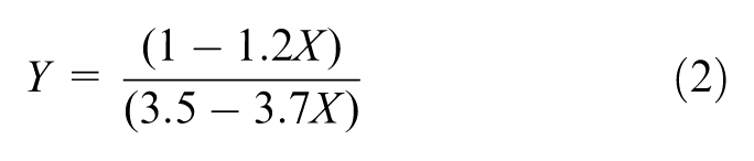
William–Warnke five-parameter failure criterion (William and Warnke, 1975) was adopted as the failure criterion of ALC panels under multi-axial stress state, as shown in equation (3)
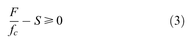
where F represents principal stress state

In order to ensure a better convergence, concrete crushing in compression was ignored, which meant
Element SOLID65 could simulate the vertical and horizontal bars in concrete by setting volume ratio of reinforcement. Ratio along the short span of ALC panels was equal to 0.3%, while that along the long span was equal to 0.45%.
The main study of this article focused on the interaction mechanism between ALC panels and container steel frame, rather than effect of different connections on integral structure; thus, the stiffness of axis string—damper element was adopted a large value, taken as
Finite element model
The size of container model is 7354 × 2438 × 3000 mm, the section of column is 200 × 200 × 6 mm, and that of beam in long span and short span is 200 × 100 × 6 mm. ALC panels are 600 mm in width and 100 mm in depth. The width of ALC panels on the head and the tail of long span is 457 mm and that of short span is 399 mm. The gaps between boards and container members are 20mm, filled with special sealant in real model. In finite element model, friction coefficient of panels was defined as 0.4 and contact stiffness and penetration tolerance factor were adopted by experienced value, 10 and 0.1, respectively (Heegaard and Curnier, 1993; Simo and Laursen, 1992; Tian and Chen, 2009). Clearances of contacts were closed automatically, which meant ALC panels and columns or beams were initially contacted. In order to simulate the relative sliding of panels, maximum contact friction stress was equal to 1 MPa. If equivalent shear stress of the contact surface reached to 1 MPa, panels would begin to slide.
The mesh size of ALC panels was 0.1 m, and that of container steel component was 0.05 m. String elements were installed between side walls, end walls, roof, floor, and beam members for simulating the connections and the count of contact pairs reached to 82.
Constraints
Connections of container models are given in the mentioned technical specification (CECS 334-2013, 2013), including welded connection and high-strength bolted connection. Welded connection is seldom used for its complex construction and inconvenient disassembly. High-strength bolted connection joints the left, right, top, and bottom container modules through a gusset plate, but it is limited in constraint of rotation of container modules. Therefore, the constraints at the end of columns were assumed articulated in this article. This function in solid finite element model was realized by method of multipoint constraints (MPC).
Mechanism analysis of container module with ALC panels infilled
Referring to the method of Giriunas et al. (2012), the stiffness of container module under different external loads was analyzed in the lack of side walls or end walls, exploring the influence of ALC panels in different locations on the stiffness.
Nine container modules and five loading scenarios
According to different house types of container building, nine common models were installed, displayed in Figure 5, and based on the container international standard (ISO 1496-1:1990, 1990), five loading scenarios were considered, displayed in Figure 6.
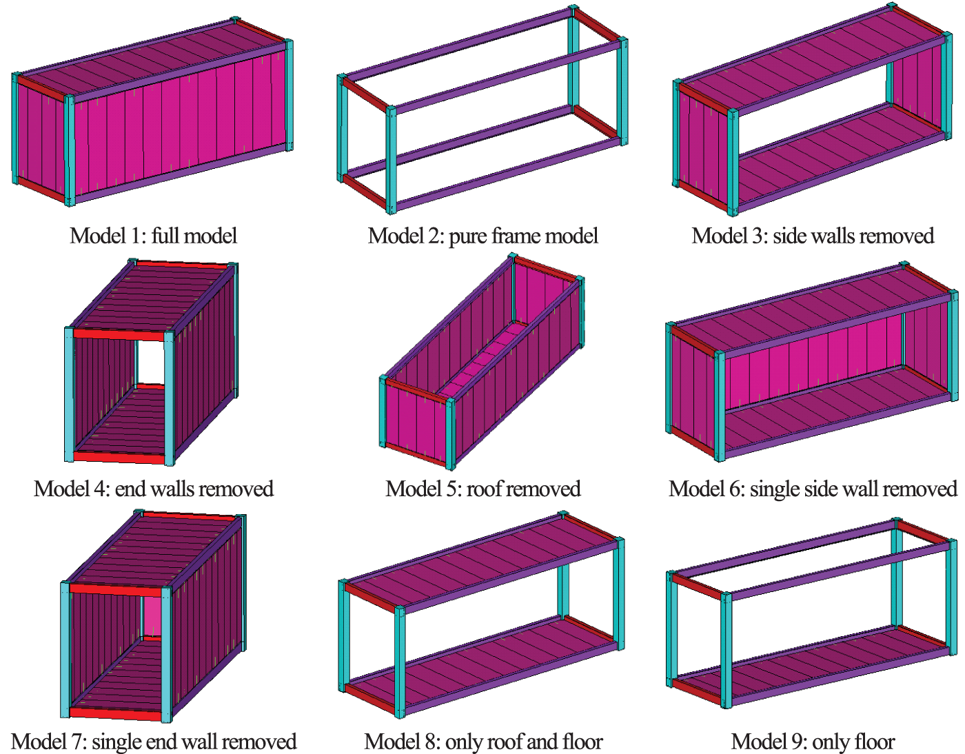
Container models with various ALC panels infilled.
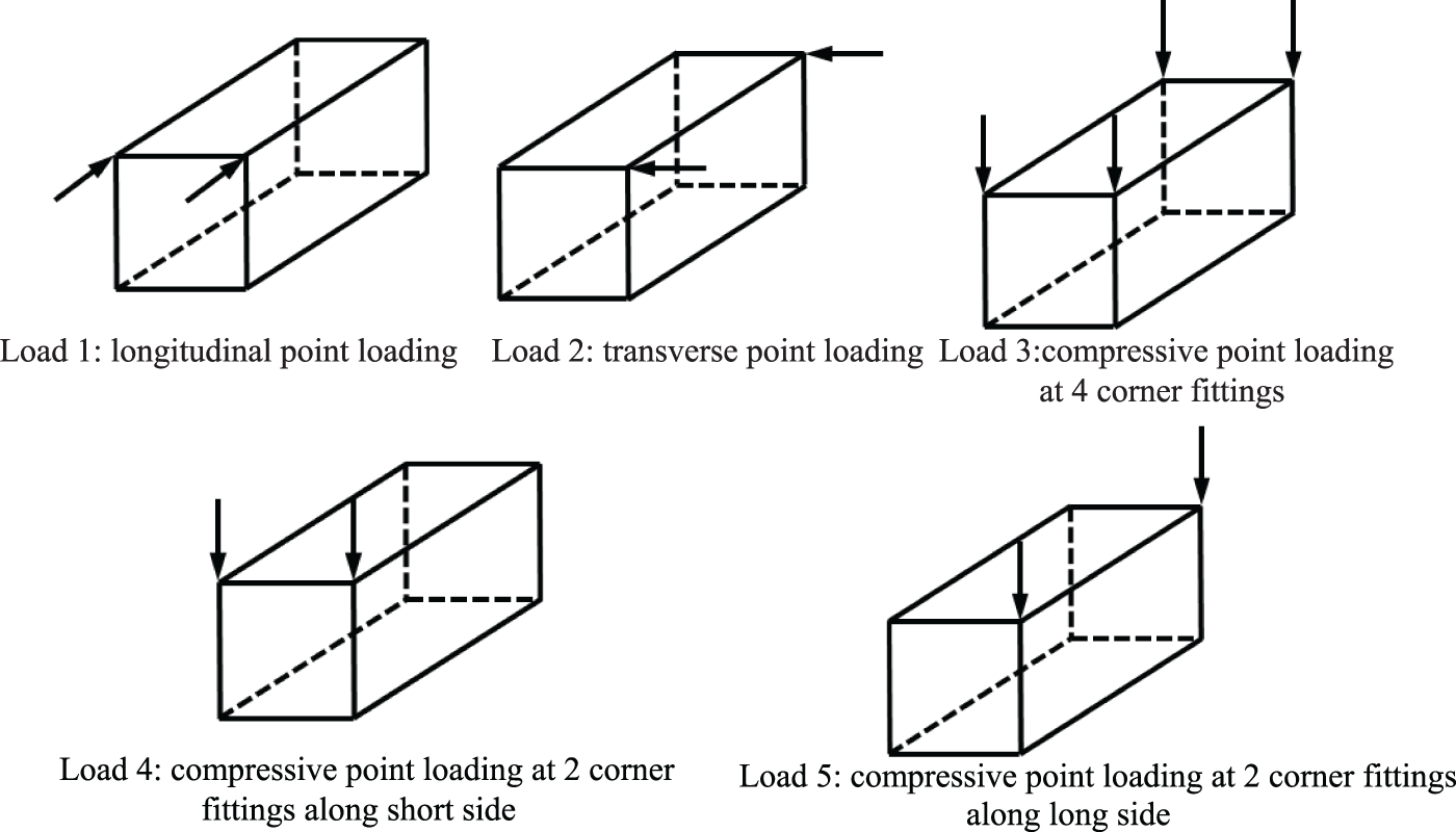
Five loading scenarios.
Load–displacement curve
The inflection point of load–displacement curve was defined as the model elastic ultimate bearing capacity, and the promotion impacts of different located ALC panels on the stiffness were also compared.
Curves under Load 1
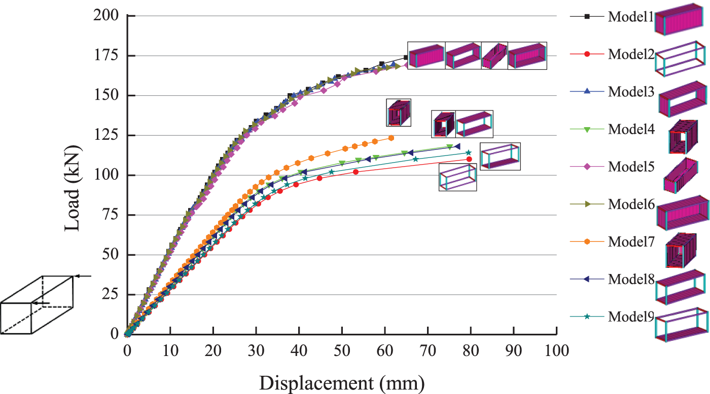
Synchronously longitudinal load was applied on the top of the columns and load–displacement curves of every model are shown in Figure 7. Obviously, the longitudinal stiffness of container module was mainly contributed by the two side walls and roof, while floor and end walls had no benefits on the promotion of module stiffness. When lacking one side wall, the longitudinal stiffness of container module decreased significantly. The elastic ultimate bearing capacity of Models 1, 4, 5, and 7 was approximately 180 kN and their curves had a horizon jump beyond the load of 180 kN; after that, extrusion between panels became tighter and then the lateral stiffness declined slowly. The load–displacement curves had a yield platform at 330 kN; meanwhile, displacement reached 75 mm. After that, module capacity of resisting lateral load continued to rise. In these above-mentioned modules, the elastic lateral stiffness was about 5.72 kN/mm. Because steel tangent modulus was defined only 2% of E, Models 2, 3, 8 and 9 lost the ability to bear lateral load after side beams yielding. And the yield deformation was 60 mm or so, which appeared earlier than Models 1, 4, 5, and 7. The elastic ultimate bearing capacity of these modules was about 80 kN and lateral stiffness was 1.33 kN/mm. Thus, the lateral stiffness of module with two side walls was 3.3 times higher than that of module without any side wall infilled. The capacity of Model 6 with one side wall lost was about 113 kN, and stiffness was 2.88 kN/mm, 50.34% of Model 1 and 2.17 times higher than Model 3. In lack of one side wall, the stiffness of the two sides in Model 6 was inconsistent so that the module had shear deformation under longitudinal load. However, the roof had higher in-plane stiffness, which promoting the distorting coordination of the two sides and reducing the deformation of the side without panels. As a result, the module integral rigidity was increased and the maximum displacement reached 90 mm when yielded. Only in Model 6, the roof worked with the single side wall to resist lateral load, in other models, the roof had no effect. On account of the lack of out-of-plane stiffness, the end wall did not participate in the work under longitudinal load.

Curves under Load 1.
Curves under Load 2
Synchronously transverse load was applied on the top of the columns and load–displacement curves of every model are shown in Figure 8. It was obvious that the transverse stiffness of container module was mainly produced by end walls, rather than the roof or side walls. Curves of Models 1, 3, 5, and 6 were coincident. The elastic lateral stiffness of these modules was about 120 kN, and stiffness was 4.80 kN/mm. When the maximum deformation reached 25 mm, the whole module entered into elastic–plastic stage. Because the length of end wall was only a third of side wall, transverse elastic capacity was 60 kN lower than the longitudinal, and the stiffness also declined by 16%. Curves of Models 2 and 9 were closed to each other. The capacity and the stiffness were 85 kN and 2.70 kN/mm, respectively. The transverse elastic capacity of the pure frame was higher than the longitudinal elastic capacity, for the linear rigidity of end beam was higher than the side beam. Curves of Models 4 and 8 were almost the same, in which the capacity was 90 kN and the stiffness was 2.90 kN/mm, slightly higher than Models 2 and 9. It could be drawn that the roof had a certain effect on the transverse stiffness. The elastic capacity of Model 7 with one end wall was 95 kN and stiffness was 3.05 kN/mm, just increasing by 13% than Model 2 and being 63.54% of Model 1. Compared to the improvement of one side wall on the longitudinal resistance, one end wall was not obvious enough on the transverse resistance. Although the existence of roof forced the two end sides with different stiffness to work together, the direction of the module shear deformation was just parallel to the long span of ALC panels, and the gaps between panels made the collaboration unapparent.
Curves under Load 2.
Curves under Load 3
Synchronously vertical load was applied on the top of the columns and load–displacement curves of every model are shown in Figure 9. Under vertical load, the elastic ultimate bearing capacity of every module was about 1050 kN and stiffness was roughly the same, around 360 kN/mm. Model 1 and Model 5 with both end walls and side walls still had greater capacity after the stiffness declining. When load reached 1300 kN, the curve began to rise smoothly and the integral model entered into plastic state. Models 2, 8, and 9, having no surrounding materials, lost continued bearing capacity immediately the columns yielded. Curves of Models 3, 4, 6, and 7 were among the mentioned two types of modules. These modules had elastic–plastic state and still had bearing capacity after columns yielded. And the curves began to rise smoothly at the load of 1200 kN. It should be noted that only with the existence of the four enclosing panels could the module have greater capacity, if one panel lost, the capacity declined by 100 kN. However, the existence of the four panels had no effect on the stiffness improvement of modules under vertical load.
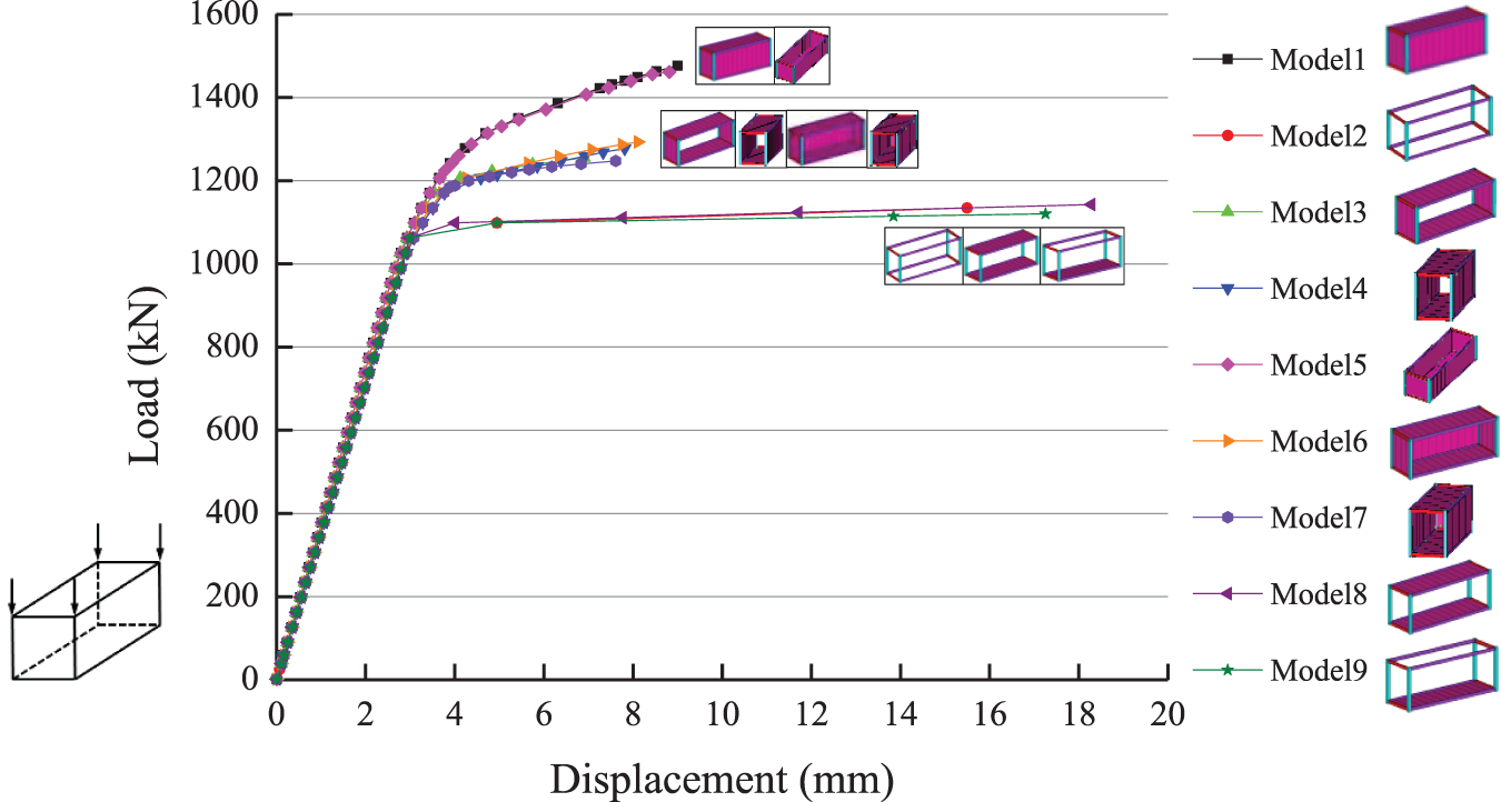
Curves under Load 3.
Curves under Load 4 and Load 5
Synchronously vertical load was applied on the transverse column top and the longitudinal column top, respectively. And load–displacement curves were similar to that under Load 3. Every module had the identical vertical stiffness and elastic ultimate bearing capacity, among which, modules with four walls had the strongest capacity, modules with one wall lost came second, and modules bearing vertical load only by columns had no continued capacity after the columns yielding.
Interaction mechanism of container module with ALC panels infilled
Mechanism of module under lateral load
It could be found in Figures 7 and 8 that the initial stiffness of modules with walls was higher than that without walls, which meant when the module began to be stressed, the ALC panels were instantly involved in the lateral resistant with container columns.
Taken one end wall and one side wall from Model 1, stress distribution and crack distribution of ALC panels were analyzed under lateral load from two directions. Figure 10 displays the first principal stress distribution of the end wall and the side wall at the elastic ultimate bearing capacity. It could be seen that ALC panels were in tension state along the diagonal. Principal tensile stress was distributed along one diagonal, while principal compressive stress was distributed along the other diagonal. ALC panels were similar to tensile–compressive diagonal braces. Cracks are shown in Figure 11, mainly distributed at diagonal region. In the middle panels, cracks developed relatively rapidly and most elements had been cracked. At this point, the maximum Von Mises stress of end beams and side beams appeared in flange edge and the values were 229 MPa and 223 MPa, not yet yielded.
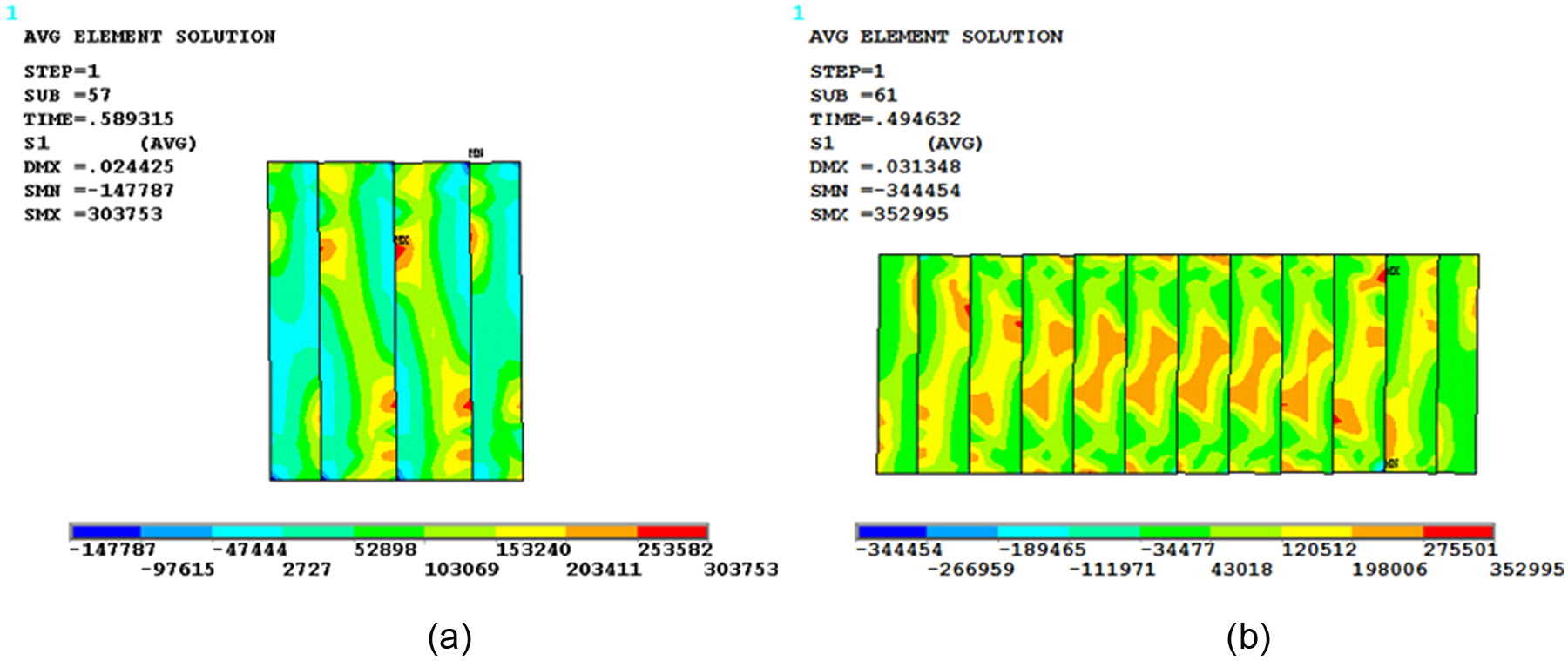
First principle stress of (a) end walls and (b) side walls.
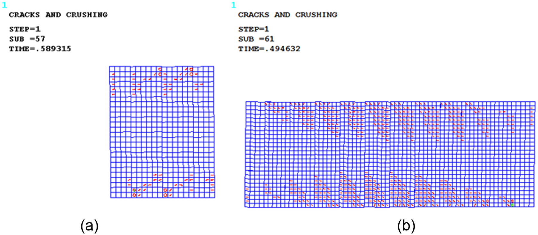
Crack distribution of (a) end walls and (b) side walls.
The mechanism of articulated module under lateral load could be summarized as follows: during the elastic state, ALC panels worked together with steel frame and carried the most lateral load; panels were pressed between each other; at the point of elastic ultimate bearing capacity, cracks had developed to a certain extent and horizontal deformation of module began to jump; after that, the lateral stiffness of module gradually declined and deformation increased; the end of the beams first yielded and formed plastic hinges and then the steel frame lost the bearing capacity totally, which in turn transferred all the internal forces of the module to ALC panels; finally, cracks largely developed and the lateral stiffness of the module considerably dropped. Since the number of panels in end wall was less than that in side wall, lateral stiffness provided by the end wall was not strong enough. After the load exceeded elastic ultimate bearing capacity, the end beams had yielded gradually. When plastic hinge formed, end walls had developed large-scale cracks and had almost lost the ability of bearing lateral loads. After that, the load–displacement curve became smooth, as shown in Figure 8.
Mechanism of module under vertical load
Figure 12 displays Model 1 deformation under Load 3 at the load value 1400 kN. The figure indicated that the deformation centered on the column top. Drove by columns, end beams and side beams had bent.
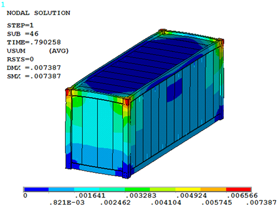
Deformation of Model 1 under Load 3.
Due to the little flexural rigidity, beams could not drive all the panels to work together, only the panels closed to columns being stressed. During the elastic state, the vertical load was mainly carried by columns, so the vertical rigidity of models with walls and models without walls was the same. When columns yielded and the module entered into elastic–plastic state, vertical load was distributed to the end of end and side beams and then transferred to ALC panels through the beams bending deformation. The ultimate capacity of modules with four surrounding walls was higher than that of the modules with one or more walls lost, because the former had one or more steel beams to transfer the load. After the end beams or side beams had yielded, the module also became plastic and lost the continued bearing capacity.
Structural analysis method with the effect of ALC panels considered
Simplified modeling method for ALC panels
Currently, there are three simplified modeling methods for steel frame structure with ALC panels infilled on the consideration of ALC panels effect, namely, equivalent spring model (Yang et al., 2013), equivalent single diagonal bar model (Holmes, 1961; Liauw and Kwan, 1984; Smith, 1966), and equivalent multiple diagonal bars model (Gao, 2012). And simplified modeling methods for container module with corrugated plates considered mainly include equivalent cross braces model (Lu et al., 2014) and so on. The following part is a simple introduction of the three simplified modeling methods.
Equivalent spring model
The way equivalent spring model simulating the function of ALC panels is setting horizontal springs at the top of columns (Figure 13(a)), so the story lateral stiffness of steel frame could be improved. Rigidity of the horizontal springs could be defined as the difference between the stiffness of solid model and that of pure frame model.
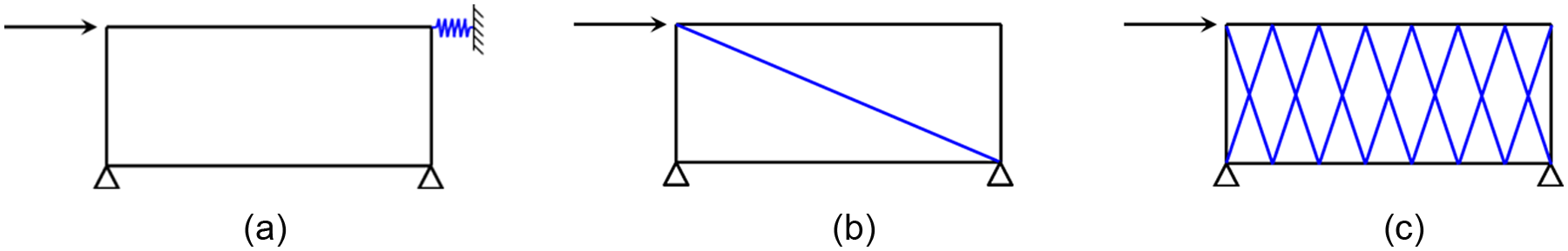
Three equivalent models: (a) spring model, (b) single diagonal bar model, and (c) multiple diagonal bars model.
Equivalent single diagonal bar model
This model simplifies the enclosure material consisting of ALC panels as one compressive brace along the diagonal of steel frame (Figure 13(b)). Thickness of the brace is the same with that of ALC panels, while the width could be defined through comparison between solid model and simplified model, whose standard is that two models have the same horizontal displacement of columns. This simplified modeling method for steel frame with ALC panels considered is similar to the simplified method for container module with corrugated plates considered, but the distinction is that the former just builds a single bar model, considering ALC panels will become invalid when tensioned, while the latter builds cross braces, considering the tension capacity of corrugated plates. However, the integral stress distribution of ALC panels in equivalent single diagonal bar model is inconsistent with that in container module.
Equivalent multiple diagonal bars model
This model simplifies every ALC panel as cross compressive braces along the diagonal and builds several compressive braces in the steel frame (Figure 13(c)), simulating the beneficial effect of ALC panels. Determination of every compressive brace parameters is the same as that of equivalent single diagonal bar model. The stress distribution of this model is consistent with the true stress distribution when ALC panels and container frame working together, just ignoring the little tension stiffness of ALC panels. But calculation indicates that this model can be only used in steel frame structure where base-beam is totally fixed or horizontal member has strong rigidity. As only the end of columns is restricted and the beam beading rigidity is not strong enough, the equivalent result is not desirable for container module.
Based on the introduction above, this section used equivalent spring model to establish simplified model for container module with ALC panels infilled and compared it with solid model, evaluating its applicability. And then, the equivalent module was used in a seven-floor container building for static analysis and the promotion of the whole structure stiffness from ALC panels was assessed.
Applicability of equivalent spring model
Before building the equivalent spring model, beam element model of pure frame was established in axis size of each solid component and differences between beam element model and solid element model were compared. BEAM 189 was used in the beam model, with the same material parameters of solid model. Results showed that these two models had coincident load–displacement curves under longitudinal load and indicated that the equivalent spring model could be built on the beam model.
Spring elements were arranged on one side of the container and lateral load was applied on the other side. The spring element type adopted COMBIN14, whose stiffness was determined by the difference between solid model and pure frame model. Figure 14 displays the load–displacement curves of equivalent spring model of Model 1 under Load 1 and Load 2, in which the elastic stage of equivalent spring model was in good agreement with that of solid model. However, due to spring elements could not simulate the crack of concrete, differences in elastic–plastic state between the two models were obvious. Thus, there are some limits in using spring elements to simulate the improvement of module stiffness by ALC panels, that is, the equivalent model could only simulate the lateral stiffness of solid model in elastic stage.
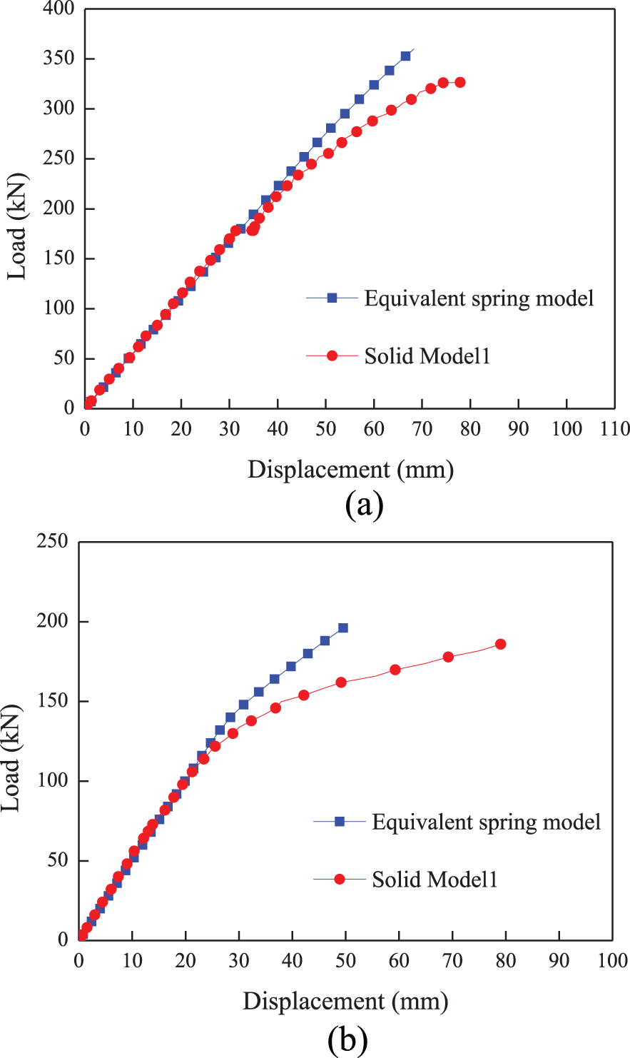
Comparison curves of Model 1 under (a) Load 1 and (b) Load 2.
When simulating the contributions of roofs in Model 6 and Model 7 to the lateral stiffness, spring rigidity on the side with walls could be determined by the stiffness difference between Model 1 and Model 2, and that on the side without walls could be determined by the stiffness difference between Model 6, Model 7, and Model 2. Load–displacement curves are shown in Figure 15. Transverse curves (Figure 15(b)) of the two models were coincident quiet well during elastic stage, while longitudinal curves (Figure 15(a)) had some errors. The spring elements exaggerated the effect of roof and the stiffness of the equivalent spring model was 14% higher than that of solid Model 6. In order to guarantee the equivalent result more accurate and convincing, the spring rigidity on the side without walls in Model 6 was reduced accordingly and new comparison is shown in Figure 16.
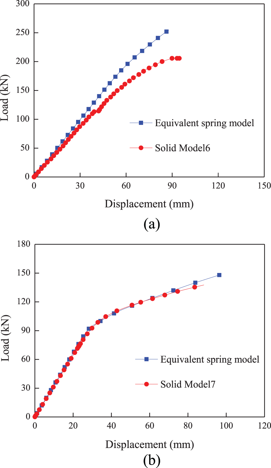
Comparison curves of (a) Model 6 under Load 1 and (b) Model 7 under Load 2.
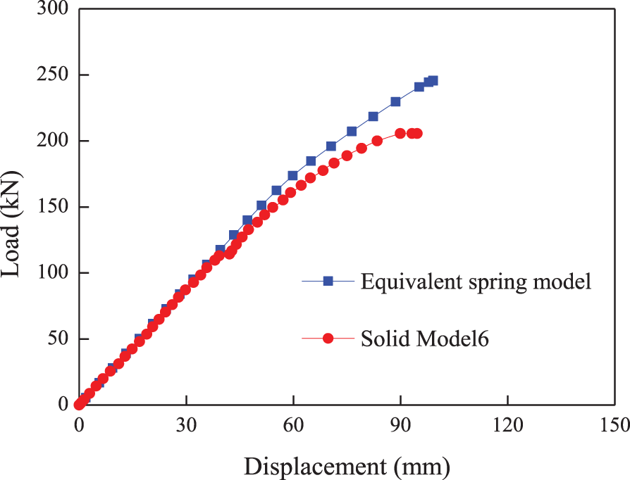
Comparison curves of Model 6 under Load 1 after spring element rigidity reduced.
Comparing the steel frame stress distribution of solid model and equivalent model under Load 1 and Load 2, it could be found that the stress distributions of the two models under lateral load were similar but stress magnitude was obviously different. Under Load 1, maximum stress of solid model reached 223 MPa, while that of equivalent spring model was 190 MPa, differing about 17%. Under Load 2, maximum stress of solid model was 229 MPa, while that of equivalent spring model was equal to 240 MPa. The former was still elastic while the latter had entered into plastic stage. Thus, equivalent spring model could effectively simulate the improvement of module stiffness from ALC panels, but could not truly reflect the components stress of solid model.
Analysis on a seven-floor container building with ALC panels infilled based on the equivalent spring model
Figure 17 presents a plan of a seven-floor container building consisting of the mentioned container modules, with 39.328 m in long axis, 12.900 m in short axis, and 19.500 m in height. Standard container module was used in the former six layers with floor height of 3 m, and the seventh floor was roof with height of 1.5 m. Totally, there were four housing types. To be specific, A type was consisted of two containers, whose area was 36.26 m2; B type had three containers, and its area was 54.39 m2; C type was consisted of one container with area of 18.13 m2 and D type possessed one and a half containers, and the area was 27.20 m2. Every standard floor included three A houses, two B houses, two D houses, and one C house. Four small-scale container modules, which dimension was 4896 × 2438 × 3000 mm, were added as elevator well, stair hall, and corridors in the center.
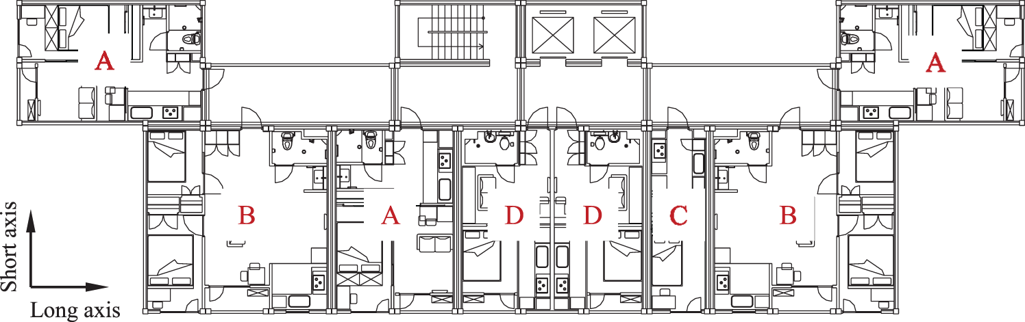
Plan of a seven-floor container building.
Based on the mentioned housing design and the location of doors and windows openings, container modules in this building could be classified into several models, as shown in Figure 18. Spring elements were set on the top of every column in corresponding modules. Definition of the spring element stiffness was the same with that of equivalent spring model (stiffness of springs in elevator wells and stair halls could be determined by the difference between Model 1 and Model 2 under Load 2). The size and the element type of columns and beams was the same with that of the above-mentioned modules. The whole model is displayed in Figure 19. The column end was defined as a hinge, and connections between container modules were achieved by coupling nodes three-way translational degrees of freedom. In order to eliminate the influence of vertical displacement and just consider the effect of module story drift on spring elements, the vertical freedom of the other side node of spring element was coupled to that of the top node of the module column, and the freedom along the loading direction was coupled to that of the end node of the module column. Roof stiffness improvement from ALC panels was ignored, which meant there were no spring elements setting on the roof modules.
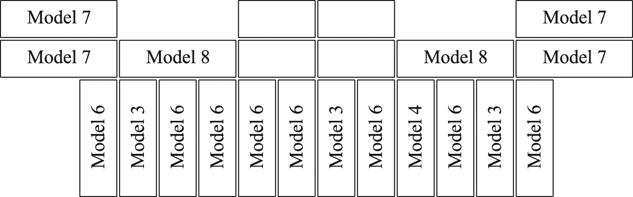
Module classification of the seven-floor container building.
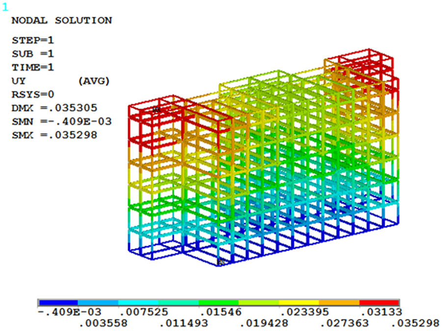
Displacement contour of equivalent integral model (m).
Calculation showed that for the above container building without any auxiliary structural measures, its lateral stiffness of short axis was weak; thus, spring elements and wind load were only applied on the structure short axis for contrastive analysis. Wind load was determined by Chinese load code (GB50009-2012, 2012) and the surface load was equivalent as linear load, applied on the container beams. Table 1 displays the top displacement of the building and story drift of the pure frame model and the equivalent integral model. It could be seen that the top displacement of equivalent integral model was lower and the story drift was declined by 32.99% at least than that of the pure frame. Meanwhile, the story stiffness had increased by 60% approximately. It was obvious that the structure rigidity was largely enhanced after considering the effect of ALC panels.
Displacement of the top of the building and story drift.
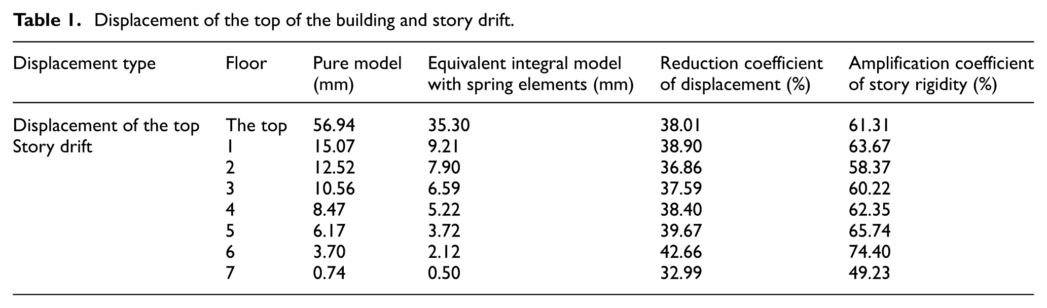
Generally, member section of container pure frame model is controlled by the story drift under wind load. Based on the above analysis that ALC panels could improve story stiffness by 60%, the promotion should not be ignored when calculating the serviceability limit state. It can be realized by broadening the limit of inter-story displacement angle of standards, and the broadened scope could be determined by story rigidity amplification coefficient. In consideration of the differences of maximum components stress between equivalent model and solid model, when calculating the ultimate limit state, cross section of container members should still be mainly selected according to pure frame model, and component strength and stable bearing capacity are the dominant indexes.
Conclusion
This article briefly described the development of container building, summarized its characteristic, and mainly researched on the property of container building with ALC panels infilled. Conclusions can be derived as follows:
Side walls and end walls could effectively enhance the lateral stiffness of module under lateral load, while roof has some effect on the stiffness promotion only when lacking side walls or end walls. Under vertical load, the existence of ALC panels could not improve the vertical rigidity, but could largely increase the ultimate bearing capacity of modules.
ALC panels work together with the frame initially under lateral load, and the stress state of ALC panels is similar to a tensile–compressive diagonal brace. Under vertical load, only the panels closed to columns are stressed, but the loads are mostly carried by columns.
Equivalent spring model could effectively simulate the enhancement of module rigidity from ALC panels and story stiffness of a seven-floor container structure with ALC panels considered increases by 60% approximately than pure frame model. However, equivalent spring model could not truly simulate the stress distribution of components. Thus, when calculating the serviceability limit state, the improvement form ALC panels could be simulated by broadening the limit of inter-story displacement angle of standards. But when calculating the ultimate limit state, pure frame model is suggested to be the main model, and component strength and stable bearing capacity are advised as the dominant indexes.
Footnotes
Declaration of Conflicting Interests
The author(s) declared no potential conflicts of interest with respect to the research, authorship, and/or publication of this article.
Funding
The author(s) disclosed receipt of the following financial support for the research, authorship, and/or publication of this article: This work was supported by the National Natural Science Foundation of China (grant no. 51308154), the Fundamental Research Funds for the Central Universities (grant no. HIT.NSRIF.2016099), and the Research Funds of Harbin Institute of Technology at Weihai (HIT(WH)201321). These supports are greatly acknowledged.