
Abstract
Rotational inertia damper, a novel damper, possessing the advantage of displacement amplification, has been employed in outrigger system for seismic mitigation. The equivalent analysis model composed by a uniform cantilever beam and an equivalent spring was proposed to simulate the rotational inertia damper outrigger system, by which the corresponding dynamic characteristic equation was derived based on numerical assembly technique. To gain the response of the damped system, finite element method and state space method have been utilized. Finally, the results show that the pseudo-undamped natural frequency ratios and system modal damping ratios are significantly influenced by stiffness parameter of the exterior column, while the mass parameter of the rotational inertia damper has little effect on them. The optimal damping ratio can be acquired for one mode, but it may be worse for the other mode in the same position equipping rotational inertia damper. Furthermore, numerical simulation results for the typical earthquake records have verified that the rotational inertia damper outrigger has excellent control performance in displacement as well as acceleration. A good agreement between damping force and equivalent force also suggests that the damping force of rotational inertia damper is predominant and the inertial force has no significant effect on the structure.
Keywords
Introduction
The structural safety, especially for tall building, greatly affects the society’s stability, human lives, and property. Therefore, suppressing the excess vibration for tall building in a reasonable range is every engineer’s mission. However, it has been known that the assumed damping for many high-rise buildings is overestimated (Satake et al., 2003; Soong and Spencer, 2002; Smith and Willford, 2007), which makes it even more important to enhance energy dissipation for the structure. Fortunately, many approaches such as passive control and active control are gradually introduced into the building improving the damping performance for vibration suppression.
Recently, damped outrigger system has been proposed by Smith and Willford (2007) to reduce the excess dynamic response. Practical engineering has proved that it can provide higher damping ratio for the structure (Willford et al., 2008). In order to explore the damping characteristics, Chen et al. (2010) assumed that the core is a cantilever beam with infinite stiffness for peripheral column and presented relatively accurate approximations for the pseudo-undamped natural frequency and damping ratio of the first mode. The semi-active control device, such as magnetorheological (MR) dampers, was as well adopted to replace the traditional dampers installed between peripheral columns and outriggers, which suggests that MR damper can be a good alternative to control (Chang et al., 2013; Wang et al., 2010). To verify the previous theoretical studies, a real-time hybrid simulation test has been conducted which demonstrates the efficacy of the smart outrigger damping system (Asai et al., 2013). It should be noted that the stiffness of the perimeter column is not taken into consideration, while Tan et al. (2014) pointed out that it has a significant effect on modal damping ratios.
The beam with additional dampers to lower the unwanted vibration has been investigated before. The complex modal analysis was adopted by Oliveto et al. (1997) to develop the supported beam with two rotational viscous dampers attached at two ends, and the relation to optimal damping and impulse response of the continuous beams was illustrated (Krenk, 2004). The frequency equation of the Bernoulli–Euler beam with attachments such as concentrated masses, springs, or dampers was derived to investigate the dynamic characteristics (Gürgöze, 1996; Gürgöze and Erol, 2002). In addition to that, Timoshenko beam carrying masses and translational and rotational springs was investigated by analytical-and-numerical-combined method (ANCM), and it turned out that the method can be used for the determination of natural frequency and its mode shapes (Wu and Huang, 1995).
Inerter device was first proposed by Smith (2002) and then the corresponding mechanical property has been tested and analyzed (Papageorgiou and Smith, 2005). Inerter devices, in many cases, are utilized to be a mass amplifier with heavy flywheel; for example, tuned mass damper (TMD) with an additional inerter improves its damping effect (Marian and Giaralis, 2014), meanwhile tuned viscous mass damper (TVMD; Ikago et al., 2012) and tuned inerter damper (TID) (Lazar et al., 2013) become the alternative approaches instead of TMD due to larger mass amplification for the inerter. On the other hand, researchers expected to magnify deformation for effective energy dissipation with a smaller inerter, just as the case for the rotational inertial damper (RID) having a ball screw amplifying deformation without the flywheel (Hwang et al., 2007). In this article, RID will be introduced to participate in energy dissipation for an outrigger system.
This article presents the vibration equation for the RID outrigger system which can be simplified as a cantilever beam with damping equivalent springs based on Bernoulli–Euler beam theory. With numerical assembly technique (Wu and Chou, 1999), a complex dynamic characteristic equation satisfying the boundary conditions is formulated to obtain the pseudo-undamped natural frequencies and modal damping ratios. Furthermore, a finite element model for the RID outrigger system is built to verify the proposed method and solve the response, global optimal damping, and position. Various performance parameters of the RID outrigger system were investigated to identify their influences and provide some suggestions for engineering application.
RID
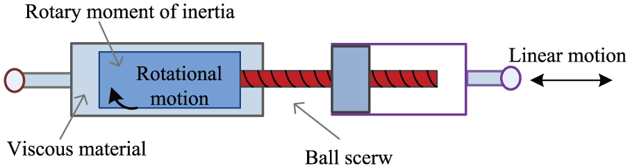
The basic schematic diagram of RID is shown in Figure 1. The detailed configuration will not be given here as different RIDs can be described in the same mechanism. From Figure 1, we can see that a linear motion is transformed to rotational movement due to the ball screw; meanwhile, the small linear displacement is amplified so that more energy from the system can be dissipated in the viscous material with a relatively small damping coefficient.
RID model.
An RID can be represented as shown in Figure 2 and the force applied to it can be determined using the following expression

where
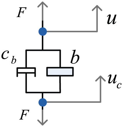
Simplified model of RID.
The force–deformation curves in Figure 3 show the hysteretic behavior of viscous, inertia, and rotational inertia dampers. It can be seen that the RID has the characteristics of general viscous damper and pseudo-negative stiffness caused by inertia.
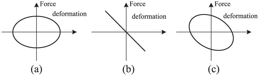
Force–deformation relation: (a) viscous damper, (b) inertia damper, and (c) rotational inertia damper.
Modeling of the outrigger system with RID
A new outrigger system with RID can be developed considering the attractive characteristics of RIDs. Figure 4(a) presents a simplified model of a high-rise building with the proposed system and an equivalent model in which the outrigger system is represented by a rotational spring (Figure 5). The RIDs are symmetrically equipped in the outriggers. Assume that the bending stiffness of the outrigger is infinite and the length of each outrigger is r. The bending stiffness of the core is EI and m represents the mass per unit length of the core. EcAc is the axial stiffness of the peripheral column, H is the length of the core, and
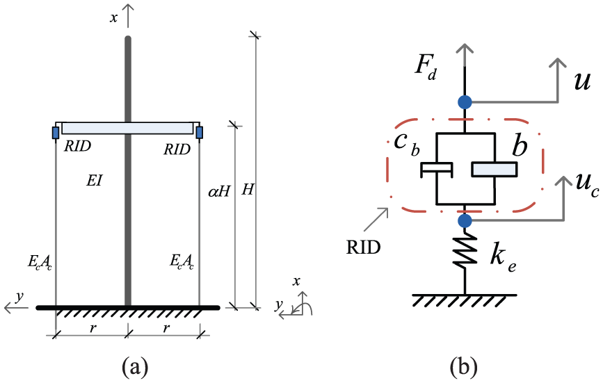
Model of a building with an RID outrigger system: (a) simplified model and (b) simplified model of RID with peripheral column.
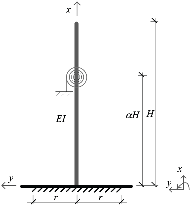
Equivalent model of a building with an RID outrigger system.
As ignoring deformation of the exterior columns in the analysis of the outrigger system may result in numerical errors (Tan et al., 2014), the peripheral columns will be included in the models in this study. A mechanical model of the RID with a peripheral column is presented in Figure 4(b), where the model is drawn in fuchsia dot-dash line box. Then, the governing equation of this model can be expressed as
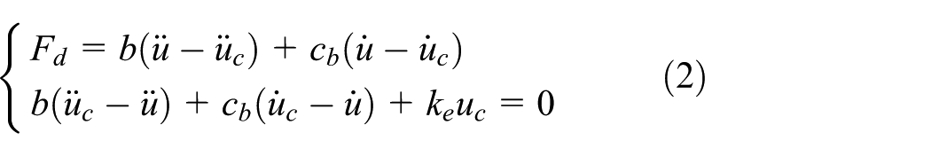
where
With Laplace transform, equation (2) can be expressed as

where
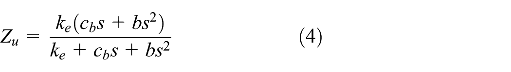
with

where
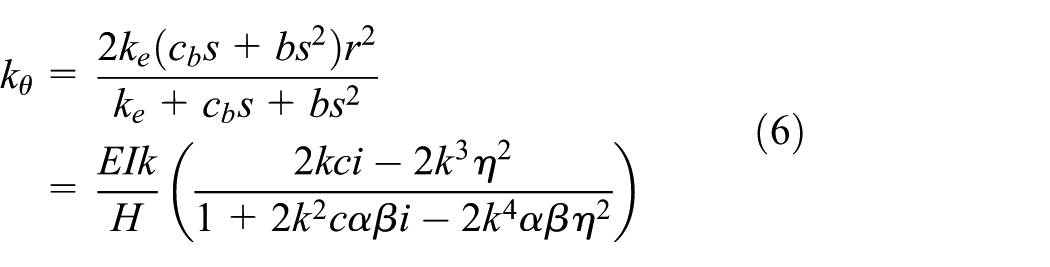
where

with
Thus, with the equivalent model shown in Figure 5, the new outrigger system can be analyzed.
Dynamic characteristics of the RID outrigger system
Dynamic equation formulation
The motion equation of a vibrating Bernoulli–Euler beam with no damping can be expressed as
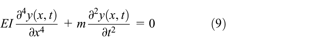
where

Nondimensionalizing by

The general solution of equation (11) can be expressed as
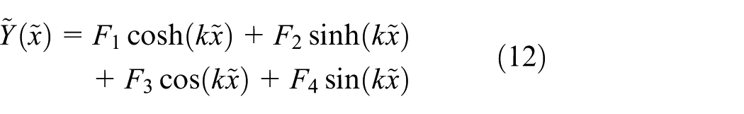
where
In this study, only one pair of RID outriggers is used, and therefore the cantilever beam shown in Figure 4(a) is divided into two segments, with the lower part as the first segment. Let the solutions for the segments be expressed as
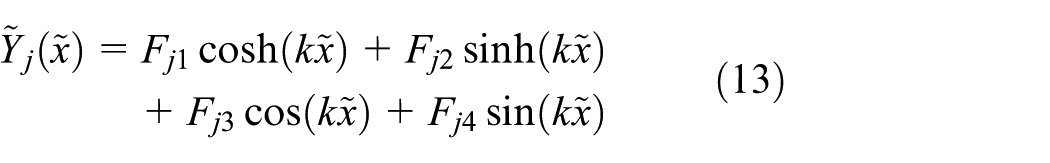
where

where the superscripts “–” and “+” of
where


with


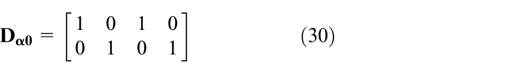
The boundary conditions for the fixed end of the left of the first segment, namely
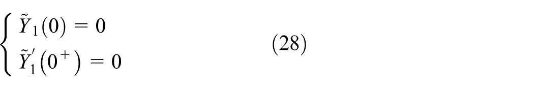
substituting equation (13) into which yields

where
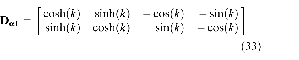
The boundary conditions for the free end of the right of the second segment
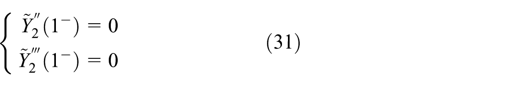
substituting equation (13) into which yields

where
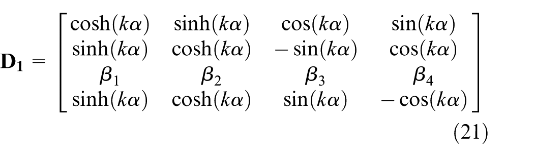
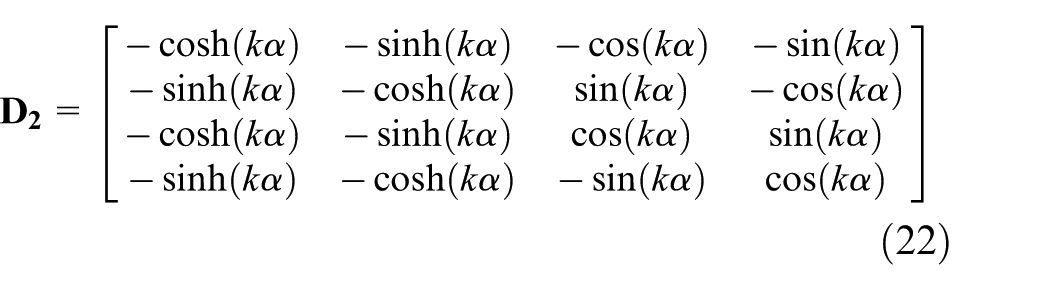
Integrating equations (18), (29), and (32) into a characteristic equation, one can get

where
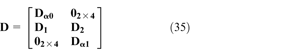
To obtain the nontrivial solution for equation (34), the determinant of the coefficient matrix must vanish

After rearrangement of equation (37), a new equation is obtained as follows
When
However, if the axial stiffness of the column is simultaneously viewed as infinite, like
Equation (40) is the characteristic equation of the structure with damped outriggers (Chen et al., 2010). Based on equation (38), the complex frequency of the RID outrigger system can be expressed in the following form
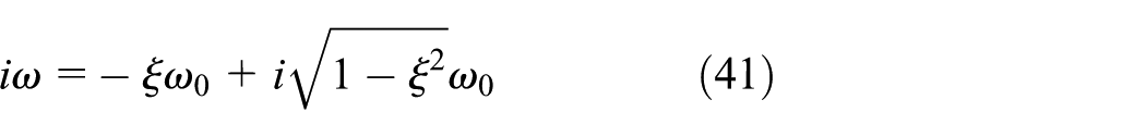
where

Dynamic characteristic analysis
Structural safety is commonly related to dynamic characteristics. In order to avoid or reduce unwanted vibration, it is common practice to keep the natural frequencies of the structure away from the dominant frequency for earthquake. One of the other methods is to enhance the structural damping ratio. The use of the RID outrigger system belongs to the latter.
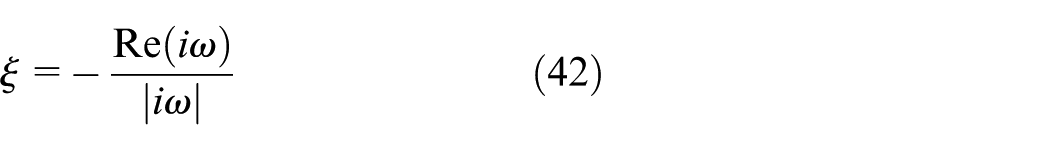
In order to verify the proposed analysis method, Figure 6 shows the comparisons between the finite element method (FEM) and the analysis method with
Comparisons between the FEM method and the analysis method
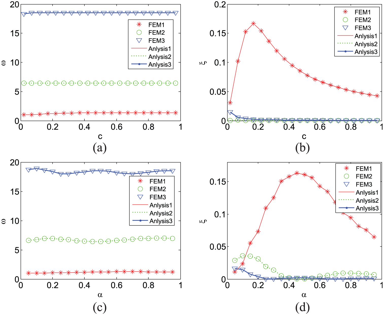
The position of the RID outriggers influences the performance for structure vibration attenuation. Figure 7 illustrates the changes of modal frequency ratios and modal damping ratios with the damping parameter c when RID is installed at 0.55 H. It is to be noted that, as similar conclusions can be drawn when RID is installed at other positions, the corresponding results will not be presented here. Figure 7(a), (c), and (e) shows the pseudo-undamped natural frequency ratio of the RID outrigger system in the first, second, and third modes, respectively, where
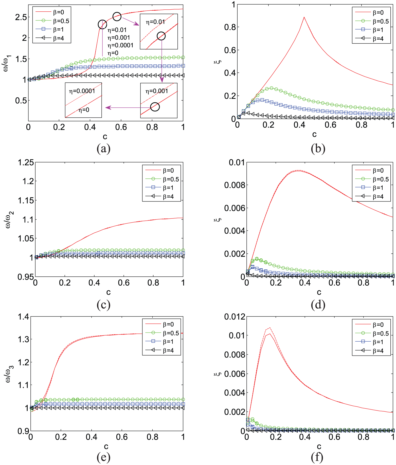
The first three frequency ratios and damping ratios for
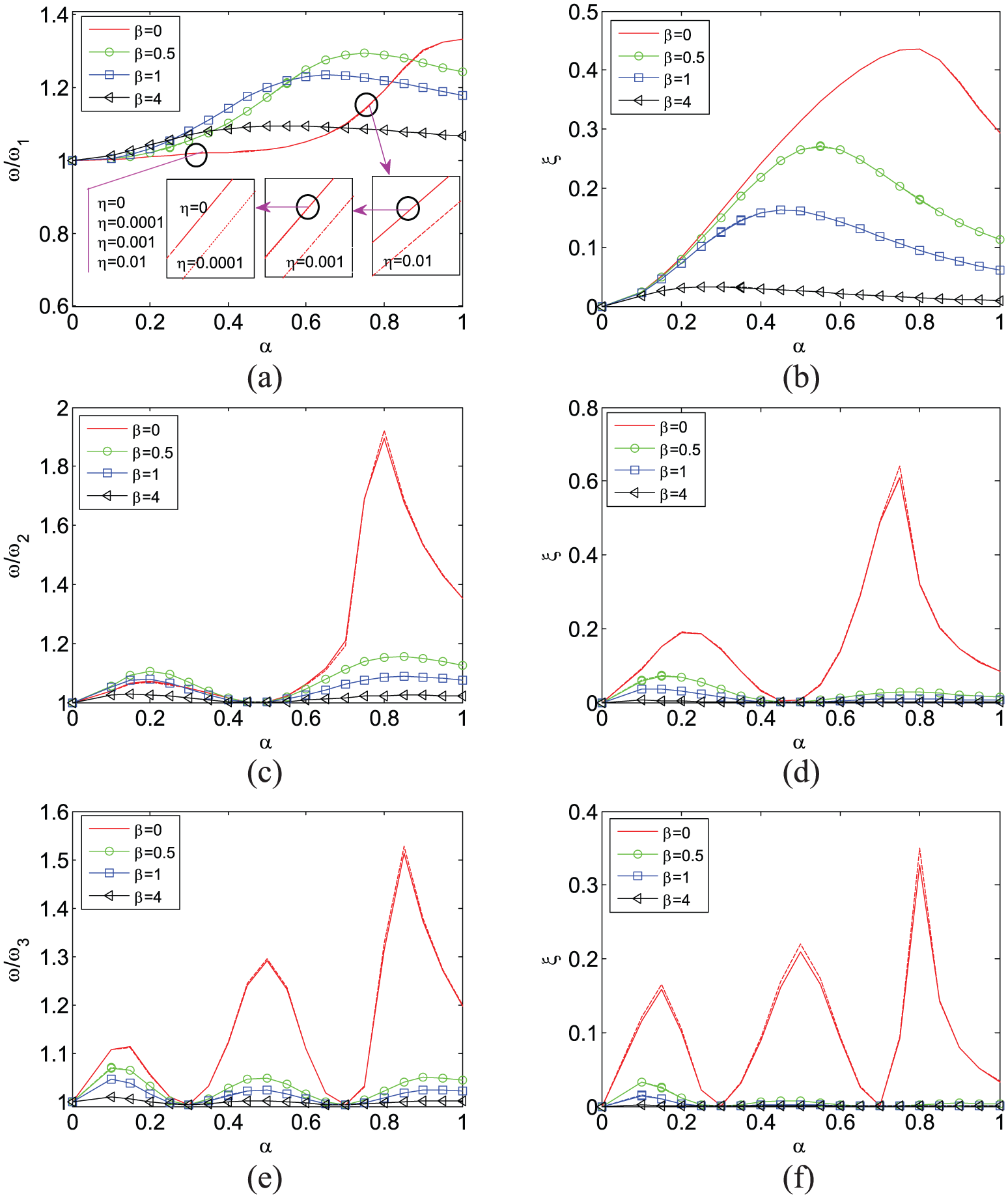
The first three frequency ratios and damping ratios for
Figure 7(b), (d), and (f) presents the modal damping ratios varying with the damping parameter
Further detailed information about the pseudo-undamped natural frequency ratios and modal damping ratios versus the position parameter
FEM
To determine the response of the outrigger structure with RID under seismic excitations, FEM is utilized. The dynamic equation for the system can be expressed as

where
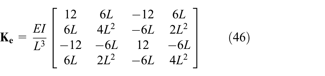
The high-rise building is modeled by conventional Bernoulli–Euler beam element. The mass matrix for one element can be written as
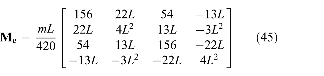
where
The inertial force caused by earthquake on one element is given by
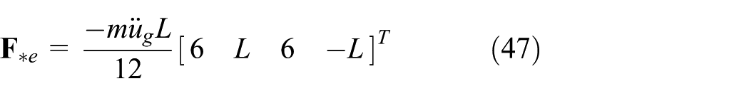
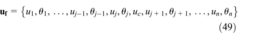
Assume that the building is modeled with n beam elements and the displacement vector contains displacements for nodes

Furthermore, assume that the RID outrigger is installed at node j. The displacement
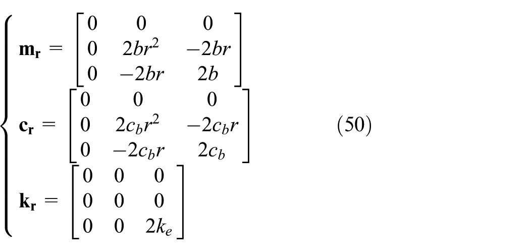
The contributions of the outrigger to the global matrices will be
By assembling the beam elements using the above equations, one can obtain the dynamic equation for the whole system

where
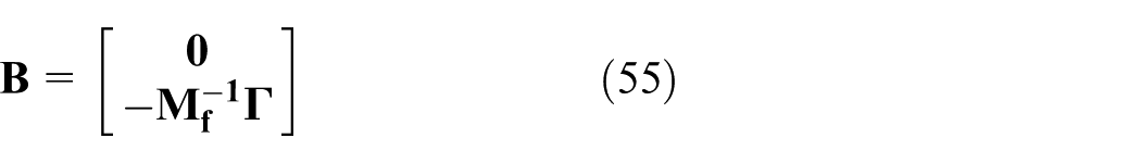
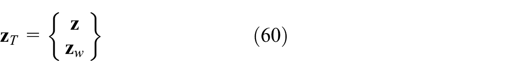
Introducing the state variable in
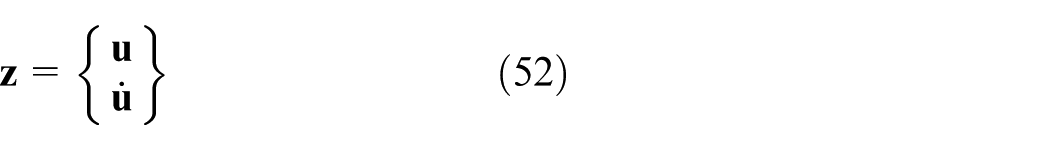
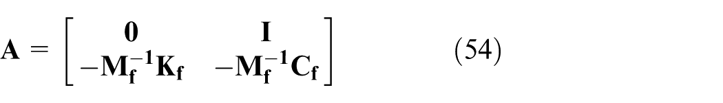
equation (52) can be written in the following form

where
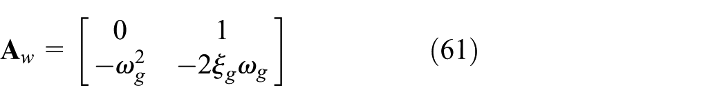
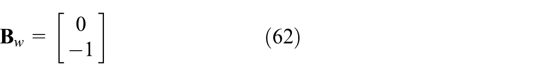
In this study, the Kanai–Tajimi filtered white noise ground motion model (Housner, 1955), which is utilized to obtain the optimum parameters, can be characterized by the following form
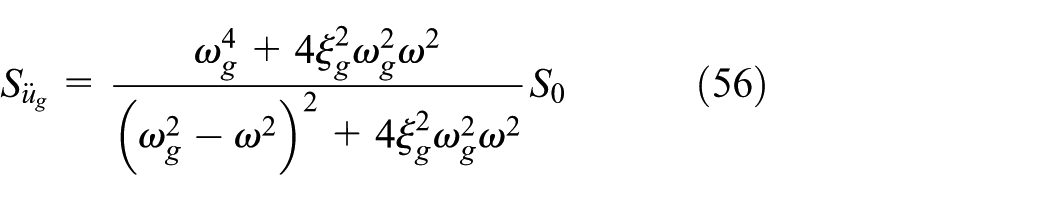
where

where
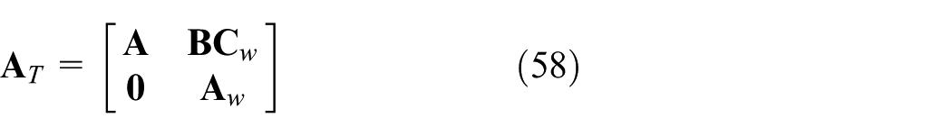
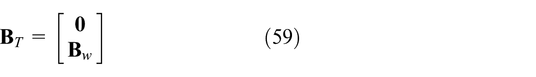
Let
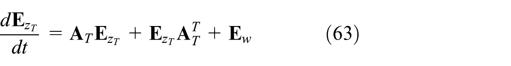
For the stationary response of the structure subjected to stationary random excitation, equation (63) reduces to a simpler form

Therefore, the mean square response can be determined by solving the last equation.
Simulation analysis
A numerical example for the RID outrigger system is provided to investigate its parameters and performance of the seismic mitigation. The main model parameters are as follows:
Figure 9 illustrates the displacement variance at the top of the structure versus
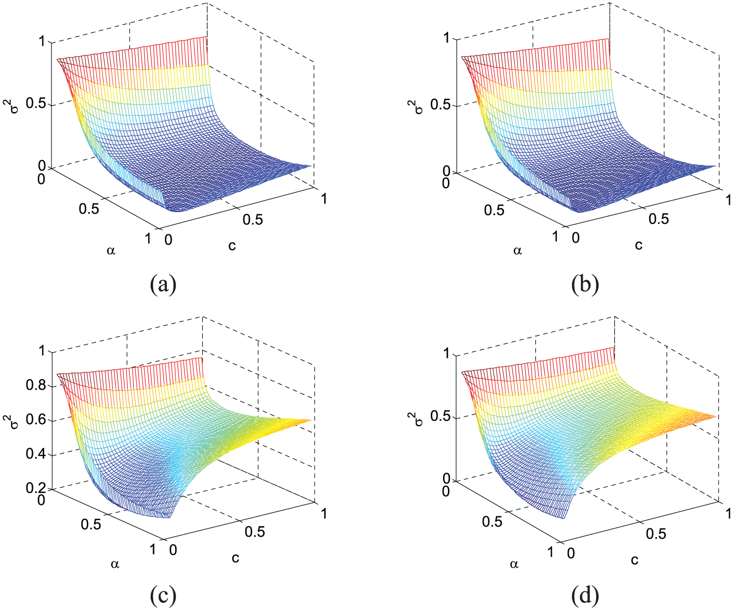
Top displacement variance versus
Figure 10 shows the optimal position parameter
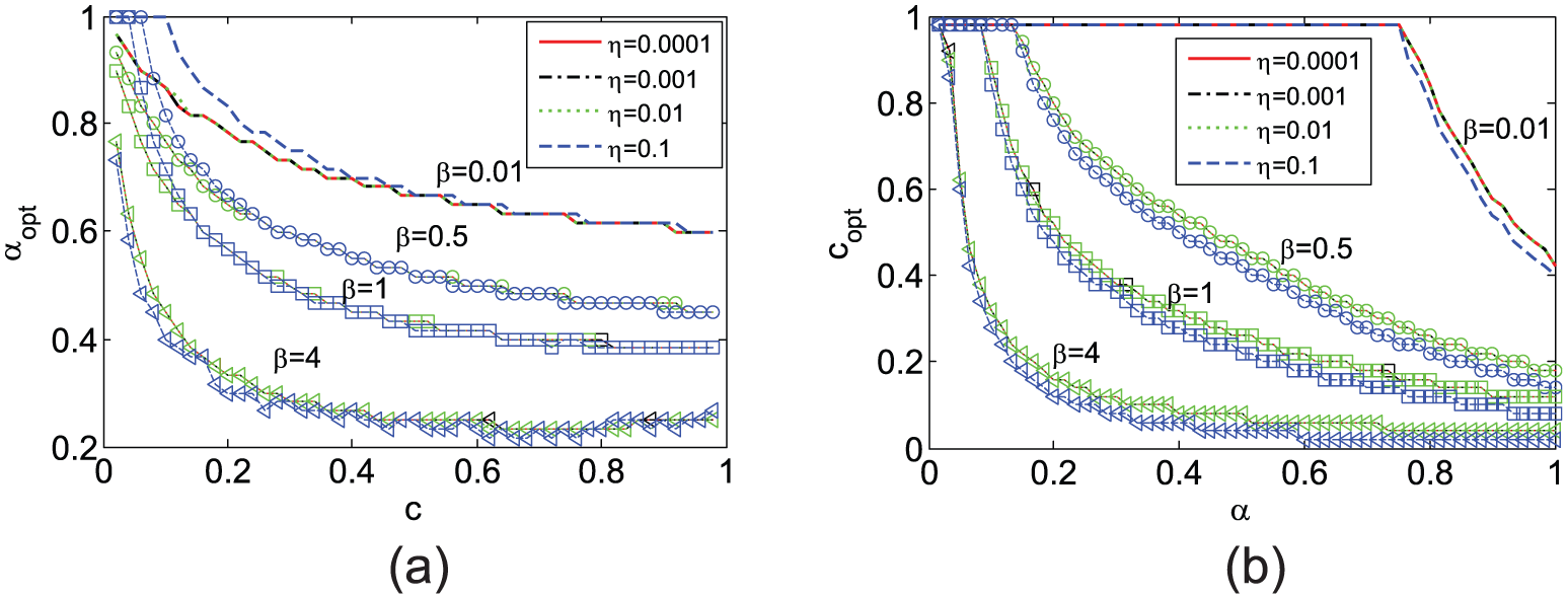
Optimum parameters: (a)
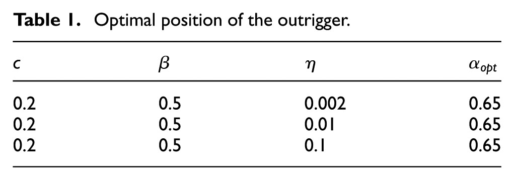
Two typical seismic records are applied to investigate the performance of the RID outrigger system. The two records are for the North and South component of El Centro earthquake in 1940 and Kobe earthquake in 1995, both of which are adjusted to the maximum ground acceleration of 3 m/s2. The known parameters of the RID are listed in Table 1 and the corresponding optimal position
Optimal position of the outrigger.
Mass parameters.
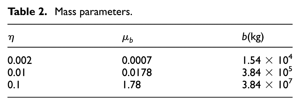
From Table 2, one can observe that
The responses at the top of the structure under earthquake excitations for
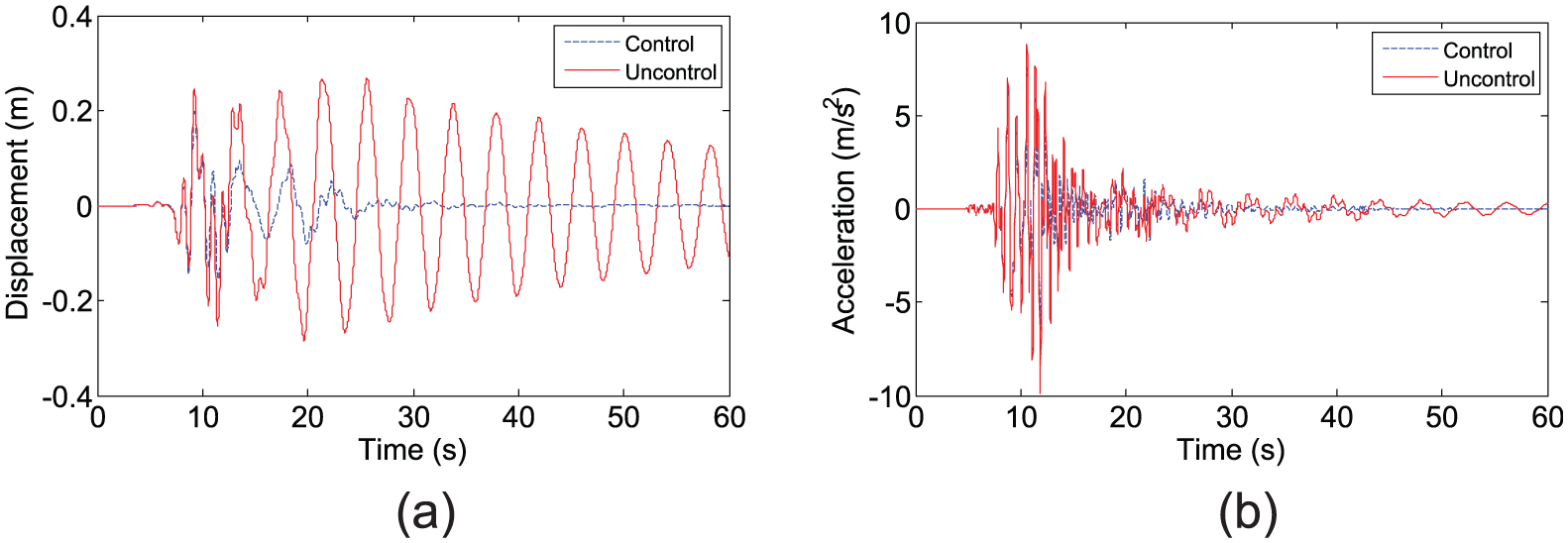
Response under Kobe excitation: (a) displacement and (b) absolute acceleration.
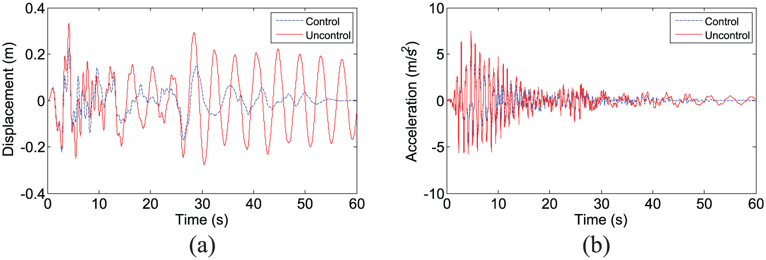
Response under El Centro excitation: (a) displacement and (b) absolute acceleration.
The above analysis results indicate that the use of RID is effective for suppressing the vibration. Figure 13 presents the force–displacement relationship of the structure with RID outriggers subjected to El Centro excitation. Curves for the total equivalent force of RID and just damping force are included. Note that the total equivalent force includes both damping force and inertial force caused by RID. It can easily be found that, for the two cases of
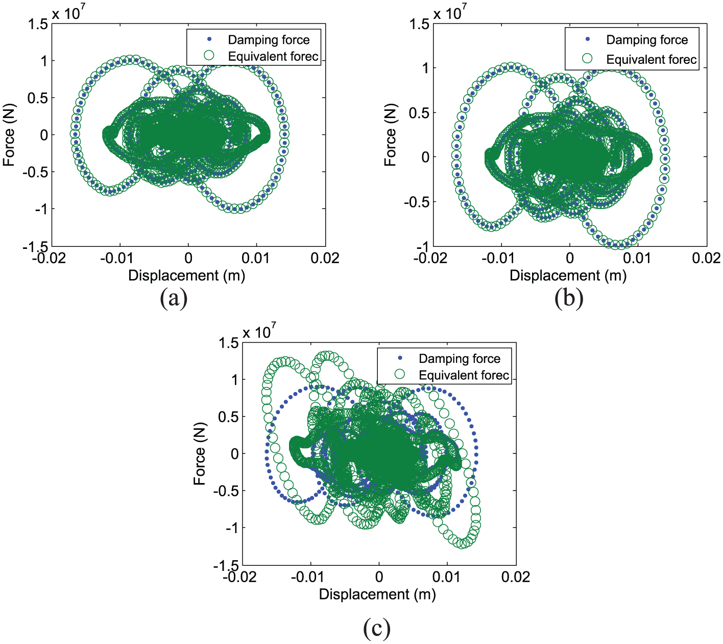
Force–deformation relationship for El Centro excitation: (a)
Conclusion
RID was introduced into the outrigger system to suppress excessive vibrations of high-rise buildings. Based on Bernoulli–Euler beam theory, an equivalent analysis model was proposed to simulate the structure with an RID outrigger. The dynamic characteristic equation of the damped system was derived using numerical assembly technique, and the influence of the RID on the first three modes was investigated. Finite element analysis was also conducted on seismic responses of the high-rise building model to investigate the performance of the new outrigger system. The following conclusions can be drawn:
The use of an RID outrigger in high-rise buildings can be effective for earthquake mitigation. Numerical simulation shows that the RID outrigger system has an excellent control performance. The reductions in peak responses are 70.42% in displacement and 80.82% in acceleration for Kobe wave, and 67.59% in displacement and 90.10% in acceleration for El Centro wave.
The relative bending stiffness of the peripheral columns has a significant influence on the pseudo-undamped natural frequency ratios and modal damping ratios of the structure, while the mass parameter of RID has little effect. The optimal outrigger positions for maximum modal damping ratios are different for different modes, and the optimal position for one mode may not be appropriate for another mode. A global analysis of the structure subjected to the filtered white noise earthquake excitation has been conducted and it has been found that
The damping force in RID is predominant and the inertial force is insignificant. It may have significant influence on the damped system for larger
Generally, the detailed research considering bending stiffness and shear stiffness should be further conducted to provide a complete understanding.
Footnotes
Declaration of Conflicting Interests
The author(s) declared no potential conflicts of interest with respect to the research, authorship, and/or publication of this article.
Funding
The author(s) disclosed receipt of the following financial support for the research, authorship, and/or publication of this article: This work was supported by the Program for Changjiang Scholars and Innovative Research Team in University (Grant No. IRT13057) and the National Natural Science Foundation of China (Grant No. 51478129), and also in part by Guangdong Special Program (Grant No. 2014TX01C141) and Yangcheng Scholars Program (Grant No. 1201541630)