
Abstract
This article presents experimental testing results designed to obtain physical and mechanical properties of glued laminated bamboo (glubam) beams. Two types of glubam beams made with different pre-processed plybamboo boards were tested. One type glubam beam specimens were made with thin layer bamboo strips of about 2 mm thick, and the other were manufactured with thick layer bamboo strips of about 5–6 mm. Test results of the full-scale beams show that the behavior of the glubam beams was elasto-brittle, similar to typical wood-based glulam. The different configurations of bamboo strips have certain influence on the flexural performance of glubam beams, and the mean ultimate capacity of the samples with bamboo strips flatwise is higher than that of edgewise. Based on the experimental results reported herein, the strength capacity equations are proposed for calculating the flexural rigidity and strength capacities of the glubam beams.
Introduction
Bamboo is a kind of natural material, which has the characteristics of fast growing, low energy consumption (Xiao et al., 2008, 2009), and low carbon emission during the process of production (Xiao et al., 2013) and is promising material, suitable for green and sustainable construction. In East Asia, South America, and other regions rich in bamboo resource, people have a long tradition of using round bamboo for structuring buildings and bridges (Archila-Santos et al., 2012). However, due to the hollow tubular structure, round bamboo is easy to split under load, and the reliability of round bamboo connection is much weaker than corresponding timber one. The relatively small diameter also hinders the large cross-sectional components often needed in structures, limiting the applications of bamboo in construction. Bamboo was also used in reinforcing concrete, as the substitute of steel bars, when there was a shortage of steel or in buildings required to have reduced magnetic shielding (Ghavami et al., 1995, 2005; Saucier and Smith, 1967; Terai and Minami, 2011; Xu et al., 2013). However, from structural point of view, such need is greatly reduced following the advancement of steel industry and the availability of fiber-reinforced polymer (FRP).
From 1980s, following the advancement of modern timber industry, products of bamboo based on glue lamination started to appear in construction industry. Plybamboo boards became widely produced and available in the later 1990s in China, as the substitute of plywood and were mainly used for concrete formwork, and later as floorings for trucks or container boxes. The process of manufacturing so-called thin layer plybamboo boards starts with splitting the bamboo culms into 20–30 mm wide and approximately 2-mm-thick strips by a manual process or machines (Xiao et al., 2013). The strips have to be boiled and then dried to reduce the organic contents. The strips are then netted into curtains with all the strips aligned in the same orientation. The netted bamboo strip curtains are cleaned for the dust removal and dried in a kiln to reach the moisture content of about 18% and then saturated in phenol formaldehyde resin. The resin-saturated curtains are dried again and stored with good ventilation keeping the moisture content to be approximately below 15%. Layers of resin saturated bamboo strip curtains are stacked in parallel or orthogonally to reach the thickness of about 10–30 mm, which is related to its final loading capacity. Finally, the stacked bamboo layers were pressed at a pressure of 20 MPa under a temperature of about 150°C, for about 15 min, using a procedure similar to manufacturing plywood. The typical plenary dimensions of the glubam boards are 1220 mm wide and 2440 mm long.
With the development of bamboo industry in China, another laminated bamboo product is formed by pressure gluing accurately shaped bamboo strips with section of about 5–8-mm-thick and about 20 mm wide under elevated temperature since 2000s (Sharma et al., 2015). The original products were mainly used for floorings to replace hardwood floorings. The thicker strip–based laminated bamboo can also be manufactured as structural lumbers and for such reason, are also named as laminated bamboo lumber (LBL; Tang et al., 2014; Tian, 2013).
The last author’s research team has been working on the development of glued laminated bamboo or glubam and has designed and built several demonstration buildings and bridges (Xiao et al., 2008, 2009, 2010, 2013). Glubam is made with a two-step pressing process. The first step is the production of structure-use plybamboo boards with hot-pressing process. The second step is a pressing process under room temperature around 20°C, also known as cold pressing, in which the plybamboo are sized into specific dimension according to design need and then glued under pressure into the required structural elements, as the example shown in Figure 2. To make an analogy with steel structures: the first step of making glubam is the plybamboo production, like the rolling of steel plates or sheets, while the second step is similar to the forming of specific structural elements based on the design requirements, using procedures like cutting and joining for steel structure. Compared with the hot-pressing process–based LBL, the advantage of glubam is its relative cost-effectiveness, because the transportation of the plates and sheets produced in the first step process is more efficient and the second step of the cold-pressing process can be easily established, using similar equipment like those for producing timber-based glulam. This article reports the experimental studies on large-scale beams made of two types of pre-processed glubam boards within thick or thin layer bamboo strips.
Experimental program
Glubam materials
Glubam is a kind of two-step pressure glued LBL, with the second process similar to wood-based glulam (Xiao et al., 2008, 2009, 2010, 2013). Glubam beam is manufactured by gluing together layers of elements cut from plybamboo boards. For long-span glubam beams, the plybamboo boards with limited length need to be lengthened during cold-pressing procedure, usually, using finger-jointing technique.
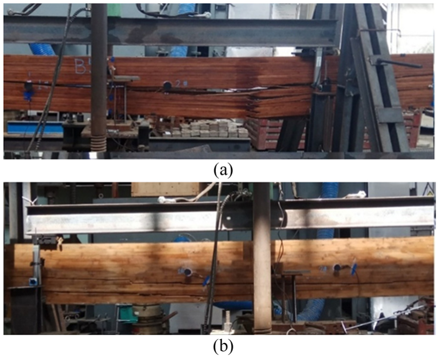
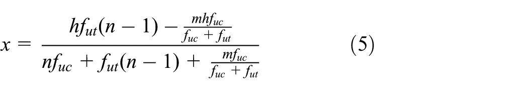
According to the different thicknesses of bamboo strips, plybamboo board can be divided into two types in this research: thick strip plybamboo board laminated by bamboo strips of about 5 mm thick, shown in Figure 1(a) and thin strip plybamboo board laminated by bamboo strips of about 2 mm, shown in Figure 1(b). In this research, thick plybamboo boards were carbonized to fit the requirements for out-door structural elements. The direction of the strips in thick strip plybamboo is normally all along longitudinal direction, while the configuration of strips in thin strip plybamboo is more complicated, the ratio of longitudinal grains and transverse grains is typically 4:1, for the applications in glubam beams or columns (Xiao et al., 2013). A workpiece coordinator system is established, where its x-axis represents the main fiber direction (100% fiber for the thick strip panel and 80% fiber for the thin strip panel), it’s y-axis represents the less-fiber direction (0% for the thick strip panel and 20% for the thin strip panel), and its z-axis represents the thickness or glue surface direction.
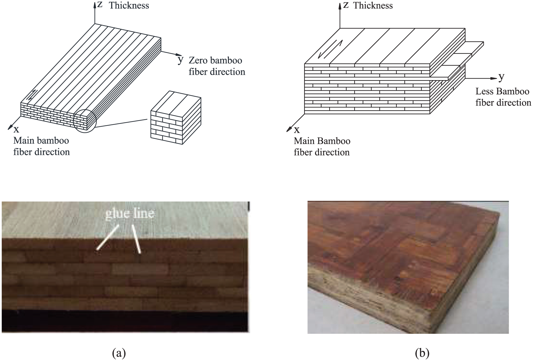
(a) Glubam made with thick bamboo strips and (b) glubam made from thin bamboo strips.
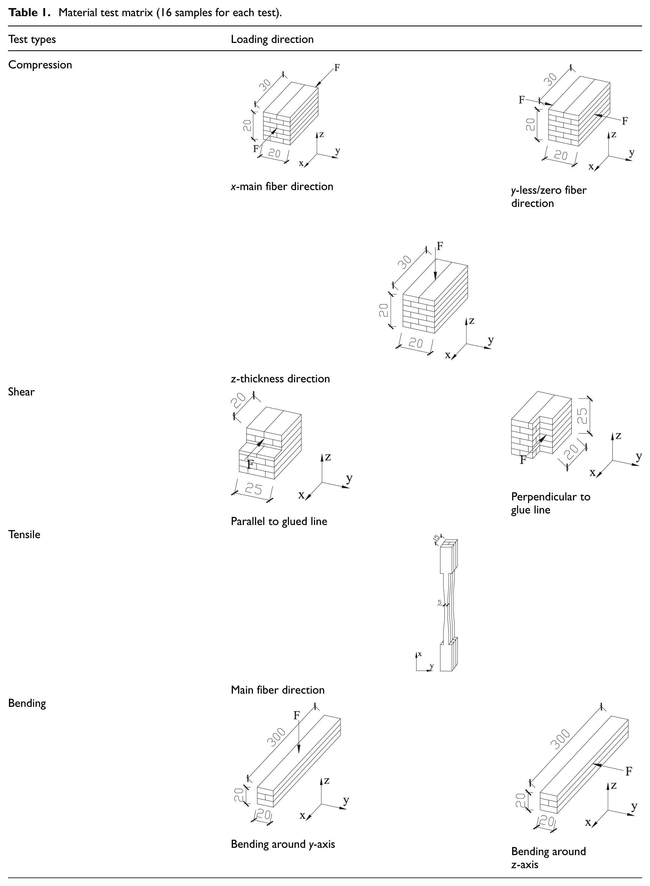
Since there is currently no standards or specifications for testing glubam, the studies of the material properties of glubam are based on specifications for timber materials. Table 1 lists the information of specimens for each type of test. All specimens were taken from glubam beams to be subjected to bending tests and they were measured with digital caliper. Before test, the specimens were preserved in environmental chamber for 15 days with a constant temperature of 20°C and relative humidity of 55%. The samples were made in accordance with Physical and Mechanical Tests of Wood (GB/T 1928-2009:2009, 2009) and ASTM D143-14:2014 (2014). Test load was applied by universal testing machine.
Material test matrix (16 samples for each test).
The material test results of the two types of plybamboo boards are presented in Tables 2 and 3, respectively. For glubam with thick bamboo strips, the average compression strengths under three different loading directions were 25 MPa for
Mechanical properties of glubam with thick bamboo strips (in MPa, MC = 9.8%).
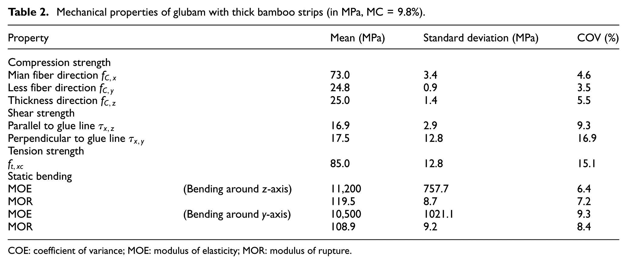
COE: coefficient of variance; MOE: modulus of elasticity; MOR: modulus of rupture.
Mechanical properties of glubam with thin strips (Xiao et al. 2013).
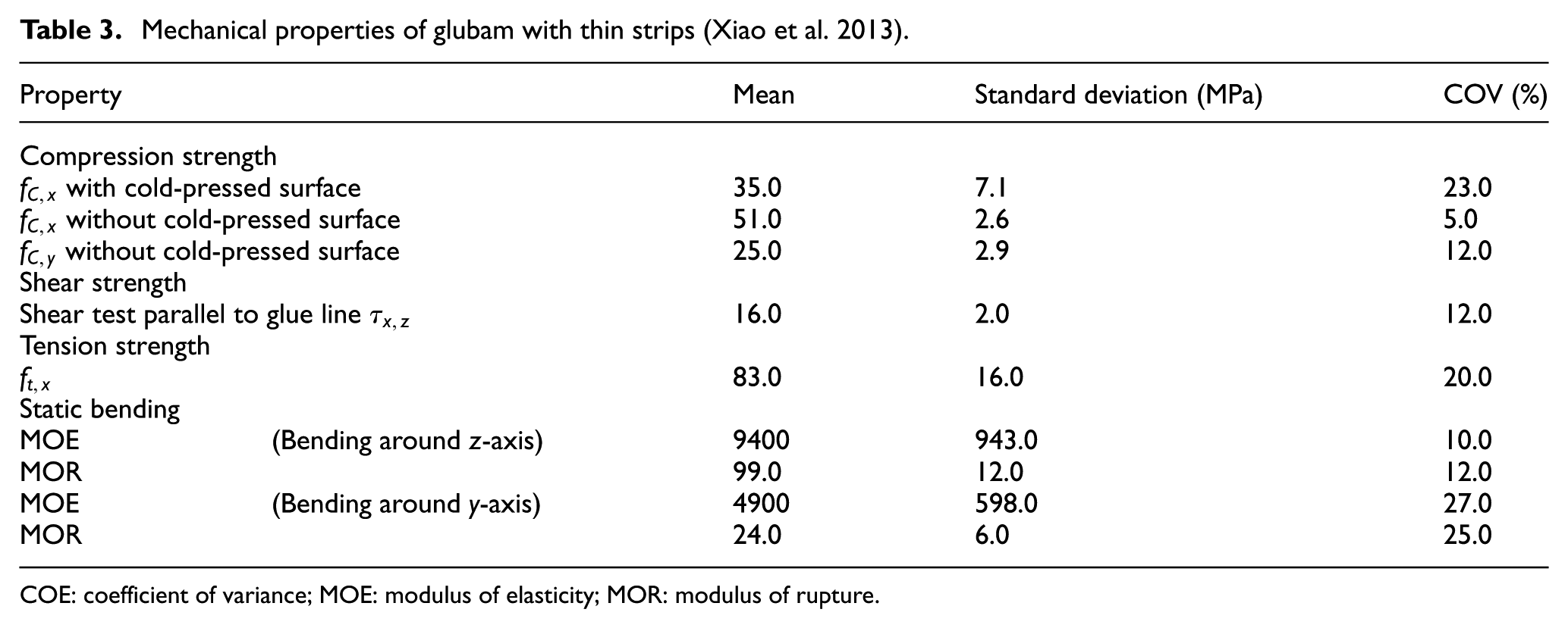
COE: coefficient of variance; MOE: modulus of elasticity; MOR: modulus of rupture.
Glubam beams
The glubam beam specimens were made by pressure laminating elements cut from plybamboo boards at room temperature around 20°C. Because all the beam specimens were longer than the length of the original plybamboo boards (less than 2.4 m), it was necessary to lengthen the elements cut from the plybamboo using finger joints. In order to reduce the impact on flexural capacity of glubam beam, finger joints were not arranged at mid-span, where the moment is the largest. In this research, the shortest distance between finger joint and mid-span was 1.5 m, and the length of fingers was 100 mm, as shown in Figure 2(a) and (b). To obtain glubam beams with specific dimension, the plybamboo boards, after cutting teeth, were numbered according to the staking sequence requirements. Then following the principle of bottom-up, two-part epoxy adhesive was applied at the finger joints and gluing surface. When all plybamboo boards were assembled, pressure was applied using hydraulic pressure, as shown in Figure 2(c). The pressure was kept for 24 h for curing of the adhesive. The thicknesses of plybamboo board for GB-I and GB-II are 20 and 28 mm, respectively.
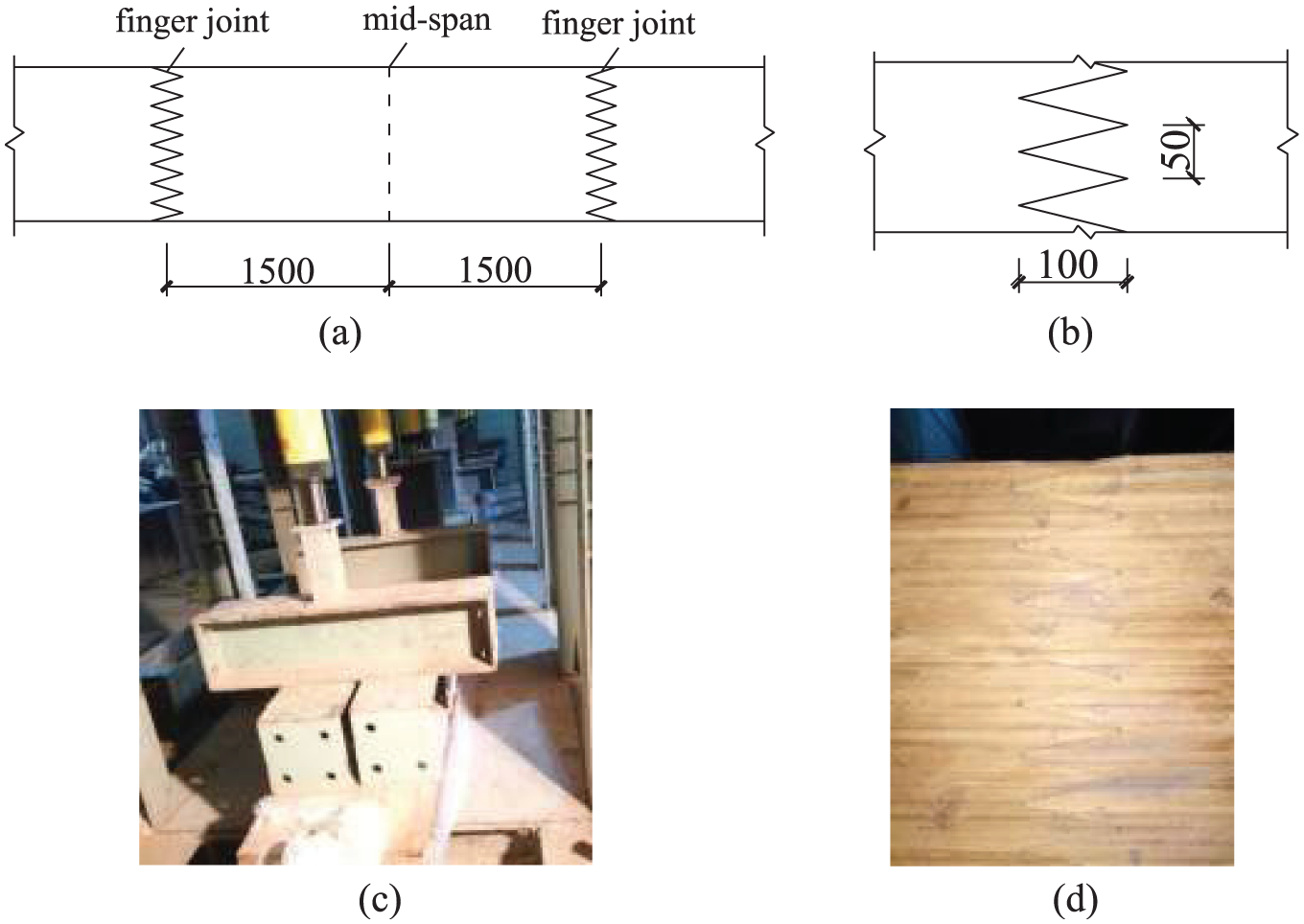
Manufacture of glubam beam: (a) finger joint position, (b) details of finger joint, (c) glubam beam under pressure, and (d) finger joint of glubam beam.
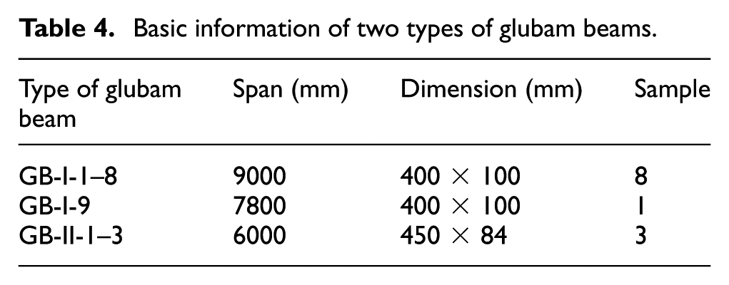
The basic information of glubam beams with thick strip plybamboo board (GB-I) and glubam beams with thin strip plybamboo board (GB-II) are presented in Table 4. The cross-section of GB-I, including GB-I-1 to GB-I-9, is 100 mm×400 mm. The span of GB-I-1 to GB-I-8 is 9.0 m whereas 7.8 m of GB-1-9. The cross-section of GB-II, including GB-II-1 to GB-II-3, is 84 mm × 450 mm with the span of 6.0 m. In order to obtain an experimental understanding of the influence of bamboo strips’ organization (figure 3) on the mechanical performance of glubam beams, two types of thick strips plybamboo boards with were applied to manufacture GB-I samples. Plybamboo boards with bamboo strips flatwise including GB-I-1 to GB-I-4 and edgewise of GB-I-5 to GB-I-9.
Basic information of two types of glubam beams.
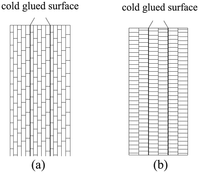
Cross-section of two types of glubam beams: (a) bamboo strips flatwise and (b) bamboo strips edgewise.
Test setup and instrumentation
All specimens were tested at room temperature of (25 ± 5)°C, and relative humidity was (55 ± 10)%. According to Test Standard for Wood Structure (GB/T 50329-2012:2012, 2012), four-point loading system was adopt and six displacement transducers were installed at the position of loading points, mid-span and supports, as shown in Figure 4. Strain gauges were arranged evenly along the height of the specimen at mid-span. Four pairs of lateral supports were arranged along the length of the specimen to prevent out-of-plane deformation of the specimen during the test. The deflection and strain data were collected by the DH3816 data acquisition instrument. After the specimen was fixed, three preload processes were carried out to eliminate the possible initial errors of equipment. At the beginning of the test, load was kept at 7 kN per step and remained for 5 min in order to obtain stable deformation data. When visible cracks appeared at the bottom of specimen, load per step decreased to 3.5 kN until the termination of the loading due to specimen failure.
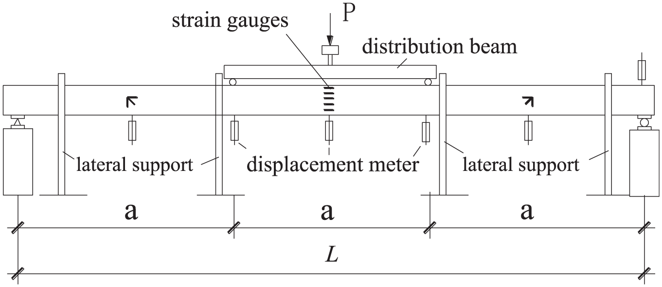
Loading setup.
Experimental results and discussions
General observations
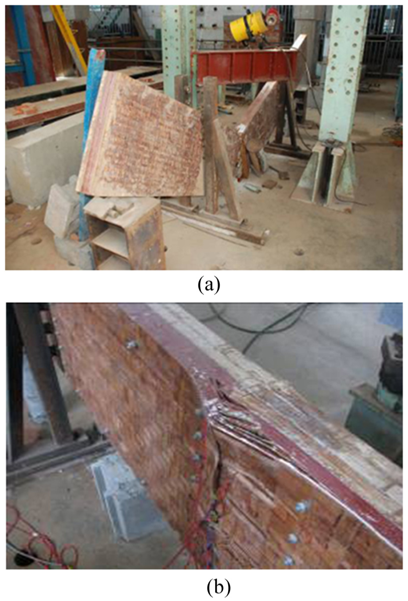
For tests of GB-I, the failure mode of the nine specimens was elasto-brittle. At the early stage of loading, the deflection of mid-span progressed steadily with the increase of the load, and no deterioration detected. When load reached 45 kN, cracks first appeared at finger joints closest to the mid-span and developed quickly. When the load exceeded 60 kN, the finger joint closest to the mid-span fractured in the tension zone, followed by further increase of deflection. After 2–3 steps of load, the specimen broke down in a short period of time and was accompanied with loud sounds. The failure of GB-I-1 toGB-I-4 was all tensile failure, as seen in Figure 5(a). Among the five specimens GB-I-5 to GB-I-9, three were tensile failure and the other two were inter-laminar shear failure in tension zone, as shown in Figure 5(b). For the specimens with bamboo strips edgewise, the internal adhesive surfaces of the plybamboo boards cannot be effectively staggered, and they are easy to peel off at tension zone before bamboo fibers reach their ultimate tensile stress, which lead to the failure of the specimens.
Failure patterns for GB-I: (a) tensile failure and (b) tensile failure along with inter-laminar shear failure.
For GB-II, the failure process of GB-II-1 and GB-II-3 was similar, when load increased to about 50 kN, the finger joints in tension zone started to loosen followed by cracking sounds; however, the bending stiffness did not decline significantly. When load increased to 90 kN, vertical cracks appeared and developed quickly, with load increased to the point that the grains at the bottom of the tensile zone in middle span was pulled off, and the entire specimens failed suddenly, as shown in Figure 6(a). For GB-II-2, the deformation of middle span at the initial stage of the test was relatively stable, but delamination of glue surface at beam’s compression zone was noticed when the recorded load reached 45 kN. After load came to about 85 kN, the load increased slowly but the deflection in mid-span increased steadily, until the out-of-plane bulging of the layers of bamboo strips in the compression zone, as shown in Figure 6(b).
Failure patterns of GB-II specimens: (a) tensile failure and (b) compression failure.
Comparing the two types of glubam beam specimens, the failure types of GB-I were significantly different from that of GB-II. Two main failure types of GB-I were observed, as presented in Figure 5. Six specimens exhibited tensile failure followed by cracking along the longitudinal axis of the beams, as shown in Figure 5(a), and the rest were horizontal shear failure along the beam axis in tension zone, as exhibited in Figure 5(b). Horizontal shear cracking was considered due to the lack of bamboo fibers in the vertical direction perpendicular to the beam axis. For GB-II, since there are 20% of the bamboo strips arranged in the vertical direction perpendicular to the beam axis, horizontal shear cracking is prevented, and the failure was caused by bending failure of the cross-sections near the mid-span region, as shown in Figure 6.
Load and deflection relationships
The load–mid-span deflection curves of GB-I and GB-II specimens are shown in Figure 7(a) and (b), respectively. At the beginning stage, the slops of load-deflection curves of the GB-I specimens are almost the same, and there are no obvious plastic deformations before failure. The load–deflection curves of the specimens in the GB-II series are similar to that of GB-I specimens. Comparing to GB-II-1, and GB-II-3, specimen GB-II-2 had a lower load carrying capacity, indicating the influence of different failure patterns.
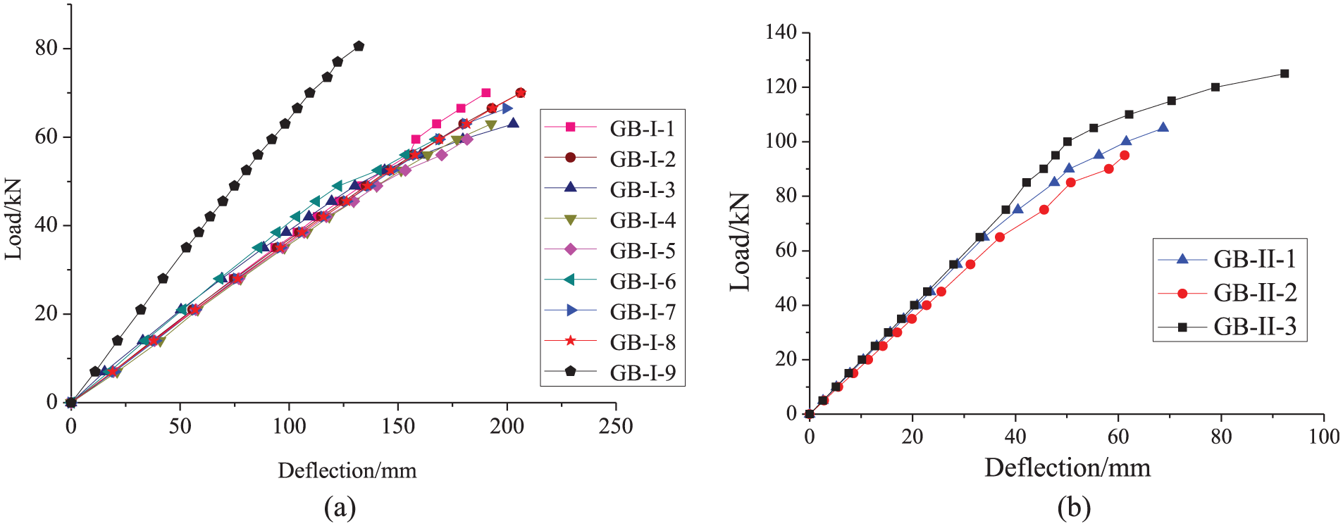
Load versus mid-span deflection relationships: (a) GB-I beam specimens and (b) GB-II specimens.
Strain development in glubam beams
Examples of mid-span strain distributions of the glubam beam specimens are exhibited in Figure 8(a) and (b) for GB-I and GB-II specimens, respectively. As shown in Figure 8, all the strains essentially grow proportionally corresponding to the increase of load until the ultimate capacity. This is another indication that the glubam beams behaved in a linear fashion. The maximum strains detected from the beam specimens are all smaller than the reported ultimate strain from the material tests, Li et al. (2015), indicating that at the failure of the glubam beams, the material strengths have not been exhausted.
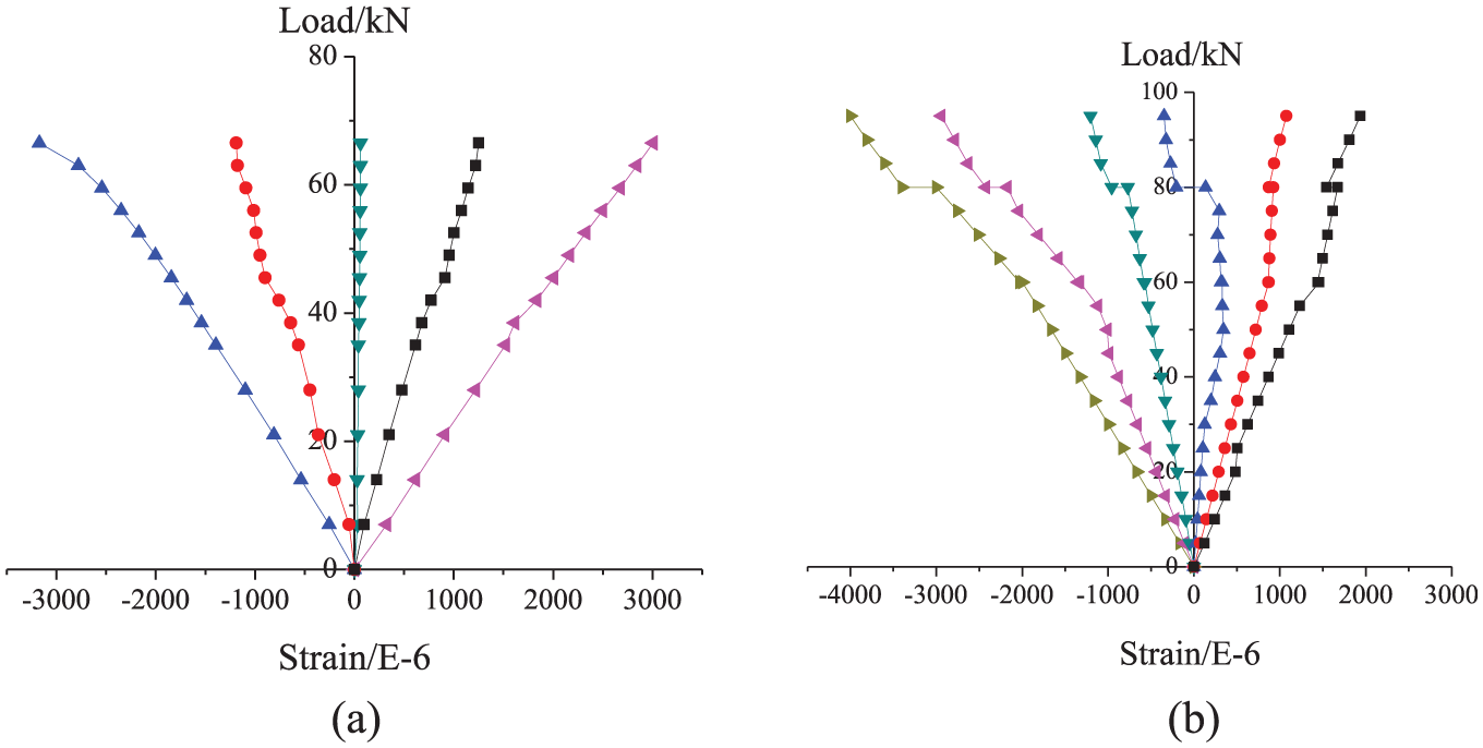
Examples of stress distributions: (a) GB-I-1 and (b) GB-II-2.
Estimation on ultimate capacities
Analysis of test results
Main test results of the two kinds of glubam beams are listed in Table 5. Average ultimate load of GB I 1-4 glued with flatwise strips (fig. 3a) was 68.6 kN; in comparison, the corresponding load of GB I 5-8 glued with edgewise strips (fig. 3b) was 64.5 kN. This indicates that manufacturing glubam beam by applying plybamboo board with bamboo strips flatwise is more reasonable. The deflection limit capacity of GB-I, according to Code for design of timber structures (GB 50005-2003:2005, 2005), is about 20% of the ultimate bearing capacity and 45% of GB-II. Therefore, the stiffness can be used as a design indicator of glubam beam.
Main test results.
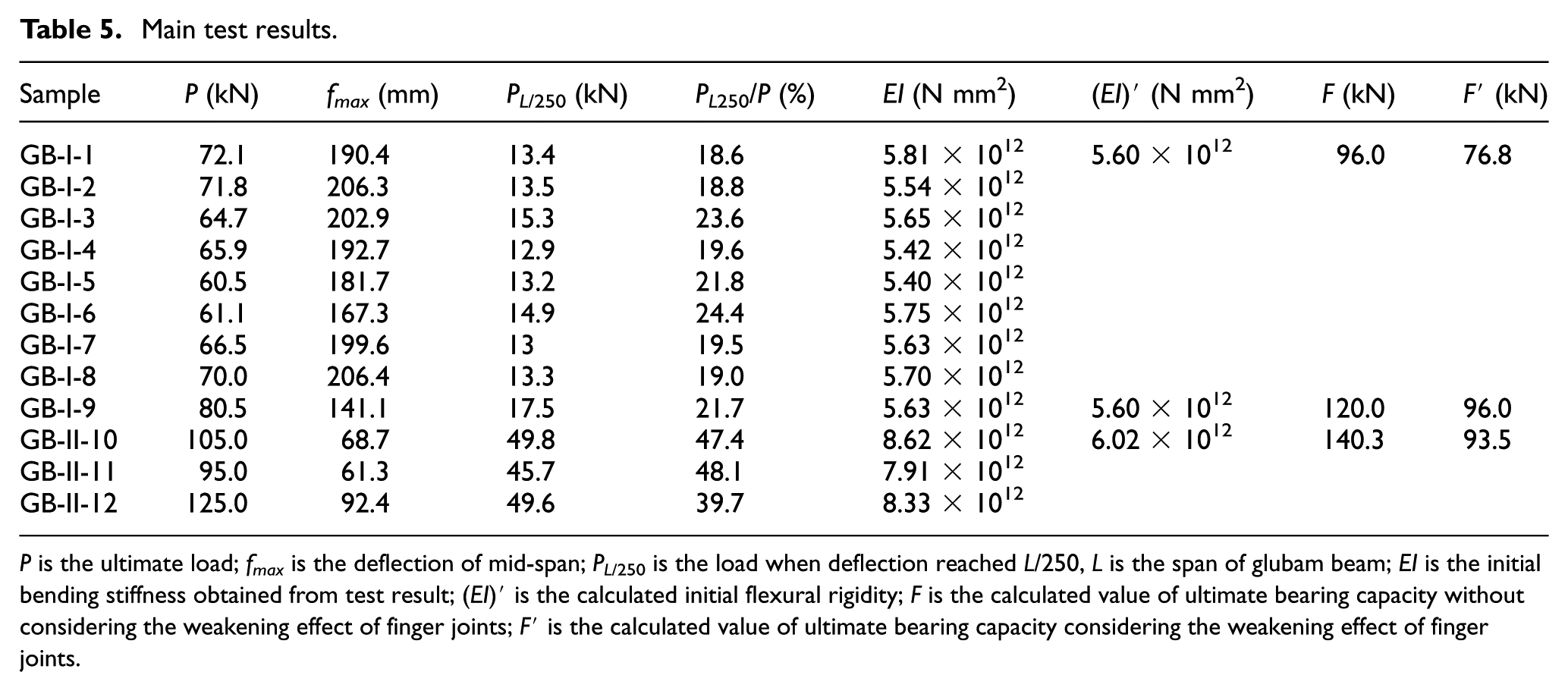
P is the ultimate load; fmax is the deflection of mid-span; PL/250 is the load when deflection reached L/250, L is the span of glubam beam; EI is the initial bending stiffness obtained from test result; (EI)′ is the calculated initial flexural rigidity; F is the calculated value of ultimate bearing capacity without considering the weakening effect of finger joints; F′ is the calculated value of ultimate bearing capacity considering the weakening effect of finger joints.
Influence of finger joint on bending stiffness and ultimate capacity
The flexural rigidity (EI) of glubam beam within elastic limit can be calculated as follows
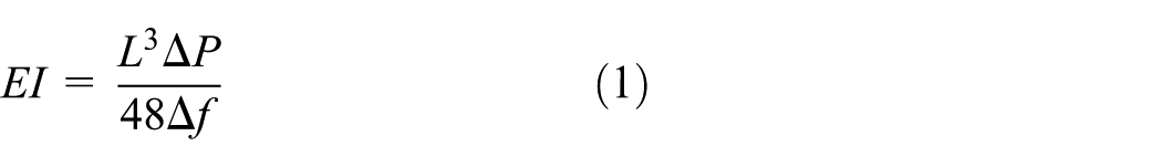
where L is the span of the beam, ΔP is the increment of load at the elastic stage, and Δf is the deflection of the middle span under ΔP.
Since the related calculation parameters are taken from the initial loading stage, the specimens are still in elastic deformation stage; thus, the adverse effects of finger joints are not taken into consideration while calculating the value of EI, as shown in Table 5. The mean test value of initial flexural rigidity of GB-I and GB-II specimens are 5.61×10¹² and 8.29×10¹² N mm2, respectively. The elastic modulus of GB-I is 10.5 and 9.4 GPa of GB-II. The calculated values of initial flexural rigidity of GB-I and GB-II based on the full section are 5.46 × 10¹² and 6.02 × 10¹² N mm2, respectively. The ratio of test value to calculated value of GB-I is 1.03 and 1.38 of GB-II, indicating that the finger joints do not have much influence on the initial flexural rigidity of glubam beams.
In accordance with code for design of timber structures (GB 50005-2003:2005, 2005), the flexural strength of rectangular cross-section timber beam can be calculated as follows
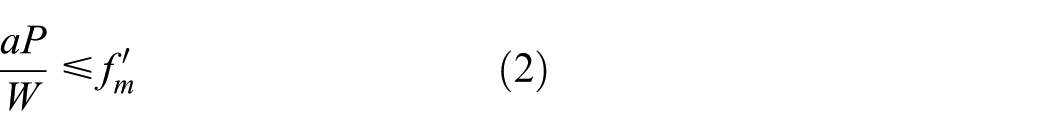
where a is the distance between loading support and loading point, P is the ultimate load, W is the section modulus, and
In view of the fact that the destruction of the finger joint occurred before the failure of beam, thus the structural resistance of finger joint at broken cross-section was ignored while calculating the flexural bearing capacity design value of glubam beam specimen. From the results presented in Table 5, it is concluded that finger joints have a significant influence on the bending capacity of bamboo beams, and its weakening effect depends on the thickness of the plybamboo board.
Calculation of flexural properties
Glubam is not a homogeneous material. When glubam beams were manufactured from bamboo strips, there are both natural bamboo material and adhesives inside. If totally solidified, the shear strength and ductility of adhesive are much lower than that of natural bamboo material. In the course of stress, the adhesive does not conform to the deformation of natural bamboo. Although the area of glue lines is only a small proportion of the whole cross-section, it may have a certain adverse effect on the flexural performance of glubam beam, especially for the specimens with bamboo strips edgewise. Test results have proved that the influence is relatively small and if the differences of the mechanical property between adhesive and bamboo are considered, it will involve more complicated stress analysis. In order to obtain a simplified calculation model, the bending performance of glubam beam is derived based on the assumption of a homogeneous material, and the difference in structural resistance between finger joints and non-finger joints is taken into consideration.
In order to estimate the load bearing capacity of glubam beam, a simplified tension and compression stress-strain bilinear constitutive model of bamboo used in glubam beam (Murat et al., 2018; Wei et al., 2017; Zhou et al., 2016) is given in Figure 9, where a, b, and c represent the ultimate tensile strain, proportional limit, and ultimate compressive strain of bamboo, respectively. For glubam beams with finger joints, the structural resistant capacity at finger joints is mainly the adhesive bond strength, the mechanical interaction between the fingers, and the friction between fingers. At the initial stage of loading, the finger joints are reliable and no cracks appear, when tensile stress in tension zone exceeds their structural resistance, cracks start to appear and develop rapidly along the longitudinal direction of the beam.
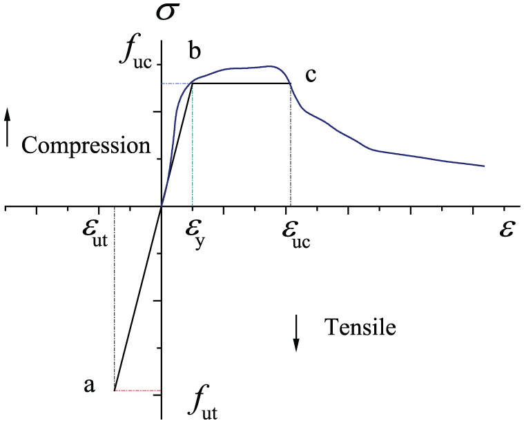
Simplified stress–strain curve of glubam.
When a glubam beam reaches its critical failure point, finger joints at tension zone exit to work completely, while finger joints at compression zone are compressed and can still function. When calculating the flexural load capacity of glubam beam, the difference in stress distribution of finger joints should be taken into consideration. It is assumed that at critical stage, the finger joints in tension zone completely lose bearing capacity while those in compression zone continue to exert resistance. A glubam beam can be considered to have n layers of plybamboo boards glued together and each with thickness of t. It is reasonable to assume that failure of a glubam beam only occurs at the section with finger joints for one layer of plybamboo board. At failure, the tension zone of the finger-jointed layer looses resistance whereas the rest of the section is still working. The cross-section of glubam beam and the strain distribution in the cross-section at failure stage are shown in Figure 10. The internal equilibrium equation of moment can be obtained as follows

where x is the yield height of compression zone, x′ is the non-yield height of compression zone, and hy is the height of tension zone.
And
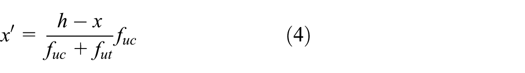
Then
where
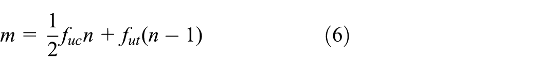
Strain distribution of cross-section in finger joint.
The bending moment can be obtained by integrating the two sides of equation (4) along y direction
Table 6 shows the comparison of calculated values and test values of flexural bearing capacity of specimens. Obviously, the maximum error between the calculated value and the test value of GB-I is −19.1%, and the minimum error of −3.6%. For GB-II, the maximum and minimum errors are −26.4% and −3.2%, respectively.
Comparison of test values and calculated values of ultimate capacity.
Conclusion
In this research, the mechanical properties of two types of glubam (glued laminated bamboo) are obtained. They are shown to possess same or even higher average strength than many engineered wood. Cold-pressed surface has significant influence on the compression strength of glubam manufactured by thin strip plybamboo board. Properties of glubam parallel to and perpendicular to strips are different. The tension and compression strength parallel to grain are much higher than that of perpendicular to grain.
The bending capacity of two types of full-scale glubam beams with finger joints was tested in this study. The results show that the failure of glubam beams was elasto-brittle. For both the thick strip–based glubam beam series GB-I and the thin strip–based glubam beam series GB-II, the influence of bamboo strip configuration on flexural performance of glubam beam was tested and the mean ultimate capacity of the samples with bamboo strips flatwise is higher than that of edgewise. The deflection limit of GB-I and GB-II beams were respectively 20% and 45% of the ultimate bearing capacities. Finger joints exhibit to have little influence on the initial stiffness but significantly reduced the ultimate bearing capacities of glubam beams. The results obtained by a simplified calculation method can be considered to be in accordance with the average bearing capacity of the two types of glubam beam.
The study demonstrates that glubam beams have good potential for structural applications. However, further research is still needed, especially the influence of cold glue lines and its corresponding quantified calculations, etc.
Footnotes
Acknowledgements
The authors would like to acknowledge the supports of the Thousand-talent National Expert Scholarships provided by the Nanjing Tech University, and the Jiangsu provincial Double Innovation scholarship. The glubam materials described in this article were manufactured by the Advanced Bamboo and Timber Technologies (ABTT) Ltd.
Declaration of Conflicting Interests
The author(s) declared no potential conflicts of interest with respect to the research, authorship, and/or publication of this article.
Funding
The author(s) disclosed receipt of the following financial support for the research, authorship, and/or publication of this article: Thousand-talent National Expert Scholarships provided by the Nanjing Tech University, and the Jiangsu provincial Double Innovation scholarship.