
Abstract
Welded hollow spherical joint is an extremely widely used connection pattern in space lattice structures. Understanding the behavior of the welded hollow spherical joint after elevated-temperature exposure is critical for the fire damage assessment of the entire space lattice structures. In this study, both experimental and numerical studies were conducted to reveal the mechanical behavior of eccentrically loaded welded hollow spherical joints subjected to eccentric loads after cooling from three elevated temperatures up to 1000°C, wherein two different methods were considered, namely, air and water cooling. Associate mechanical performance, such as load versus longitudinal displacement and load versus steel tube rotation responses, initial stiffness, load-bearing capacities, and strain development, were obtained and further analyzed. The results showed that the behavior of welded hollow spherical joints began to change when the exposure temperatures exceeded 600°C, with obvious reductions in both stiffness and strength. In addition, the influences of different cooling methods were significant. The joints cooled by water generally presented higher load-bearing capacities than those cooled by air. Furthermore, three-dimensional finite element analysis was conducted via ABAQUS software. After validating the finite element model against experimental results, parametric studies were performed and a practical formula was proposed to calculate the load-bearing capacity of welded hollow spherical joints subjected to eccentric load after elevated-temperature exposure.
Keywords
Introduction
Welded hollow spherical joint was initially developed by Prof. X. L. Liu in 1966 and first applied in the Science & Technology Hall in Tianjin, China (Liu, 2000). It possesses such advantages as high stiffness, light weight, simple in construction, easy to connect, and absence of node eccentricity. At present, welded hollow spherical joints have been developed as one of the most widely used connection patterns for space lattice structures. Fire is one of the main disasters that may cause severe damage to building structures. However, given that the space lattice structures are commonly conservatively designed hence bear considerable redundancy and the load-bearing members are usually with proper fire proof, the whole structure may not collapse during or after fire immediately. In that case, the post-fire safety evaluation of the structure is very necessary to determine the proper post-fire treatment. Hence, the behavior of the welded hollow spherical joints, which act as the key load-bearing connection elements, after elevated-temperature exposure must be investigated first to lay the foundation for the post-fire assessment of the whole structure.
The mechanical performances of welded hollow spherical joint at ambient temperatures without the consideration of temperature effects, such as the load-bearing capacity under both axial and eccentric load, initial axial stiffness, bending stiffness, and load–displacement model, have been extensively studied (Chen, 1990; Han et al., 2016; Han and Liu, 2004; Dong et al., 2005; Liao and Zhang, 2010; Tang, 2005; Wan, 1998; Wang et al., 2000). Furthermore, related design codes, such as JGJ 61-2003: Technical Specification for Latticed Shells and JGJ 7-2010: Technical Specification for Frame Structures, also provide recommendations for the design of welded hollow spherical joints. However, when it comes to the behavior of welded hollow spherical joints considering the temperature effects, few works could be found. Only the authors recently conducted relative studies focusing on their post-fire behavior subjected to axial load (Liu et al., 2017; Lu et al., 2018). As for the behavior under eccentric load, which is a more common force condition of welded hollow spherical joints in the real project, no research has been reported. With no doubt, further and deeper investigations are necessary.
In this article, the behavior of eccentrically loaded welded hollow spherical joints after elevated temperature exposure was studied. Eccentric and axial (for comparison) compressive tests were conducted on nine joint specimens after cooling from three preselected elevated temperatures up to 1000°C, wherein two different cooling methods, that is, air and water cooling, were considered. Associated mechanical behaviors, such as failure modes, load versus longitudinal displacement and load versus steel tube rotation responses, load-bearing capacities, and strain development, were obtained and further analyzed. Furthermore, three-dimensional (3D) finite element analysis (FEA) was performed via ABAQUS software and verified by the experimental results. Based on parametric studies, a practical formula was proposed to calculate the load-bearing capacity of welded hollow spherical joints subjected to eccentric loads after elevated temperature exposure.
Experimental investigation
Test specimens
Nine welded hollow spherical joint specimens, including seven eccentric compressive specimens and two axial compressive specimens (for comparison), were tested. The main parameters considered were exposure temperatures, cooling methods, and load eccentricity. Table 1 shows the details of the specimens, where D and t refer to the external diameter and thickness of the hollow sphere, respectively; d, L, and
Details of test specimens.
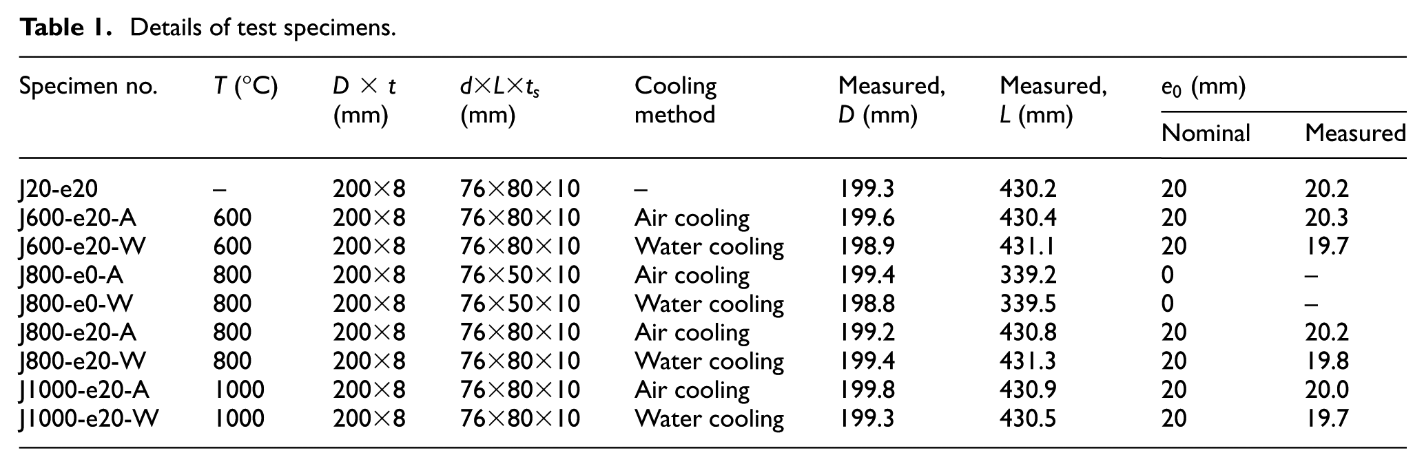
For all the specimens, the external diameter of the hollow sphere 200 mm, the thickness of the hollow sphere 8 mm, and the external diameter of the steel tube 76 mm were adopted. The dimensions selected are in accordance with the recommendations of both JGJ 61-2003 and JGJ 7-2010 and are widely used in the real engineering projects. Thickened steel tubes with a thickness of 10 mm were used for all specimens to ensure that the steel tubes do not fail before the hollow sphere; thus, the failure modes and load-bearing capacity of the hollow sphere can be obtained. According to JGJ 61-2003, the steel tube and the hollow sphere were butt welded and the quality of the weld meets the requirements of JG/T 11-2009: Welded Hollow Spherical Nodes of Space Grid Structures. Furthermore, the E50 welding rod, which is a commonly used welding rod grade for Q345 steel, was adopted. It is worth to be mentioned that the effect of welding induced residual stresses in the specimen was not discussed in this study because according to previous literatures (James, 2011; Wang et al., 2018), the welding process mainly affects the fatigue performance of the components and structures while has nearly no effect on the static performance like load-bearing capacity that was investigated in this article. An enlarged end plate with a thickness of 20 mm was welded to each end of the steel tubes. Specially, for the eccentric compressive specimen, two additional steel cushion blocks were welded to the end plates to exert the eccentric loads. The steel cushion block is with curvature; thus, the pinned end conditions can be achieved. Figure 1 presents the geometric details of the axial and eccentric compression test specimens, respectively.
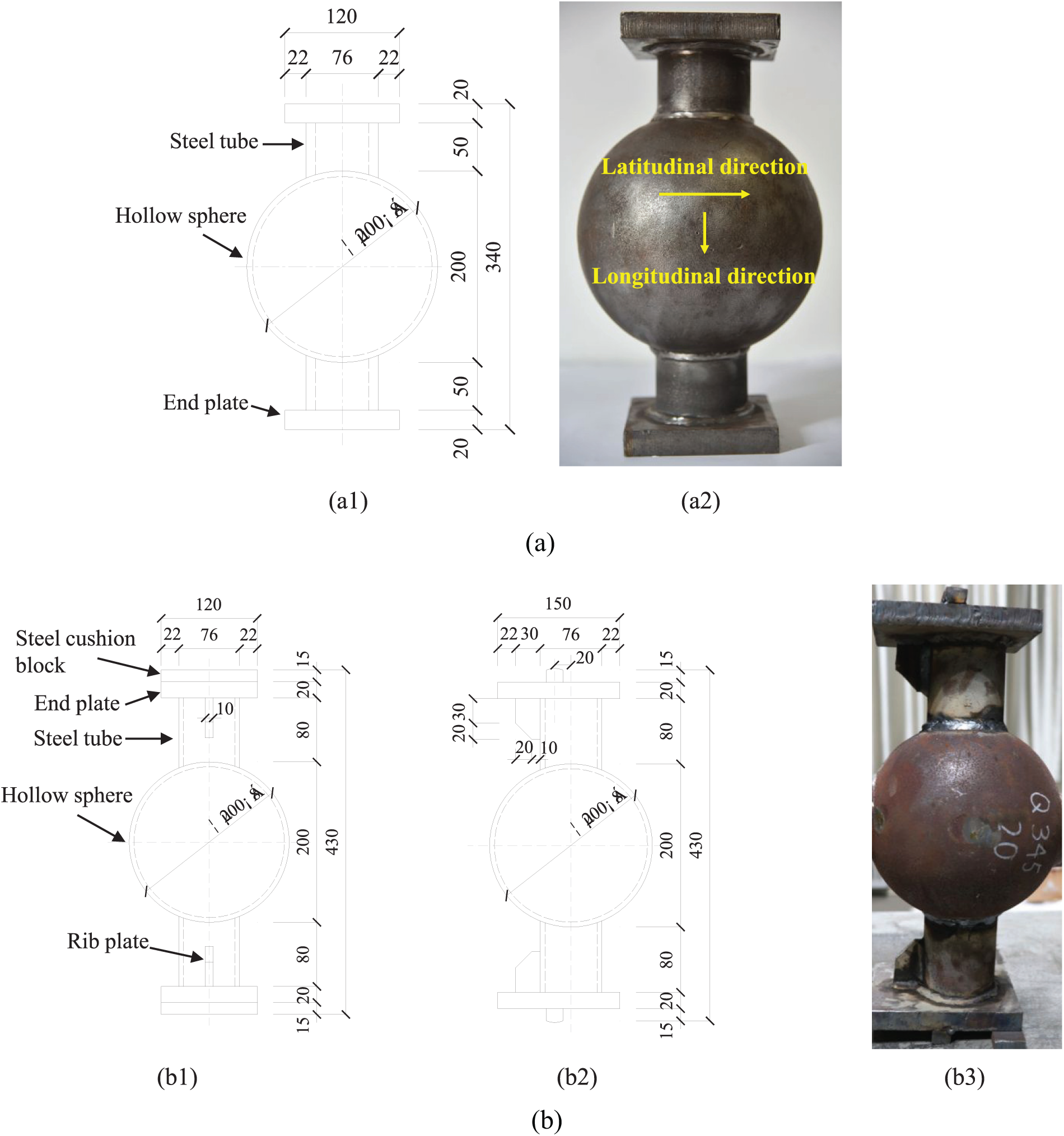
Test specimens. (a) Axial compression specimen: (a1) specimen details (mm) and (a2) specimen photograph. (b) Eccentric compression specimen: (b1) specimen details: front view (mm), (b2) specimen details: side view (mm), and (b3) specimen photograph.
Material properties
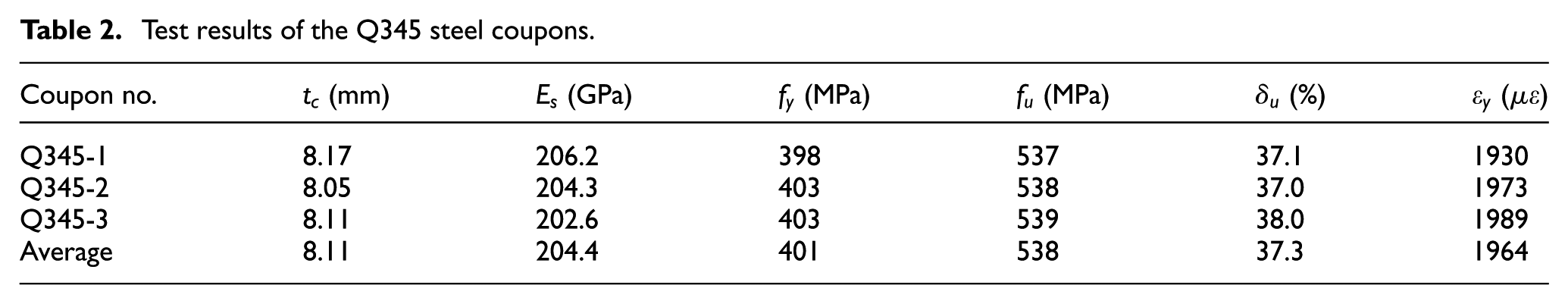
The structural steel used for all the joint specimens is Q345 hot-rolled steel, which is suggested by both the design codes JGJ61-2003 and JGJ7-2010. The quality of the steel is consistent with GB/T 1591-2008: High Strength Low Alloy Structural Steels. To determine the mechanical properties of the steel, tensile coupon tests were conducted on three Q345 standard coupons which were cut from the same batch of steel sheets used to manufacture the joint specimens. Both the geometry of the coupons and the loading method adopted meet the requirements of GB/T 228.1-2010: Metallic Material-tensile Testing. Part 1: Method of Test at Room Temperature. The test results are presented in Table 2, where
Test results of the Q345 steel coupons.
Test conditions and procedures
The experiment was conducted in two steps. First, the joint specimens were initially heated to the preselected elevated temperatures and then cooled down to ambient temperature. Subsequently, axial or eccentric compression tests were exerted on the joint specimens at ambient temperature. A temperature-controlled electric furnace was employed to heat the joint specimens. According to authors’ previous research (Liu et al., 2017), the behavior of welded hollow spherical joints almost unchanged when the exposure temperatures were under 600°C. Furthermore, the highest local temperature of a structure in a real fire may reach 800°C–1000°C. Hence, three elevated temperatures, namely, 600°C, 800°C, and 1000°C were selected herein. During heating, the furnace temperature was initially raised to a temperature which was 50°C lower than the target temperature at a rate of 10°C/min and then held for 10 min. Subsequently, the furnace temperature was raised to the target temperature at a rate of 5°C/min and maintained for another 30 min. By following such a heating process, a uniform temperature distribution of the joint specimen can be ensured and the exceeding of the target temperature can be prevented. After reaching the preselected temperatures, the specimens were removed from the furnace and cooled down to ambient temperature via two different methods, namely, air and water cooling. For air cooling method, the specimens were exposed to air and cooled down at their own rate to simulate the situation where a fire dies out naturally. While for water cooling method, the specimens were cooled down via water spraying using a water jet to simulate a situation where fire is extinguished by fire nozzles. The whole heating–cooling path is shown in Figure 2.
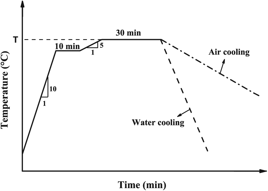
Whole heating–cooling path.
After elevated-temperature exposure, axial or eccentric compressive load was then exerted on each specimen via a 1000 kN electro-hydraulic servo material testing system until failure occurred, where the load decreased to 85% of the peak load. During the loading process, two linear varying displacement transducers (LVDTs), eight strain gauges, and eight strain rosettes were used to measure the longitudinal displacement and strain distributions of each axial compression specimen, while six LVDTs, eight strain gauges, and 12 strain rosettes were used to measure the longitudinal displacement, lateral displacement, and the strain distributions of each eccentric compressive specimen. The layouts of the measuring instruments used are shown in Figure 3.
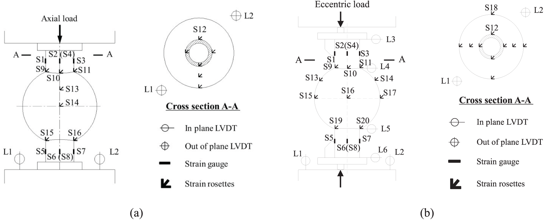
Layouts of the measuring instruments: (a) axial compression tests and (b) eccentric compression tests.
Experimental results and discussion
Failure modes
As shown in Figure 4, the failure modes of all the joint specimens can be characterized as a similar elastoplastic buckling collapse of the hollow sphere proposed by Han et al. (2004), regardless of the elevated temperatures exposed to and the cooling methods adopted. However, the buckling position was different for the joint specimens under eccentric and axial load. For eccentrically loaded specimens, the hollow sphere buckling was observed at the compressive side of the specimen, in the plane of bending moment applied, while under axial compression load, the hollow sphere buckling was observed at the zone around the steel tube. Furthermore, all joint specimens presented fairly ductile behavior with considerable deformation after reaching the ultimate loads, no matter whether or not they had been exposed to elevated temperatures. This characteristic indicates that high ductility can be kept for welded hollow spherical joints after fire exposure, which is positive for their post-fire reuse. In addition, in the cases of 800°C and 1000°C elevated-temperature exposure, a phenomenon with remarkable flaking of these oxide films was observed on the specimen surface due to the effects of both heating-cooling and loading.
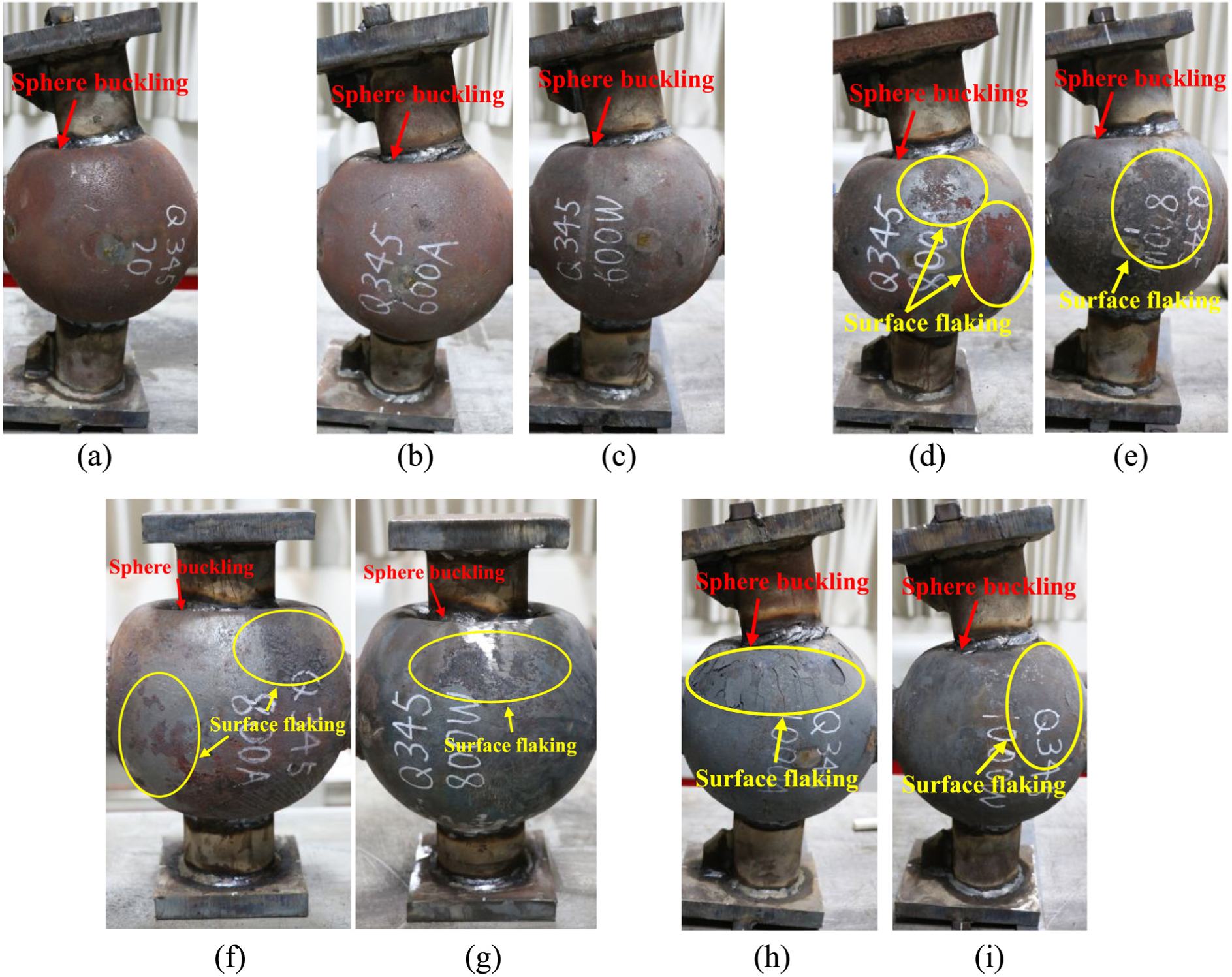
Failure modes of the test specimens: (a) J20-e20, (b) J600-e20-A, (c) J600-e20-W, (d) J800-e20-A, (e) J800-e20-W, (f) J800-e0-A, (g) J800-e0-W, (h) J1000-e20-A and (i) J1000-e20-W.
Load versus displacement relationships
The experimentally obtained load–longitudinal displacement and load–steel tube rotation relationships of the specimens after various elevated-temperature exposures are shown in Figure 5. The longitudinal displacement adopted was the average value of the measurements of the testing system itself and two LVDTs vertically laid out at the load-end; while the steel tube rotation was calculated from the lateral displacements which were measured by the horizontally arranged LVDTs. The load–longitudinal displacement and load–steel tube rotation curves differed considerably with exposure temperatures, cooling methods, and load eccentricity. Under air cooling condition, the joint specimen cooled from 600°C (J600-e20-A) presented similar load–longitudinal displacement and load–steel tube rotation responses to the specimen without heating–cooling process (J20-e20). However, for the joint specimens cooled from 800°C and 1000°C (J800-e20-A and J1000-e20-A), the maximum values and the initial slopes of their load–longitudinal displacement and load–steel tube rotation curves obviously decreased, which indicated a significant reduction in both load-bearing capacity and stiffness of the joint specimen. Nevertheless, when water cooling adopted, the load-bearing capacities of the water-cooled specimens were obviously higher than those of the air-cooled ones, though similar change trends with increasing exposure temperatures were observed. Furthermore, the influences of load eccentricity could be obtained by comparing the results of the axial compression specimens (J800-e0-A and J800-e0-W) with those of the eccentric compression specimens (J800-e20-A and J800-e20-W). It can be seen that no matter which type of cooling method was adopted, the presence of the load eccentricity significantly decreased the load-bearing capacity of welded hollow spherical joints after elevated-temperature exposure.
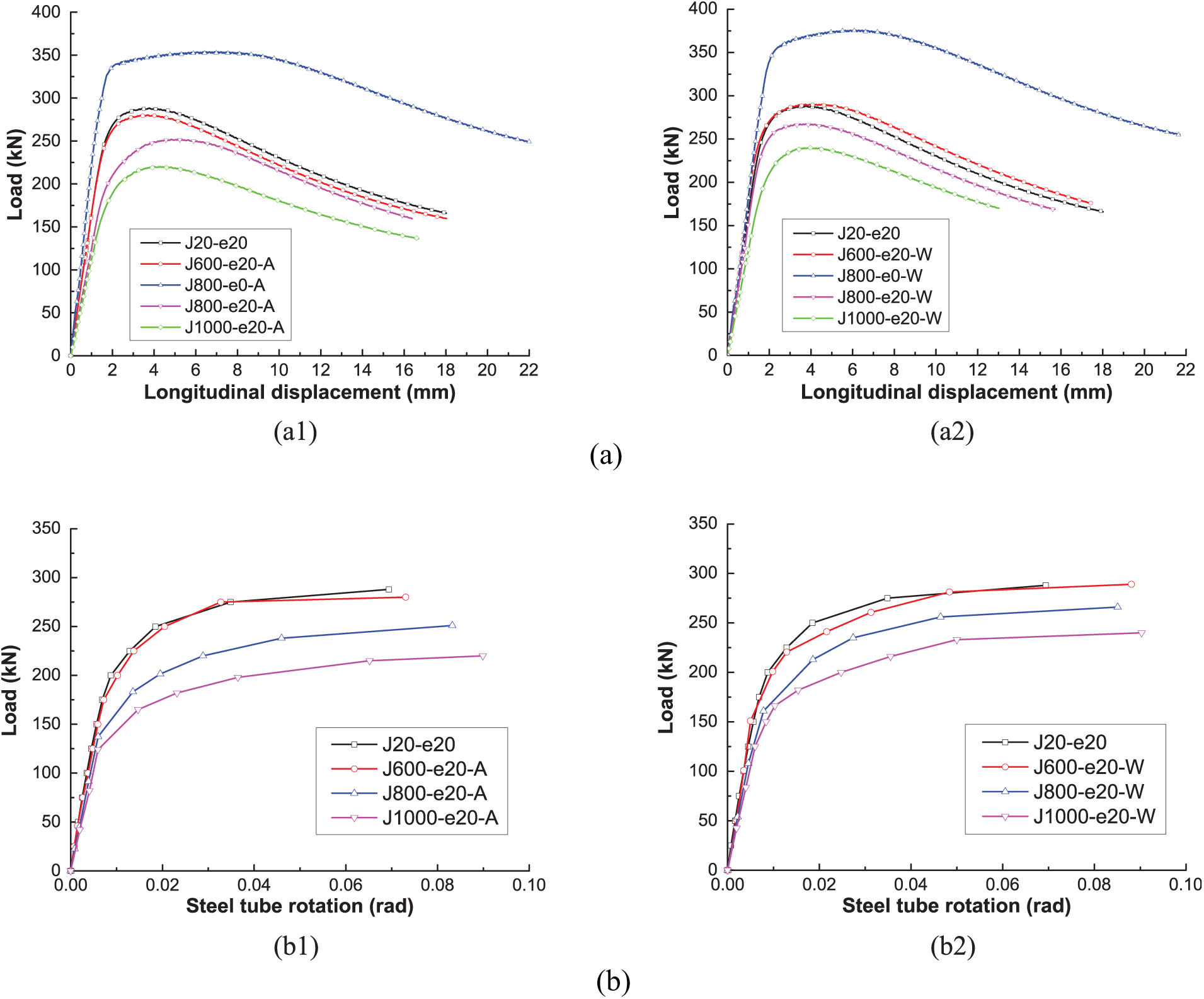
Load versus displacement relationships after various elevated-temperature exposures. (a) Load–longitudinal displacement curves: (a1) air-cooled specimens and (a2) water-cooled specimens. (b) Load–steel tube rotation curves: (b1) air-cooled specimens and (b2) water-cooled specimens.
Initial generalized stiffness
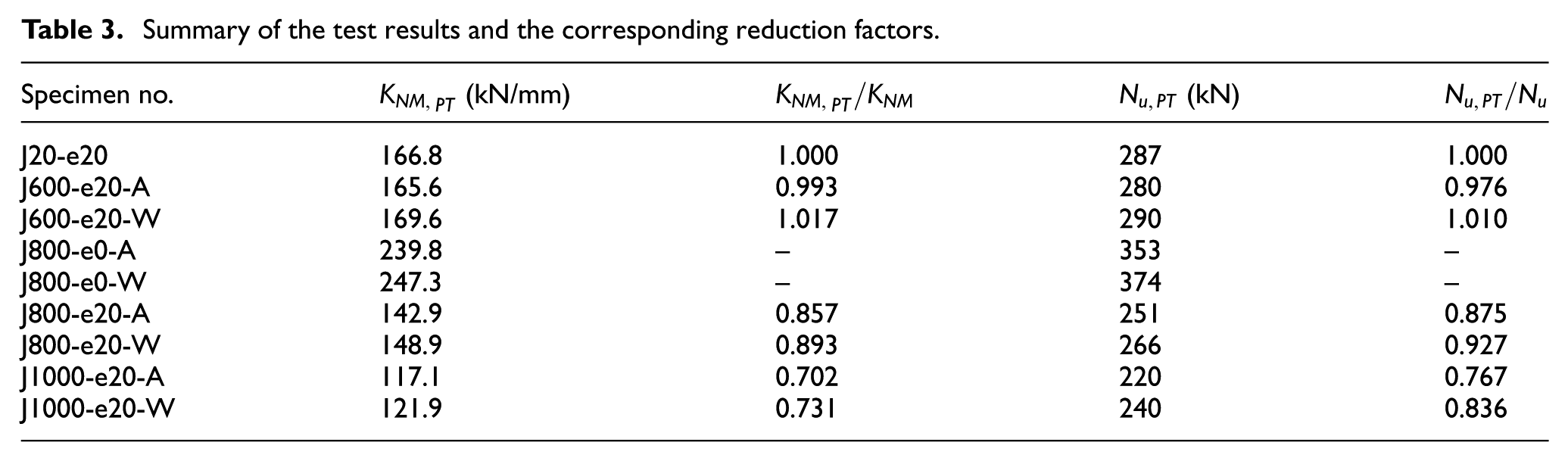
In this study, the initial generalized stiffness of the welded hollow spherical joint is defined as the initial slope of its load–longitudinal displacement curve. It is worth to mention that the initial generalized stiffness defined here is neither the commonly mentioned initial axial stiffness measured under pure axial load nor the initial flexural stiffness measured under a pure bending moment. Actually, it is a generalized stiffness that represents the integrated stiffness of the welded hollow spherical joint under the combination of axial load and bending moment. To describe the stiffness reduction of the welded hollow spherical joint caused by elevated-temperature exposure, the stiffness reduction factors are defined as the ratios of the initial generalized stiffness after elevated-temperature exposure
Summary of the test results and the corresponding reduction factors.
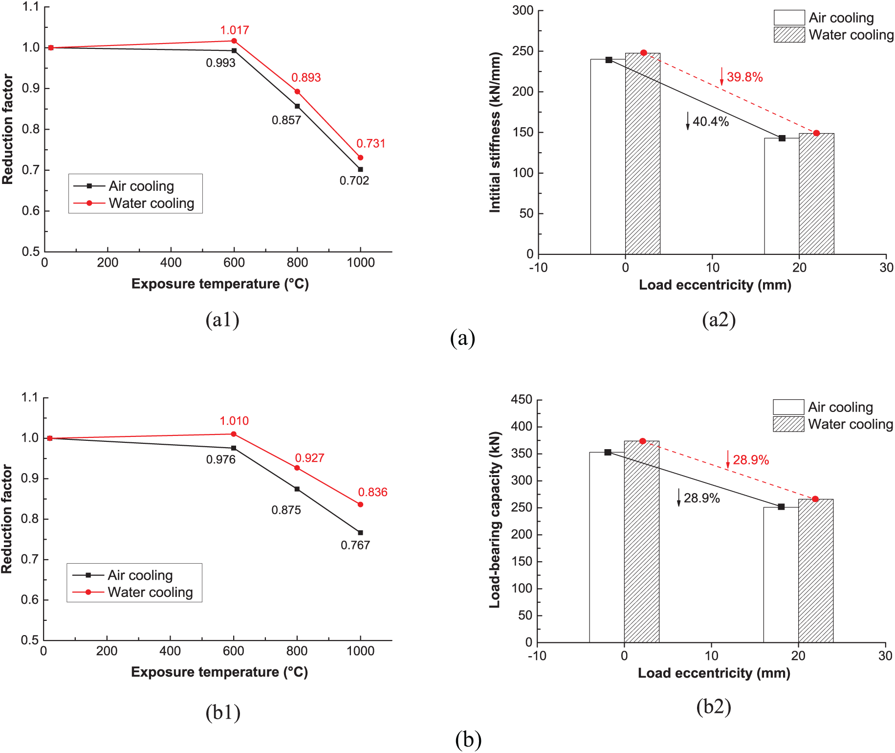
Effects of elevated-temperature exposure and load eccentricity on mechanical behavior. (a) Initial generalized stiffness: (a1) effects of elevated-temperature exposure and (a2) effects of load eccentricity. (b) Load-bearing capacity: (b1) effects of elevated-temperature exposure and (b2) effects of load eccentricity.
The initial generalized stiffness of the joint specimens kept nearly unchanged when the exposure temperature was 600°C. Subsequently, however, a significant stiffness reduction was observed with the growth of exposure temperature, which could be caused by the considerable elastic modulus reduction of structural steels after elevated-temperature exposure (Lu et al., 2016). Furthermore, the influences of different cooling methods on initial stiffness were insignificant. When the exposure temperature reached 1000°C, similar maximum reductions of 29.8% and 26.9% in initial generalized stiffness were observed for air-cooled and water-cooled specimens, respectively. In addition, the influences of load eccentricity were remarkable. After exposure to a temperature of 800°C, the initial generalized stiffness of specimens with eccentricity of 20 mm decreased by 40.4% (J800-e20-A) and 39.8% (J800-e20-W) under air and water cooling conditions, respectively, compared to the axially loaded specimens (J800-e0-A and J800-e0-W). It indicates that the presence of bending moment during the eccentric process significantly reduced the stiffness of the welded hollow spherical joint, and the reduction is unrelated with the cooling methods.
Load-bearing capacity
The load-bearing capacity reduction factors are defined as ratios of the load-bearing capacity of the joint after exposure to elevated temperatures
The load-bearing capacities of the joint specimens were nearly unaffected when the exposure temperature was 600°C. Thereafter, however, remarkable decreasing trends were presented with increasing exposure temperatures up to 1000°C, while the reductions of load-bearing capacity for air-cooled specimens were more considerable than those of specimens cooled by water. For air-cooled specimens, reductions of 12.5% and 23.3% in load-bearing capacity were observed when the exposure temperatures were 800°C and 1000°C, respectively. By contrast, for water-cooled specimens, the corresponding reductions were only 7.3% and 16.4%. This observation might be caused by the quenching effects of water cooling, which enables structural steels to exhibit higher strength than naturally air-cooled ones (Lu et al., 2016). Furthermore, the influences of load eccentricity were significant. When the exposure temperature was 800°C, the load-bearing capacity of specimens with an eccentricity of 20 mm (J800-e20-A and J800-e20-W) decreased by 28.9% compared to the specimens under axial load (J800-e0-A and J800-e0-W) because of the effects of bending moment; and the reduction of load-bearing capacity has no relationship with the cooling method.
Strain analysis
As shown in Figure 3, strain gauges and rosettes were employed to measure the strain development of the steel tubes and hollow spheres, respectively, during the loading process. For steel tube, the longitudinal strains measured by the strain gauges attached were adopted to represent its strain intensity, while for hollow sphere, based on the in-plane strains measured by the strain rosettes, the equivalent strain
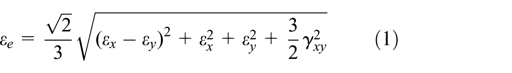
The typical load–strain intensity relationships of the joint specimens after elevated-temperature exposure are presented in Figure 7, where Lines 1–7 represent the results of different positions on the specimen. The yield strains of the structural steel after various elevated-temperature exposures were calculated according to the experimental results reported by Lu et al. (2016). The results show that during the entire loading process, the steel tubes (Positions 1 and 5) of all specimens remained elastic due to their relatively large thicknesses, which was consistent with the original intention of the experimental design. While for the hollow sphere, its strain development was closely related to the different positions, the exposure temperatures, and the cooling methods. The strain intensity obviously decreased along the longitudinal direction (i.e. from Position 2 to Position 4 and from Position 6 to Position 7), and the strain intensity on the compression side was obviously higher than the tension side. Hence, the highest strain intensity under a certain load level was observed at the intersection of the steel tube and hollow sphere on the compression side (Position 2), which was also in accordance with the failure modes shown in Figure 4.

Load–strain curves of the joint specimens after exposure to elevated temperatures: (a) J20-e20, (b) J600-e20-A, (c) J600-e20W, (d) J800-e0-A, (e) J800-e0W, (f) J800-e20-A, (g) J800-e0W, (h) J1000-e20-A, and (i) J1000-e20W.
The effects of heating–cooling on strain development were also significant. Under air cooling condition, the joint specimen presented obviously higher strain intensity and larger yielding zone with the growth of exposure temperature, which led to the earlier failure of the joint compared with the joint without elevated-temperature exposure. For specimens J20-e20 and J600-e20-A, only the intersection zone of the steel tube and the hollow sphere (Positions 2 and 6) yielded at later loading stage, whereas other regions remained elastic from beginning to end. With the increase of exposure temperature, however, the yielding zone significantly expanded. For specimens J800-e20-A and J1000-e20-A, besides Positions 2 and 6, the sphere region around Position 3 also yielded at later loading stage. By contrast, for the water-cooled joint specimens, the increase of strain intensity and the expansion of yielding zone with increasing exposure temperature were not significant. No matter how high exposure temperature the joint had been exposed to, the sphere region at Position 3 for all the water-cooled specimens remained elastic during the whole loading process, which can also be attributed to the aforementioned quenching effects of water cooling. The influences of load eccentricity on the strain development were also significant. Under certain load level and at the same position, the eccentrically loaded specimens presented obviously higher strain intensity than axially loaded specimens did.
FEA
In addition to experimental investigation, FEA was also performed via ABAQUS software package to numerically study the mechanical behavior of welded hollow spherical joint after elevated-temperature exposure. Herein, the nonlinearity of both the geometry and the material was considered.
Material properties
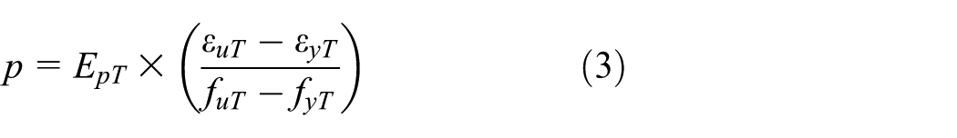
A stress–strain model proposed by Tao et al. (2013) for structural steels after elevated-temperature exposure was employed in this study and is given below
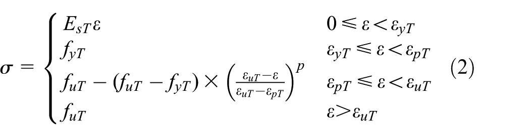
where
where
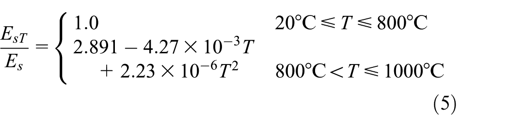
The reduction factors for elastic modulus are as follows:
For air cooling

For water cooling
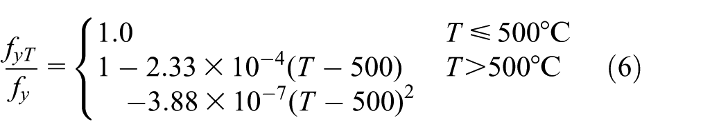
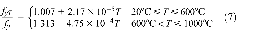
The reduction factors for yield strength are as follows:
For air cooling
For water cooling
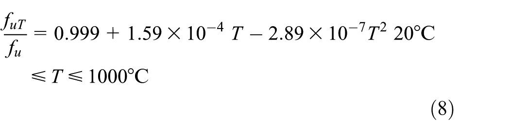
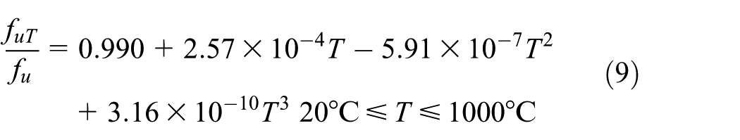
The reduction factors for ultimate strength are as follows:
For air cooling
For water cooling
The reduction factors for yield and ultimate strength under both air and water cooling conditions are also presented in Figure 9(a) and (b).
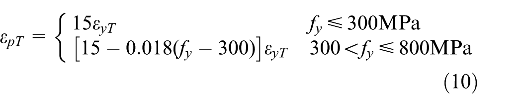
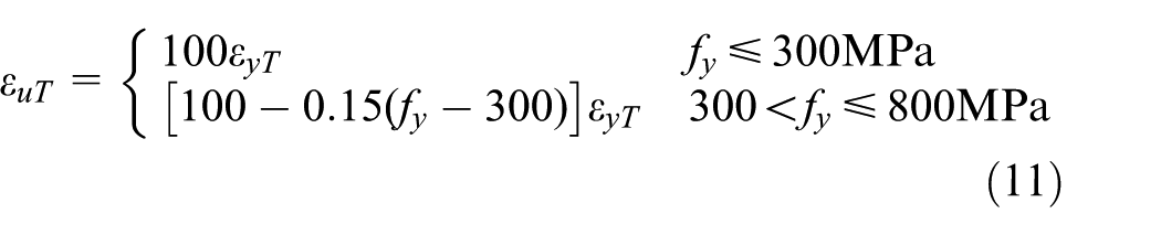
As for parameters

FE models
The 3D FE models of both the eccentrically loaded and the axially loaded welded hollow spherical joints were established with ABAQUS software. The geometries of the FE models were same to the test specimens, as shown in Figure 1. The 3D eight-node solid element with reduced integration (C3D8R) was used to mesh the model. The grids were densified in the intersection region of the steel tube and the hollow sphere, in which the stress level is high, to improve analysis accuracy. According to sensitivity analysis of the grid size, the grid sizes with 27044 elements and 16272 elements were used to mesh the eccentrically loaded and axially loaded FE models, respectively.
The eigenvalue buckling analysis was conducted first and the lowest buckling mode scaled by an amplification factor of 1000/L was introduced into the FE model as the initial geometrical imperfection, where L refers to the length of the joint specimen. After that, the elastoplastic analysis considering the nonlinearity of both the geometry and the materials was performed. Given that the thermal conductivity of the steel material is excellent and the heating-cooling process described in section “Test conditions and procedures” was adopted, the temperature distribution of the entire joint can be considered uniform. Hence, the same material model can be employed for the whole FE model after exposure to a certain temperature. For both axially loaded and eccentrically loaded models, the pinned end conditions, which are same to those of the test specimens, were adopted.
Validations of the FE models
The FEA results were compared with the experimental results obtained in this study to verify the validity of the proposed FE models. As shown in Figure 8, comparisons were conducted on the typical failure modes and the load–longitudinal displacement relationships. And a good agreement can be observed between the results of FEA and experiment.
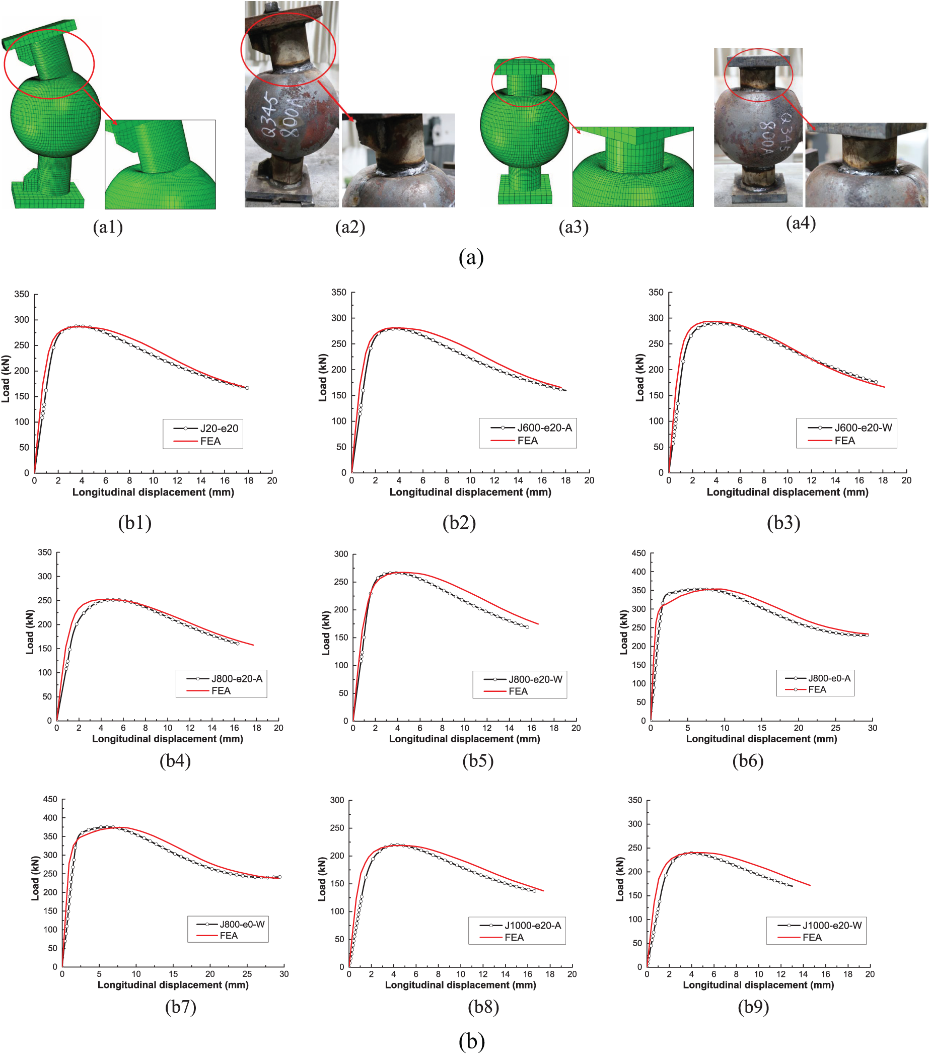
Comparisons of the FEA results with the experimental results. (a) Comparisons of the typical failure modes. (a1) FEA of J800-e20-A, (a2) experimental results of J800-e20-A, (a3) FEA of J800-e0-A, and (a4) experimental results of J800-e0-A. (b) Comparisons of the load–longitudinal displacement relationships: (b1) J20-e20, (b2) J600-e20-A, (b3) J600-e20-W, (b4) J800-e20-A, (b5) J800-e20-W, (b6) J800-e0-A, (b7) J800-e0-W, (b8) J1000-e20-A, and (b9) J1000-e20-W.
Parametric studies and calculation formula
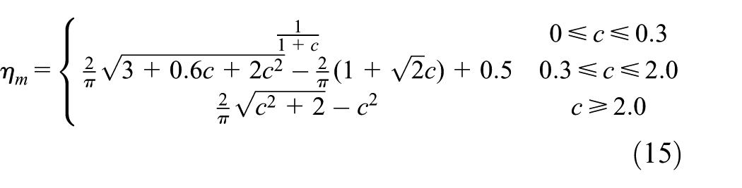
In design code JGJ7-2010, a practical formula is recommended to calculate the load-bearing capacity of welded hollow spherical joints subjected to eccentric load at ambient temperature without fire exposure, which is given below

where
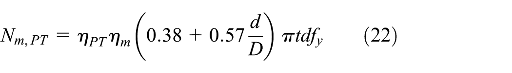
To maintain consistent form with equation (15) which has been widely used by engineers, a reduction factor

where
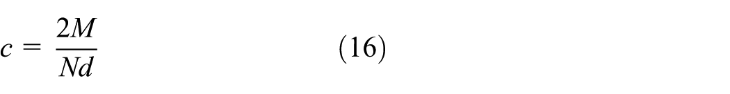
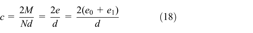
where M and N are the moment and axial force applied on the hollow sphere via the steel tube, and d is the external diameter of the steel tube. Under eccentric load condition in this study, the relationship between M and N can be expressed as follows

where e denotes the total load eccentricity and
For FEA,
As for the load-bearing capacity of the axially loaded welded hollow spherical joints
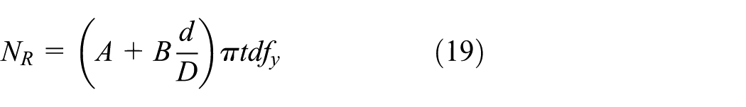
where A and B are the undetermined coefficients. Hence, three parameters, namely,
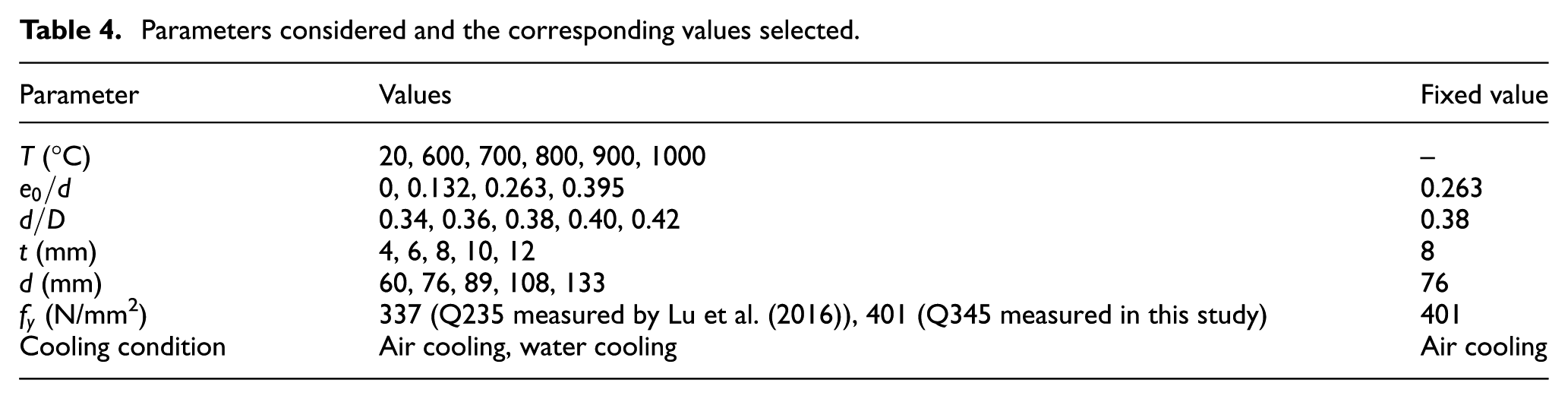
To determine the form of
Parameters considered and the corresponding values selected.
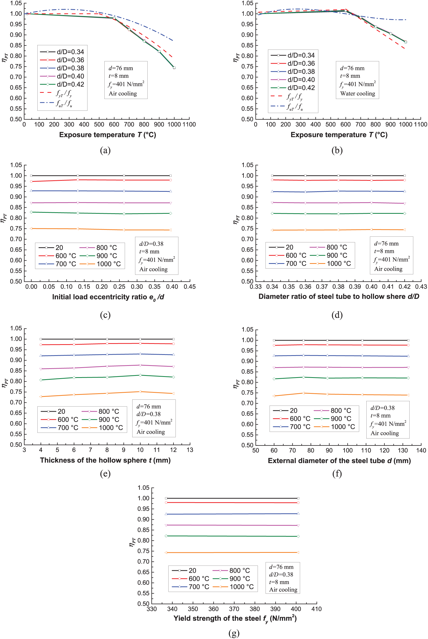
Influences of the key parameters on
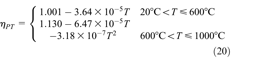
The results of the parametric analysis show that
Under air cooling condition
Under water cooling condition (for conservative consideration, the insignificant increase of
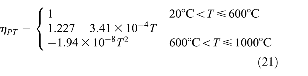
It is worth to be mentioned that
With respect to the undetermined coefficients A and B, by taking
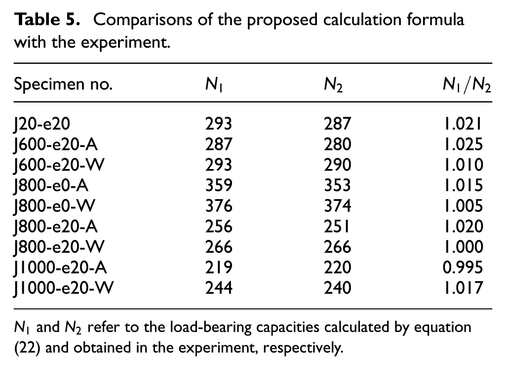
The load-bearing capacities predicted by equation (22) are compared with those of FEA and experiment, as shown in Figure 10 and Table 5, respectively. As shown, a good agreement is observed, which confirmed the validity of the calculation formula.
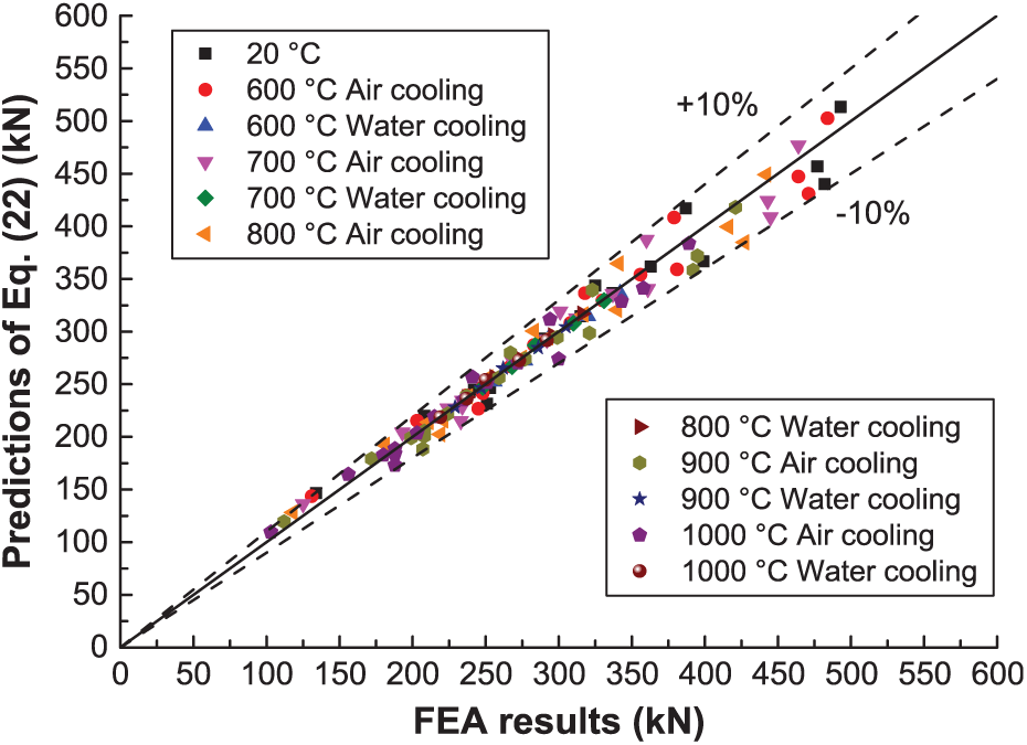
Comparisons of the proposed calculation formula with the FEA.
Comparisons of the proposed calculation formula with the experiment.
Conclusion
In this article, the details of both experimental and numerical investigations into the behavior of the eccentrically loaded welded hollow spherical joints after elevated-temperature exposure were presented. And following conclusions can be drawn:
The welded hollow spherical joints subjected to both axial and eccentric compressions presented similar elastoplastic buckling collapse failure mode, regardless of the exposure temperatures and cooling methods. Furthermore, both axially and eccentrically loaded specimens exhibited significant ductile behavior after reaching the peak loads.
The initial generalized stiffness and load-bearing capacity of the joints significantly decreased when the exposure temperatures exceeded 600°C. Furthermore, different cooling methods have insignificant influences on the stiffness. However, water-cooled joints generally presented higher load-bearing capacity than air-cooled joints. Moreover, the load eccentricity also remarkably reduced the load-bearing capacity of the joints.
The strain development was closely related to the positions on the hollow sphere, the exposure temperatures, and the cooling methods. The highest strain intensity was observed at the intersection of the steel tube and the hollow sphere on the compression side. For air cooling, the joints presented obviously higher strain intensity and larger yielding zone with increasing exposure temperature. While for water cooling, the increase of strain intensity and the expansion of yielding zone with increasing exposure temperature were not significant. In addition, the eccentrically loaded specimens presented obviously higher strain intensity than the axially loaded specimens.
Based on the establishment of the FE models and subsequent parametric analysis, a calculation formula was proposed to evaluate the load-bearing capacity of eccentrically loaded welded hollow spherical joints after elevated-temperature exposure. The application of the formula can be helpful to in the post-fire safety assessment of space latticed structures of which welded hollow spherical joints were involved.
Footnotes
Declaration of Conflicting Interests
The author(s) declared no potential conflicts of interest with respect to the research, authorship, and/or publication of this article.
Funding
The author(s) disclosed receipt of the following financial support for the research, authorship, and/or publication of this article: This study was financially supported by the National Natural Science Foundation of China (Grant No. 51678404). This study was also financially supported by the Chinese Scholarship Council (File No. 201706250068), which enabled the authors to collaborate with Prof. Huiming Yin at Columbia University.