
Abstract
Skew bridges induce inherently coupled bending and torsion response. The actual relevance of this coupling for the dynamic response under moving loads such as those arising in high-speed railways is not well known, introducing uncertainties unless costly three-dimensional dynamic models are used. In this work, models are developed based on beam theory and analytical extraction of vibration modes, which are both simple and fast. First, a general three-dimensional beam model is derived, involving both bending and torsional modes. In the following, a simplified beam model is proposed involving only bending modes. In both cases, the eigenfrequencies, eigenmodes and orthogonality relationships are determined analytically from the boundary conditions, and the dynamic response is obtained numerically in the time domain. Both models are validated through representative realistic examples by comparing with two types of finite element models: a stick model with three-dimensional beams and a full three-dimensional model with shell elements. Finally, parametric studies are performed with the simplified beam model for identifying parameters that influence the dynamic response under traffic loads. The results show that the degree of skewness has an important influence on the vertical displacement, but hardly on the vertical acceleration of the bridge. The torsional stiffness has a significant effect on the vertical displacement when the skew angle is large. Finally, the span length reduces the skewness effect on the dynamic behaviour of the bridge.
Introduction
The dynamic response of railway bridges subjected to traffic loads of high-speed trains (above 200 km/h) is a significant design issue, which has been included in the recent eurocode requirements (CEN, 2003). Background studies for this purpose have often been limited to simple bridges with line beam bending behaviour (ERRI, 1999; Fryba, 1996). Moreover, the High Speed Load Model (HSLM) used for design in CEN (2003) is also based on this assumption. However, a substantial number of bridges in the new high-speed lines (HSLs) have skew supports, developing coupled bending and torsion even for centred loads in single-track bridges. As an example, in recent surveys we have identified 50 skewed underpasses out of 108 slab portal frames in the Madrid–Zaragoza HSL (Soriano Muñoz, 2016) and 9 skewed simply supported bridges out of 27 in the same line (Barrios Fragoso, 2017).
The structural effect of skewness is an additional torsion on the bridge deck (Kollbrunner and Basler, 1969; Manterola, 2006) which modifies the structural response. Several studies following analytical, numerical as well as experimental approaches have been made during the last decades in order to better understand the behaviour of skew bridges under static and dynamic loadings. Of special relevance is the research related to highway skew bridges subjected to earthquake loading: early work on this subject was reported by Ghobarah and Tso (1974), in which a closed-form solution based on a beam model capable of capturing both flexural and torsional modes was proposed for skew bridges with intermediate supports. Maragakis and Jennings (1987) obtained the earthquake response of the skew bridge, modelling the bridge deck as a rigid body. The application of finite element (FE) stick models using beam elements was introduced by Wakefield et al. (1991), and later further developed by Abdel-Mohti and Pekcan (2008), Kaviani et al. (2012), Meng et al. (2001), Meng and Lui (2000), Nielson and DesRoches (2007), Serdar and Folić (2018) and Yang et al. (2015). Despite their simplicity, stick models can provide reasonably good approximations for preliminary assessments. More detailed FE three-dimensional (3D) models using shell and beam elements have been also applied for this problem (Abdel-Mohti and Pekcan, 2008; Deng et al., 2015; Mallick and Raychowdhury, 2015; Meng and Lui, 2000, 2002; Nouri and Ahmadi, 2012; Zakeri et al., 2014).
Regarding the dynamic response of skew bridges under moving traffic loads, most of the work has been performed on FE models using a combination of shell and beam elements and assisted by experimental testing (Ashebo et al., 2007; Bishara et al., 1993; He et al., 2012; Helba and Kennedy, 1995; Khaloo and Mirzabozorg, 2003; Menassa et al., 2007; Xue et al., 2018). FE models may provide good approximations, but require the end user significant effort for defining the model (element types and sizes, geometry, material properties, supports, connections, etc.). In addition, they are costly in terms of engineering and computational time. Therefore, their use is limited to specific case studies and may not be practical for parametric studies such as Monte Carlo simulations or other situations requiring a large number of case studies.
A possible alternative is to develop models following analytical solutions based on beam theory, which capture the behaviour of the skew bridge and yield sufficient accuracy. The advantage of such analytical models is that the data input is much simpler (only general structural parameters such as mass, span length and flexural and torsional stiffness) facilitating their use for the end user and, of course, enabling massive parametric studies. However, this approach implies limitations which must also be understood. It requires line beam-type bridges in which the deck cross-section behaves rigidly enough and may be represented by beam models with bending and torsion. Open cross-sections which may experience significant distortion would generally need more detailed 3D FE models.
In this work, we have developed numerical models based on beam theory and closed-form modal analysis for the response of skew bridges subjected to moving traffic loads. First, a general model is described which involves bending and torsion modes of the beam. In the following, a simpler model is presented which accepts some approximations and involves only vertical bending of the beam. The dynamic response is obtained in the time domain using a piecewise exact algorithm. Both models are validated on representative examples and compared against the results obtained by 3D FE models. Finally, several parametric studies are performed with the simplified model in order to identify variables that influence significantly the vertical dynamic response of skew bridges under traffic loads.
The general beam model
Although the theory may be applied to more general settings, for the sake of simplicity, a simply supported skew bridge as shown in Figure 1 will be considered within this work. The skewness angle
The bridge deck is modelled as a linear elastic 3D Euler–Bernoulli beam supported at the ends;
The bridge deck is very stiff in the horizontal xy plane, so transverse deflections in the y direction will be neglected;
The bending stiffness EI, torsional stiffness GJ and mass per unit length
Warping and distortion effects for the cross-section of the bridge deck may be neglected. It is noted that with this assumption the application is limited to closed-type cross-sections, such as hollow slabs or prismatic box-girder bridges for which the warping and distortion are small (Kollbrunner and Basler, 1969; Menn, 1990; Mo et al., 2000; Nallasivam et al., 2007; Waldron, 1988).
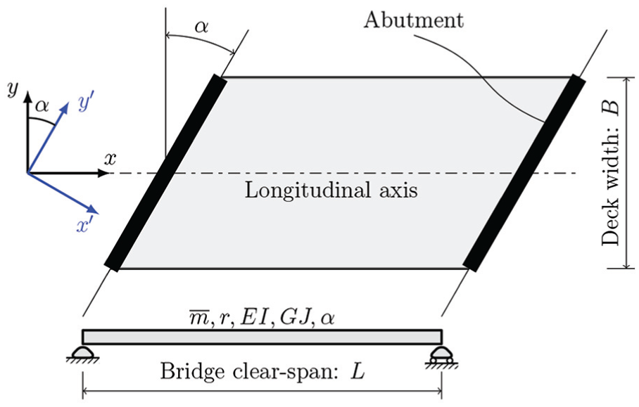
A simply supported skew bridge: in plane view and bridge model’s sketch.
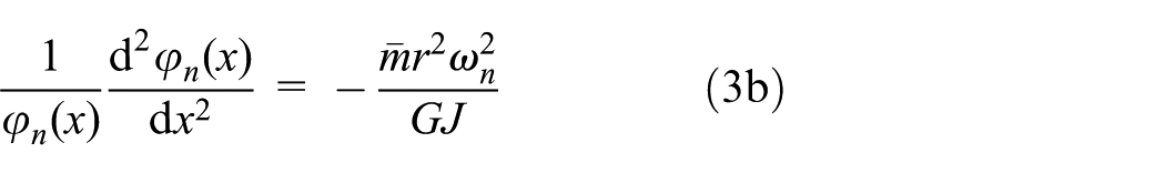
Under these assumptions, the bending of the bridge in the xz plane and its twisting about the x-axis are the only deformations of the bridge deck. The governing equations of motion for transverse and torsional vibrations are
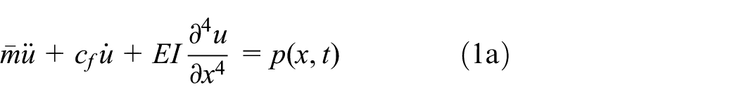
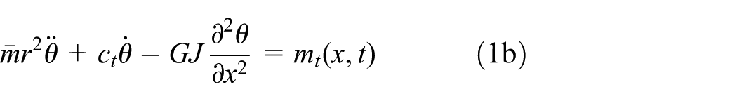
where r is the radius of gyration;
Natural frequencies and mode shapes
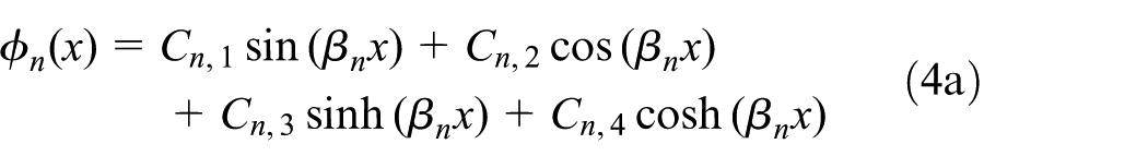
Using modal analysis, the solution for free vibrations of the bridge can be expressed decoupled with an infinite sum of modal coordinates and mode shapes as

where
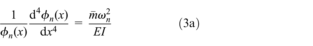
The eigenvalue solution to the above equations may be expressed using standard theory (e.g. Clough and Penzien, 1993)

where
The boundary conditions are shown in Figure 1, with the bridge simply supported at the abutment ends. At the support lines, there are zero vertical displacements

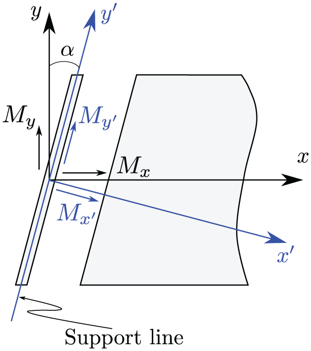
Coordinate systems.
Hence, the boundary conditions for the problem can be written as


Developing these six conditions, a homogeneous system of equations is obtained as

where
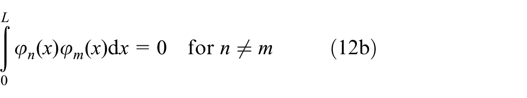
Orthogonality conditions
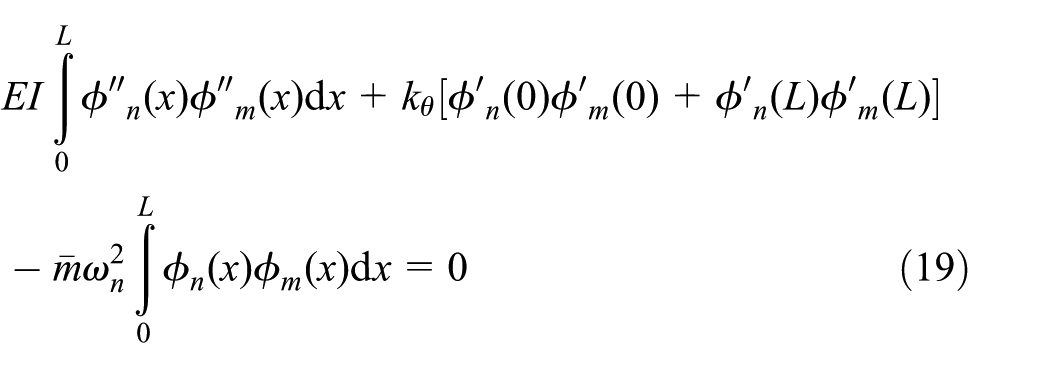
In order to apply the modal superposition, it is necessary to ensure the orthogonality relationship between the mode shapes. Starting from equations (3), these can be reformulated by multiplying both sides of these by an arbitrary mode
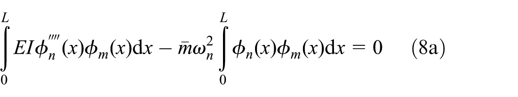
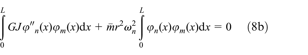
Integrating by parts these equations (twice for equation (8a) and once for equation (8b)) and applying the boundary conditions derived for the problem gives
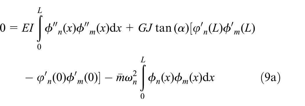
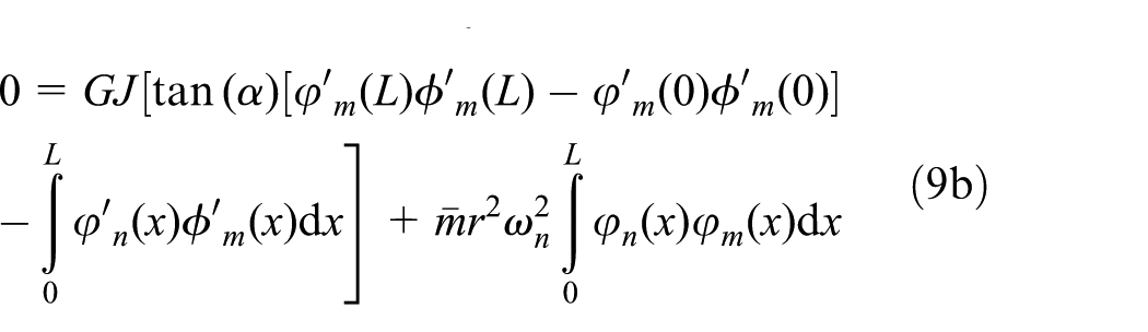
Interchanging indices n and m in equation (9) and subtracting from its original form yields the following relations for any
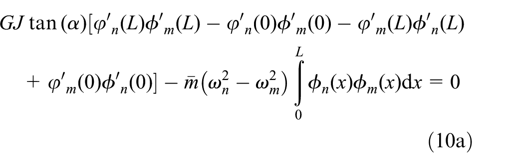
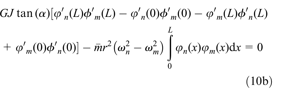
Next, subtracting equation (10a) from equation (10b) gives
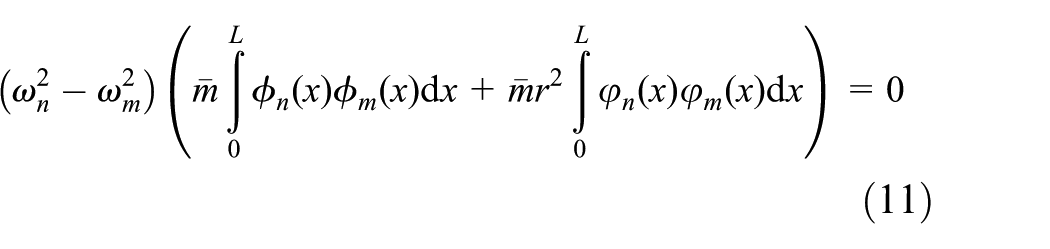
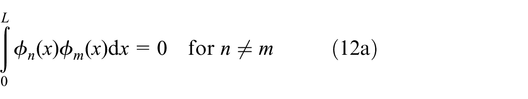
Finally, considering
Response to moving loads
We now apply modal superposition for obtaining the response of the skew bridge due to moving loads. Starting with a single moving load P (Figure 3(a)), the distributed vertical force and twisting moment for equations (1a) and (1b) may be expressed as

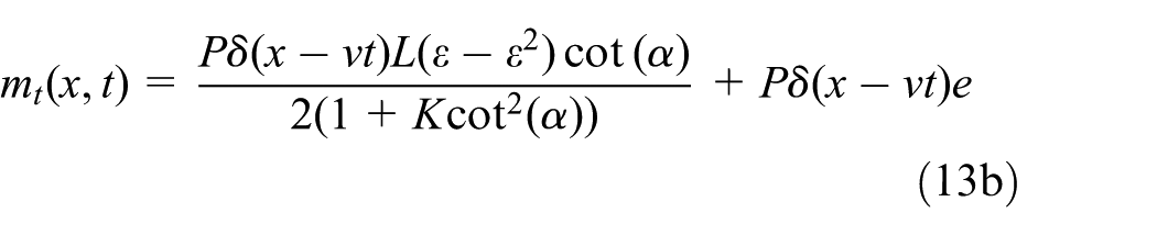
where
with
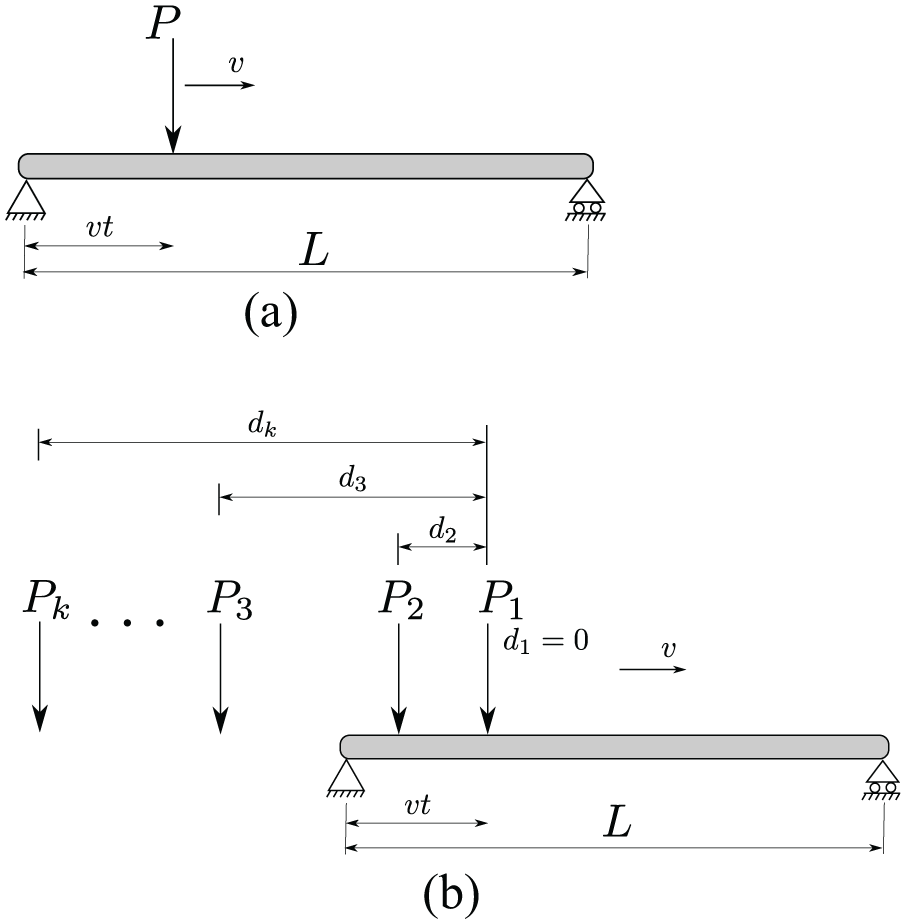
Moving loads: (a) a moving load and (b) a convoy of moving loads.
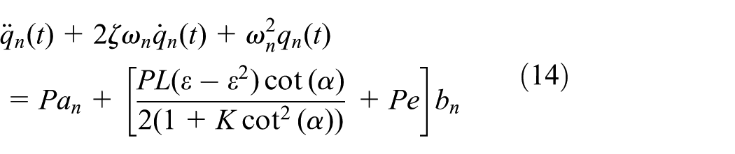
The uncoupled differential equation (14) may then be solved in time using the piecewise exact method (Clough and Penzien, 1993).
For the case of a convoy of moving loads (Figure 3b), the uncoupled differential equations in the generalised coordinates for each mode of vibration n are
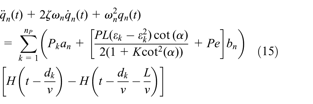
where
The simplified beam model
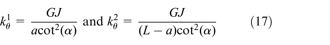
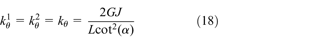
In this section, a simplified beam model which includes only bending in the vertical xz plane is developed. This model includes an approximation to the bending restraint provided by the skew supports which simplifies the calculations. The torsional moments induced at the supports introduce a negative (hogging) bending moment as shown in Figure 4(a) (Kollbrunner and Basler, 1969; Manterola, 2006). As a result, for the purpose of vertical flexure the simply supported skew beam behaves like an elastically fixed beam, with rotational supports of stiffness constants
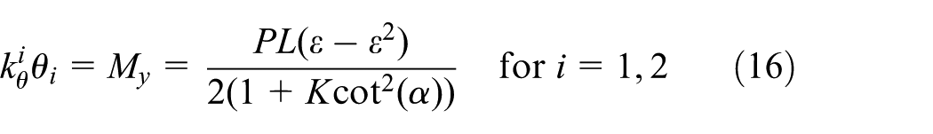
with
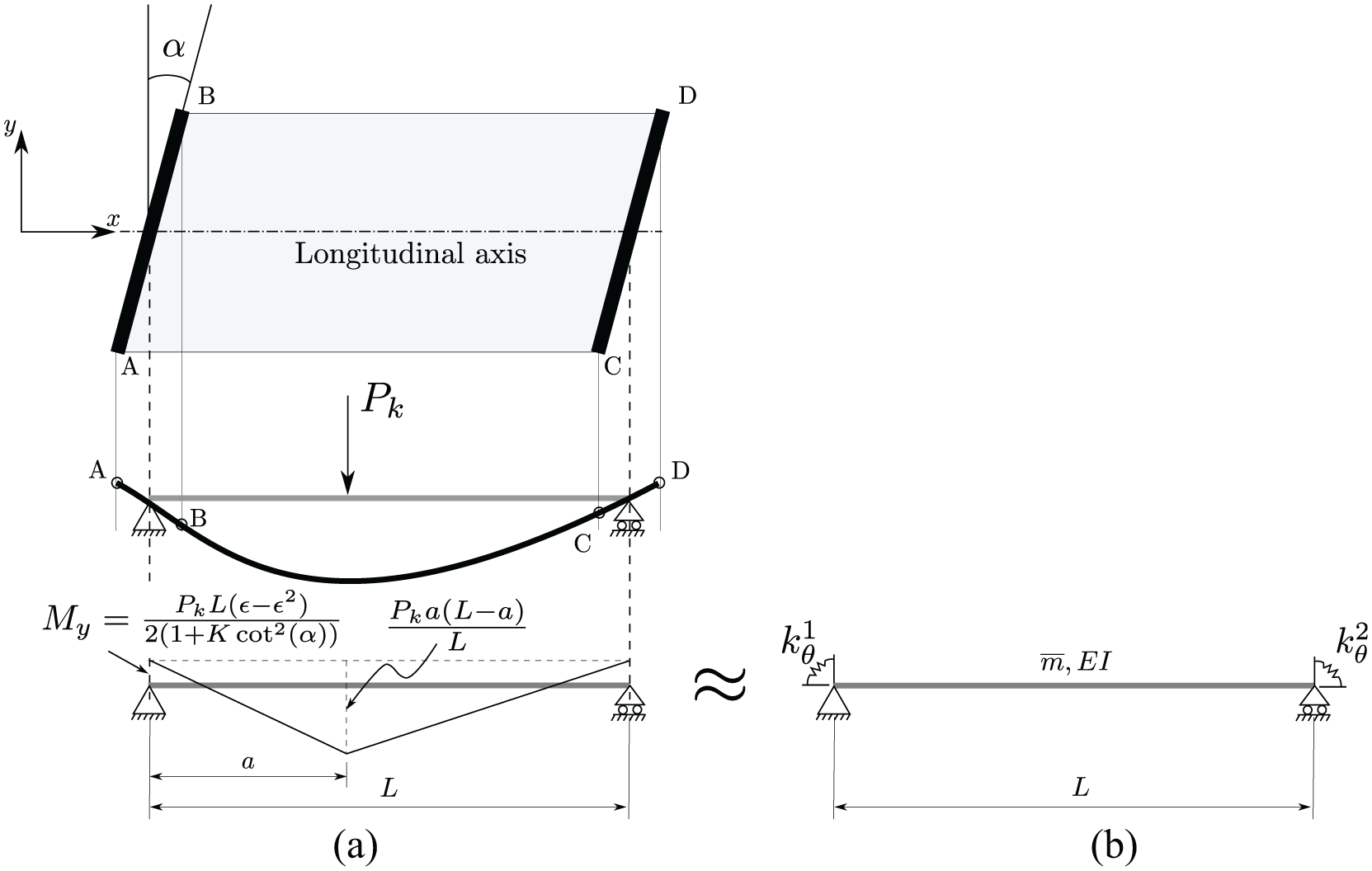
(a) Diagram of bending moment of a skew bridge under a static load and (b) a simplified model considering only beam bending in the vertical xz plane.
This yields different support stiffnesses at both ends, and moreover non-constant as a function of the position a of the load. An approximation is proposed to consider the same stiffness in both supports, by which a constant stiffness of the rotational support is taken for
As a result, considering the above value for the elastic rotational support, this simplified beam model includes only bending in the vertical plane, thus allowing simpler two-dimensional (2D) beam models to be employed.
Natural frequencies and mode shapes
The governing equation for the free vibration of the simplified model is similar to equation (3a). The solution of this equation is given in equation (4a). Details for the determination of frequencies and the associated mode shapes may be found in Karnovsky and Lebed (2000).
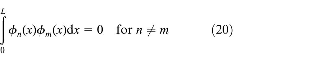
Orthogonality conditions
Similar to the analysis in the previous section, equation (3a) may be rewritten, using the boundary conditions of the simplified model, as
Interchanging the indices n and m in equation (19) and subtracting the resulting equation from its original form, considering
Response to moving loads
The dynamic response of the bridge under moving loads is obtained similarly to the model in the previous section ‘The general beam model’, the only difference being that the torsional response is not considered.
Numerical validations
The above models will be applied to a typical box-slab single-track bridge, designed for high-speed railway, with cross-section as shown in Figure 5. This is a closed-type cross-section, which fulfils the assumption made for the beam model of neglecting warping and distortion effects. The geometric and mechanical properties are as follows:
Span
Elastic modulus
Damping ratio
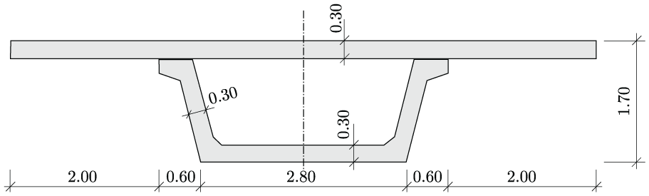
Cross-section of the simply supported bridge.
The results obtained by the two proposed beam models will be compared between themselves and with the FE models of two types: (1) a model with 3D Euler–Bernoulli beam elements (stick model; see Figure 6(a)), using the program FEAP (Taylor, 2014), and (2) a model with shell elements, using the program Abaqus (Simulia, 2017; see Figure 6(b)).
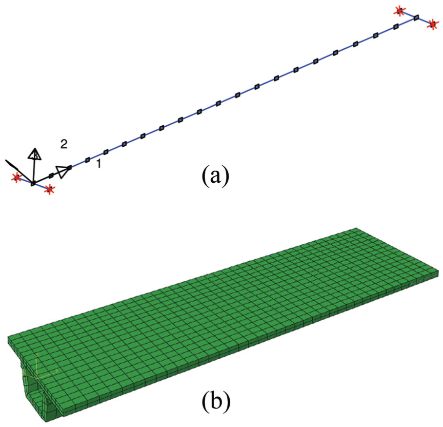
FE models: (a) FE stick model and (b) FE shell model.
The bridge is subjected to the action of high-speed railway traffic, performing dynamic analyses for moving loads representing each axle of the train. Such moving load models are the basic design methods when dynamic analysis is required (CEN, 2003). They are also appropriate for the present case in which the bridge mass amounts to
The dynamic response in the FE models is obtained using modal analysis in the time domain with a time step
Frequencies of the first five modes of vibration of different models (in Hz).
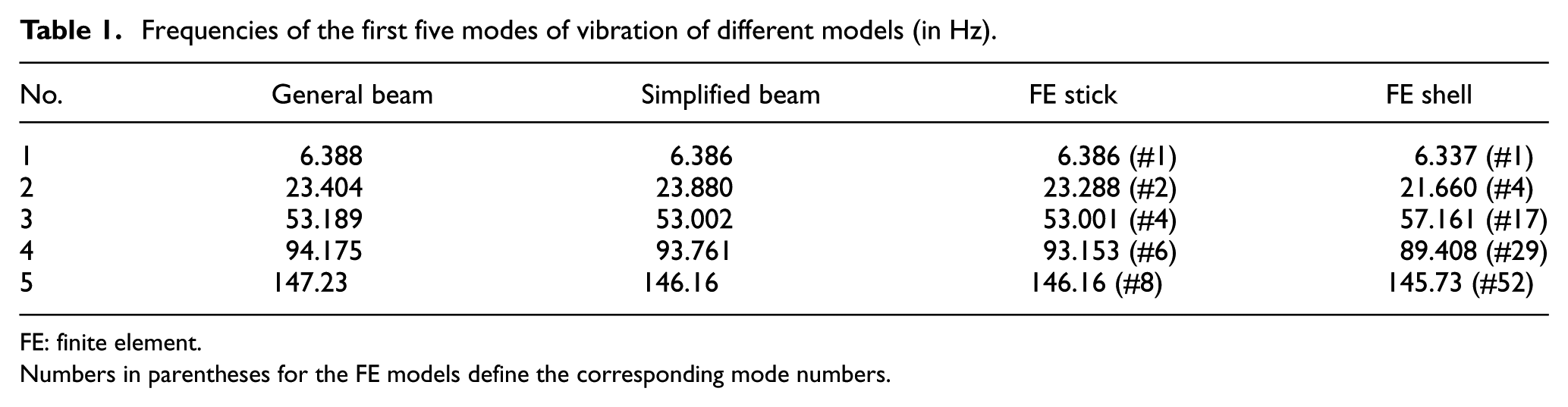
FE: finite element.
Numbers in parentheses for the FE models define the corresponding mode numbers.
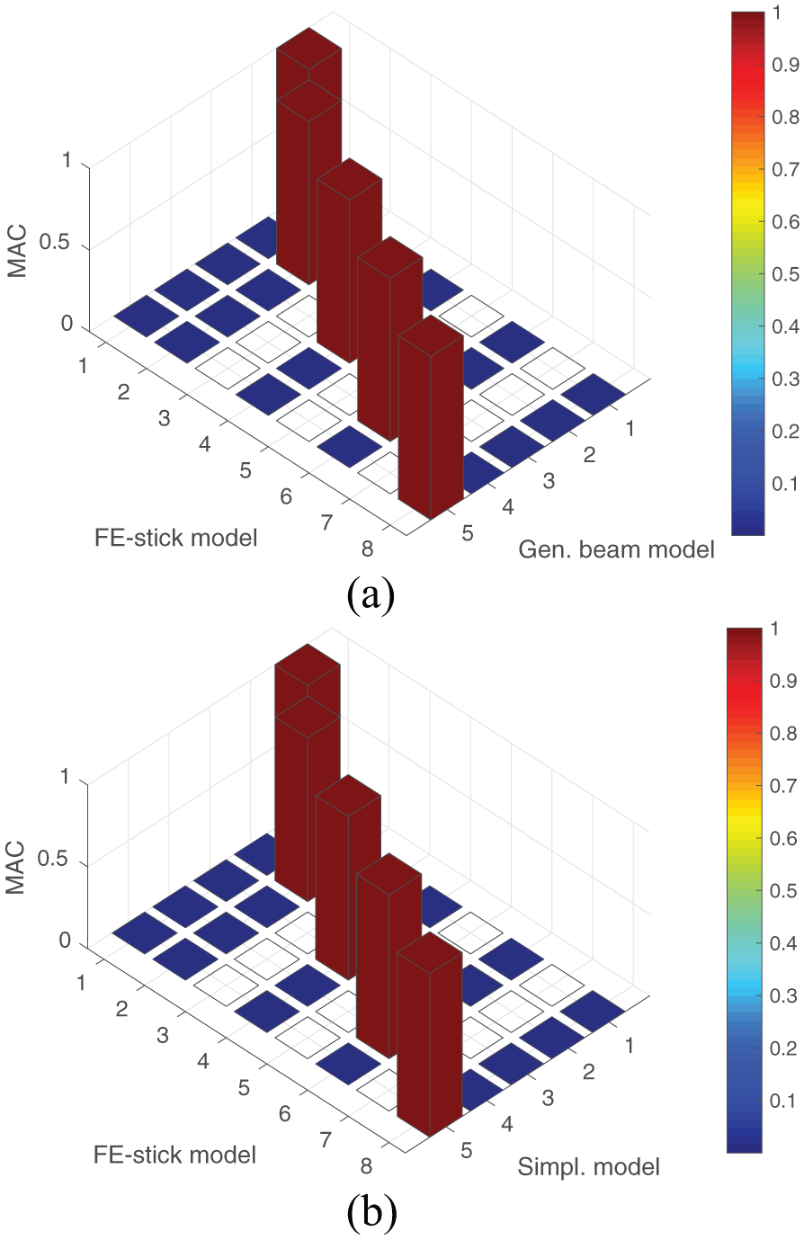
Comparison of modal assurance criterion (MAC) between the modes of the beam models and the FE stick model: (a) MAC between the general beam model and the FE stick model and (b) MAC between the simplified beam model and the FE stick model.
The loading corresponds to 1 of the 10 virtual trains defining the HSLM, in particular HSLM-A1 (CEN, 2003). This train consists of 18 intermediate coaches and power cars at both ends, with a total of 50 axles with the loads of 170 kN/axle. The dynamic analyses are carried out for train speeds ranging from 100 to 300 km/h in increments of 2 km/h.
The dynamic response for displacement and acceleration at the train speed of 206 km/h is presented in Figure 8, showing a very close approximation between the two beam models and the two FE models.
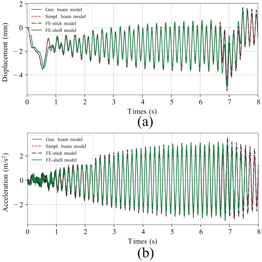
Dynamic response for the HSLM-A1 train for
Furthermore, for this case a large amplification of the response is obtained, typical of resonance. In effect, for a simply supported bridge, the critical train velocities which may produce resonance can be estimated by the simple relation (CEN, 2003)
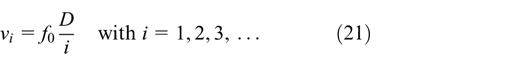
where
The envelope curves of maximum response for the velocity range (100–300 km/h) are presented in Figure 9.
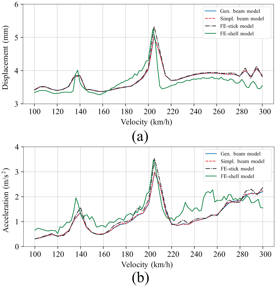
Envelopes of the maximum response for the HSLM-A1 train between the speeds of 100 and 300 km/h: (a) envelope of maximum deflection at L/2 and (b) envelope of maximum acceleration at L/2.
These show two response peaks (both for deflection and acceleration), for 206 and 138 km/h, close to the predicted critical velocities. Therefore, it can be remarked that the estimation of the train velocities of resonance proposed by CEN (2003) is still valid for skew bridges. Furthermore, from Figures 8 and 9, it can be concluded that the results obtained using the general beam model and the simplified beam model agree well between themselves and with the results from the FE models (stick and shell). It must be remarked that, for the FE shell model at non-resonant speeds, larger differences are obtained with respect to all the other beam models (analytical or FE). These are of minor relevance in the deflection envelope but more significant in the acceleration envelope. This is interpreted as the contribution of vibrations of extra modes which appear only in the 3D shell model due to additional degrees of freedom which do not exist in the beam models, but which do not affect significantly the global vertical deflection.
Finally, the CPU time required for completing each analysis using the beam model was
Parametric studies
Having validated the analytical beam models in the previous section, in the following three parametric studies are performed using the simplified beam model, in order to identify variables which influence significantly the dynamic response. The same structural properties as the skew bridge from the previous section are adopted. In each study, the value of one parameter will be changed, and the dynamic response for the HSLM-A1 train will be shown as a function of the studied parameter. The results presented will be the natural frequencies for the first two modes of vibration, as well as the maximum displacements and accelerations at mid-span.
Effect of skew angle
The skew angle
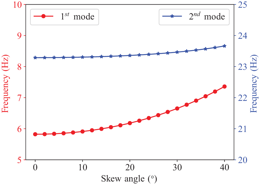
Effect of skewness on the natural frequencies.
Figure 11(a) and (b) shows how the dynamic response varies with the skew angle. An important change is also observed for the deflection: in general it decreases with the increasing skew angle. A sharp change in slope is observed approximately at the skew angle of 15 (Figure 11(a)). It is noted that this sharp change at the same skew angle is also observed in the value of the frequency of the first mode (Figure 10). From this value of the skew angle, the maximum deflection decreases faster. Furthermore, an increase in the resonant train velocity is also observed when the skew angle increases, due to the growing natural frequency of the first mode. Regarding the maximum acceleration, the skew angle does not have a significant influence: the acceleration hardly increases when the skew angle grows.
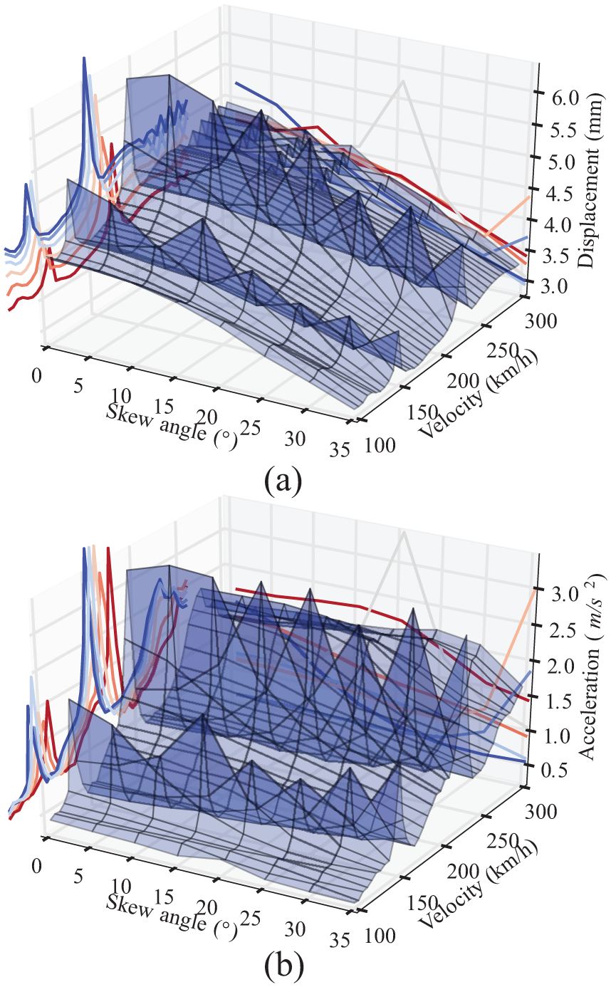
Effect of skewness on the dynamic response: (a) maximum deflection and (b) maximum acceleration.
Effect of the torsional-to-flexural stiffness ratio
For this study, the ratio between the torsional stiffness and the flexural stiffness
Figure 12 shows the variation of the frequency of the first two modes of vibration, from which it can be observed that the torsional-to-flexural stiffness ratio has an important influence on the eigenfrequencies when the skew angle is large (i.e. 30).
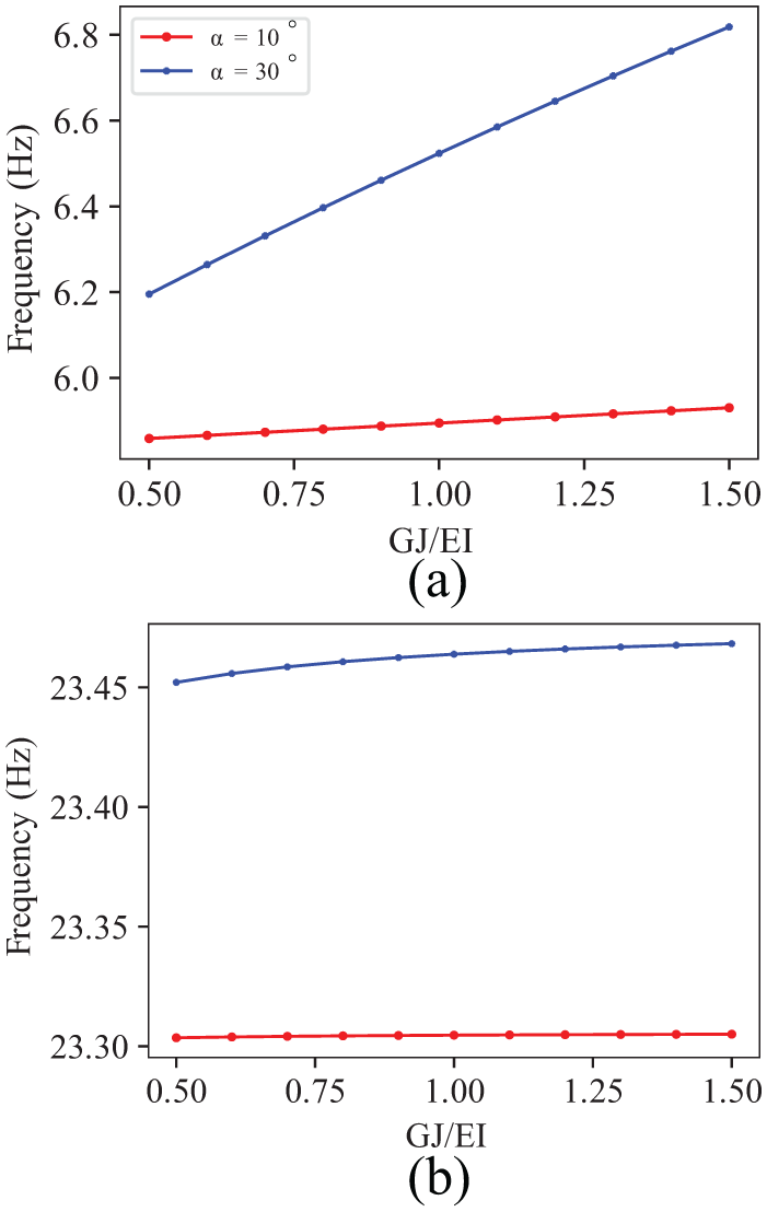
Effect of the torsional-to-flexural stiffness ratio on the eigenfrequencies: (a) first mode and (b) second mode.
From Figure 13(a), for the case of
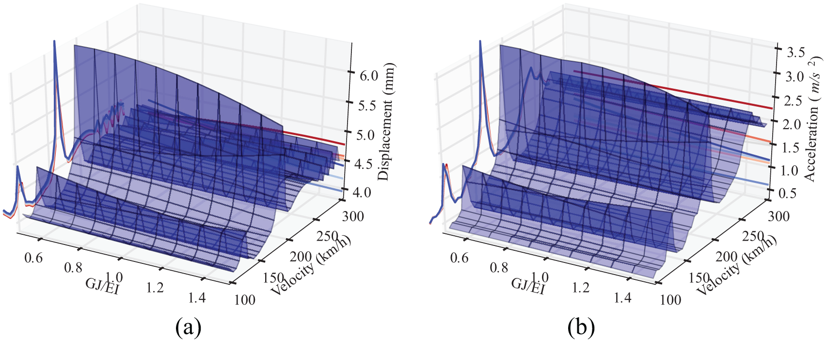
Effect of the torsional-to-flexural stiffness ratio on the maximum dynamic response for a skew angle of
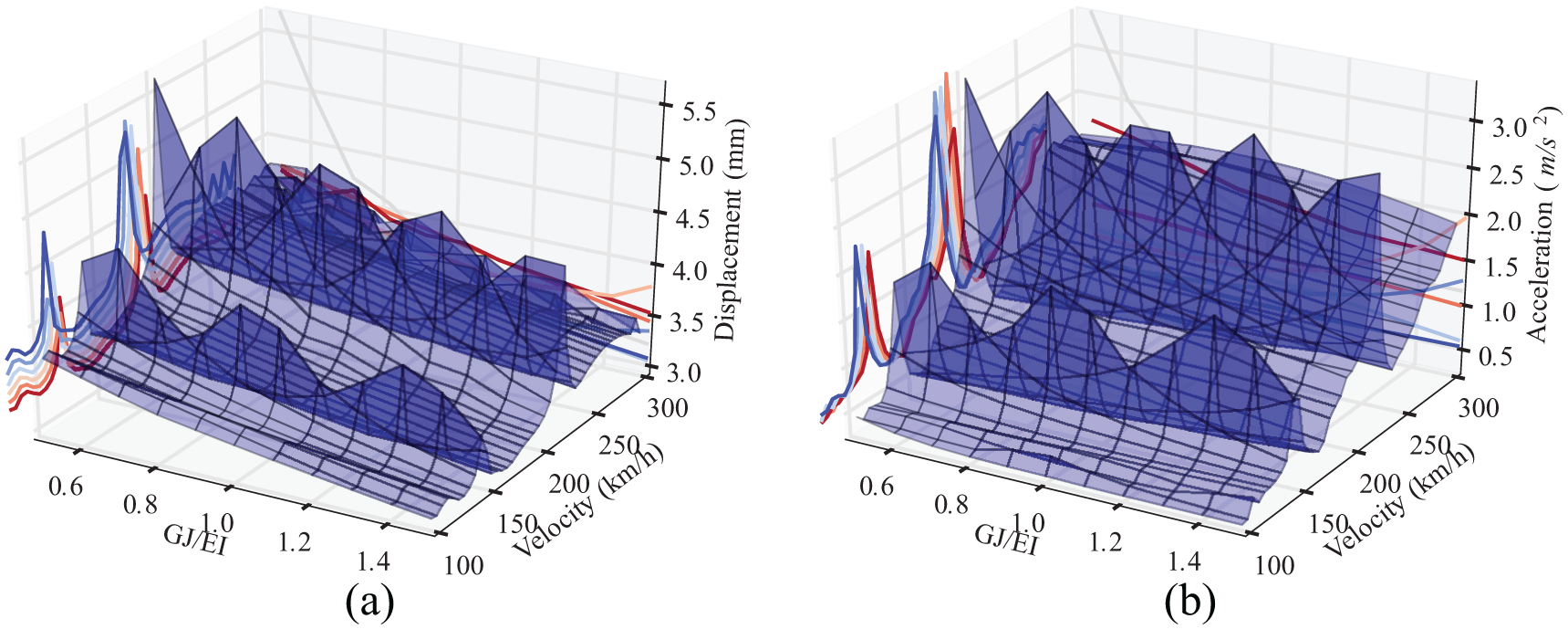
Effect of the torsional-to-flexural stiffness ratio on the maximum dynamic response for a skew angle of
Effect of span length
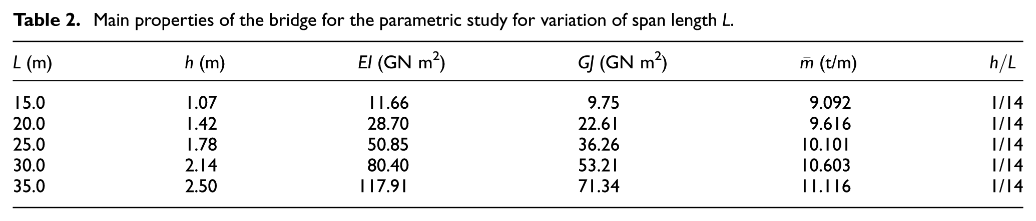
In this final parametric study, the influence of span length on the dynamic response of the simply supported skew bridge is carried out, ranging between
Main properties of the bridge for the parametric study for variation of span length L.
The first natural frequency corresponding to each span length is shown in Figure 15(a) for the different skew angles. In addition, the variation of the first natural frequency between the skew angles of 0 and 40 is presented in Figure 15(b). It can be observed that the variation of frequency for each span length increases with the skew angle
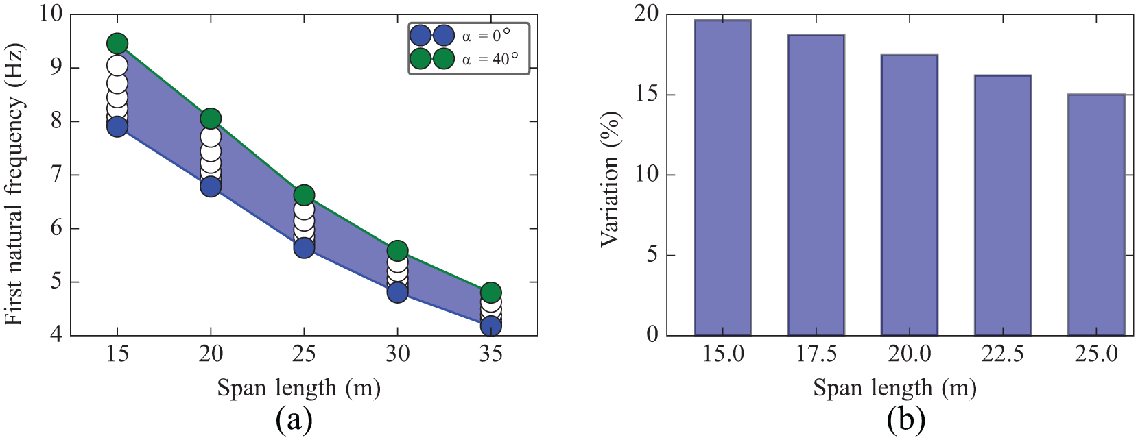
Influence of span length on the natural frequency of the simply supported skew bridge: (a) first natural frequency and (b) variation of frequency.
The results of the parametric study of the maximum response to the traffic loads is presented in Figure 16, showing the results corresponding to the main peak (second resonant velocity) for each span length. A direct comparison of all results as presented in previous studies (Figures 11, 13 and 14) is not meaningful, as the characteristics of bridges are different for each span length. The ratios of the maximum dynamic deflection to static deflection (dynamic amplification factor (DAF)) are presented in Figure 16(a), showing that the DAF decreases with the increasing span length. It is also observed that the range of variation of the DAF does not change significantly for different skew angles as the span length increases. However, for maximum accelerations (Figure 16(b)), a reduction in the range of variation of magnitude can be observed for different skew angles. It can then be remarked that the span length reduces the skewness effect on the dynamic response of the bridge in terms of maximum acceleration.
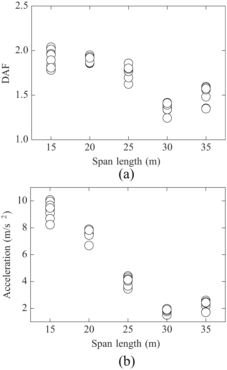
Maximum dynamic responses at mid-span: (a) maximum dynamic amplification factor (DAF) for deflections and (b) maximum acceleration.
Conclusion
In this article, analytical beam models for determining the dynamic response of simply supported skew bridges under moving loads have been proposed. These include a general model with bending and torsion and a simplified model including only bending in the vertical plane. Both models are based on the analytical determination of eigenfrequencies and eigenmodes taking into account the boundary conditions and orthogonality relationships. The dynamic response is obtained in the time domain following a piecewise exact integration. The resulting models are robust, accurate, simple to define and computationally efficient. They have been successfully validated comparing to the FE beam and shell models with numerical modal analysis. The application to parametric analyses of representative railway bridges under moving loads yield the following conclusions:
The analytical beam models proposed are suitable for simple and quick dynamic analyses, allowing for parametric calculations for massive amounts of cases.
The criterion for the estimation of critical (resonant) train velocities in CEN (2003) is basically valid also for simply supported skew bridges.
The degree of skewness of the bridge plays an important role in the dynamic behaviour of the bridge in terms of deflections, which decrease with the skew angle. However, the maximum accelerations are hardly affected by skewness.
There is a critical skew angle from which the effect of skewness is more noticeable; for the cross-section used in this parametric study, it was determined as
The torsional stiffness has a significant influence on the vibration of the bridge in terms of deflections when the skew angle is larger than the critical value. However, maximum accelerations are hardly affected.
For larger span lengths, the skewness effect on the dynamic behaviour is reduced, in terms of both changes in natural frequencies and maximum accelerations.
Footnotes
Appendix 1
Declaration of Conflicting Interests
The author(s) declared no potential conflicts of interest with respect to the research, authorship and/or publication of this article.
Funding
The author(s) disclosed receipt of the following financial support for the research, authorship and/or publication of this article: The authors are grateful to the support of MINECO of Spanish Government through the project EDINPF (Ref. BIA2015-71016-R) and to the support provided by the Technical University of Madrid, Spain.