
Abstract
This work investigated the impact performance of hollow reinforced concrete members with inner octagonal steel tube. Experiments on 13 specimens subjected to low-velocity drop weight impact are presented in this article, covering key parameters such as the impact height, boundary condition, axial load ratio and thickness of the inner tube. The dynamic processes, failure patterns, impact force and mid-span deflection histories, and residual mid-span deflections were obtained from the experiments. Flexure-shear was observed as the main failure pattern for all the specimens under impact. It was found that all the key parameters considered had influences on the impact performance of hollow reinforced concrete specimens with inner octagonal steel tube. Effects of these parameters on the impact performance of hollow reinforced concrete members were discussed.
Keywords
Introduction
Hollow reinforced concrete (HRC) members are economical designs and have been widely employed in many cases such as bridge piers. This is due to their relatively lower seismic load under earthquake contributed from the nature of lighter self-weight (An et al., 2013; Wang et al., 2018) compared to traditional reinforced concrete members. The HRC members are generally confined by both inner and outer transverse reinforcements, as presented in Figure 1(a). To improve the ductility and increase the construction speed of the piers, the HRC member with an inner steel tube was proposed (Kim et al., 2003) and has been increasingly used in bridge piers in recent years. Figure 1(b) illustrates the cross-section of an HRC pier with an inner octagonal steel tube employed in the Labajin Bridge in China (An et al., 2013; Wang et al., 2018). Due to the difficulties in manufacturing and transportation of large size circular steel tube, the octagonal tube manufactured by steel plates was chosen in this project to replace the conventional circular tube. This type of HRC member with an inner octagonal steel tube is termed as ‘HRC-OS member’ for simplicity in this article.
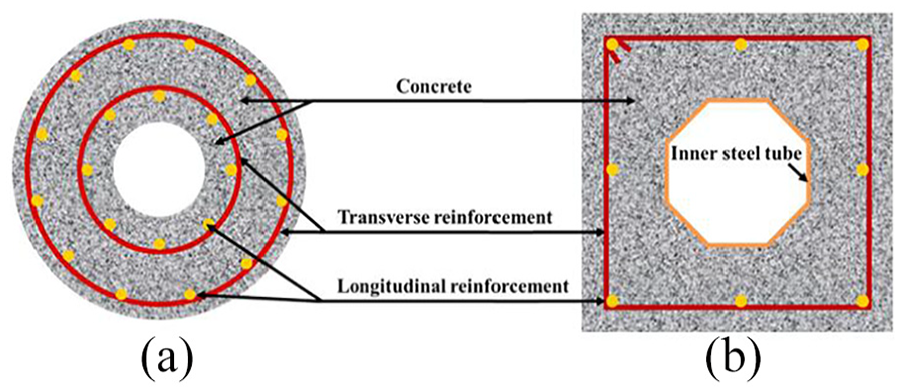
Cross sections of (a) HRC and (b) HRC-OS members.
Up until now, several studies (Han et al., 2008, 2010a, 2010b; Won et al., 2014) reported the effect of the inner circular steel tube on the compressive, seismic and fire performance of the HRC members. Available research results demonstrated that the HRC member with an inner circular steel tube had higher strength and ductility compared to the HRC member, which can be attributed to the strength of the inner circular tube as well as the high confining effect of the inner circular tube to the reinforced concrete section. For the HRC-OS member, Wang et al. (2018) studied the mechanical behaviour of the HRC-OS columns under axial and eccentric compression loading both experimentally and analytically. The authors concluded that the inner octagonal steel tube can work well with the outer reinforced concrete during the whole loading process. Based on the test results, a design method for the ultimate strength of the HRC-OS column was suggested.
During the whole lifecycle, structure members may be subjected to various load conditions such as the earthquake, fire and impact loading, in addition to bearing the compressive loading. Especially for the bridge piers and columns in super high-rise buildings, the impact loading is essential to be considered in the structure design. Several design codes, including ACI (1992), EN1991-1-7 (2010) and AASHTO (2014), have provided rules to consider the vehicle impacts as a type of accidental loads. Until now, considerable work has been conducted on the impact behaviour of steel (Nassirnia et al., 2018; Zeinnoddini et al., 2002; Zhang et al., 2018), reinforced concrete (Fujikake et al., 2009; Jiang et al., 2012; Pham and Hao, 2017, 2018) and composite members (Bambach et al., 2008; Hu et al., 2018; Qasrawi et al., 2015; Wang et al., 2013). The influence of some key parameters, such as impact energy, boundary condition, axial-load level, and material strength, on the impact behaviour of the members was evaluated. Some analytical methods were proposed to quantify the vulnerability of the members (Han et al., 2014; Thilakarathna et al., 2010; Zhang et al., 2018). So far, limited research has been conducted on the HRC-OS member subjected to low velocity impact loading, which is beneficial to the application of this new member.
In this context, the aim of this work is to experimentally investigate the impact behaviour of the HRC-OS members subjected to lateral impact loading, including the dynamic processes, failure patterns, impact force and mid-span deflection histories, and residual mid-span deflections. For this purpose, 13 HRC-OS specimens with two different inner steel tube thicknesses were fabricated. The impact heights of 2 and 5 m, and the axial-load levels of 0, 0.2 and 0.3 were chosen in this article. The influences of impact heights, boundary conditions, axial-load levels and tube thicknesses on the impact performance of HRC-OS members are discussed based on the experimental results.
Test procedure
Specimen preparations
Thirteen HRC-OS specimens having two different thicknesses of inner octagonal steel tube were tested. The geometric dimensions and rebar arrangements are presented in Figure 2. The octagonal steel tubes were manufactured from steel sheets with nominal thicknesses of 2 and 3.91 mm, respectively, and were seam-welded. All the specimens had the same dimensions and rebar arrangements. The physical length and width of the specimens were 1800 and 400 mm, respectively. Eight longitudinal bars with 15.6 mm diameter were employed, and the thickness of concrete cover measured from the external surface of the stirrups was 20 mm. Stirrups with a diameter of 7.7 mm were spaced at 100 mm in the 1000 mm central region of the specimen, as presented in Figure 2. Two square steel plates with a thickness of 20 mm were employed as end plates.
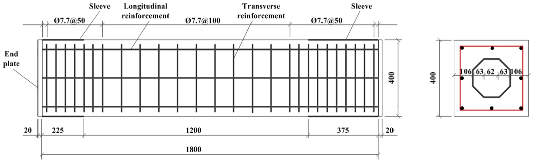
Details of HRC-OS specimens.
The HRC-OS specimens were fabricated in the following processes: the inner steel tube and the rebar cage were first installed inside the square steel mould at the designed geometric position; second, the concrete was poured into the gap between the inner tube and outer square tube; and finally, the outer square steel mould used for as the concrete formwork was removed after the concrete had hardened. Subsequently, specimens were placed in a laboratory room for curing until the impact test. The specimen photos taken during the fabrication process are presented in Figure 3.
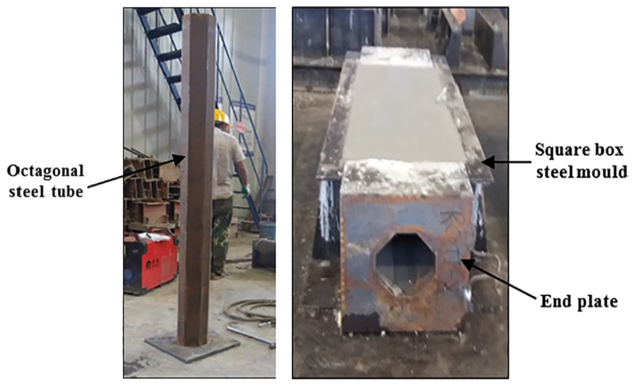
Specimen photos during the fabrication process.
Test details about all the specimens are given in Table 1, in which n represents the axial load ratio, ts represents the inner steel tube thickness, H represents the drop height, V0 represents the velocity of the impact hammer before the collision and E0 represents the impact energy. The identification system of the specimens is defined as follows:
The first letters ‘K’ and ‘N’ represent the HRC-OS specimens with thick-walled (3.91 mm) and thin-walled (2 mm) steel tube, respectively.
The letters ‘FF’, ‘FP’ and ‘PP’ denote the fixed–fixed, fixed–pinned and pinned–pinned ends, respectively.
The first numbers ‘2’ and ‘5’ account for the impact height.
The last numbers ‘0’, ‘0.2’ and ‘0.3’ represent the axial-load ratio. In this work, the influence of axial load ratio on the impact performance of the HRC-OS specimens was investigated. The load ratio is defined as
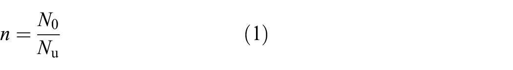
Where N0 represents the constant axial load applied in the impact test and Nu represents the ultimate compressive strength of the HRC-OS member determined by using the superposition method (Wang et al., 2018).
Details of all specimens.
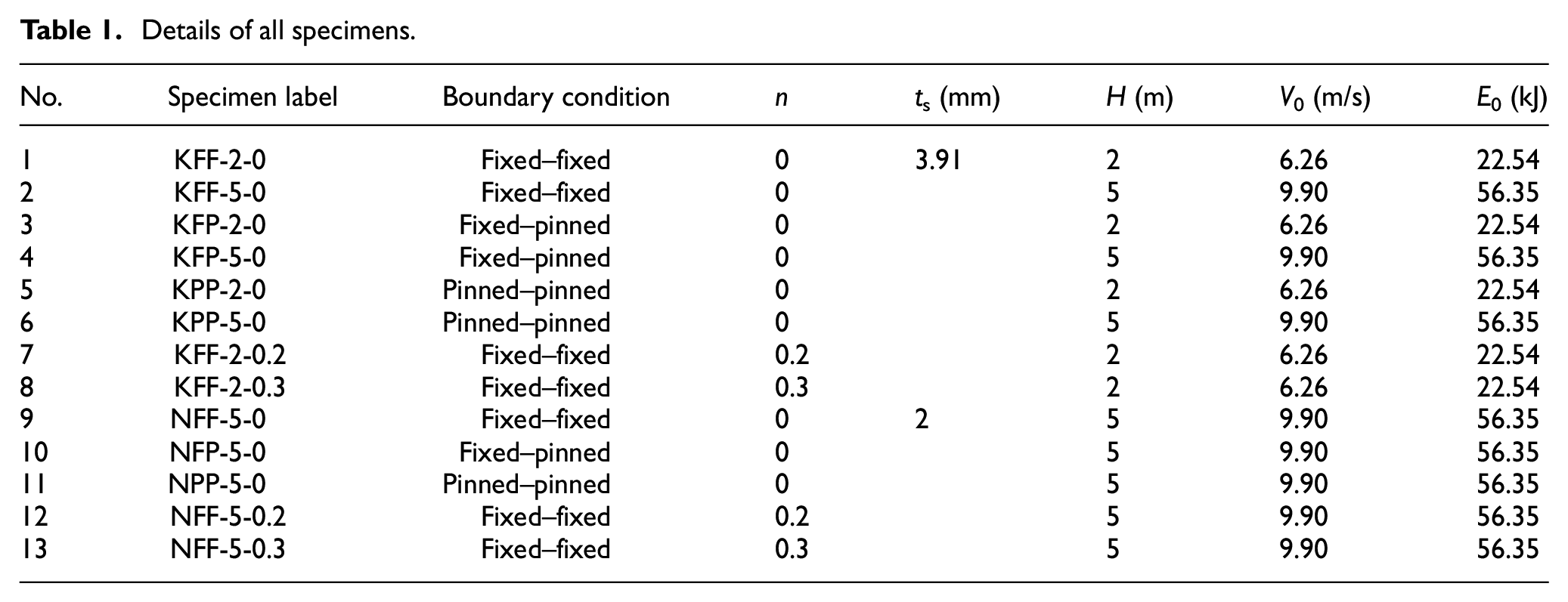
For example, KFF-2-0.2 stands for an HRC-OS specimen having a thick-walled steel tube (3.91 mm) and an impact height of 2 m, with both fixed ends and the axial load ratio as 0.2.
Material properties
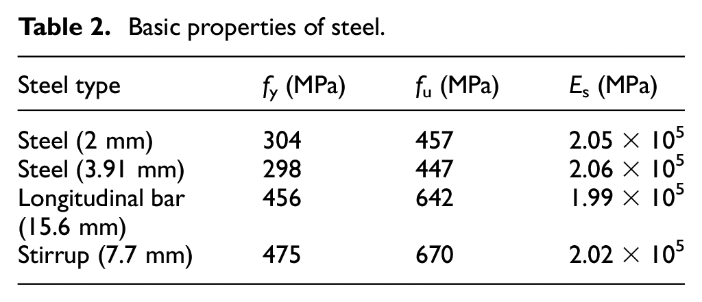
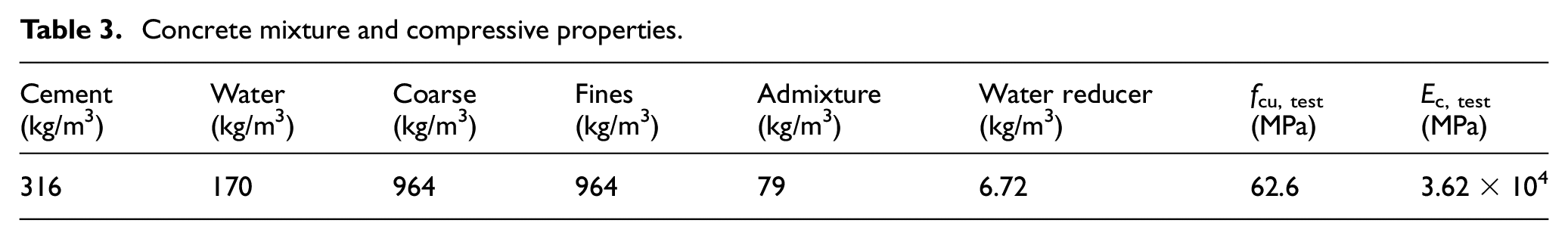
Material properties of all the steel elements were determined from the tensile tests in accordance with GB/T 228-2010 (2010). The tensile steel coupons were obtained from the steel sheets and rebars. Table 2 gives the yield strength fy, ultimate strength fu and elastic modulus Es for all the steel elements. The normal concrete mixture proportions, cubic compressive strength (fcu, test) and elastic modulus (Ec, test) on the date of impact testing are presented in Table 3.
Basic properties of steel.
Concrete mixture and compressive properties.
Test apparatus and procedure
The general drop weight impact method suitable for the testing of structure components was adopted in this article. The impact test was performed using the purpose-built impact machine at Taiyuan University of Technology, which can provide the axial loading and dynamic impact simultaneously, as presented in Figure 4. Details of the drop hammer and disc spring are presented in Figure 4(c) and (d). The drop hammer with a 450 mm diameter circular bottom surface is made of 40Cr steel (Figure 4(c)). In this study, the mass of the drop hammer was kept constant at 1150 kg, and impact heights of 2 and 5 m were chosen corresponding to the impact energies of 22.54 and 56.35 kJ, respectively (Table 1). Fixed boundary condition was achieved by connecting the specimens to the base and the top steel beams using four high-strength bolts. Each specimen was axially loaded at a rate of approximately 5 kN/s up to the estimated load. In order to keep the axial loading constant during the impact process, 60 annular disc springs with a thickness of 14 mm and a diameter of 250 mm were placed between the axial-load cell and the hydraulic jack, as presented in Figure 4(d). The axial load and the impact load were measured by the static load cell installed between the specimen and the disc springs and the dynamic load cell built in the hammer, respectively, during the test. The data of the impact force were automatically recorded by a high-frequency data logging system NI PXIe-1082. One camera was employed to record the impact process and track the pre-labelled point (Figure 4(a)) on each specimen at 4000 frames per second. The lateral mid-span deflection of the specimen versus time can then be obtained by tracking the pre-labelled point at the mid-span.
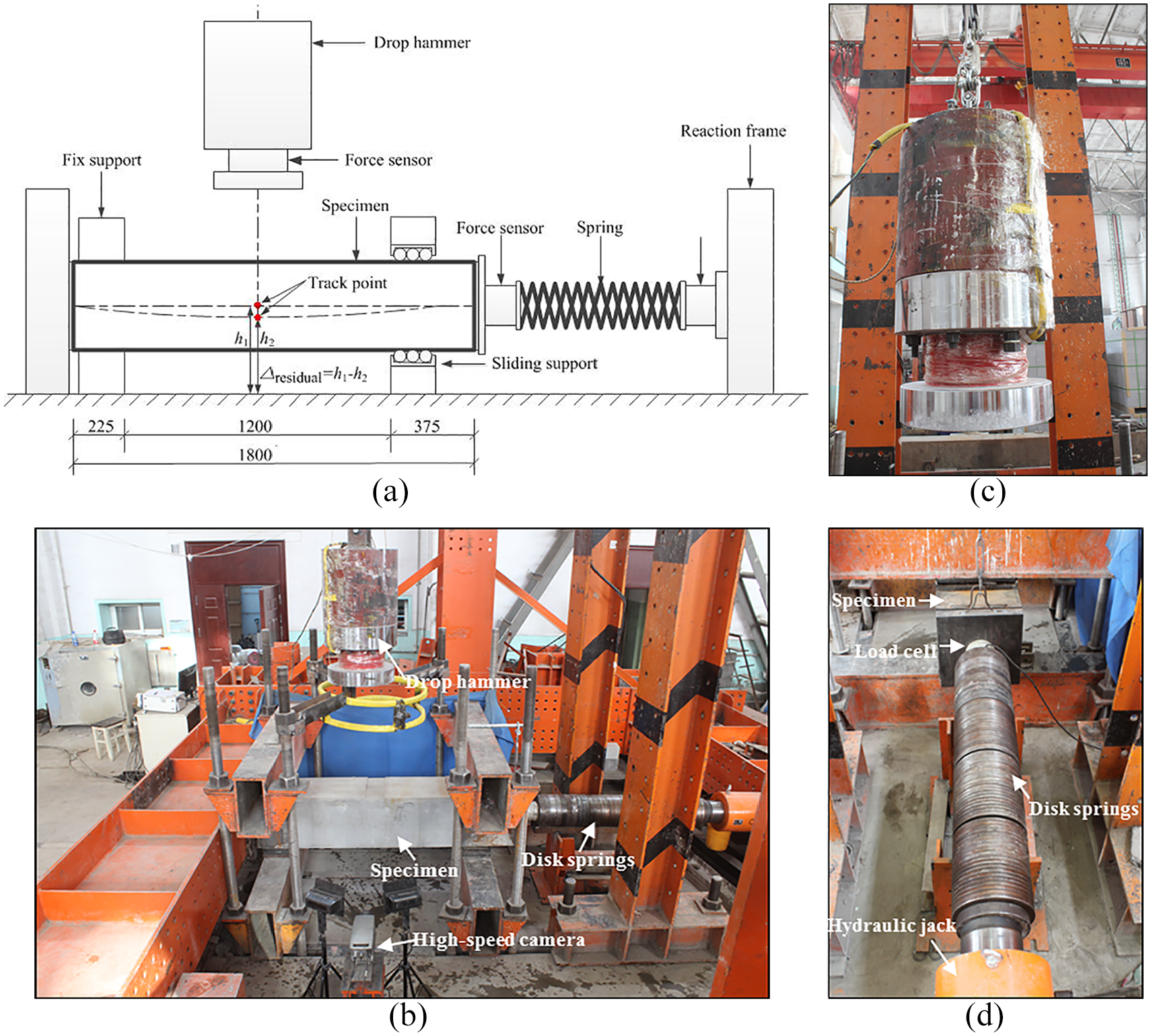
Test setup for drop hammer impact test. (a) schematic of test setup, (b) photo of test setup, (c) drop hammer and(d) axial loading equipment.
The impact test was conducted in the following process: the sample was first placed in the corresponding supporting fixtures; second, the axial loading was applied at the end of the sample; and finally, the hammer was lifted to the designed height and released along the slide rail to strike the sample at the mid-span. The secondary impact was found to have an insignificant effect on the impact response, thus no attempt was made to prevent the bouncing of the hammer on the sample. As mentioned previously, the weight (1150 kg) and the shape of the hammer were maintained unchanged, and the impact energy was varied by changing the drop height. The impact force, axial force and mid-span deflection histories were recorded during the impact testing. The height of the track point (presented in Figure 4(a)) to the floor before and after impact was measured by a height gauge tool to calculate the residual mid-pan deflection.
Results and discussion
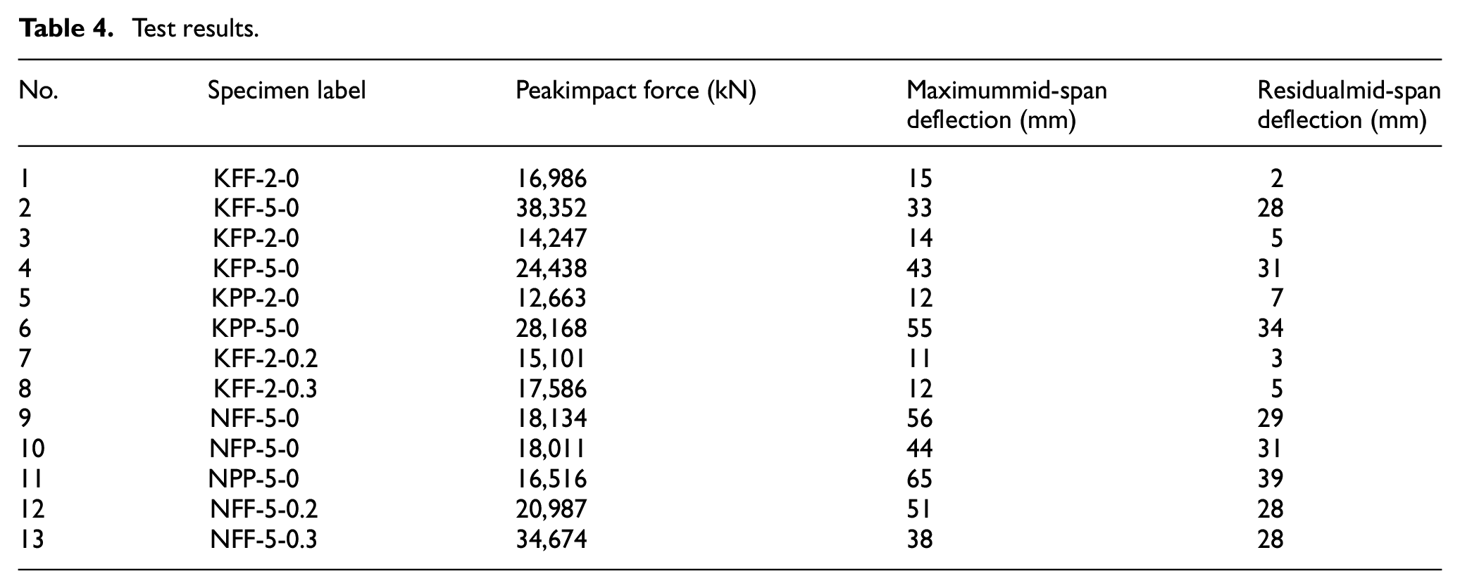
In this article, 13 HRC-OS specimens were tested under impact loads. Table 4 lists the peak impact forces, the maximum and the residual mid-span deflections of all specimens employed in this investigation. The whole dynamic processes, failure patterns, impact force and mid-span deflection histories and residual mid-span deflections obtained from tests are reported and discussed in this section.
Test results.
Dynamic process
The whole dynamic processes of all the specimens during the impact were recorded by the high-speed camera. The dynamic process of one of the specimens, for example, the KFF-5-0 specimen, is given as follows (Figure 5): (1) when t = 0.4490 s, the hammer contacted the specimen; (2) when t = 0.4495 s, the vertical and horizontal tensile cracks at the bottom of the specimen began to develop; (3) when t = 0.4497 s, the oblique cracks at fixed support were observed, and these cracks extended to the inner tube; (4) when t = 0.4510 s, the oblique shear cracks between the hammer and the fixed support were generated; (5) when t = 0.4537 s, the concrete at the mid-span of the specimen began to spall; and (6) when t = 0.4678 s, the hammer and the specimen separated until stationary condition. The whole dynamic process lasted for around 18.8 ms.
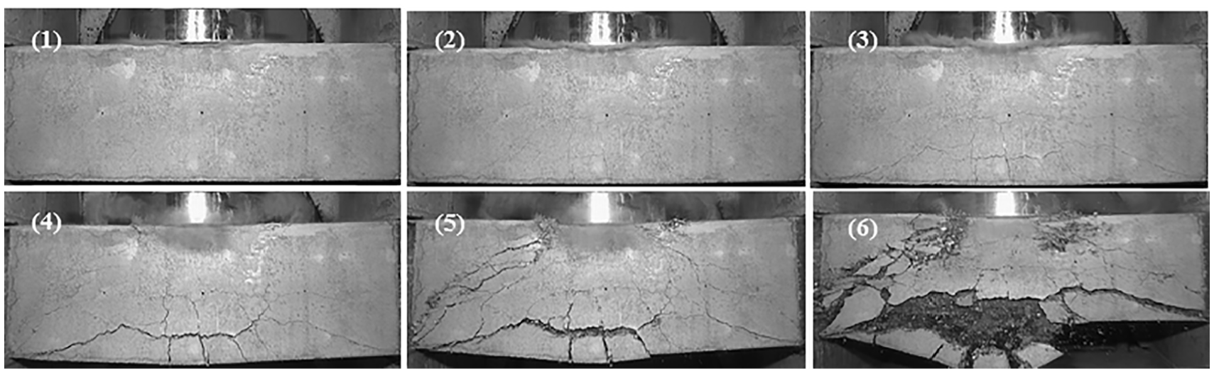
Dynamic process of KFF-5-0 specimen captured by high-speed camera.
The axial load was monitored by a load cell during the whole impact process, as presented in Figure 6. The axial load levels of 0.2 and 0.3 were chosen in this study. It can be found that the axial load-time curves fluctuated and showed a decreasing tendency, which was mainly induced by the axial shortening of the specimens. The axial load recovered slightly when the specimens rebounded. A ±15% deviation range is also given in Figure 6 to directly reflect the stableness of the axial load. The deviations of axial load were basically maintained within the ±15% range, which demonstrates that the loading system using disc spring could keep the axial loading generally constant during the impact process.
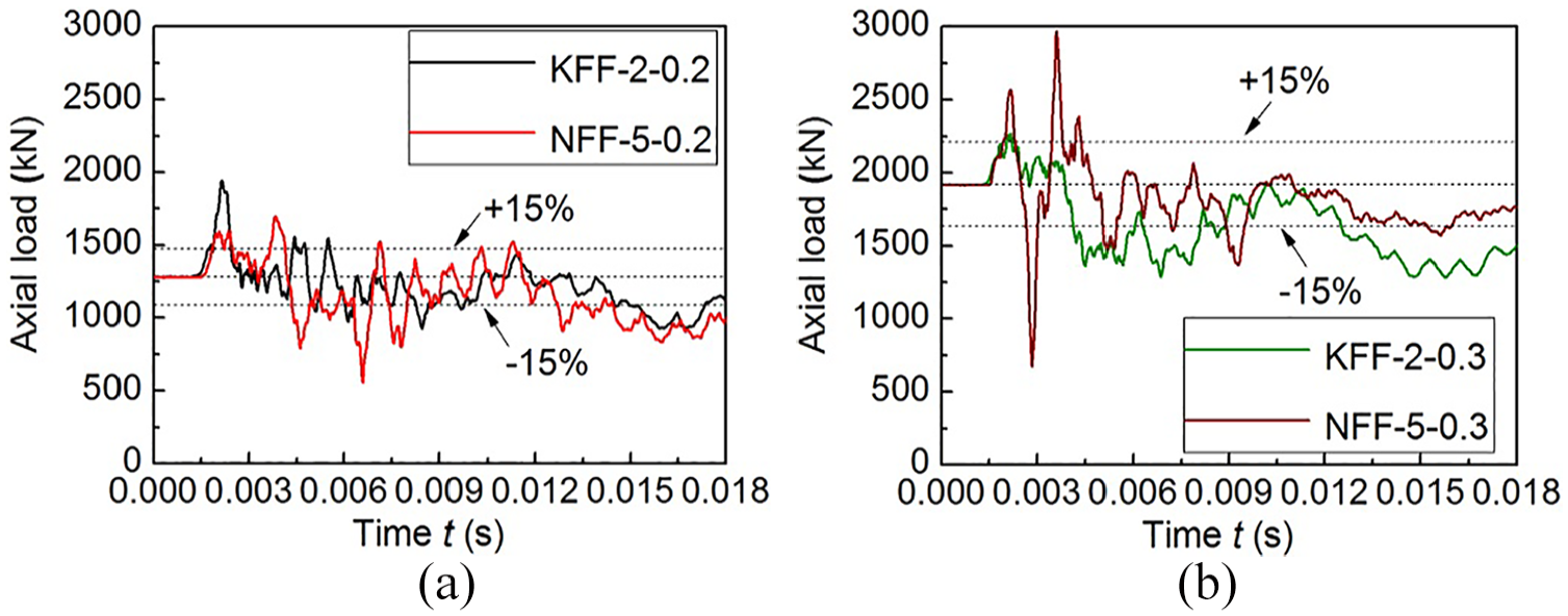
Time histories of axial load. (a) axial-load ratio n = 0.2 and (b) axial-load ratio n = 0.3.
Failure pattern
The failure patterns of all the HRC-OS specimens after the impact test are presented in Figure 7(a)-(c). In order to clearly reflect the failure patterns, Figure 7(d) gives the schematic view of typical failure patterns for HRC-OS specimens corresponding to the impact heights of 2 and 5 m, respectively. It can be observed that the specimens mainly exhibited flexure-shear failure pattern when the impact heights H was 2 or 5 m. As presented in the figure, the deflection increased when the impact height increased from 2 to 5 m. When the impact height was 2 m, the fine flexural and oblique cracks appeared on the surface of the specimens. When the impact height increased to 5 m, obvious flexural and oblique cracks and severe concrete spalling were observed.
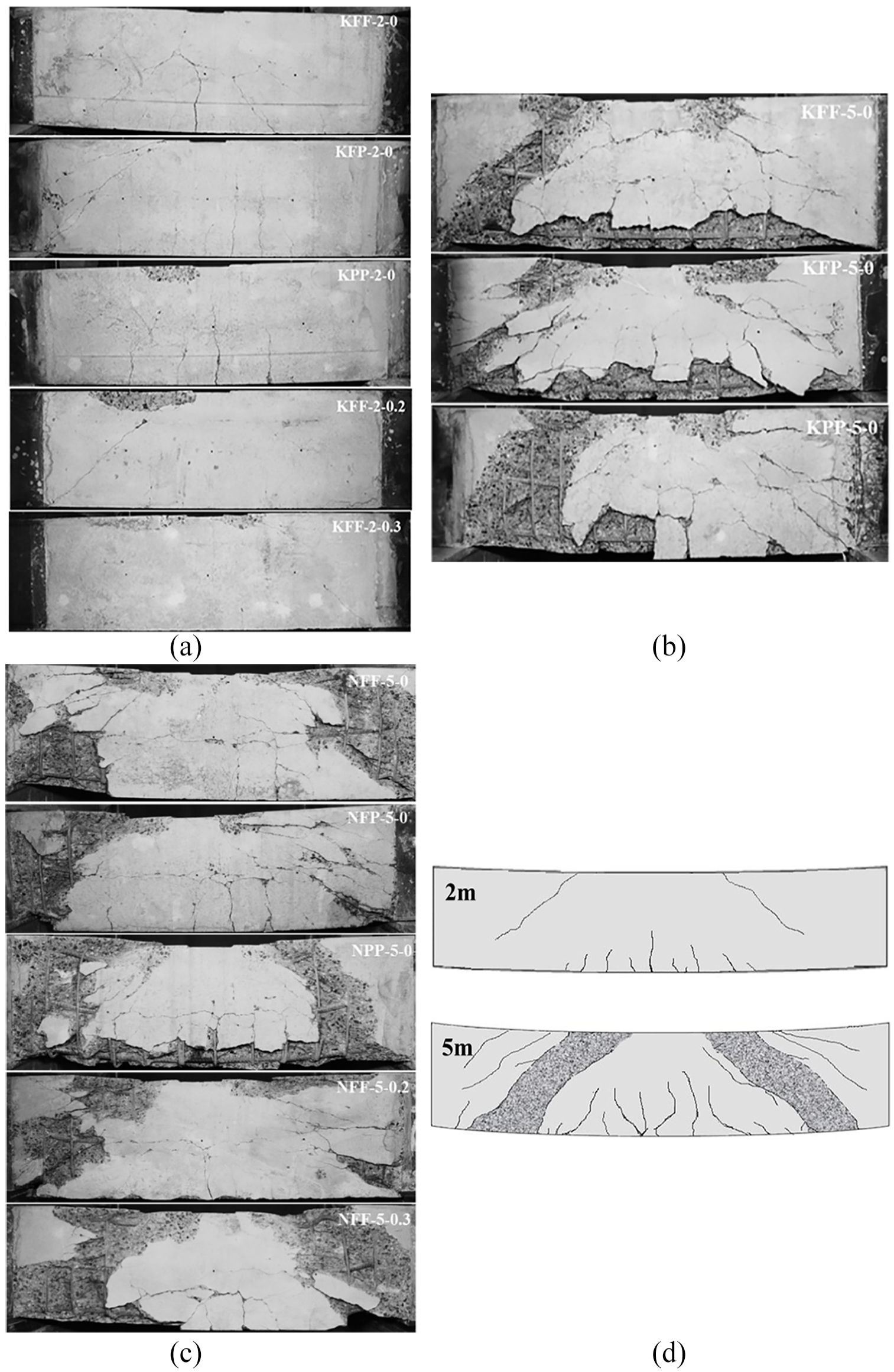
Failure patterns of HRC-OS specimens. (a) Series I (ts = 3.91 mm, H = 2 m), (b) Series II (ts = 3.91 mm, H = 5 m),(c) Series III (ts = 2 mm, H = 5 m) and (d) schematic view.
For specimens with the same impact height but different boundary conditions (e.g. KFF-2-0, KFP-2-0 and KPP-2-0), the oblique shear cracks were more obvious under fixed–fixed boundary condition, while fewer oblique cracks were observed under pined–pined boundary condition. For specimens with the 2-m impact height and fixed ends but different axial-load ratios (e. g. KFF-2-0, KFF-2-0.2 and KFF-2-0.3), the specimens with axial load had smaller deflection and fewer cracks than those without axial load, which meant that the axial load applied in this test had a positive effect on the impact resistance performance of the HRC-OS specimens. According to the comparison between Figure 7(a) and (c), it can be found that the axial load had a more obvious influence on the flexural cracks under 2-m impact height than the shear cracks under 5-m impact height. The axial load effectively improved the capacity of HRC-OS specimen to resist the development of flexural cracks. Comparisons of the failure patterns between specimens with tube thicknesses of 3.91 and 2 mm (e.g. Figure 7(b) and (c)) showed that the thickness of inner steel tube had no significant influence on the failure mode of HRC-OS specimens under lateral impact.
Impact force
The impact force histories between the specimen and the hammer are given in Figure 8. Details of the peak impact force corresponding to different cases are presented in Table 4. The peak impact force of the HRC-OS specimens was in the range of 12,663–38,352 kN when the impact energy E0 was 22.54 and 56.35 kJ, respectively. As presented in the figures, the impact force versus time of all the specimens exhibited similar trends. The impact force was increased linearly with time until the first peak and was then decreased steeply. The duration of the first impulse was about 0.5 ms independent to the impact height and boundary condition. After the first peak, several local peaks were observed before the impact force gradually decreased to zero. There was no obvious platform in the impact force-time curves. Similar trends in impact force with time were observed in the reinforcement concrete specimens (Pham and Hao, 2017; Tachibana et al., 2010).
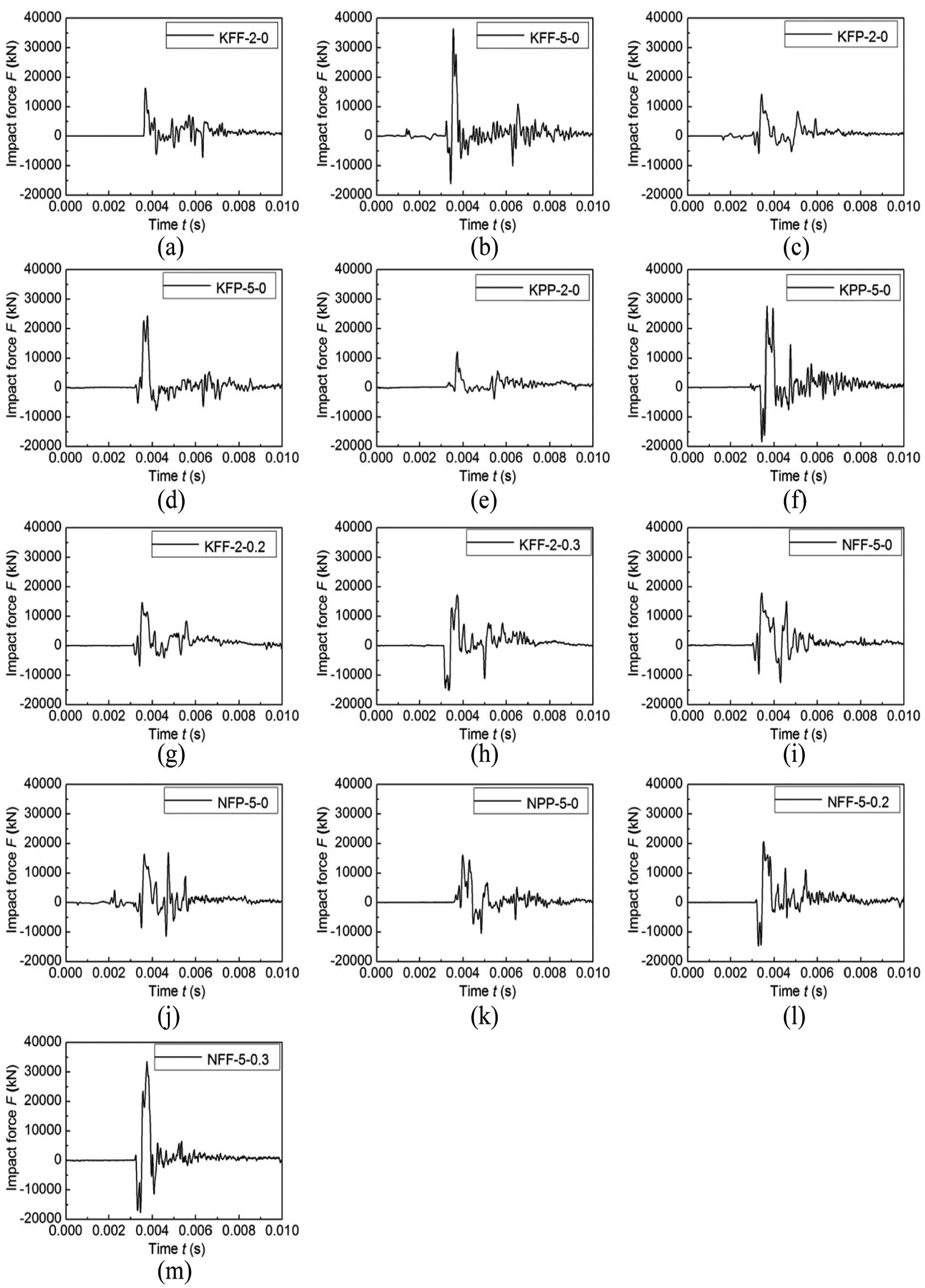
Time histories of impact force. (a) KFF-2-0, (b) KFF-5-0, (c) KFP-2-0, (d) KFP-5-0, (e) KPP-2-0, (f) KPP-5-0, (g) KFF-2-0.2, (h) KFF-2-0.3, (i) NFF-5-0, (j) NFP-5-0, (k) NPP-5-0, (l) NFF-5-0.2 and (m) NFF-5-0.3.
The peak impact force of the specimen could reflect its resistance capacity under impact loading. Effects of impact height, boundary condition, axial load and inner tube thickness on the peak impact force of the HRC-OS specimens are illustrated in Figure 9. It can be seen from Figure 9(a) that the peak impact force increased with the increase of the impact height. For instance, for KFP specimens with no axial load, the peak impact force increased from 14,247 kN to 24,438 kN when the impact height increased from 2 to 5 m. This increase in the impact force was mainly due to the larger impact energy. Figure 9(b) shows that the specimens with both ends fixed presented the largest impact force as compared to the specimens with fixed–pinned and pinned–pinned ends. For example, the impact force of the specimen KFF-2-0 increased by 16.1 and 25.5% compared to that of the specimens KFP-2-0 and KPP-2-0, respectively. This was mainly because that boundary condition affected the global stiffness of the specimens, which was related to the maximum impact force. The effect of the axial load level was significant on the peak impact force when subjected to the impact height of 5 m (Figure 9(c)). With the axial load level increased from 0 to 0.3, the peak impact force increased by 91.2% under the impact height of 5 m. This phenomenon was similar to the performance of the reinforced concrete members subjected to the combined compression and bending/shear: as the relatively low axial-load level increased, the bending/shear resistance of the member increased. From Figure 9(c), it also can be found that the effect of the axial-load ratio is more sensitive on the peak impact force of the specimens with thinner internal steel tube. Related research shows that the peak impact force is generally influenced by the impact energy and the contact stiffness between the specimen and hammer (Pham and Hao, 2016; Wang et al., 2015). In this article, the peak impact force is affected by the concrete stiffness due to the direct contact between the external concrete of the specimen and the hammer. Under the same axial-load ratio, concrete is assigned more compression load for the specimen with a thinner inner steel tube, and the flexural stiffness of the reinforced concrete increases more obviously. Therefore, the change in the contact stiffness between the external concrete and the hammer may be the reason for the difference in the response of peak impact force between the specimens with thin and thick inner steel tubes. As shown in Figure 9(d), the peak impact force increased (by 35.7%, i.e. KFP-5-0 and NFP-5-0) when the thickness of the inner steel tube increased. Naturally, more steel in the cross section can enhance the impact resistance of the specimens. Based on the above analysis, the peak impact force of the HRC-OS members was obviously influenced by the impact energy (impact height) and contact stiffness (boundary condition, axial-load ratio, specimen stiffness et al.).
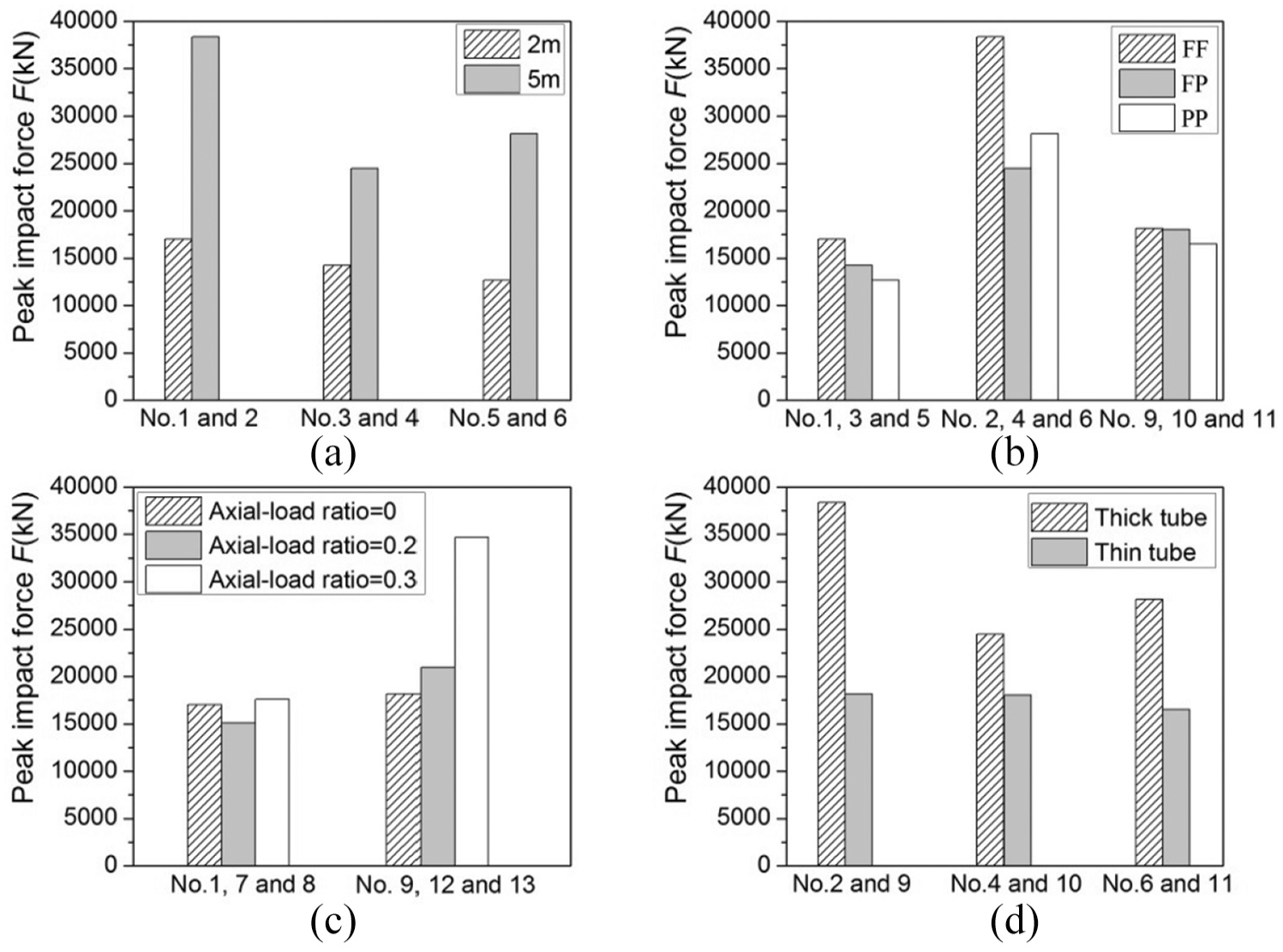
Effects of key parameters on the peak impact force. (a) Effect of impact height, (b) effect of boundary condition, (c) effect of axial load and (d) effect of inner tube thickness.
Mid-span deflection
Figure 10 presents the mid-span deflection histories during the impact, which was obtained from the displacements of the tracked point captured by the high-speed camera. Details of the maximum and residual mid-span deflections are given in Table 4. The maximum mid-span deflections under different conditions were within a range from 11 to 65 mm. As illustrated in Figure 10, all curves presented similar trends under different experimental parameters, that is, the mid-span deflection increased linearly after the impact; the deflection continued to increase up to the maximum value, while its growth rate decreased due to the consumption of the kinetic energy; then the deflection decreased to a constant value because of the release of the elastic energy of the specimens. As shown in Figure 10(n), the slope of ascending part of the mid-span deflection versus time curves increased with the increase of the impact height, and the specimen with pinned–pinned ends presented a larger slope when the impact height was 5 m.
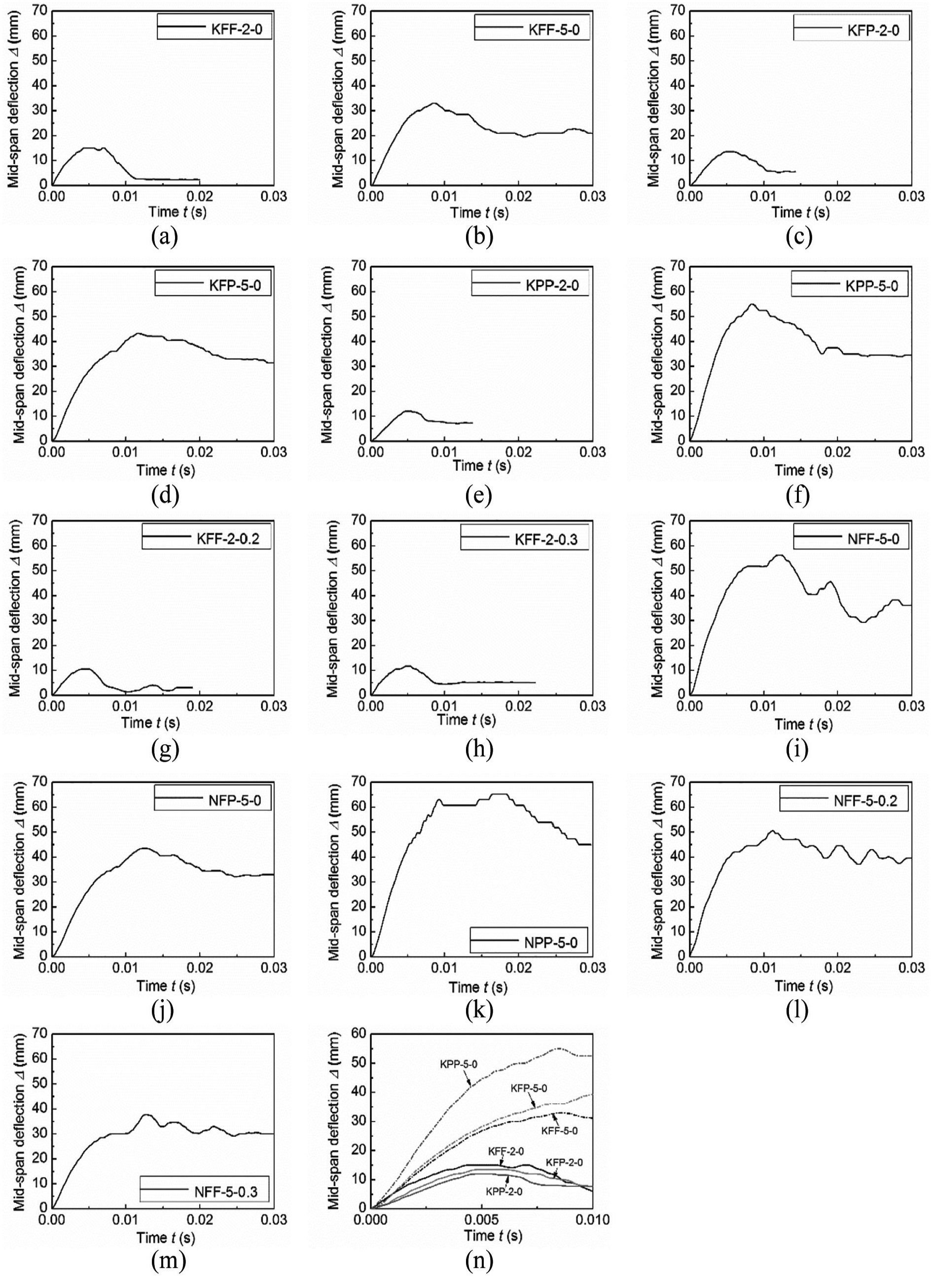
Time histories of mid-span deflection. (a) KFF-2-0, (b) KFF-5-0, (c) KFP-2-0, (d) KFP-5-0, (e) KPP-2-0, (f) KPP-5-0,(g) KFF-2-0.2, (h) KFF-2-0.3, (i) NFF-5-0, (j) NFP-5-0, (k) NPP-5-0, (l) NFF-5-0.2, (m) NFF-5-0.3 and (n) Comparisons.
The residual deflection could directly reflect the impact damage degree to the structure members, thus Figure 11 emphatically presents the effects of key parameters on the residual mid-span deflection after being subjected to impact. The residual deflections were measured by a height gauge tool. It was reasonable that the residual mid-span deflections increased with the increasing impact height, as presented in Figure 11(a). For instance, after being subjected to impact from 2 and 5 m height, the residual deflections of the KFP specimens without axial load were 5 and 31 mm at mid-span, respectively. According to the bar chart of Figure 11(b), specimens with both fixed ends showed the minimal residual deflection at mid-span when compared to those with fixed-pinned and pinned–pinned ends. For example, when the impact height was 5 m, the residual mid-span deflections for the specimens with 2 mm inner steel tube were 29, 31 and 39 mm for fixed–fixed, fixed–pinned, and pinned–pinned ends, respectively. This indicated that the impact resistance of the HRC-OS specimens increased by restraining the end rotation. From Figure 11(c), the axial-load level had an unobvious effect on the residual mid-span deflections. As the axial-load level increased from 0 to 0.3 under the impact height of 5 m, the residual mid-span deflection decreased by only 3.4%. The effect of the inner tube thickness is presented in Figure 11(d). It can be found that the residual mid-span deflection showed a decreasing trend with the increase of the tube thickness (the maximum decreasing amplitude of 12.8% for Specimens NPP-5-0 and KPP-5-0), which was mainly due to the higher impact resistance induced by increased steel ratio. Within the range of parameters reported in this study, the boundary condition had a more significant effect on the impact resistance of the HRC-OS members, compared to other parameters, that is, the axial-load ratio and the thickness of the inner tube.
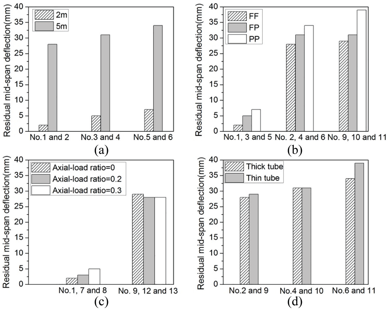
Effects of key parameters on the residual mid-span deflection. (a) Effect of impact height, (b) effect of boundary condition, (c) effect of axial load and (d) effect of inner tube thickness.
In order to understand the whole dynamic response of the HRC-OS members during impact, Figure 12 presents the normalized curves of F/Fmax–t and Δ/Δmax–t, in which F and Δ represent the impact force and the mid-span deflection, respectively, and Fmax and Δmax denote the peak values of them. Specimens KFF-2-0 and KFF-5-0 were selected as examples for analysis. As presented in the curves, there were basically three stages for the dynamic response, as described below:
During the first stage (Point o-Point a), the impact force increased rapidly to its peak value (Point a), whereas corresponding mid-span deflection of the HRC-OS members was small. At this stage, the impact force was mainly resisted by the inertia force of the specimen.
At the second stage (Point a-Point b), the impact force decreased rapidly after reaching Point a, and then decreased and fluctuated to Point b. Corresponding mid-span deflection increased to the peak value (Point b). During this stage, the specimen and the hammer moved down together, and the flexural and shear cracks were fully developed. The impact energy of the hammer was mainly dissipated by the crack propagations and specimen deformations.
At the last stage (Point b-Point c), the impact force fluctuated around zero and corresponding mid-span deflection decreased to a constant value. At this stage, the specimen rebounded and the elastic energy stored in the specimen was released.
Above full-range analysis may be used to directly reflect the energy transformation and dissipation of typical HRC-OS members during impact.
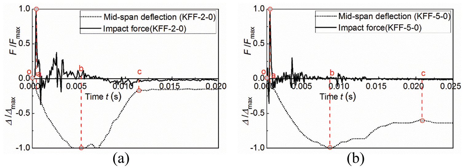
Time histories of F/Fmax and Δ/Δmax. (a) KFF-2-0 and (b) KFF-5-0.
Conclusion
This work investigated the impact performance of HRC members with octagonal inner steel tube under low-velocity lateral impact. Thirteen large-scale specimens with two different inner tube thicknesses were conducted under 2 different impact energy levels. Boundary conditions and axial load ratios were also considered. The whole dynamic processes, failure patterns, impact force and mid-span deflection histories and residual mid-span deflections obtained from the experiments were discussed.
The whole dynamic processes of the HRC-OS specimens were described in detail, and the flexure-shear failure patterns for the test specimens were observed under impact loading. The impact force-time curves showed a main peak and several local peaks, and the mid-span deflection-time curves exhibited ascending, descending and platform portions. Based on the experimental results, the impact height (impact energy) had a significant influence on the impact response. As the impact height increased, the peak impact force and residual mid-span deflection increased obviously. Within the parameters of this study, the effects of boundary condition, axial-load ratio and inner tube thickness on the peak impact force of HRC-OS members were obvious. The boundary condition had a more significant influence on the residual mid-span deflection than the effects of axial-load ratio and inner tube thickness.
Finally, the above experimental findings may be employed as a guidance for investigating this innovative composite member, though limited number of experiments were considered in this study. Complementary numerical and theoretical analysis are required on the performance of HRC-OS members under later impact in future studies.
Footnotes
Declaration of Conflicting Interests
The author(s) declared no potential conflicts of interest with respect to the research, authorship, and/or publication of this article.
Funding
The author(s) disclosed receipt of the following financial support for the research, authorship, and/or publication of this article: The authors gratefully acknowledge the National Natural Science Foundation (No. 5183000002) for the financial support.