
Abstract
Fibre-reinforced polymers have been increasingly used to strengthen reinforced concrete structures. However, premature brittle debonding failures may occur at the ends of externally bonded fibre-reinforced polymer laminates due to interfacial stress concentrations caused by stiffness imbalances. Although many studies exist on fibre-reinforced polymer-strengthened simply supported beams and slabs, the interfacial stress distributions in fibre-reinforced polymer-strengthened cantilever members are very different from those in simply supported members. Based on the assumptions of linear elasticity, deformation compatibility and static equilibrium conditions, the interfacial stresses in fibre-reinforced polymer-strengthened reinforced concrete cantilever members under arbitrary linear distributed loads were analysed. In particular, closed-form solutions were obtained to calculate the interfacial stresses under either a uniformly distributed load or a single concentrated load located at the overhanging end of the cantilever member. Existing test results on cantilever slabs strengthened by carbon fibre–reinforced polymer sheets were used to verify the model. According to the parametric analysis, the maximum interfacial stresses can be reduced by decreasing the fibre-reinforced polymer thickness, increasing the fibre-reinforced polymer bonding length and increasing the adhesive layer thickness, and by using less rigid fibre-reinforced polymer laminates with high tensile strengths. These results are useful for engineers seeking to optimize strengthening design parameters and implement reliable debonding prevention measures.
Introduction
Externally bonding fibre-reinforced polymer (FRP) laminates to reinforced concrete (RC) structural members, such as beams, slabs, walls and columns, is a convenient and efficient rehabilitation approach. This implementation of FRP laminates has been widely accepted in recent decades because FRP materials have a multitude of superior properties, including high strength-to-weight ratios, negligible section enlargements, easy installation and good durability (Aravind et al., 2013; Bakis et al., 2002; He et al., 2007, 2017; Qeshta et al., 2016). Many studies on FRP-strengthened flexural members have demonstrated that both their strength and stiffness increase significantly after strengthening. However, the strengthening effectiveness and mechanical behaviour of the strengthened beam or slab are greatly affected by the interfacial bond performance (Achillopoulou et al., 2016; Gao et al., 2007; Kim et al., 2015; Sayin and Manisali, 2010; Tounsi and Benyoucef, 2007; Xie et al., 2017). When the interfacial principal stress exceeds the bond strength of the FRP/concrete interface, premature brittle debonding failure may occur unless reliable additional anchoring measures (Oller et al., 2011; Smith and Teng, 2002; Teng and Chen, 2008; Zhou et al., 2017a, 2017b) are provided. Laminate end-debonding is one of the most common premature failure modes, which initiates at one of the laminate ends due to high interfacial shear and normal stresses induced by discontinuities (Deng et al., 2018; Gao et al., 2007; Narayanamurthy et al., 2012; Toutanji et al., 2007; Wang et al., 2018; Yao and Teng, 2007). Generally, the FRP strain at end-debonding failure is only approximately 30%–60% of its rupture strain, and thus the excellent mechanical performance of the FRP cannot be fully utilized (Biscaia et al., 2018). Hence, accurate prediction of the FRP-to-concrete interfacial stresses is essential for understanding the premature failure mechanism and achieving reliable and rational designs of anti-debonding measures for externally bonded FRP-strengthened structures.
Although attention has been given to interfacial stresses in FRP-strengthened simply supported members (Abdelouahed, 2006; Colombi et al., 2014; Daouadji et al., 2016; Edalati and Irani, 2011; He and Zhou, 2005; Sayin and Manisali, 2010; Smith and Teng, 2001; Tounsi and Benyoucef, 2007; Yang and Ye, 2010), few studies have focused on FRP-strengthened cantilever members (Akbarzadeh and Maghsoudi, 2010; Teng et al., 2001; Wan, 2016; Yang and Mao, 2018; Zheng et al., 2012). RC cantilever members, such as beams or slabs used in canopies, balconies and bridges, are typically used in outdoor structures and directly exposed to harsh environments, and thus they have severe durability problems. Moreover, if the steel reinforcing bars in cantilever members are prone to deviate from their designed positions, the cantilever members will very likely encounter sudden catastrophic failure when the load-carrying capacity is reached. More importantly, the interfacial bond behaviour and stress distribution in FRP-strengthened cantilever members are different from those in simply supported members. The flexural direction of a cantilever member is opposite to that of the vertical load. When the arbitrary linear distributed vertical load is applied along with the cantilever length direction, the section is closer to the free cantilever end, the bending moment is smaller but the deflection is greater. Therefore, interfacial stress analyses are important to reveal the damage mechanisms in FRP-strengthened cantilever structures and to provide a reference for the engineering applications of such structures.
In this study, interfacial stresses in RC cantilever members with FRP laminates are theoretically studied. Based on the conditions of static equilibrium and deformation compatibility, a linear elastic analytical model is developed to predict the distribution of interfacial stresses in a FRP-strengthened RC cantilever member under an arbitrary linear distributed load. The closed-form expressions under either a uniformly distributed load (UDL) or a single concentrated load (SCL) at the overhanging end of the cantilever are further determined to calculate the interfacial shear and normal stresses. Existing test results on cantilever slabs strengthened by carbon fibre–reinforced polymer (CFRP) sheets were used to verify the proposed model. Finally, a parametric analysis is carried out based on the theoretical model. The influences of various strengthening parameters, such as the FRP thickness, FRP bond length, adhesive layer thickness and FRP elastic modulus, on the interfacial stresses are discussed. The results could provide a good reference to cantilever member strengthening designs and engineering applications.
Theoretical model
Externally bonded FRP laminates should be reliably anchored at the fixed end of the RC cantilever members due to the maximum negative bending moment (Teng et al., 2001), as shown in Figure 1. Without the fixed-end anchorage, the strengthening effect could be insignificant since the debonding could be initiated when the load is small. In this article, only the case with anchorage at the fixed end is studied due to the engineering application significance. Because the magnitude of the negative bending moment decreases by a cubic function with increasing distance to the fixed end under arbitrary linear distributed loads, it is sometimes unnecessary to extend the bonded FRP laminates to the free end in economical designs. In this case, the level of stress concentration at the free laminate end increases obviously as the FRP bond length decreases, which may initiate the aforementioned end-debonding failure at the free laminate end. Therefore, even if the FRP laminates are reliably anchored at the fixed end, it is equally necessary to pay close attention to the interfacial stress distributions in FRP-strengthened cantilever members, especially their maximum values at the free laminate end.
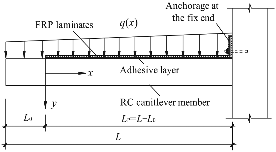
RC cantilever member strengthening with FRP laminates.
Basic assumptions
To simplify the theoretical derivations of interfacial stresses in FRP-strengthened cantilever members, the following assumptions are adopted in this article.
The composite materials, including concrete, adhesive layer and FRP laminates, are all linear elastic.
The average cross-sectional strain in bending conforms to the plane-section assumption before and after strengthening.
There is no slip at the FRP-to-adhesive interface or at the adhesive-to-concrete interface before debonding failure.
The shear and normal stresses in the adhesive layer are constant through the thickness, and the in-plane bending stiffness of the adhesive layer is neglected.
In the derivation of interfacial shear stress, the moment curvatures of both the cantilever member and the externally bonded FRP laminates are equal.
Interfacial shear stresses
Figure 2 shows a typical infinitesimal element of an FRP-strengthened cantilever member under an arbitrary linear distributed load q(x), in which τ(x) and σ(x) are used to denote the interfacial shear and normal stresses, respectively. The denotations for the applied load and corresponding internal forces and their positive sign conventions are also shown in Figure 2.
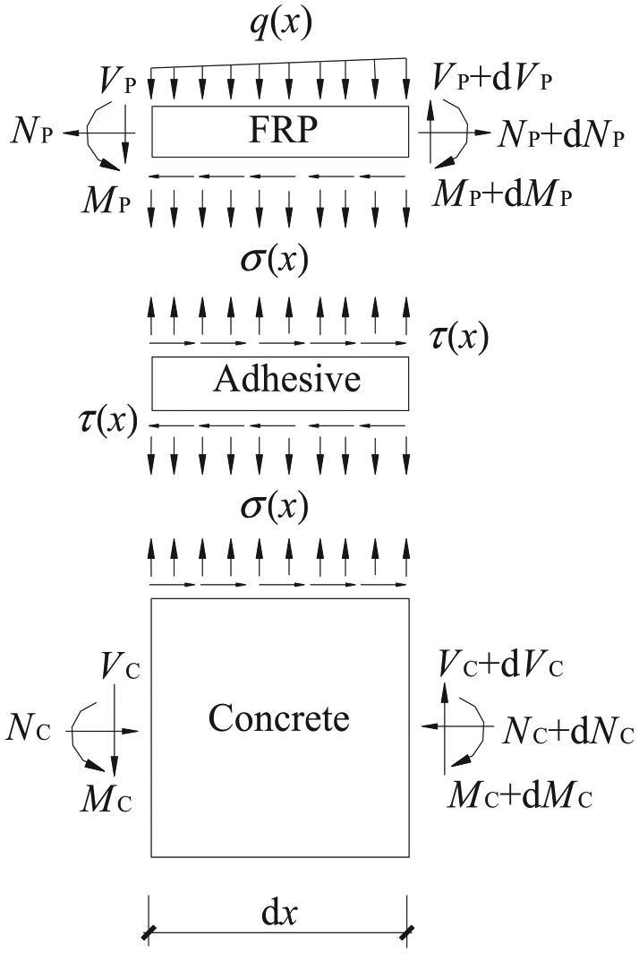
Forces in an infinitesimal element of an FRP-strengthened RC cantilever member.
According to the basic assumption 4, the interfacial shear stress τ(x) in the adhesive layer at any section x defined in Figure 1 can be expressed by
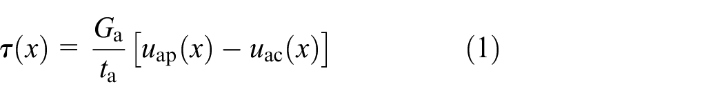
where uap(x) and uac(x) denote the longitudinal horizontal displacements at the bottoms of the FRP laminates and the top of the RC cantilever member, and Ga and ta denote the shear modulus and the thickness of the adhesive layer, respectively.
By differentiating equation (1) with respect to x, the strains at the bottoms of the FRP laminates εap(x) and the top of the RC cantilever member εac(x) can be expressed as follows
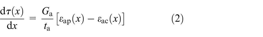
Taking into account the bending, shear and axial deformations of the concrete, FRP and adhesive layer, the strains εap(x) and εac(x) can be written as
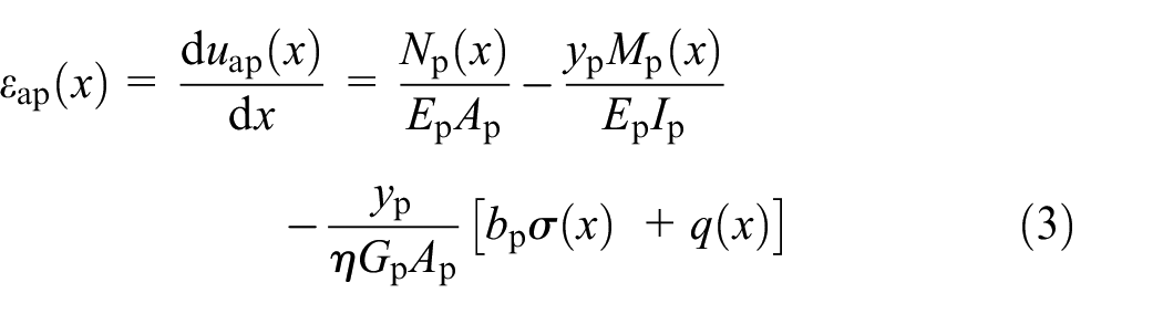

where Ep, Gp, Ec and Gc are the elastic and shear moduli of the FRP and concrete, respectively; Mp(x), Np(x), Mc(x) and Nc(x) are the bending moments and axial forces in the FRP and cantilever member, respectively; bp, Ap and Ip denote the width, the cross-sectional area and rotational inertia of the FRP, respectively; Ac and Ic denote the equivalent cross-sectional area and rotational inertia of the cantilever member, respectively; yp and yc are the distances from the bottoms of the FRPs and the top of the cantilever member to their respective centroids; and η, Timoshenko’s shear coefficient, is equal to 5/6 for a rectangular section (Smith and Teng, 2001).
Based on assumption 5 and the static equilibrium condition of the infinitesimal element in Figure 2, the relationships between the moments and axial forces in the cantilever member and FRP laminates can be expressed as follows

where M(x) is the total bending moment at any section x in the FRP-strengthened cantilever structure.
By neglecting the effects of shear deformations in both the cantilever member and FRP laminates on the interfacial normal stress (Smith and Teng, 2001), the governing differential equation for the interfacial shear stress is obtained by substituting equations (3) to (7) into equation (2) and differentiating the resulting equation
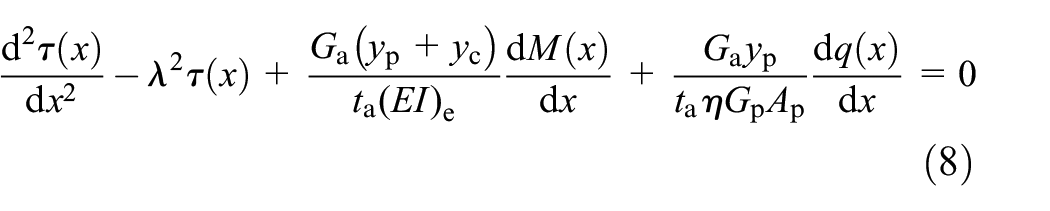
where
The general solution to equation (8) is

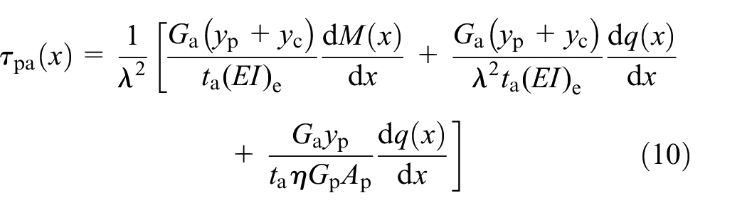
Because the second- and higher-order derivatives of the arbitrary linear distributed load q(x) with respect to x become zero, the particular solution τpa(x) in equation (9) can be expressed as
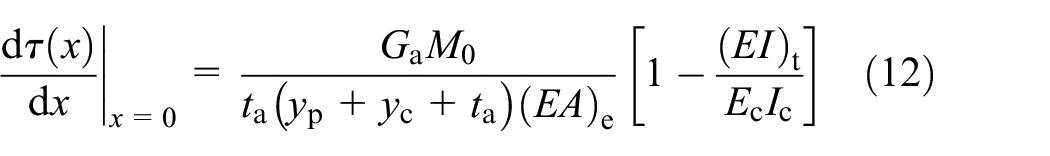
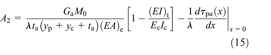
A 1 and A2 in equation (9) are constant coefficients determined from suitable boundary conditions. The first boundary condition is that the sectional curvature of both sides at the free laminate end should be kept continuous, which can be expressed as

M 0 in equation (11) is the total applied moment at the section of x = 0. Substituting equations (2) to (7) into equation (11) and ignoring the effects of shear deformations, the first boundary condition can be rewritten as
where
The second boundary condition is that the shear deformation of the adhesive layer at the point of zero interfacial shear stress should meet the following deformation compatibility
where Ls is the distance from the point of zero interfacial shear stress to the free laminate end. For FRP-strengthened cantilever members, the value of Ls is approximately equal to the FRP bond length Lp in Figure 1.
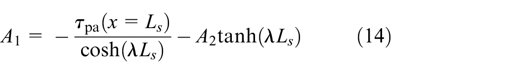
The coefficients A1 and A2 in equation (9) can therefore be determined by equations (12) and (13)
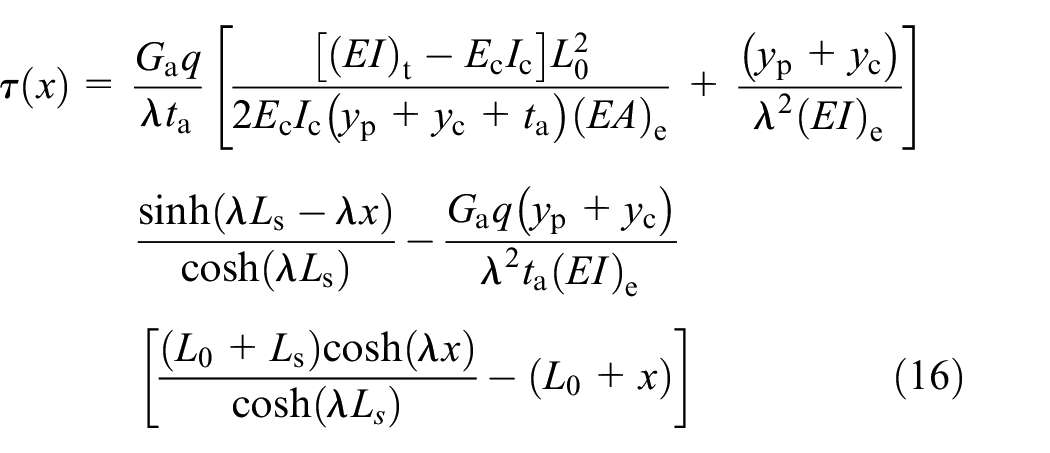
When an FRP-strengthened cantilever member is subjected to a UDL q, there exists a moment and interfacial shear stress of
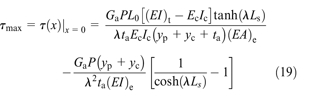
Consequently, the maximum interfacial shear stress occurs at the section of x = 0, and the value is
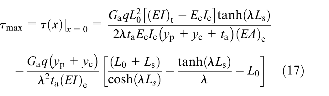
where L0 is the distance from the overhanging end to the free laminate end of the cantilever member.
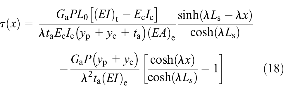
When the member is subjected to an SCL P at the overhanging end of the cantilever member, there exist a moment and interfacial shear stress of
Longitudinal strains in FRP laminates
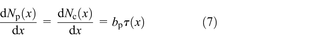
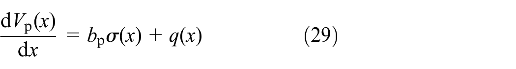
As shown in Figure 2, the longitudinal tension in FRP at any section of x, Np(x), can be determined from the combination of the boundary condition of Np(0) = 0 and either equations (7) and (16) or equations (7) and (18).
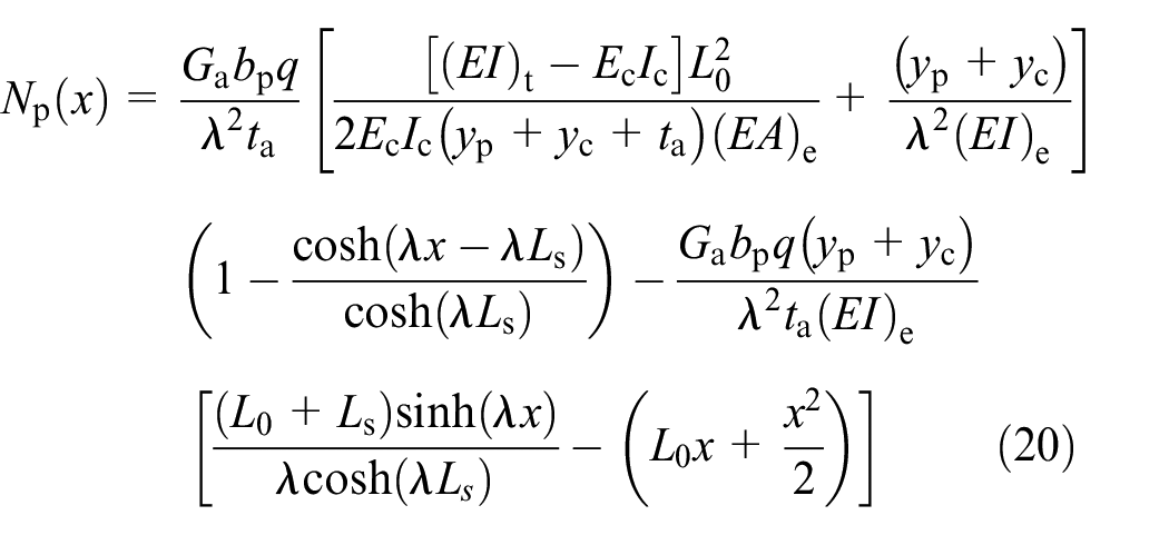
Under a UDL, q, the longitudinal tension in the FRP can be expressed as follows
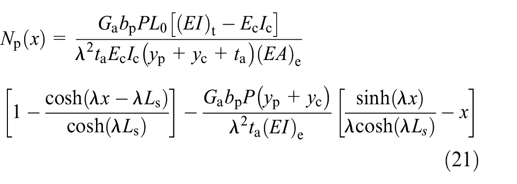
Under an SCL, P at the overhanging end of the cantilever member, the longitudinal tension in the FRP can be expressed as follows
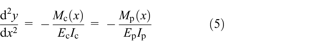
Neglecting the effects of shear deformations in both the cantilever member and FRP laminates, the bending moment in the FRP at any section of x can be determined from equations (5) and (6)
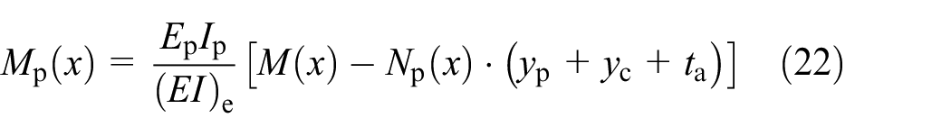
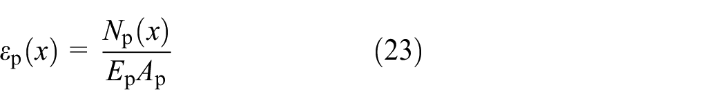
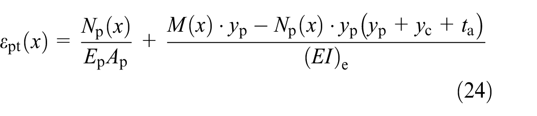
Thus, the axial strain εp(x) in the FRP and the longitudinal strain εpt(x) at the tops of the FRP laminates in the FRP-strengthened cantilever member are expressed as
Interfacial normal stresses
When the FRP-strengthened cantilever member is loaded, a vertical displacement exists between the laminate and the concrete member, which induces an interfacial normal stress in the adhesive layer. The interfacial normal stress denoted by σ(x) can be determined from the following expression
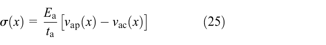
where Ea is the elastic modulus of the adhesive layer, and vap(x) and vac(x) are the vertical displacements at the bottoms of the FRP laminates and the top of the RC cantilever member, respectively.
Neglecting second-order terms, the following relationships can be obtained from the theory of material mechanics and the equilibrium of the infinitesimal elements of the FRP and cantilever members (Figure 2)
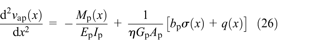


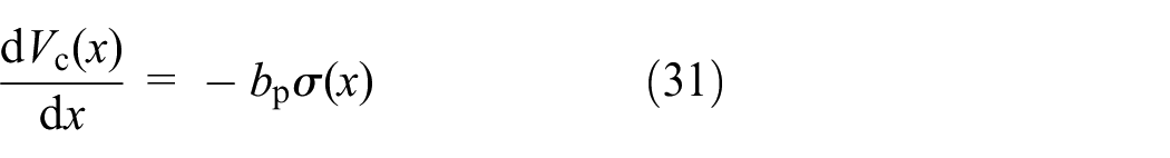
Thus, the vertical displacements, vap(x) and vac(x) in equation (26), can be expressed in terms of the interfacial shear and normal stresses. The governing differential equation for the interfacial normal stress in an FRP-strengthened cantilever structure can therefore be expressed as
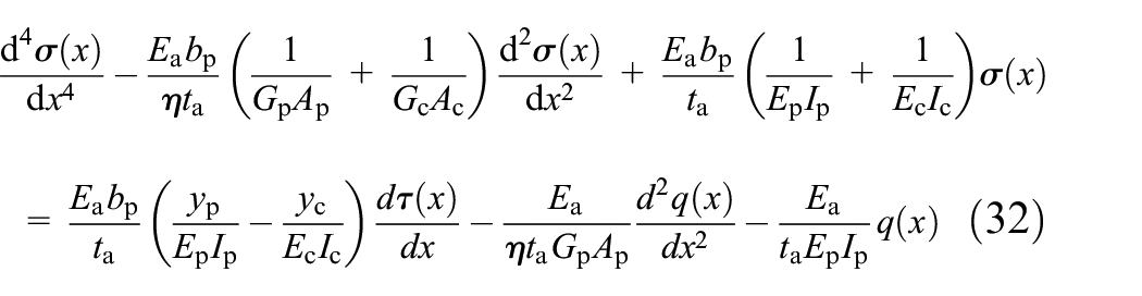
Neglecting the effects of shear deformations in both the FRP and cantilever member (Smith and Teng, 2001), the governing differential equation for the interfacial normal stress is simplified as

where
For an FRP-strengthened cantilever member under an arbitrary linear distributed load, the general solution for the interfacial normal stress is given by the following expression
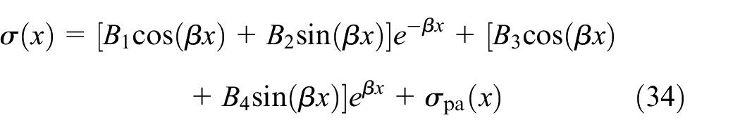
where
It is assumed that the interfacial normal stress approaches zero for large values of x and, as a result, B3 = B4 = 0. The coefficients B1 and B2 in equation (34) can be determined by the zero bending moment and zero shear force boundary conditions in the FRP laminates at x = 0, that is Mp(0) = 0 and Vp(0) = 0. The following boundary conditions can be determined by differentiating equation (25) two and three times and substituting equations (26) to equation (31) into the resulting expressions
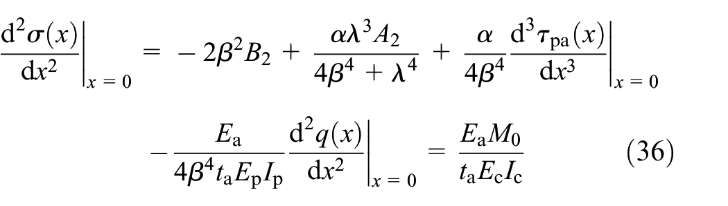
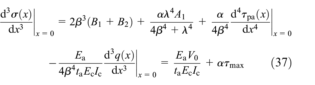
where M0, V0 and τmax are the total bending moment, total shear force and interfacial shear stress, respectively, at x = 0 in the FRP-strengthened cantilever member.
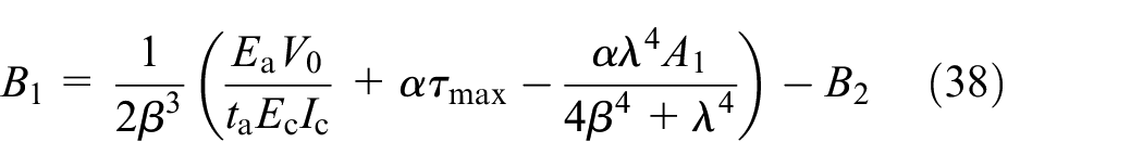
When the member is subjected to a UDL or an SCL at the overhanging end, the coefficients B1 and B2 in equation (34) can be determined by the following expressions
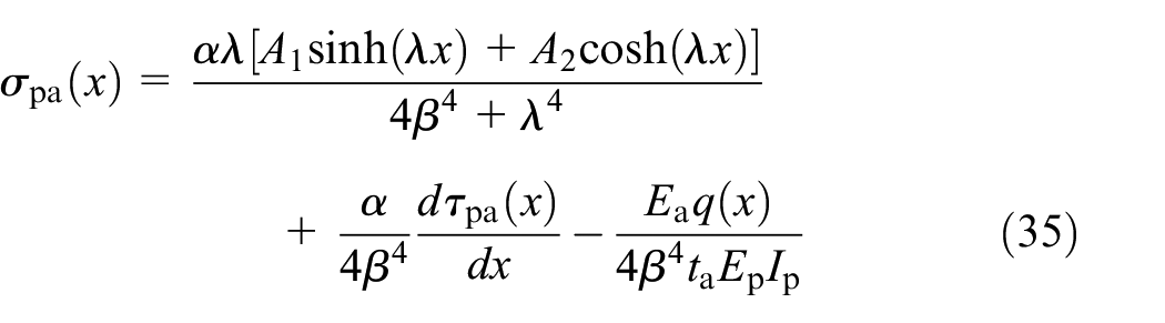
Thus, the interfacial normal stress at any section and, consequently, its maximum value in the FRP-strengthened cantilever member can be expressed as follows.
Under a UDL, q, the interfacial normal stress at any section and its maximum value in the FRP-strengthened cantilever member are
Under an SCL, P at the overhanging end of the cantilever member, the interfacial normal stress at any section and its maximum value in the FRP-strengthened cantilever member are
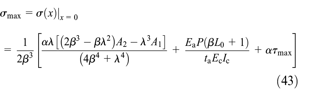
where the maximum interfacial shear stress τmax in the FRP-strengthened RC cantilever member should be calculated by equation (17) under a UDL or by equation (19) under an SCL at the overhanging end of the cantilever member.
Experimental verification of the theoretical results
To verify the proposed model, previous test results (Wan, 2016) from our group on cantilever slabs strengthened by CFRP sheets were used. In the test, two cantilever slabs (CS1-3V and CS1-5V) with the same dimensions and cantilever distances were prepared, as shown in Figure 3. The reinforcement and FRP ratios of the RC slab were 0.5% and 0.07%, respectively, which was designed based on a China Standard (GB 50367, 2013). The CFRP sheets were bonded on the slab with epoxy resin while a mechanical anchorage was applied on the fixed end of the cantilever slab. To understand the interfacial stress development with respect to loading, strain gauges were attached on the surfaces of the CFRP sheets along the longitudinal middle line. The material information of the cantilever member is summarized in Table 1.
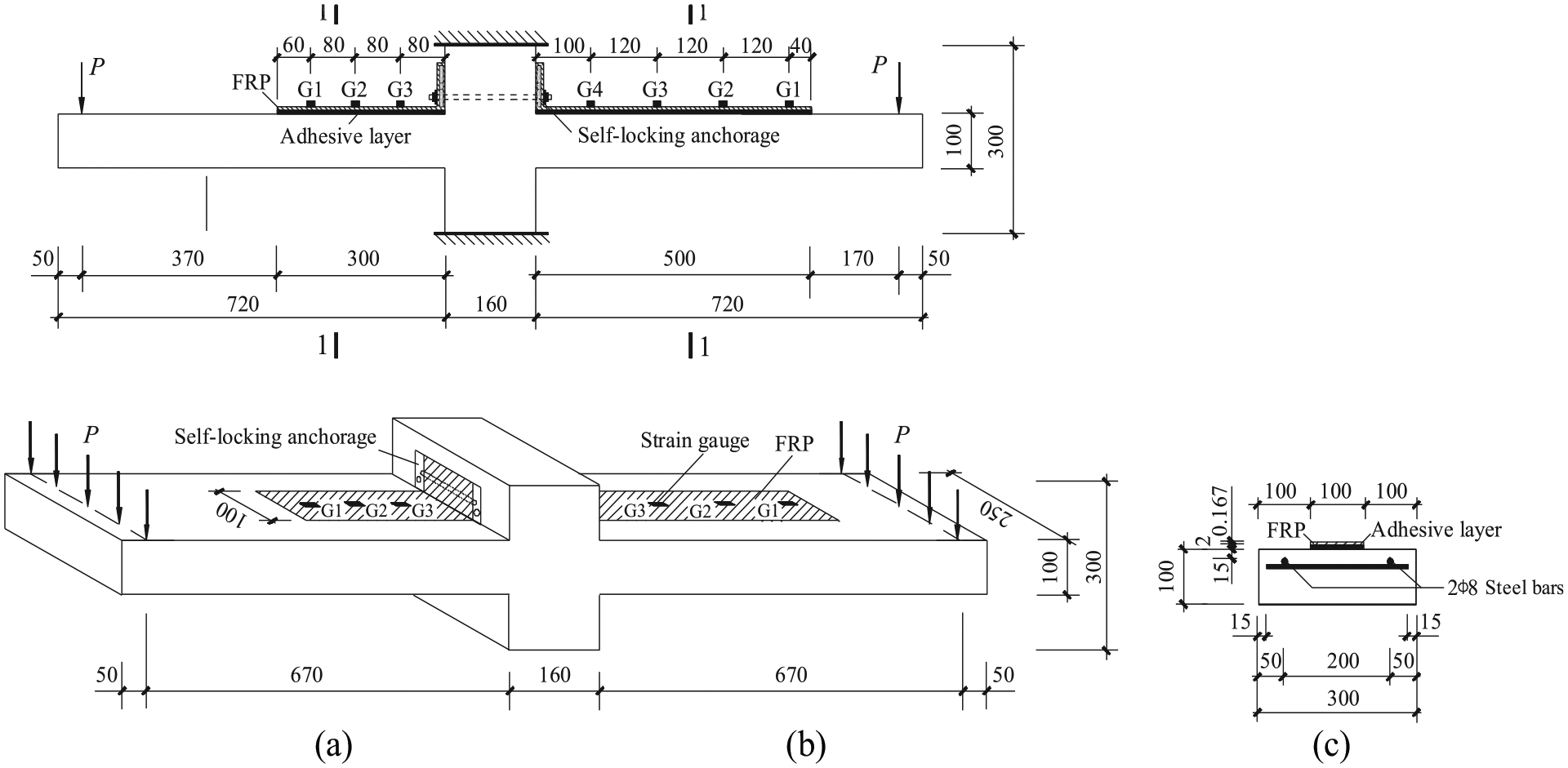
Strain gauge arrangement for specimens CS1-3V and CS1-5V (unit: mm): (a) CS1-3V, (b) CS1-5V and (c) Section 1-1.
Summarized material parameters of the test.
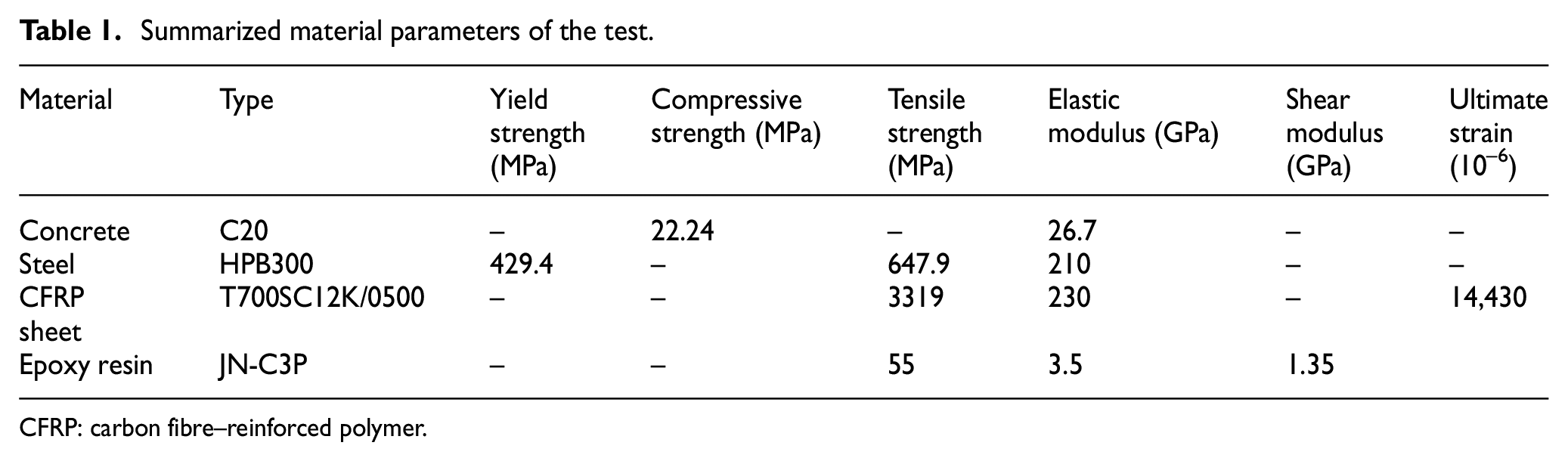
CFRP: carbon fibre–reinforced polymer.
During loading, the strains on the CFRP sheet were obtained. The strain results from G1 and G2 were selected for model verification. As shown in Figure 4, the calculated and experimental load–strain relationships were compared before the local debonding initiation occurred. For specimen CS1-3V, before debonding initiated at G2, the ratio of calculated and experimental strain values at G1 and G2 were 1.037 ± 0.08 and 0.989 ± 0.063, respectively. While for specimen CS1-5V, the ratio of calculated and experimental strain values at G1 and G2 were 1.011 ± 0.081 and 0.997 ± 0.057, respectively. The calculated results have a satisfactory agreement with the experimental results, which verified the reliability of the proposed model.
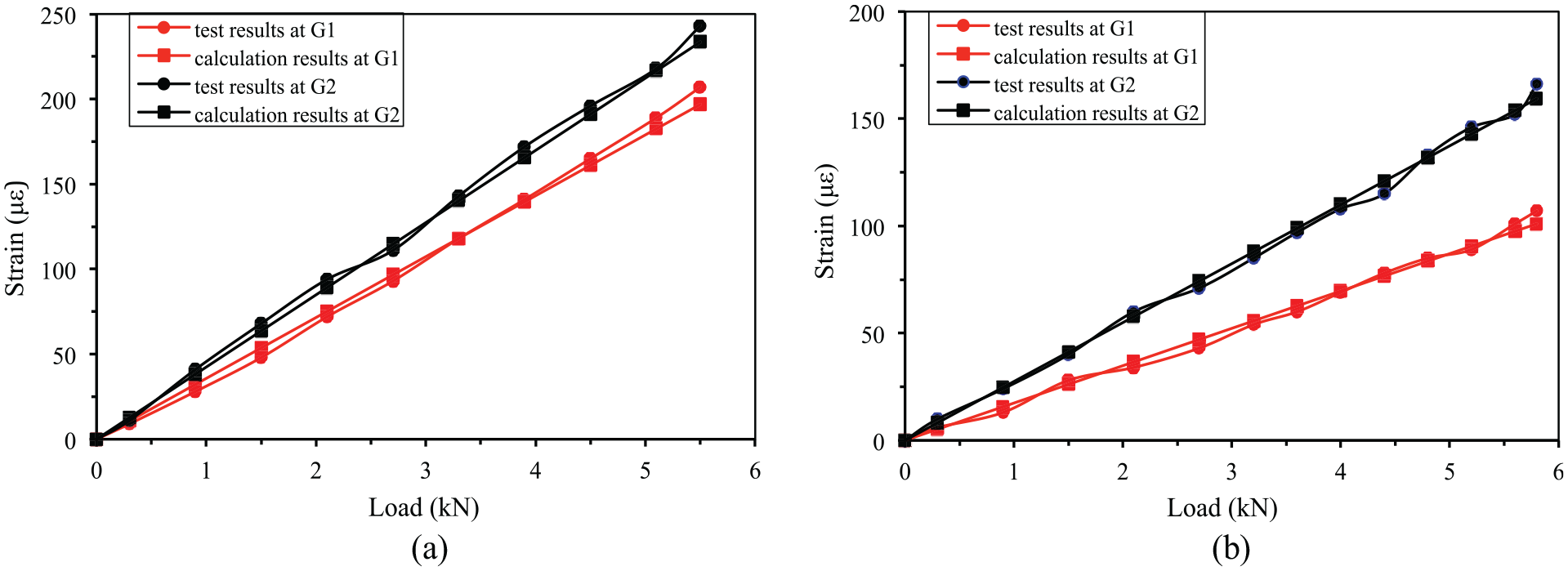
Comparison of the experimental and calculated load–strain results in the CFRPs before the local debonding: (a) CS1-3V and (b) CS1-5V.
Interfacial stress distribution for a typical cantilever member
As shown in Figure 1, externally bonded FRP-strengthened RC cantilever members subjected to either a UDL or an SCL at the overhanging end are further studied to understand the interfacial stress distributions. The widths and heights of RC cantilever members, which have rectangular cross-sections, are bc = 200 mm and hc = 300 mm, respectively. Both specimens have cantilever lengths of L = 1500 mm and employ three deformed bars with 16 mm diameters and two plain bars with 10 mm diameters as the tension and erection reinforcement, respectively. In addition, plain bar stirrups with 6.5 mm diameters that are spaced at 100 mm are placed along the entire longitudinal direction of the specimen. The widths and thicknesses of the FRP laminates are bp = 100 mm and tp = 2 mm, respectively. The FRP laminates are reliably anchored at the fixed end of the cantilever member but they are only pasted to the members near the free end and the bond length Lp =1000 mm (i.e. L0 in Figure 1 is equal to 500 mm). The thickness and shear modulus of the adhesive layer are ta = 2 mm and Ga = 2.6 GPa, and the elastic moduli of the concrete, FRP and adhesive layer are Ec = 30 GPa, Ep = 230 GPa and Ea = 6.7 GPa, respectively. The UDL is q = 30 kN/m, and the SCL at the overhanging end is P = 22.5 kN, which results in the same bending moments at the fixed ends of the FRP-strengthened cantilever members. The distributions of the interfacial shear and normal stresses near the free laminate end under either a UDL or an SCL at the overhanging end of the cantilever member are plotted in Figure 5.
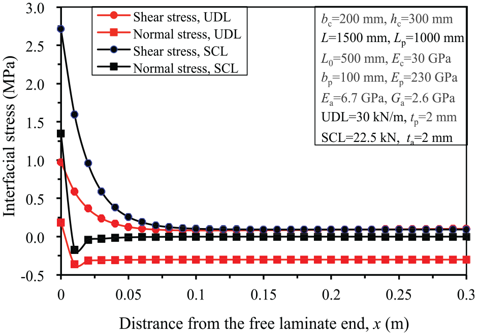
Interfacial stress distributions in FRP-strengthened cantilever members subjected to either a UDL or an SCL at the overhanging end.
The results in Figure 5 are obtained by solving the closed-form solutions. As shown, whether the cantilever member is subjected to either a UDL or an SCL at the overhanging end (they develop the same bending moments at the fixed end), obvious stress concentrations appear near the free laminate end due to the high interfacial stresses induced by discontinuities in the FRP. The maximum values of interfacial shear and normal stresses occur at the free laminate end, namely, the section of x = 0, and these values are several times higher than the mean values. Once the principal stress caused by the combined action of these maximum interfacial stresses exceeds the tensile strength of the concrete, an end-debonding failure will occur and prevent the full utilization of the tensile strength of the FRP. The interfacial shear and normal stresses drop rapidly to small values at a very short distance from the free laminate end. This short distance is approximately 0.2 times the cross-sectional height for the interfacial shear stress and 0.1 times the cross-sectional height for the normal stress. Then, the interfacial shear stresses in both loading cases remain nearly constant value, whereas the interfacial normal stress is reduced to zero under an SCL at the overhanging end and negative under a UDL.
Parametric analyses and discussions
In this section, the effects of various strengthening parameters on the maximum interfacial shear and normal stresses at the free laminate ends of the FRP-strengthened cantilever members under either a UDL or an SCL at the overhanging end are investigated. The results are important to engineers seeking to optimize the strengthening design parameters of these types of cantilever structures.
Effects of the FRP laminate thickness
The FRP laminate thickness is an important variable in strengthening design practice. Figure 6 shows the effects of FRP laminate thickness on the maximum interfacial shear and normal stresses at the free laminate ends of FRP-strengthened cantilever members. In this study, eight FRP laminate thicknesses are discussed: 0.111, 0.333, 0.5, 1, 2, 3, 4 and 6 mm.
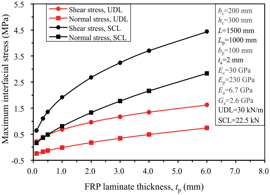
Effects of the FRP laminate thickness on the maximum interfacial stresses in FRP-strengthened cantilever members under either a UDL or an SCL at the overhanging end.
The results reveal that the laminate thickness has a considerable influence on the distributions and concentrations of interfacial stresses in FRP-strengthened cantilever members. As shown in Figure 6, whether the cantilever members are under a UDL or an SCL at the overhanging end, the maximum values of both interfacial shear and normal stresses increase significantly with increasing laminate thickness. Compared to the cantilever members subjected to UDLs, the interfacial shear and normal stresses in the cantilever members subjected to SCLs are obviously greater. Thus, increasing the laminate thickness (especially under an SCL at the overhanging end) can not only improve the flexural load-carrying capacity but also increase the maximum values of interfacial stresses and the stress concentrations. It is worth pointing out that the maximum value of interfacial normal stress under a UDL is negative (i.e. a compressive stress) when the laminate thickness is less than 1 mm and then turns to positive (i.e. a tensile stress) as the thickness increases, which is a different trend than that exhibited by simply supported members. Because the vertical uniform load acting on the laminates is opposite to the bending direction of the member, the vertical uniform load will counteract part of the interfacial tensile stresses in FRP-strengthened cantilever members and lead to either smaller or negative interfacial normal stresses. Therefore, after the incorporated amount of FRP has met the design requirements, arbitrarily increasing the laminate thickness to improve the structural design safety is unreasonable. The degree of interfacial stress concentration and the possibility of FRP end-debonding failure will increase greatly by subsequently increasing the FRP laminate thickness.
Effects of the FRP bond length
Figure 7 shows the influences of FRP bond length on the maximum shear and normal stresses. Seven sets of FRP bond lengths Lp, 700, 800, 900, 1000, 1100, 1200 and 1300 mm, are investigated, which correspond to relative ratios of FRP bond length to cantilever length, Lp/L, are 0.467, 0.533, 0.6, 0.667, 0.733, 0.8 and 0.867, respectively.
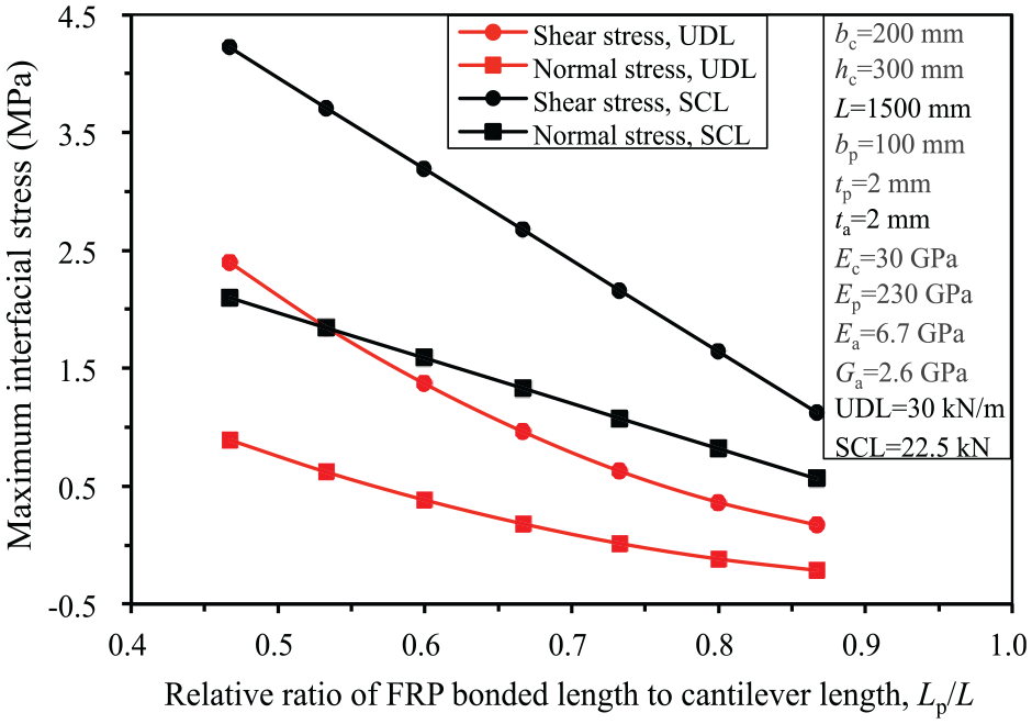
Effects of the FRP bond length on the maximum interfacial stresses in FRP-strengthened cantilever members under either a UDL or an SCL at the overhanging end.
As presented in Figure 7, it can be concluded that increasing the FRP bond length will approximately linearly decrease the maximum values of both interfacial shear and normal stresses under either a UDL or an SCL at the overhanging end. In particular, when the relative ratio of FRP bond length is greater than 0.75, the maximum value of the interfacial normal stress at the free laminate end becomes negative (i.e. a compressive stress) under a UDL. Therefore, increasing the FRP bond length significantly reduces the degree of interfacial stress concentration and the possibility of FRP end-debonding failure. However, existing experimental studies have shown that extending the purely pasted FRP to the free end of an FRP-strengthened member may still not completely prevent end-debonding failures because of the excessive deflection at the zero-moment overhanging end (Akbarzadeh and Maghsoudi, 2010; Zheng et al., 2012). In addition, extending the FRP to the free end will waste materials because the flexural moments (especially under UDLs) decrease rapidly with the distance to the fixed support. With regard to both safety and cost, it is suggested to select an appropriate FRP bond length and use simple mechanical anchors in the vicinity of the free laminate end of the cantilever member.
Effects of the adhesive layer thickness
The effects of the adhesive layer thickness on the maximum shear and normal stresses in the FRP-strengthened cantilever member are shown in Figure 8, wherein the thickness of the adhesive layer is varied from 0.2 to 6 mm.
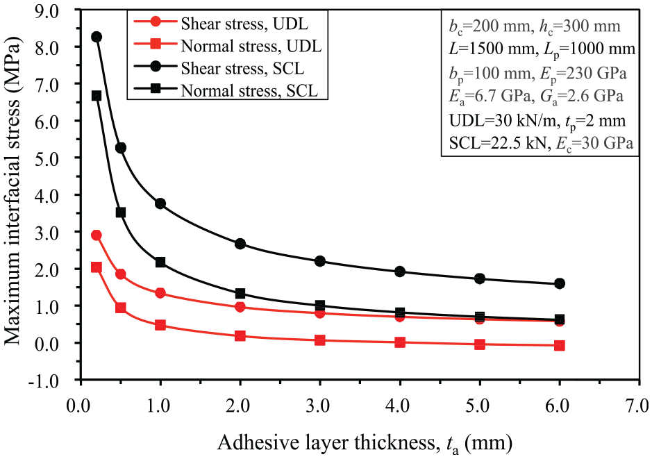
Effects of the adhesive layer thickness on the maximum interfacial stresses in FRP-strengthened cantilever members under either a UDL or an SCL at the overhanging end.
The comparative results show that the maximum values of the interfacial stresses and the degree of stress concentration at the free laminate end are considerably affected by the adhesive layer thickness. When the adhesive layer thickness is less than 1 mm, the maximum values of the interfacial shear and normal stresses decrease sharply with the increase in adhesive layer thickness, whether under a UDL or an SCL at the overhanging end. Then, the stress decreasing rates are slowed after the adhesive layer thickness exceeds 1 mm. Eventually, the maximum interfacial stresses approach small values as the adhesive layer thickness continuously increases. It seems reasonable that using a thicker adhesive layer (particularly in the vicinity of the edge) can reduce the level of stress concentration and the risk of FRP debonding at the free laminate end. However, excessive adhesive layer thickness is bound to cause larger shrinkage deformation in the curing process, which results in poor bonding and potentially premature debonding between the FRP and concrete (He and Zhou, 2005; Smith and Teng, 2001). Thus, the thickness should be taken into consideration by the designer to avoid using adhesive layers that are either too thin or too thick. In practical applications, adhesive layer thicknesses of 1–2 mm are usually recommended on the premise of the in situ FRP laminates being fully impregnated with the adhesive (He and Zhou, 2005; Yao and Teng, 2007).
Effects of the elastic moduli of FRP laminates
To discuss the effects of the FRP elastic modulus on the maximum interfacial shear and normal stresses at the free laminate end, four kinds of laminates, including aramid fibre-reinforced polymer (AFRP), basalt fibre-reinforced polymer (BFRP), and glass fibre-reinforced polymer (GFRP) with elasticity moduli of 230, 120, 90 and 50 GPa, respectively, were investigated. The comparative analysis results are shown in Figure 9.
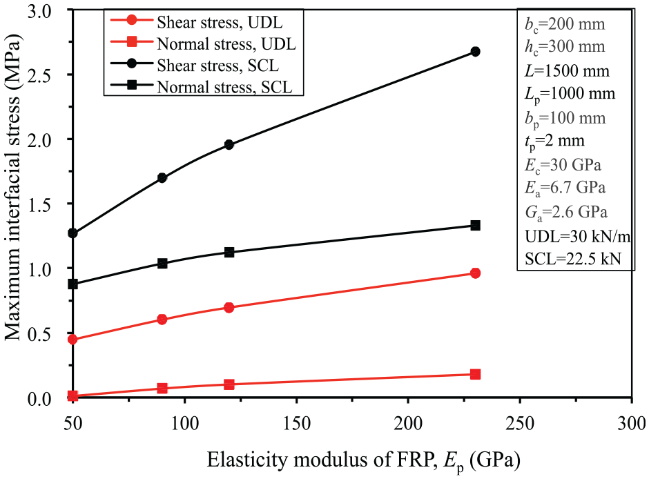
Effects of the FRP elastic modulus on the maximum interfacial stresses in FRP-strengthened cantilever members under either a UDL or an SCL at the overhanging end.
As the results show, whether the strengthened member is subjected to a UDL or an SCL at the overhanging end, the maximum values of the interfacial shear and normal stresses at the free laminate end are almost linearly reduced with increases in the elastic modulus of the FRP. The less rigid the laminate (the laminates from highest to lowest elastic modulus are CFRP, AFRP, BFRP and GFRP) is, the smaller the tensile force developed in laminates and the smaller the corresponding interfacial stresses under the same load. Therefore, FRP laminates with relatively low elastic moduli can effectively reduce the level of interfacial stress concentration and the possibility of end-debonding failure. However, if the corresponding tensile strengths of such laminates are small, the expected flexural capacity enhancements may not be achieved. To effectively prevent premature delamination and achieve the expected strengthening effect and low cost, FRP laminates with high tensile strengths and low elastic moduli are suggested for practical engineering applications.
Conclusion
In this article, theoretical analysis was conducted to investigate the interfacial stresses in RC cantilever members externally bonded with FRP laminates. From the results and discussion, the following conclusions can be drawn.
According to the deformation compatibility and static equilibrium conditions, a linear elastic analytical model is developed under an arbitrary linear distributed load, and closed-form expressions under either a UDL or an SCL at the overhanging end are proposed. The good agreement between the calculated and existing test results verified the reliability of the proposed model. The given expressions are simple and suitable for manually calculating the interfacial stresses and the longitudinal strain in FRP laminates of flexural FRP-strengthened cantilever members before the local debonding initiation occurred.
On the premise of the laminates being reliably anchored at the fixed end, an obvious stress concentration appears near the free laminate end in both loading cases, which may cause brittle end-debonding failure. The interfacial stresses drop quickly to small values at a very short distance from the free laminate end. Then, the interfacial shear stresses remain constant, whereas the normal stress is reduced to zero under an SCL at the overhanging end and negative under a UDL.
The distributions of interfacial stresses and the stress concentrations in FRP-strengthened RC cantilever members are influenced by various parameters. Under the same conditions, the maximum interfacial stresses and the risk of free laminate end-debonding can be decreased to varying degrees by reducing the FRP thickness, increasing FRP bonding length and increasing adhesive layer thickness, and by using less rigid laminates with high tensile strength. These results are useful for engineers seeking to optimize strengthening design parameters and implement reliable debonding prevention measures.
Footnotes
Declaration of Conflicting Interests
The author(s) declared no potential conflicts of interest with respect to the research, authorship and/or publication of this article.
Funding
The author(s) disclosed receipt of the following financial support for the research, authorship and/or publication of this article: This work was supported by the National Natural Science Foundation of China through Grants 51878664, 51378507 and 51708133, the Key Program of Hunan Provincial Natural Science Foundation of China through Grant 2013JJ2005 and the Key Program of the Science and Technology Project of Hunan Province through Grant 2017SK2260.