
Abstract
To investigate the structural performance of Tou–Kung, two 1/3.52-scaled models of Tou–Kung were designed and tested subjected to vertical loading and quasi-static loading. Also, the finite element models of intact Tou–Kung and tilting Tou–Kung were established. Based on the validation of experimental results and finite element models, numerical simulation analysis of the models was carried out to study the influence of tilting angle on the behaviors of Tou–Kung. It is shown that the failure modes of the models were the compressive fracture of Da-Tou under vertical load, the shear failure of the dowel at Da-Tou, and the slipping between Da-Tou and Pingban-Fang subjected to lateral cyclic loads. The relationship of vertical load and vertical displacement was obtained and analyzed, and the vertical initial stiffness and bearing capacity of the models descended with the increase in tilting angle. The hysteretic loops of the tilting models subjected to cyclic loads are asymmetrical in positive and negative loading, and the asymmetrical degrees of the curves are much significant with a larger tilting angle of the models. With the increase in tilting angle, the lateral stiffness and ultimate load increased in positive loading, and both of them decreased in negative loading due to the tilting of the models. Also, the equivalent viscous damping coefficient of the models decreases with a larger tilting angle of Tou–Kung.
Keywords
Introduction
Chinese historic timber structures have been well known for their unique structural style and extraordinary artistic expression. They have a profound influence on the development of architectural style in East Asia, especially in Japan and South Korea (Li et al., 2015; Qi et al., 2017; Wu et al., 2018). A large number of palaces, pavilions, and temples have been constructed in history, but only a few have been well survived after natural disasters and human wars for thousands of years (Zhang et al., 2011). The existing timber structures have become an invaluable asset of the owning countries (Crayssac et al., 2018) and an important witness of world civilization. To preserve them as long as possible, it is imperative to study their structural behaviors for the safety assessment and the protection of the timber structures (Zhao et al., 2011).
Chinese historic timber structures mainly consist of four layers from bottom to top, including platform, column-beam frame, Tou–Kung, and roof (Liang, 1984), as shown in Figure 1. Columns are directly laid on the plinth embedded in the platform. The column-beam frame is composed of columns and beams connected by mortise–tenon connections. The roof is made up of transverse beam frames and coverings. The Tou–Kung layer lies between the column-beam frame and the roof, and it is assembled together in crisscross pattern by Tous and Kungs. Tou refers to a chunk of timber and connects a bow-shaped arm (called Kung) by a small dowel (Fang et al., 2001).
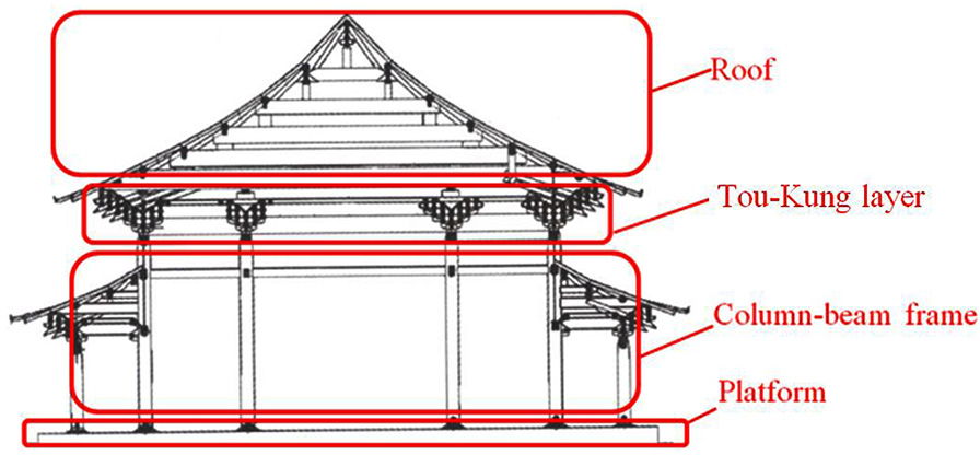
Historic timber structure.
Tou–Kung is one of the most principal characteristics and unique component of Chinese historic structures. It first appeared in Shang dynasty 3000 years ago. The configuration of Tou–Kung has a significant development and is gradually determined with time. It is complicated in structure and beautiful in appearance. Tou-Kung sets carries both vertical loads from the roof and horizontal loads caused by earthquake action or wind (Meng et al., 2018). It can resist the partial lateral loads by the friction force between Tou and Kung and directly transfer the vertical loads to column by Pingban-Fang or the column head. It is complex to analyze the force mechanism and evaluate the seismic performance of Tou–Kung. Tou–Kung has an architectural decoration role and structural functions such as transfer loads and energy dissipation, which has an important influence on the mechanical properties and seismic behaviors of the overall structure.
Many investigations on the performance of Tou–Kung have been carried out based on the tests and the finite element analysis (FEA; Sun, 2009; Yuan et al., 2011; Zhang et al., 2003; Zhu et al., 2010). D’Ayala and Tsai (2008) investigated the performance of Dieh-Dou set subjected to monotonic loads. The results showed that the rotation stiffness of the set was determined by the vertical loads exerted to the set, but the lateral stiffness was basically independent of the loads. Kitamori et al. (2010) performed a research on the seismic performance of Tou–Kung set in Japanese historic timber structures subjected to the lateral loads. The mechanical model of a Tou between Kungs was proposed based on the rotation of the block, and the moment formula of the block was predicted considering the influence of axial loads. It is shown that the predictions coincided well with the experimental data. Chen et al. (2014) conducted an experiment study on the behaviors of two typical Tou–Kung sets in Yingxian Wood Pagoda subjected to vertical loads. The failure modes of the sets were obtained and classified, including compressive yield and tensile fracture of Tous perpendicular to grain and flexural breaking-off of Kungs perpendicular to grain. The behaviors of the sets were analyzed based on the experimental observations. The formulas of the initial stiffness and the vertical capacity of the sets were predicted by the similitude theory. Fujita et al. (2000) carried out the quasi-static load tests and the shaking table tests of bracket sets in Japanese historic timber structures to investigate the seismic performance of bracket sets. The lateral stiffness, natural frequency, and hysteretic curves were obtained, and the restoring force model of the sets was developed. Based on the model, the response analyses of the sets were simulated, and the analysis results showed a good agreement with the results of shaking table tests. Xie et al. (2015) performed an investigation on the seismic performance of Tou–Kung set in historic timber structures. The failure modes of the sets were the splitting-off of San-Dou and fork-column and the fracture and compressive yielding of Lu-Dou. The hysteretic curves, rotation stiffness, and energy dissipation capacity of the sets were obtained and analyzed. Then, the relationship formula between Tou-Kung rotational stiffness and vertical load is proposed.
Due to the disadvantages of flammability, shrinkage and swelling, and easy decay for wood, almost all the existing timber structures show varying levels of damage after going through long environmental erosion, such as pulling-out of the tenon in mortise–tenon connections, property degradation of aging wood, cracking along the longitudinal direction, and tilting of Tou–Kung sets (Figure 2). However, previous investigations mainly focus on the behaviors of intact Tou–-Kung in historic timber structures without tilting by experimental analysis and FEA. The research studies of Tou–Kung considering tilting have not been reported.
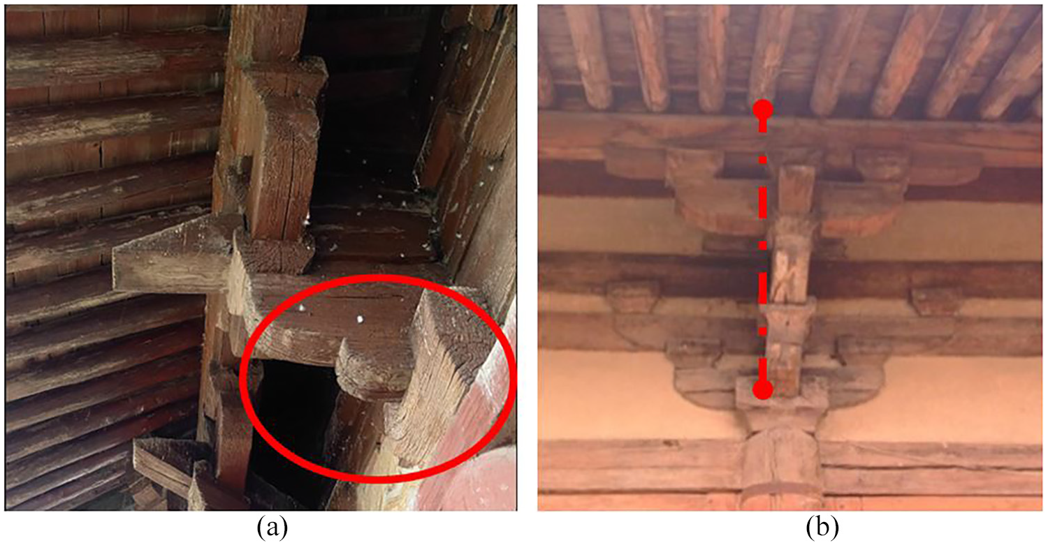
Damage of historic timber structure: (a) compressive cracking and (b) tilting of Tou–Kung sets.
Based on the tests of two intact Tou–Kung sets subjected to vertical loading and quasi-static loading, numerical simulation of four models, including one intact model and three tilting models, was carried out to investigate the influence of tilting angle of the models on the seismic performance of Tou–Kung.
Experimental program
Design of specimens
To investigate the structural behaviors of Tou–Kung in historic timber structures, two Tou–Kung sets were designed and constructed following the Construction Principle of Qing Dynasty, as shown in Figure 3. All members of the prototype Tou–Kung were fabricated by a dimension module of c = 17.6 mm specified by the Construction Principle of Qing Dynasty, and the scale of experimental models was determined to be 1/3.52. Two experimental models have the same details, and they were designated as TK-1 and TK-2, which were used for vertical loading test and quasi-static test, respectively. Configurations and dimensions of the members are shown in Figure 4 and Table 1. Pinus koraiensis was used for the experimental models, and its mechanical properties are shown in Table 2.
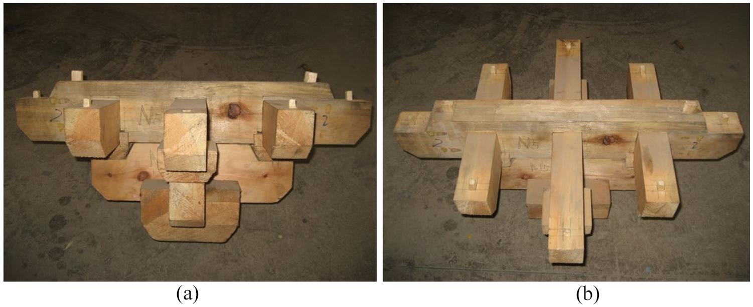
Test model: (a) side view and (b) top view.
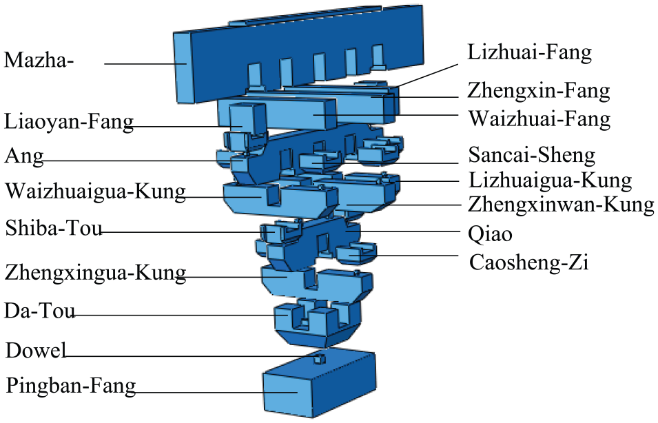
Configurations of the test models.
Dimensions of the test models.
Material properties of the wood.
E, G, and μ are elastic modulus, shear modulus, and Poisson’s ratio of the wood, respectively. The units of elastic modulus and shear modulus are MPa in the table. The subscripts 1, 2, and 3 are the longitudinal direction, the tangential direction, and the radial direction of the wood, respectively.
Loading scheme
TK-1
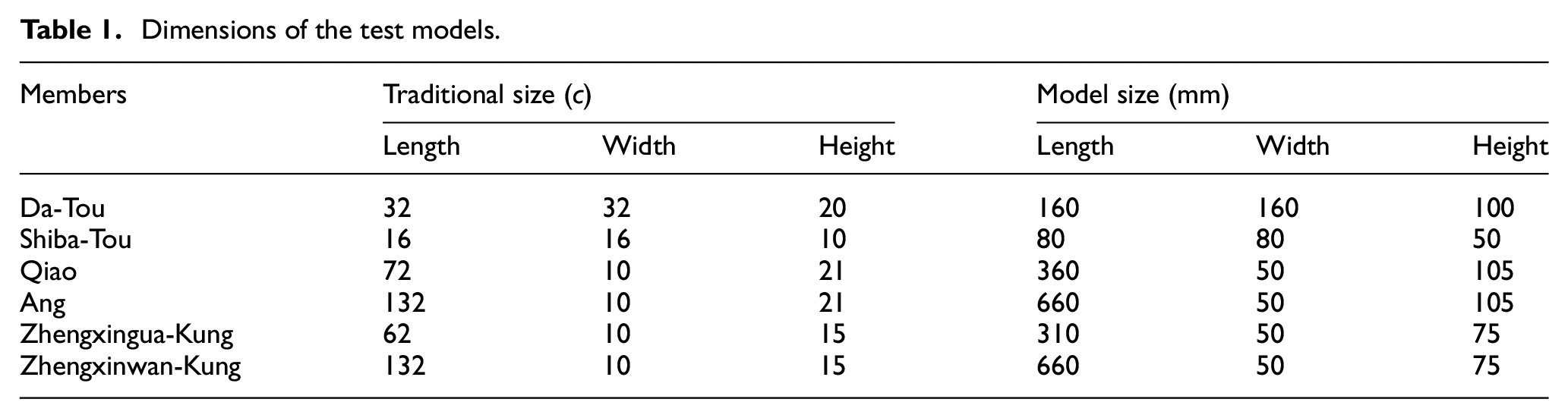
The force-controlled loading was used for the loading of TK-1. The monotonic vertical load P is applied to the top of TK-1 by a ±500 kN jack with an increase of 5 kN. Figure 5 shows the test setup of TK-1.
Test setup of TK-1.
TK-2
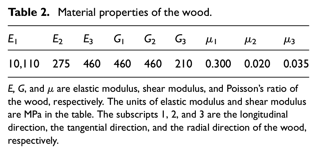
Figure 6 shows the basic configuration of a typical test setup for TK-2, which can exert a vertical axial load and lateral load or displacement on the specimens. The vertical axial load of 10 kN was exerted to the top of TK-2 by a ±500 kN capacity vertical jack. Then, lateral loads were applied at the end of the upper beam through horizontal jack, which had a force capacity of ±500 kN and a displacement capacity of ±250 mm. The vertical jack can freely move by three rollers between reaction beam and hydraulic jack with the deformation of the connections during the loading.
Test setup of TK-2.
Displacement-controlled loading was adopted for the loading of TK-2 following the Chinese Code for Specification for Seismic Test of Buildings (JGJ/T101-2015), as shown in Figure 7. At the initial phase of loading, the lateral loads were repeated once with an increase of 2 mm until the slip appeared between members in TK-2. Then, two cycles were applied at each displacement-controlled level with an increase of 5 mm.
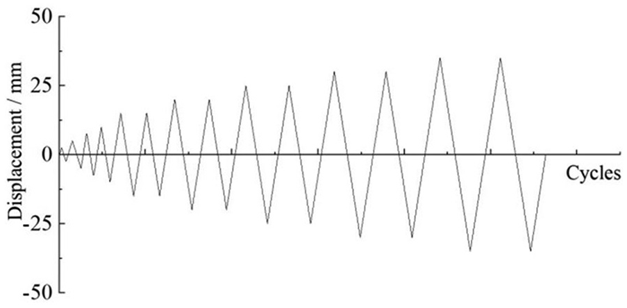
Loading history.
Failure modes
TK-1
At the initial stage of loading, the gap between members of TK-1 closed and the overall vertical stiffness of TK-1 increased with the increase in vertical loads. During the whole loading process, the vertical loads were mainly transferred along the central axis of Tous. With a larger P, the axial load of each Tou increased, and each Kung was mainly subjected to moment. There was an obvious overall vertical plastic deformation for TK-1. The failure modes of TK-1 were compressive fracturing of Da-Tou and compressive deformation of Qiao, as shown in Figure 8.
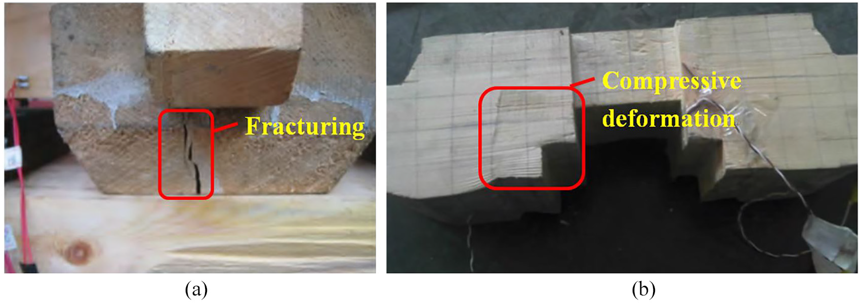
Failure modes of TK-1: (a) fracturing of Da-Tou and (b) deformation of Qiao.
TK-2
The overall lateral deformation of TK-2 increased with the increase in horizontal displacement, and the slipping occurred between Da-Tou and Pingban-Fang with a regular crackling sound. With a larger cyclic displacement, the slipping increased gradually, and dowel at the Da-Tou produced a large amount of shear deformation, as shown in Figure 9. Although the Tou–Kung set was not damaged, the larger slipping between Da-Tou and Pingban-Fang would lead to the collapse of the roof.
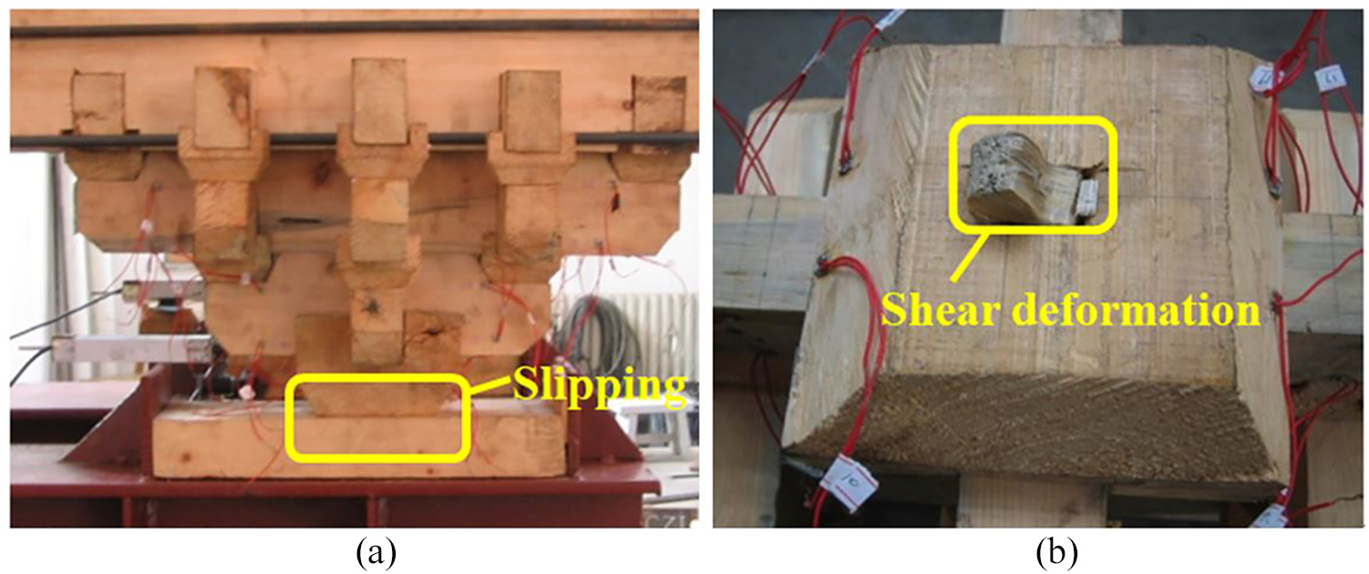
Failure modes of TK-2: (a) slipping between Da-Tou and Pingban-Fang and (b) shear deformation of dowel at the Da-Tou.
Finite element simulation
Constitutive relation
The stress–strain curves of wood consist of two stages, including elastic stage and plastic stage. The wood exhibits orthotropic properties in elastic stage, and the material properties are listed in Table 2. In the plastic stage, the elastoplastic analysis is used for the wood. In this article, the tension state or compression state along the longitudinal and perpendicular directions is mainly considered, and the constitutive relation along the longitudinal direction suggested by Chen (2003) is adopted, as shown in Figure 10(a). fce, fcu, and ftu are the compressive yield strength, compressive ultimate strength, and tensile ultimate strength along the longitudinal direction, respectively, and εce, εcu, and εtu are the corresponding compression or tensile strain, and E is the elastic modulus in the elastic stage. Also, the constitutive relation along the perpendicular direction adopts for linear strengthened elastoplastic model in compression and considers brittle fracture in tension, as shown in Figure 10(b). fce and ftu are the compressive yield strength and tensile ultimate strength along the perpendicular direction, respectively, and εce and εtu are the corresponding compression or tensile strain.
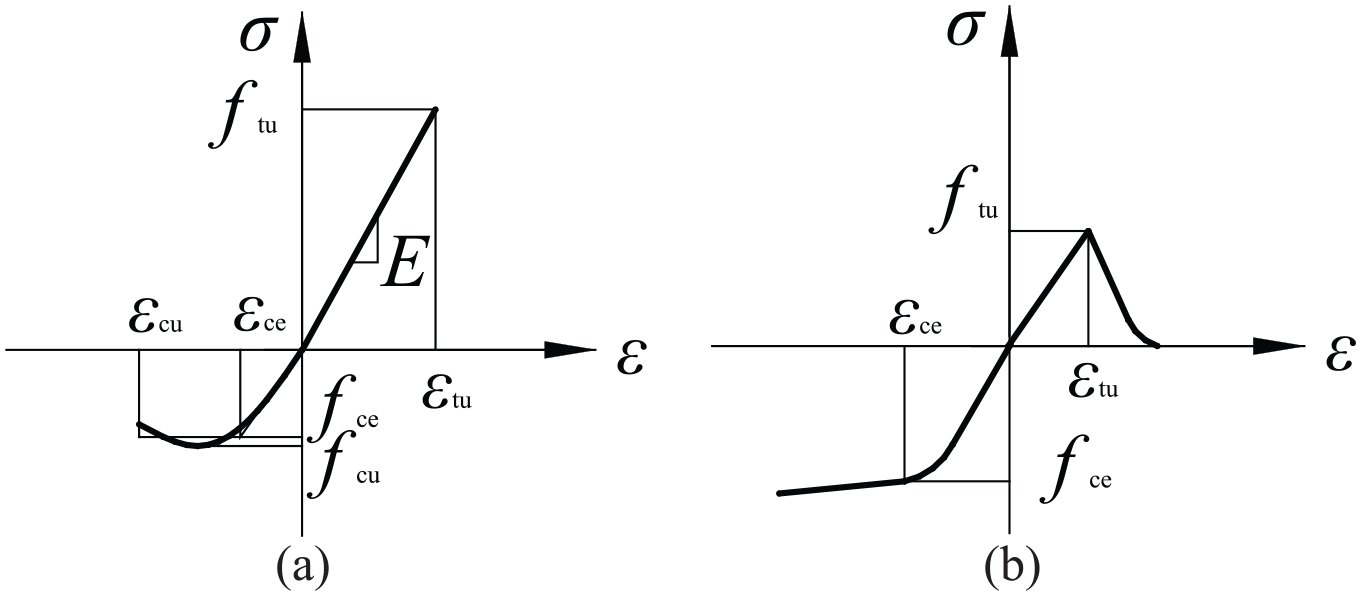
Constitutive relation of the model: (a) constitutive model along the longitudinal direction and (b) constitutive model along the perpendicular direction.
Interactions
When the surfaces of members contact, the tangential stress and the normal stress were transferred between the contact surfaces. The model of Coulomb friction is used to consider the relative slipping between the contact surfaces, where friction coefficient is adopted to represent the friction behavior between the surfaces. As shown in equation (1), when the tangential force F of the contact surfaces is less than the critical force Fc, there is no relative slipping between the contact surfaces under the constant compression N. Otherwise, a tangential relative slipping will occur at the contact surfaces. Based on the previous experiments conducted, the friction coefficient μs is taken as 0.45.

The normal behaviors between the contact surfaces are defined as “hard contact.” When the stress of contact surfaces is compression stress, the gap closed, and the contact constraint is applied. Otherwise, the contact surfaces are separated, and the constraint is removed. The contact stress is not transferred.
In ABAQUS, the algorithms for simulating the interaction of contact surfaces include general contact and contact pair. To simulate the loading process of Tou–Kung more accurately and truthfully, the general contact is adopted due to the automatically defining contact surfaces between all entities in the model.
Tilting angle of Tou–Kung
The integral tilting of Tou–Kung is realized by cutting Pingban-Fang at a certain angle θ. This article mainly simulates the tilting of Tou–Kung caused by the different embedded deformation of Pingban-Fang subjected to the local compression stress of Da-Tou, due to the orthotropic properties of wood and damage by worms. According to the theory of triangle embedded compression in large elastoplastic deformation of wood (Qin, 2012), the embedded compression zone can be divided into compression zone in the range of load (in the range of xp (yp)) and compression zone out of the range of load (in the range of x1 (y1 and y2)), as shown in Figure 11. The compressive deformation f(x) in the range of xp is a linear function about θ, that is, f(x) = θx. The compressive deformation in the range of x1 can be expressed as f(x) = θxpe–a1x, where a1 is equal to 1.5/z0. Likewise, the compressive deformation f(y) in the range of yp and y1 (y2) can be obtained as shown in Figure 11(b), where a2 is equal to 1.5n/z0, and n is taken as 5–7.
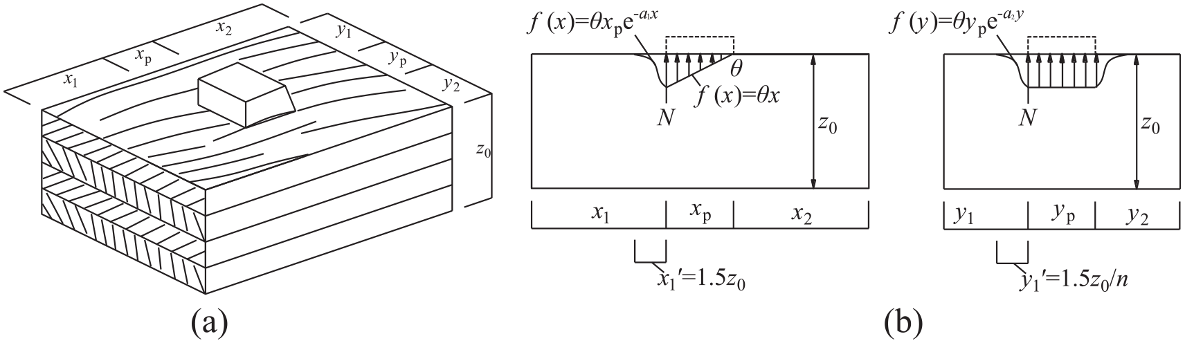
Sketch of triangle-embedded compression: (a) embedded compression and (b) deformation of embedded compressive zone.
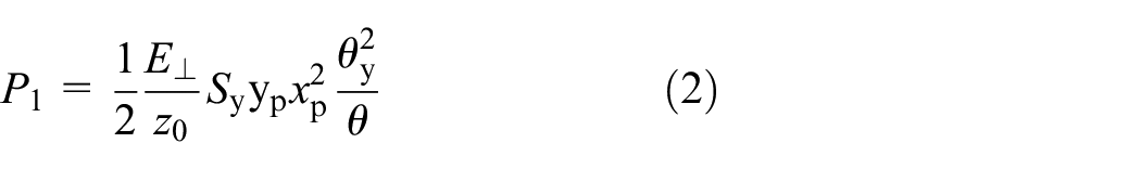
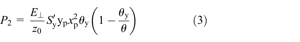
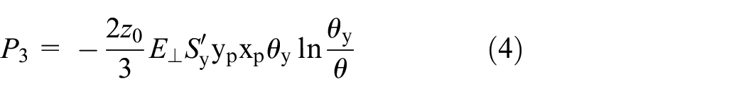
The bending moment caused by triangle-embedded compression in the plastic stage is divided into two parts in the range of xp (yp) and x1 (y1 and y2). The former is generated by the compressive counterforce P1 and P2 in the range of xp at the elastic and plastic stages, respectively. The latter is induced by the compressive counterforce P3 and P4 in the range of x1 at the elastic and plastic stages, respectively. The following equations can be obtained by mechanics of materials
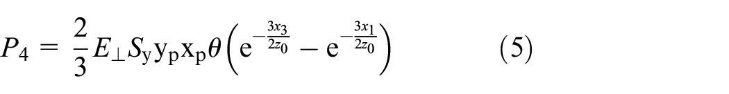
where
The following equation can be given by equilibrium condition of Pingban-Fang

From equations (2) to (6), the embedded angle θ of Pingban-Fang (tilting angle of Da-Tou) can be obtained, and θ is equal to 0.08 rad or about 5°. Thus, the angle θ of Pingban-Fang is taken as 0°, 2°, 4°, and 6°, corresponding to the finite element models (FEMs) FEM-1, FEM-2, FEM-3, and FEM-4, respectively.
Mesh and boundary conditions
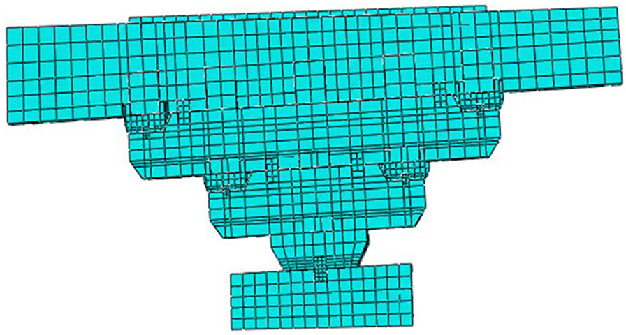
It is crucial to select the proper element and mesh for FEA. The hexahedron linear-reduced-integral solid element C3D8R improves the computational accuracy to displacement, and the accuracy cannot be greatly affected when the mesh is significantly distorted. Thus, the solid element C3D8R is used to mesh the model, as shown in Figure 12. The basic mesh size is 15 mm × 15 mm, and the size is relatively refined at the contact surfaces. Six degrees of freedom of the bottom surface of Pingban-Fang are restrained.
Mesh of the model.
Validation of FEM and experiment
Figure 13 shows the comparison of load P–displacement Δ curves of FEM and experimental results subjected to the vertical loads or cyclic loads. In Figure 13(a), P is the load of the jack on the top of Mazha-Tou, and Δ is the vertical displacement of Mazha-Tou. Δ is the lateral displacement at the end of Mazha-Tou, and P is the corresponding load in Figure 13(b). It can be seen from Figure 13 that there is an acceptable error between both the curves, and the initial stiffness and ultimate load of FEM are larger than those of experimental results. However, the curves of FEM coincide quite well with the experimental curves in general.
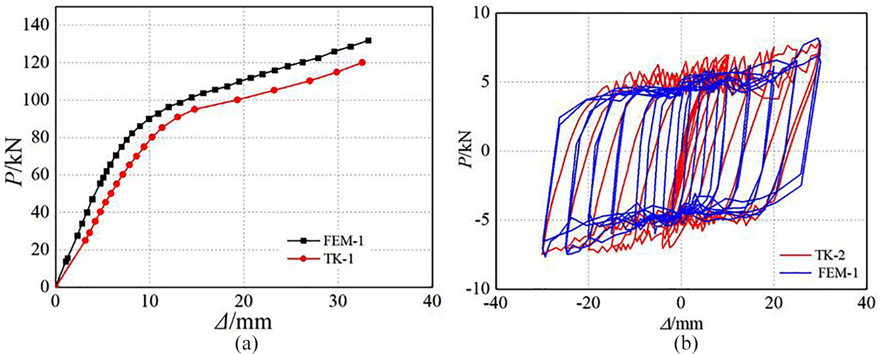
Comparison of FEM and experimental results: (a) vertical loading test and (b) quasi-static test.
Numerical simulation of tilting Tou–Kung under vertical load
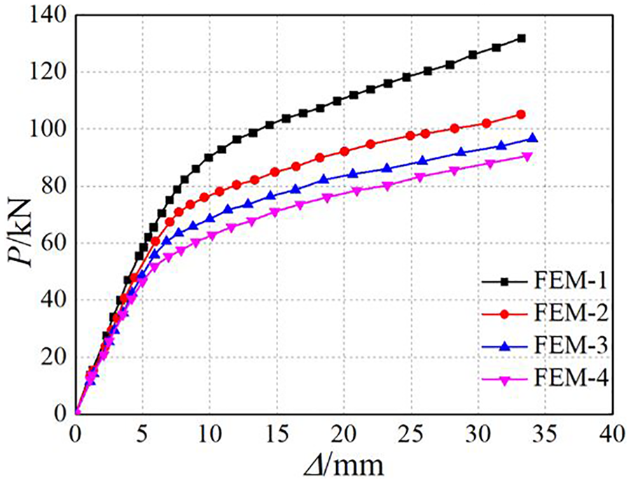
The FEAs of FEM-1, FEM-2, FEM-3, and FEM-4 subjected to vertical loads are carried out by controlling the loads. Figure 14 shows load P–displacement Δ curves of the models with different tilting angles, where P and Δ have the same meanings as Figure 13(a).
P–Δ curves of the models with different tilting angles.
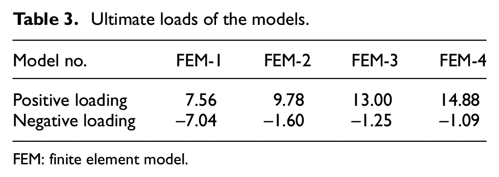
Bearing capacity of Tou–Kung
As shown in Figure 14, the curves can be divided into stable loading stage and instable loading stage. At the instable loading stage, the slope of the curves gradually decreases. Thus, the maximum load at the stable loading stage is defined as the allowable bearing capacity of Tou–Kung, which is similar to the allowable stress in Material Mechanics. With a larger tilting angle, the vertical deformation increases, and the stiffness decreases. Thus, the maximum load of FEM-4 at the loading stage is taken as the allowable bearing capacity of Tou–Kung considering the higher safety factor of Tou–Kung.
Based on the results of FEM, the maximum load and maximum displacement of FEM-4 at the stable loading stage are 58 kN and 7 mm, respectively. Correspondingly, the allowable bearing capacity of FEM-1, FEM-2, and FEM-3 is 82, 71, and 64 kN, respectively. It is obvious that the allowable bearing capacity of Tou–Kung decreases with a larger tilting angle, and the descending range is about 15%–30%, indicating that the tilting angle of Tou–Kung has a significant effect on its allowable bearing capacity.
Numerical simulation of tilting Tou–Kung under cyclic loads
To investigate the influence of tilting angle on the seismic performance of Tou–Kung, the numerical simulation of the models was carried out under cyclic loads, and the hysteretic curves, stiffness degradation, and capacity of energy dissipation were analyzed.
Hysteretic loops
The numerical simulation is carried out under cyclic loads by ABAQUS, where the positive is defined as the direction of resisting the tilting of Tou–Kung, and the negative is the direction of quickening the tilting of Tou–Kung. Figure 15 shows the hysteretic loops of lateral load P–displacement Δ of the models, where P and Δ have the same meaning as Figure 13(b).
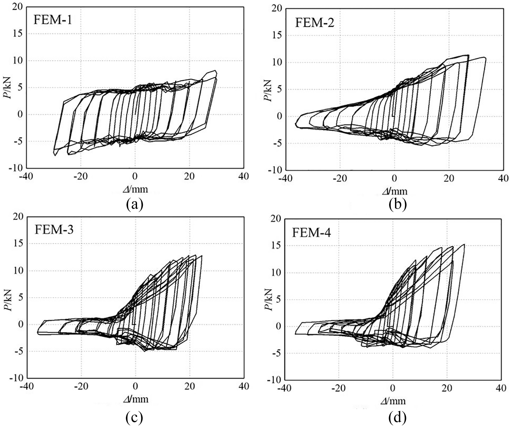
Hysteretic loops of the models: (a) FEM-1, (b) FEM-2, (c) FEM-3, and (d) FEM-4.
It can be seen from Figure 15 that the hysteretic loops of the intact models (FEM-1) is symmetry in positive and negative load. However, the loops of the tilting models (FEM-2, FEM-3, and FEM-4) are obviously asymmetry, and the degrees of asymmetry are more significant with a larger tilting angle. The main reason is that the full extrusion exists among dowel, Pingban-Fang, and Da-Tou in positive loading, and the compression property of wood is adequately used. In negative loading, the extrusion among dowel, Pingban-Fang, and Da-Tou becomes weaker with a smaller vertical load and the friction forces between Pingban-Fang and Da-Tou are smaller, which resulted in the decrease in the area surrounded by each loop.
Envelope curves
Figure 16 shows the envelope curves of the models, and Table 3 lists the ultimate loads of the models. It can be seen from Figure 16 and Table 3 that with a larger tilting angle, the ultimate load of the models increases, and the models later enter plastic stage in positive loading. Compared with FEM-1, the ultimate load of FEM-4 increases by 97%. In negative loading, the lateral load decreases with a larger tilting angle at the same displacement level. The ultimate load of FEM-1 is almost 6.5 times larger than that of FEM-4. The reason is that in negative loading, the extrusion among members reduced in the slipping of the models, and the contact surfaces are gradually separated, and then the dowel at the Da-Tou produces a significant deformation, which leads to the continuous decrease in lateral load of the models. At the later stage of negative loading, the lateral load almost remains constant with the increase in displacement, and the integral slipping of Tou–Kung is significant, which resulted from significant deformation of the dowel making it almost lose its bearing capacity, and Tou–Kung resists the lateral load through the friction force between the members.
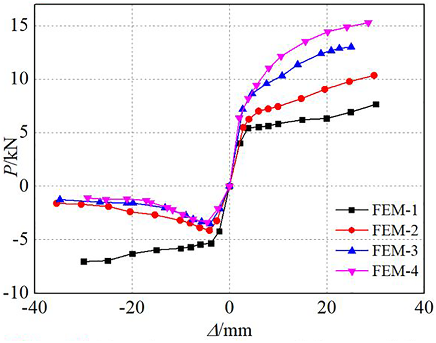
Envelope curves of the models.
Ultimate loads of the models.
FEM: finite element model.
Stiffness degradation
For the models, the slope of the envelope curves has a sudden change at the displacement of ±5 mm, and the curves are basically linear with a displacement of less than ±5 mm, indicating that there is significant stiffness degradation for the models after the displacement of ±5 mm. Figure 17 shows the curves of stiffness degradation of the models after the displacement of ±5 mm, where k is the lateral stiffness of the models, and Δ has the same meaning as Figure 13(b).
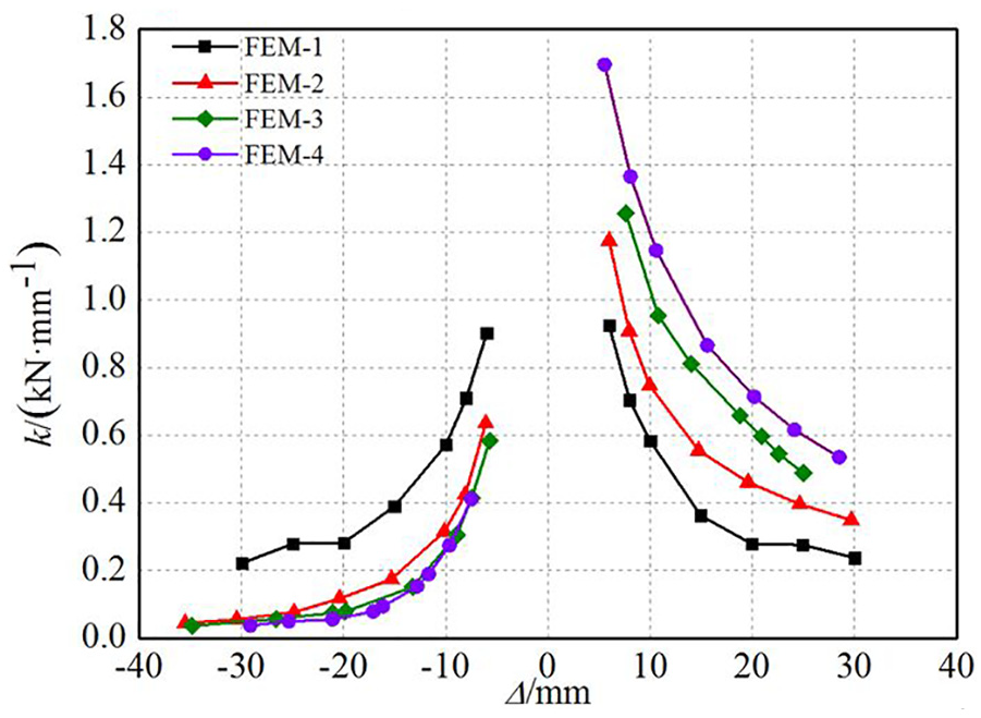
Curves of stiffness degradation of the models.
It can be seen from Figure 17 that the lateral stiffness of the models degrades significantly due to the cumulative damage of material after yielding, such as the extrusion deformation of the dowel and the mortise expansion of Da-Tou. The curves of stiffness degradation of the intact FEM-1 are basically symmetrical in positive and negative loading, and the rate of lateral stiffness degradation is faster at the initial stage, and then the rate slows down with a larger displacement. The reason is that the plastic deformation of the dowel is too large to anchor the Da-Tou, and the lateral loads are mainly resisted by the friction between the members. The curves of the tilting models (FEM-2, FEM-3, and FEM-4) are obviously asymmetrical in positive and negative loading. The initial stiffness in positive and negative loading is greatly different, caused by the smaller vertical loads in negative loading. With a larger tilting angle, the stiffness of the models increases at the same displacement level in positive loading. The main reason is that in positive loading, the extrusion between the members increases significantly subjected to the lateral loads with the increase in tilting angle, which leads to the improvement of lateral bearing capacity. In both positive and negative loading, the lateral stiffness of the models decreases with the increase in lateral displacement, and the change trend is almost the same.
Capacity of energy dissipation
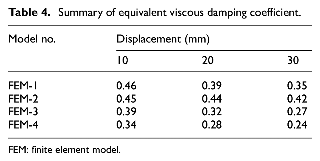
In this article, equivalent viscous damping coefficient he is chosen to represent the energy dissipation capacity of Tou–Kung subjected to cyclic loads. Figure 18 shows the relationship of he and the lateral displacement Δ, and Table 4 lists the he of the models at the displacement of 10, 20, and 30 mm.
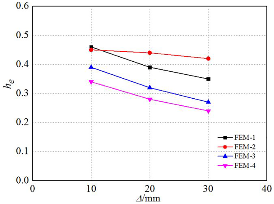
Relationship of he and Δ of the models.
Summary of equivalent viscous damping coefficient.
FEM: finite element model.
It can be seen from Figure 18 and Table 4 that the he of the models decreases with a larger displacement, and the energy dissipation capacity of the models (except for FEM-2) becomes smaller with the increase in tilting angle of the models at the same displacement level. The reason is that the extrusion deformation between members in positive loading obviously increased with a larger tilting angle, and the friction force along the Mazha-Tou is larger, and then the capacity of energy dissipation improves significantly. In negative loading, the vertical loads of the models decrease with a larger tilting angle, and the friction force along the Mazha-Tou is smaller, and then the capacity of the models decreases. However, the he values of FEM-1, FEM-2, FEM-3, and FEM-4 at the displacement of 30 mm are 0.35, 0.42, 0.27, and 0.24, respectively, which are still larger than those of reinforced concrete structures (Kun et al., 2017), indicating that the tilting Tou–Kung has a better capacity of energy dissipation.
Conclusion
The following conclusions can be obtained based on the analyses of Tou–Kung sets in historic timber structures:
The failure modes of intact Tou–Kung sets were the compressive fracture of Da-Tou under vertical load, the shear failure of the dowel at the Da-Tou, and the slipping between Da-Tou and Pingban-Fang under lateral cyclic loads. The tilting Tou–Kung almost had the same failure modes of intact Tou–Kung sets.
Based on the numerical simulation of Tou–Kung, the validation of FEM and experimental results was carried out. It is shown that although there was an acceptable error between both the curves, the curves of FEM coincided quite well with the experimental curves in general.
The relationship of vertical load and vertical displacement and the hysteretic loops of lateral load and displacement were obtained and analyzed. It can be seen that the vertical initial stiffness and bearing capacity of the models decreased with the increase in tilting angle. Also, the hysteretic loops of the tilting models subjected to cyclic loads are asymmetrical in positive and negative loading, and the asymmetrical degrees of the curves are much significant with a larger tilting angle of the models.
The rate of lateral stiffness degradation is faster at the initial stage, and then the rate slows down with a larger displacement. The changing trend of stiffness degradation of the models is almost the same.
The equivalent viscous damping coefficient of the models decreases with a larger displacement, and the energy dissipation capacity of the models (except for FEM-2) decreases with the increase in tilting angle at the same displacement level.
Footnotes
Declaration of Conflicting Interests
The author(s) declared no potential conflicts of interest with respect to the research, authorship, and/or publication of this article.
Funding
The author(s) disclosed receipt of the following financial support for the research, authorship, and/or publication of this article: The authors would like to thank National Natural Science Foundation of China (Grant No. 51678478), National “Twelfth Five-Year” Plan for Science & Technology of China (Grant No. 2014BAL06B03), Shaanxi Key Scientific and Technological Innovation Team (Grant No. 2019TD-029), and Xi’an University of Architecture & Technology for their generous support of this research work.