
Abstract
Recently, the single haunch with specifications such as less invasive and architectural consistency, and easy to practice have been adopted as one of the considered retrofitting options for deficient reinforced concrete beam-column joints. In this article, by analytical evaluation, the influence parameters such as haunch to beam stiffness ratio, haunch inclination angles, and mounted position were investigated. Analytical equations were also proposed for haunch to beam stiffness ratio in terms of both shear interaction between haunch and beam-column members and reduction of joint shear demand. Moreover, five exterior beam-column joint sub-assemblies were fabricated afterwards four of those retrofitted by various cross-sectional area of single steel haunch. Then, all of these beam-column joints and remaining one (as-built joint) were experimentally subjected to cyclic loading. To validate the analytical results, the experimental responses in four limit states including first diagonal core crack in as-built joint, drift ratio 2%, the first diagonal core crack in all the joints, and ultimate state (peak load) were provided for comparison. Also, by definition of an index as vulnerability index in fraction ratio of available joint shear force to joint shear strength predicted by international codes, the obtained vulnerability index of experimental responses were compared to analytical results.
Keywords
Introduction
There are yet numerous vulnerable reinforced concrete (RC) buildings with moment resistant frame (MRF) structure in seismic zones that for the various reasons, such as improperly detailed, low quality concrete in practice, and exploitation time additional loads, require to retrofit seismically. RC beam-column joints display key role in transmission of the gravity and seismic loads from beams to columns. The researchers concluded that the concrete compressive strength,
The deficient MRF structures with low strength concrete and subjected to overloading for joint regions must be retrofitted seismically. Chen (2006) extended initially the haunch retrofit solution (HRS) to shift the hierarchy of damage mechanisms to one in which the RC joint, as a critical component, is protected and damage is forced into the RC beams. The experiments were carried out at the joint sub-assembly level (Genesio, 2012), as well as at structural level (Akbar et al., 2018; Sharma et al., 2014) to evaluate the performance of the HRS. These researchers found that the efficiency of the retrofit solution depends highly on the performance of the anchorage system used to connect the haunch element to RC members and in cases where anchors are bonded, they fulfill their purpose well, forming a clear beam hinge, instead of a joint-shear failure (Genesio, 2012; Sharma et al., 2014). In similar studies, the researchers used the technique of local steel bracing haunch members experimentally and numerically (Khalili et al., 2015; Kheyroddin et al., 2016; Sharbatdar et al., 2012a, 2012b). Because of more satisfaction the retrofit solution architecturally, the researchers with various objects recently investigated the capability and performance of single haunch as a less-invasive retrofit solution for RC frame beam-column joints (Kanchana Devi et al., 2018; Kheyroddin et al., 2016, 2019; Truong et al., 2017). Zhou et al. (2012) experimentally studied the seismic performance of the RC frames with viscous damper haunch braces under sinusoidal waveform steady-state excitations. The results of their investigation showed that the beam-column joint internal forces of the RC frame with viscous damper haunch braces were greatly reduced. Yang et al. (2012) developed a new type of SRC (steel-reinforced concrete) beam transfer structure with supplemental energy dissipation haunch braces to improve the seismic behavior.
For the first time, Kheyroddin et al. (2016) evaluated the single haunch feasibility usage (“one-way steel prop and curbs”) as less-intervention retrofit option with and without steel revival sheets on the beam experimentally. The main idea was usage of a haunch which initially be less-invasive architecturally meanwhile acted as a fuse element to increase the rigidity and strength of deficient system. In another study, they also investigated the effect of different cross-sectional areas of steel haunch on behavior and force transmission mechanism between RC members and single haunch analytically and experimentally (Kheyroddin et al., 2019).
In this study, the affective key parameters on transferred internal forces at an exterior beam-column joint sub-assemblage retrofitted by single haunch are investigated. Moreover, analytical equations are also proposed for haunch to beam stiffness ratio in terms of both shear interaction between haunch and beam-column members and reduction of joint shear demand. Moreover, in experimental part, the influence of various cross-sectional area of the steel haunch is evaluated on reduction of demand joint shear force and experimental responses are compared to obtained results by analytical formulations.
Experimental program
For investigation of efficiency of the single steel haunch practically as a retrofitting option in demand reduction of joint shear force at RC frames, five ½ scaled RC exterior beam–column joints were fabricated and casted. Figure 1 and Table 1 show the geometric properties and reinforcement details of the five half scale two-dimensional (2D) experimental specimens: as-built specimen JS and four retrofitted specimens RJS1, RJS2, RJS3, and RJS4. Average 28-day compressive strength
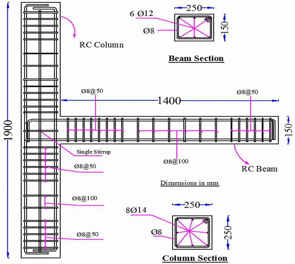
Geometric dimensions and reinforcement details of all specimens (in mm).
Characteristics of the tested experimental specimens.
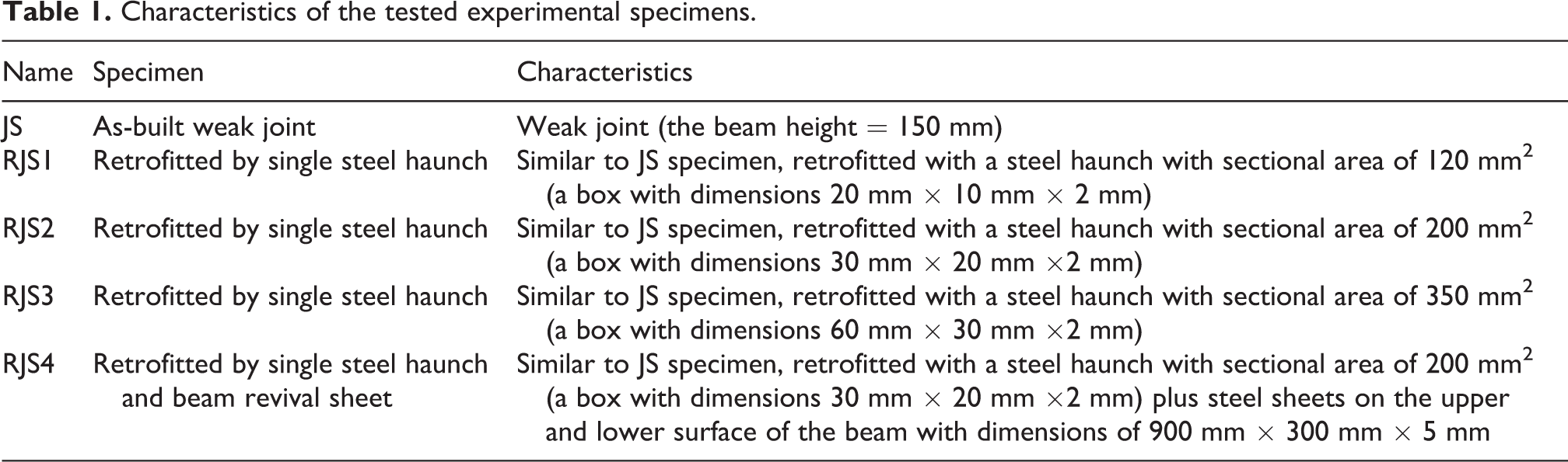
The overview of the test setup with the specimen supports and other key components are shown in Figure 2(a). The column was supported by a hinge connection at one end and a roller on the other end that was erected on laboratory’s strong floor and the axial load of the column was equal to 0.15Pn = 170 kN. The cyclic loading history of tests shown in Figure 2(b) was based on displacement control imposed.
Condition loading of the test: (a) test setup and (b) cyclic loading history.
Analytical study
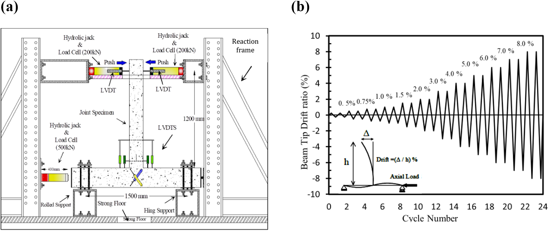
The suggested retrofit solution, “single steel haunch and curbs,” can be utilized for both the interior and exterior beam-column joints as shown in Figure 3(b). The exterior beam-column joints are more vulnerable joints during the earthquake among the other types and categories of beam-column joints, so in this study an exterior T-shape joint is analytically considered.
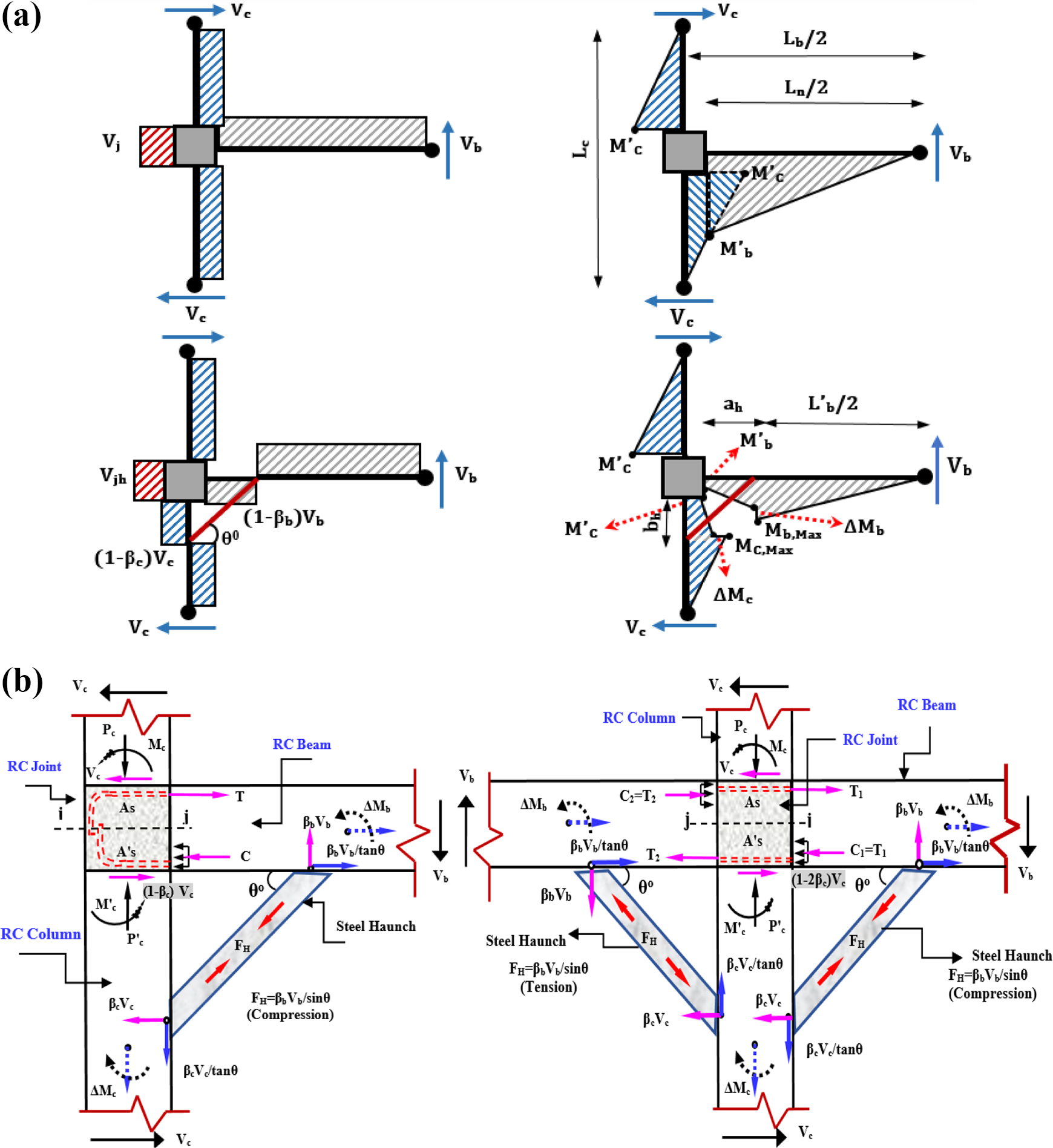
Internal forces in the RC joints: (a) governed forces on the retrofitted exterior and interior joints and (b) force diagrams of the as-built and retrofitted joints.
Preliminary analytical study
Generally, the analytical formulations established by Chen (2006) and Pampanin et al. (2006) about the RC joints retrofitted by double haunches are adopted in this study for the single HRS as follows. Therefore, internal force diagrams of shear and bending moment for the as-built and retrofitted joints (by single haunch) subjected to the lateral force of Vb can be plotted as Figure 3(a). Here, also for special study of influence of the single haunch on the RC joint shear force, the governed internal reaction components on that are proposed and presented as Figure 3(b).
Based on Figure 3(a), under the applied load Vb at beam tip, the maximum of beam bending moment, Mb(max) , occurs in a distance of ah from the column face (connection position of the haunch to beam) as follows
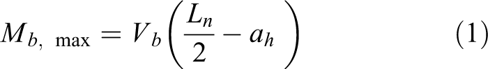
ah is the horizontal projected length of the haunch. Ln is the net beam spans length (from face to face of the columns).
From Figure 3(b), if the vertical and horizontal components of the haunch axial force in the connection region to the beam and column are supposed, respectively, βbVb and βcVc as coefficients of the beam and column shear forces, then Fb and Fc equal equations (2) and (3), respectively

And

Thus, the beam and column shear coefficients βb and βc are related together as
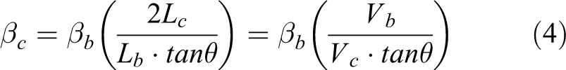
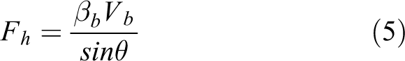
where θ is the haunch inclination angle into horizontal line as shown in Figure 3, and Lb and Lc are the total beam span length (from center line to center line of columns) and the total inter-story height (from center line to center line of beams), respectively. Also, βb and βc are described in the following paragraphs. Moreover, the single haunch axial force, Fh , as shown in Figure 3(b) can be obtained as equation (5)
As shown in Figure 3(a), the bending moment at the column face,

where
Also,
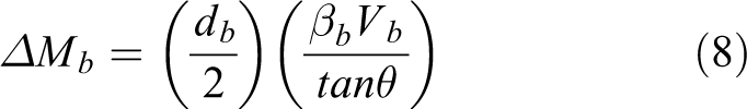
where db is the depth of the beam.
As illustrated, the
where bh
is the distance between haunch connection place to column and the joint interface as shown in Figure 3(a). Ib
and Ab
are, respectively, the cracked moment inertia and cross-sectional area of the RC beam section, and
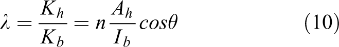
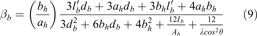
where n is known as (Eh/Ec ), in other words, the ratio of the haunch material elasticity to concrete elasticity. Also, Ah is cross-sectional area of the haunch element. It should be noted that the column shear coefficient βc can be obtained using equation (4) by determining the value of βb .
Evaluation of effective factors on shear coefficients β and joint forces
Using equations (4), (9), and (10), the influence of cross-sectional area of haunch on the beam and column shear coefficient, βb and βc , for various values of the haunch angles (θ) and its erection position α (ah/lb ) were investigated. For various amounts of α equal to 0.1–0.3, by increasing Ah , both the βb and βc coefficients enhance monotonically. Also for any given amount of α and also Ah , with the increase in the haunch angle from 20 to 60 degree, the βb increases while the column shear coefficient βc decreases drastically. It indicates that the very flat angle of haunch (i.e. θ < 30°) cannot be effective in reduction of the column face bending moment or joint shear demand and moreover increases the shear demand in column considerably. Also for any given amount of α and Ah , for the haunch angle of less than 60°, βc is larger than βb . Although for any given amount of α and Ah , both haunch angle 45 and 60 degree provide approximately same values of βb , but haunch angle 45° and more than 60° produce shear demand in column which is not desirable. Therefore, the researchers also have accentuated that for less shear demand in beam and column the coefficient β must be less than 2.0 (Chen, 2006; Pampanin et al., 2006).
The variations both of the βb and βc with α (at range of 0.05–0.5) were evaluated for various cross-sectional area and inclination angles of the haunch. In Figure 4, the graphs related to various cross-sectional areas of the haunch for angle of 45° are typically presented. Generally, it can be observed that the maximum values of βb and βc depend on the haunch sectional area and angle and are obtained for α lesser than 0.2 and for the larger values of that with the increase of the haunch sectional area and angle decreases remarkably and for α equal 0.5 reaches to its minimum values. Also with the increase of the haunch cross-sectional area and for any given haunch angle, the maximum amounts of βb and βc are attained in the lesser values of α or in other words the values of α corresponding to maximum of βb and βc decrease.
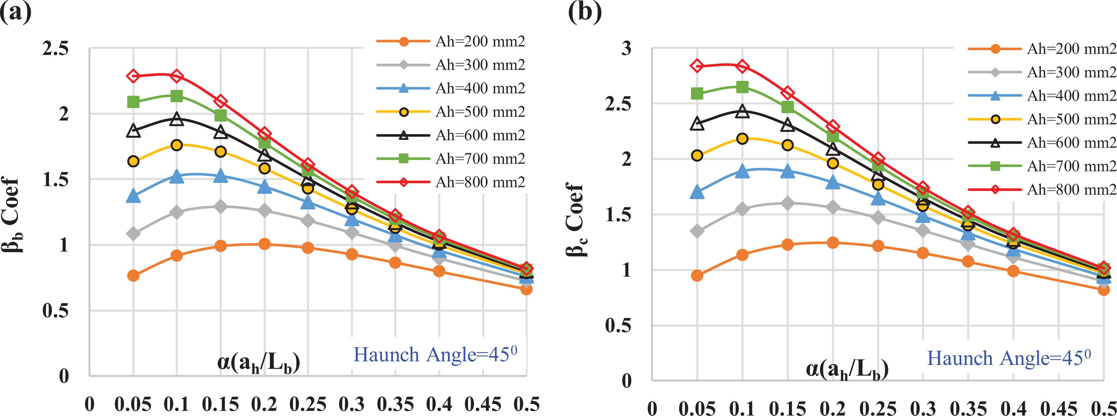
Variations of the shear coefficients versus amounts of α for various haunch sectionals areal and angle of 45° (db = 400 mm): (a) βb coefficient and (b) βc coefficient.
It is worth noting that at the haunch inclination angle of lesser than 30°, for any given value of α and Ah , the coefficients of βc are approximately two to three times larger than βb correspondingly. Therefore, as already mentioned, it will lead to significant enhancement of the shear demand in the column so that for a weak column building system specially that would not be never desirable. On the other hand, at the haunch inclination angle of 45°–60°, it was observed that the amount of βc to βb ratio varies from 1.25 to 0.75 approximately.
As shown in Figure 3(b), the horizontal joint shear force Vjh , at the mid-plane (section i:i) of the exterior retrofitted joint assemblies are respectively proposed as equation (11)
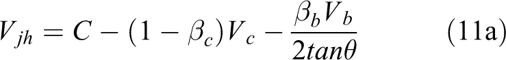
Or
Where T and C are the tension/compression forces in the beam longitudinal bars and concrete block, respectively, and Vc is the column shear force as shown in Figure 3. In addition, Zb is the lever arm of the beam internal forces at the column face.
Unlike what is presented by other researchers for Vjh
, herein the authors opine that some of the horizontal components of the single haunch axial force (e.g.
As illustrated in equations (6) and (11), both
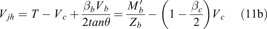
Influence amount of α for various haunch sectionals areal and inclination angle of 45° in reduction of: (a) beam moment and (b) joint shear demand (db = 400 mm).
The most impact values of α in reduction of beam moment and joint shear demand developed about 0.3 to 0.35 for haunches with highest sectional area (i.e. Ah = 800 mm2) to about 0.5 for lowest sectional area (i.e. Ah = 200 mm2) while as before mentioned the maximum values of βb and βc are provided at value of α < 0.2.
The variations of
Proposal analytical equations for shear coefficients β and joint forces in λ ratio
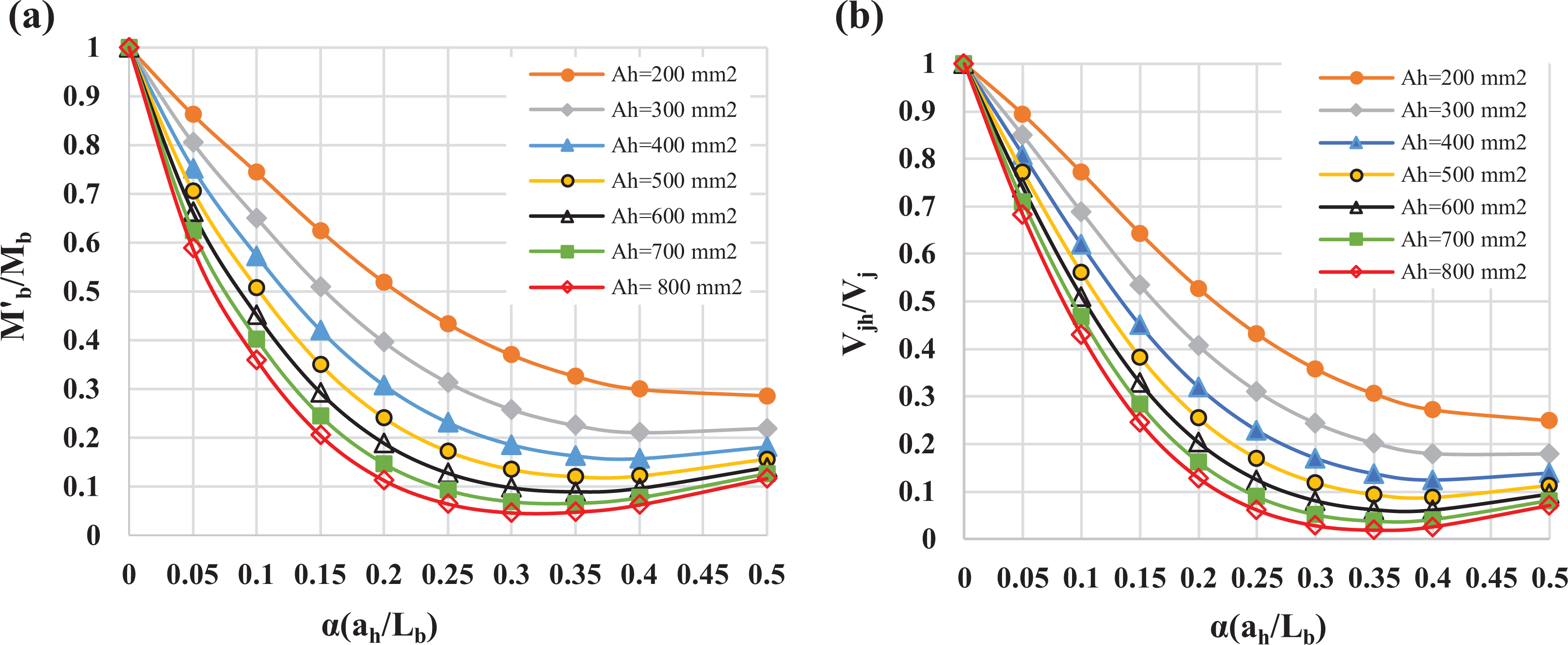
In the event that the optimum state of the haunch application for retrofitted joints be considered as α = 0.15 and θ = 45°, then based on the above analytical data, the variations of β-coefficient and also
Proposed logarithmic equations in haunch to beam stiffness ratio of λ: (a) for beam and column shear coefficient (βb
and βc
) and (b) for both ratios of


In addition, based on equations (13a) and (13b) by increase of λ-factor in the range 0.22 × 10⁻⁵ to 1.8 × 10⁻⁵ (1/mm2), corresponding to variations of the βb
coefficient at the range from 1 to 2.70, both ratios of


Design of the single steel haunch
The step-by-step process design of the single HRS after opting for its material can be stated as follows: Selection of a primal values for the haunch geometry (Ah
, Lh
, and θ) and determination of α ratio. Computation of the axial stiffness of the single haunch and λ ratio using equation (10). Evaluation values of βb
and βc
using equations (9) and (4), respectively. Estimation of the haunch axial force (Fh
) and internal forces in the beam, column, and joint core for a given beam tip load demand. Evaluation of available capacity in the RC joint sections and control of undesirable failure modes based on the strength hierarchy stated by Pampanin et al. (2006). Revise and repeat steps 1–5 for achievement to desired strength hierarchy.
As shown in Table 1, the haunches were designed based on the obtained analytical results (section “Analytical study”) and mentioned design processes so that the beams bearing capacity increase under overloading cyclic condition; moreover, the joints shear demand force reduced. Therefore, by choosing the 500 mm length and 37° inclination angle (Lh = 500 mm and θ = 37°, that is, α = 0.17) the parameters of ah and bh for all of the retrofitted specimens were 400 and 300 mm, respectively. The amount of Ah for RJS1, RJS2, RJS3, and RJS4 specimens were 120, 200, 350, and 200 mm2 with steel grade 300. Correspondingly, based on the test material, the yielding stresses σy and elastic modulus Eh were 330, 312, 320, and 318 MPa and 196, 210, 187, and 195 GPa, respectively. Thus, for the designed haunches with equivalent axial stiffness Kh , 47,000, 84,000, 131,000, and 78,000 kN/m, the beam shear coefficient βb in accordance with equation (9) for these specimens are 1.6, 2.0, 2.3, and 2.0, respectively.
Test results and discussion
In this part, nominal principle stresses

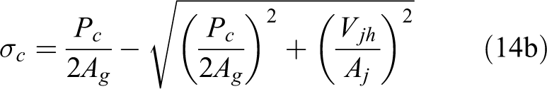
where Pc is the effective column axial compressive load in the joint region, Ag is the column gross section area, Vjh is the nominal joint shear force at the mid-plane of as-built and retrofitted joints that can be expressed as equation (11), and Aj is the effective joint area.
As presented in the analytical part, as β-coefficient with the steel haunch stiffness (increasing of haunch section area) increases both of beam bending moment at column face (M′b ) and the joint shear force Vjh usually decrease remarkably. For validation of the analytical results in estimation of β-coefficient and also the joint shear force, the joint principle stress level at several limit states were estimated using equation (15) and the results compared with concrete cracking behavior of as-built and retrofitted joints core. For evaluation of the joints principle stress level, there were four limit states considered: (1) the first diagonal cracking in as-built joint core at beam tip load of equal to 12.5 kN (Vb = 12.5 kN); (2) drift ratio of 2% in the retrofitted beam-column joints; (3) the first diagonal crack in retrofitted joints core; and (4) peak load capacity (Vb,max ) of all beam-column joints.
The researcher results for exterior beam-column joints present the different values for principal tension/compression strength from
Table 2 summarizes the analytical and experimental outputs obtained based on both βpre
and βexp
values, respectively, in the terms of β-coefficients, haunch axial force Fh
, and beam tip force Vb
corresponding to the above mentioned limit states. In addition, Figure 7 shows the compared normalized values of υih
, σt
, and σc
for all joint specimens analytically and experimentally. In these figures υih
and σt
have been normalized by
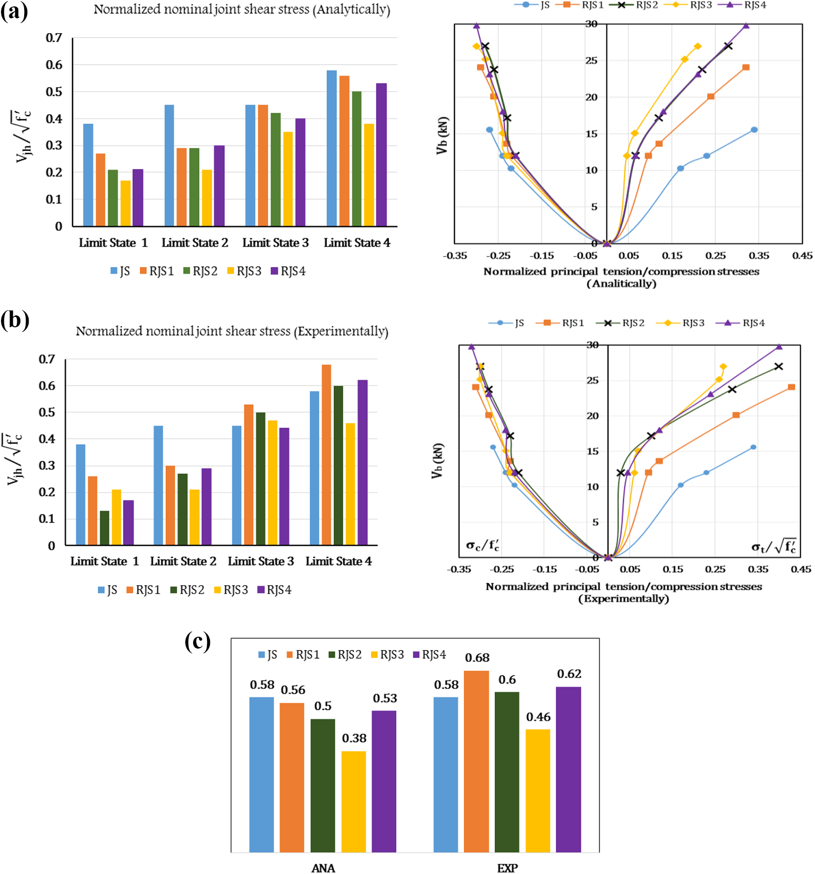
The normalized value of nominal shear stress and principal tension/compression stresses of the joint specimens at four limit states: (a) analytically, (b) experimentally, and (c) the comparison of analytical and experimental at fourth limit state in terms of nominal shear stress.
Comparison of the analytically predicted and experimental results of specimens in the four limit states.
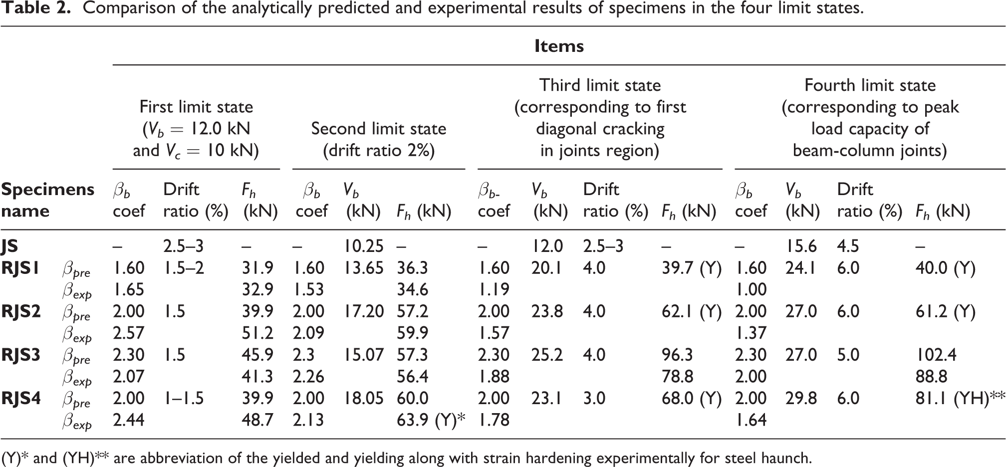
(Y)* and (YH)** are abbreviation of the yielded and yielding along with strain hardening experimentally for steel haunch.
1. The βpre
and βexp
are defined as the analytically and experimental shear coefficients calculated by equations (9) and (5), respectively. For derivation of βexp
from equation (5), the experimental haunch axial force Fh,exp
corresponding to beam tip load, Vb
, can be expressed as equation (15)
2. It has been supposed that when the steel haunch reaches to its yielding force experimentally and the analytically predicted steel haunch force Fh,pre
equals the Fh,exp.
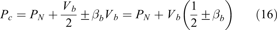
. 3. Each RC member is provided by an in-closure steel curb; consequently, the force components of haunch approximately distribute throughout member sections uniformly. 4. The effective column axial load Pc
on joint region can be estimated as equation (16) with contribution of the provided column axial compression force (PN
= 170 kN), the haunch vertical force component equal to βbVb
(or βcVc tanθ) and 1/2 of beam tip load (Vb
/2) which both of those can act as a compression or tension force on the joint region when the beam tip is subjected to pull and push cyclic loading 5. It has been supposed that lever arm of beam internal forces at column face in calculation of joint horizontal shear force are about 120 mm (equal to 0.9 beam affective depth) for all specimens.
where Eh
and Ah
are the module elasticity and cross-sectional areal of steel haunch, respectively. εh
is attained from average of read axial strains of mounted strain gages on the three middle section of steel haunch. Based on the equation, the hysteresis envelop curve of haunch axial force versus beam tip displacement for retrofitted beam-column joints are plotted as Figure 8(b). Thus, in accordance with Table 2, the average of experimental haunch axial force Fh,exp
corresponding to any given beam tip displacement or load Vb
at positive and negative directions can be provided from Figure 8.
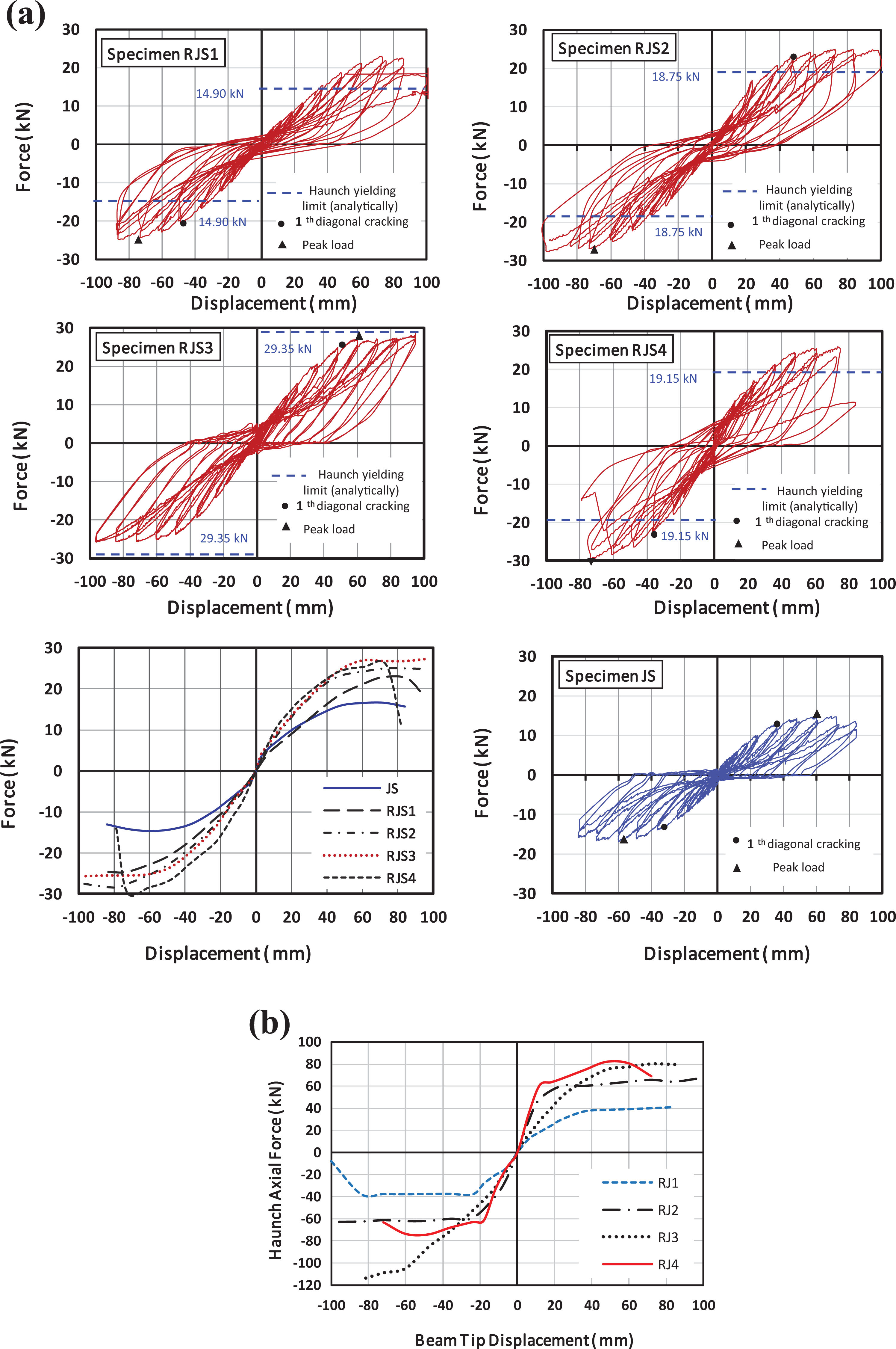
Force–displacement behavior for all the tested specimens: (a) force–displacement hysteresis loops and envelope curves of the beam tip, and (b) hysteresis envelop curves of the haunches axial force for the retrofitted joints.
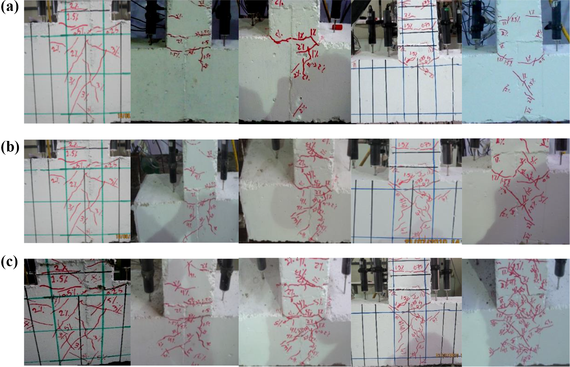
Cracking patterns of the joints core at four limit states: (a) the first and second limit states, (b) the third limit states (first diagonal cracking in core), and (c) the final limit states (corresponding to peak load capacity Vb,max ).
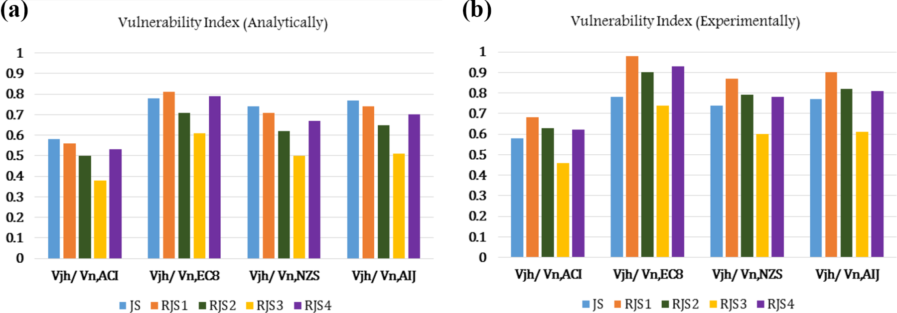
Comparison of vulnerability index (VI) at ultimate limit state for all specimens: (a) analytically and (b) experimentally.
In Figure 8(a), force–displacement hysteresis loops of the beam tip for all specimens and comparison of their envelope curves are also presented. As illustrated in Table 2, at the first limit state, the steel haunches at each retrofitted joint are not yielded and in accordance with Figure 8 for given value of Vb = 12.0 kN, and the normalized values of υih , σt , and σc in the specimen JS are at ranges of 1.6–2.6, 2.4–5.0, and 1.05–1.14 times more than that in the retrofitted specimens, respectively. Consequently, as clearly observed in Figure 9(a), there are no evidences of cracking in the joint core of retrofitted specimens on the contrary of the diagonal cracking of as-built joint core.
Generally, as shown in Figure 7(a), based on the analytical outputs by increase in cross-sectional area of steel haunch, the nominal joint shear demand decreases significantly. In the second limit state (when the beam tips displacement is equal to 24 mm) although the retrofitted specimens at drift ratio 25 suffer 14%–50% more load as compared to joint JS (when Vb = 12.0 kN and first diagonal cracking) nonetheless the normalized values υih , σt , and σc of those were 0.46–0.67, 0.28–0.56, and 0.95–1.0 times of that, respectively, and there is also no evidence of serious diagonal cracking at them joint core (see Figure 9(a)).
It is worth noting that based on the experimental data at this limit state only the steel haunch of specimen RJS4 reaches to its yielding stress. Also it can observed that there are fit conformity between the analytical outcomes and the experimental responses for all the evaluated terms based on the βpre and βexp provided by equations (5) and (9).
The experimental and analytical results of all specimens in the third and fourth limit states are summarized in Table 2 and Figure 9(b) and (c), respectively. As indicated in Table 2 unlike to two previous limit states, here exists a significant difference between the analytically predicted and experimental shear coefficients, βpre and βexp which can be due to the appearance of nonlinear behavior of materials including cracking propagation in concrete, buckling and yielding of steel haunch, and yielding of beam longitudinal bars in the retrofitted joints (refer to Figures 8 and 9 and Table 2).
Hence, because of decline efficiency of the haunches in force transmission, the whole produced amounts of investigated terms based on βexp
(as Table 2) are more than βpre
except in the terms of βb
and βc
(e.g. see Figure 7(c)). It indicates that in two last limit states for investigated terms based on the experimental observations, the produced values from βexp
seem more actual than βpre
. Also based on both the βpre
and βexp
values, the steel haunches in all retrofitted joints except in RJS3 are yielded. Also as presented in Table 2 and Figure 9(b), the first diagonal cracking in the retrofitted joints developed at upper drift ratio of beam tip with respect to the joint JS; moreover, the values of Vb
increase at range of 67%–110% as well as the beam moment demand at column face
As shown in Figure 7(b), the normalized amount of σt for the as-built joint JS in first diagonal cracking is 0.23 with existence of single stirrup in the joint core that is lesser than the value reported (i.e. value of 0.29) by Priestley (1997) for the exterior RC joints with beam bars bent into the joint zone (by joint failure). In addition, these normalized amounts based on βpre and βexp in the retrofitted joints vary at range of 0.18–0.24 and 0.24–0.3, respectively. Again the normalized value of υih for the joint JS in first diagonal cracking is 0.45 while this value in the retrofitted joints are about 0.35–0.45 and 0.44–0.53 corresponding to the βpre and βexp , respectively.
Last column of Table 2 and Figures 8 and 9(c) indicate the output results of all joints at the fourth limit states (corresponding to peak load capacity Vb,max
of the beam-column joints) for various evaluated terms. As shown in Figure 8(a), the retrofitted joints reach their Vb,max
at upper drift ratio as compared to joint JS and also in this limit state the value of Vb,max
growth about 55%–91% and the beam moment demand at column face
The normalized amount of σt in the joint JS (without joint failure) corresponding to Vb,max is 0.34 with existence of single stirrup in joint core that is lesser than value of 0.42 reported by Priestley (1997) (with joint failure). Moreover, in the retrofitted joints these amounts based on the βpre and βexp vary at ranges of 0.21–0.32 and 0.27–0.43, respectively. The normalized value of υih for joint JS is 0.58 while these values in the retrofitted joints are about 0.46–0.56 and 0.46–0.68 for both βpre and βexp , respectively. It should also be noted that according to experimental responses (see Figure 8(a)) at this limit state, in spite of less bearing capacity of the as-built joint (0.5–0.65 times) with respect to the retrofitted joints, the cracking propagation of its core is approximately more than those (see Figure 9(c)).
As shown in Figure 1, although there were not enough joint reinforcement in the tested joints as that prescribed in updated codes, their normalized values of σc
at last limit state were lower than 0.5 (see Figure 7). Generally, to prevent premature joint shear failure, the available joint shear strength (Vn
) shall be more than the joint shear demand (Vjh
). There are various international codes such as the American standard ACI 318-14 (ACI Committee 381, 2014), the European code, EC8 (European Committee for Standardization, 2004), the Japanese code Architectural Institute of Japan (AIJ, 1999), and the NZS 3101:2006 (2006) that have a formula for estimating both Vn
and Vjh
. Based on the current code provisions, the value of Vn
is majority defined only as a function of the concrete compressive strength as
Generally, definition of the horizontal joint shear demand Vjh, demand
are quite similar at all of the codes as γAsfy
-Vcol
, with this difference that the tension force T of beam longitudinal bars vary with an over strength factor (γ) of 1.2–1.35 for the mentioned codes. The value of Vjh, demand
for all tested specimens (the RC beam with
In Table 3, the values of Vjh obtained by analytically predicted and experimental results for all specimens are compared to Vn estimated by various international codes in the ultimate limit state (peak load capacity). In order to evaluate core damage proportion of the experimented joint, hereon is defined a fraction ratio of Vjh over the joint shear strength estimated by the codes (Vn, code ) as a Vulnerability Index (VI) as follows

Comparison of the joint shear strength among analytically predicted, experimental results and codes estimations at ultimate limit state.
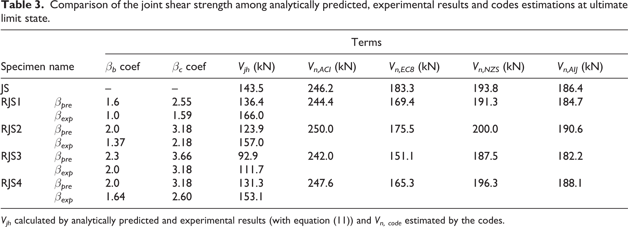
Vjh calculated by analytically predicted and experimental results (with equation (11)) and Vn, code estimated by the codes.
When the fraction ratio approaches 1, it means that the extreme damage have occurred and mutually when this fraction limits to 0, there is a minimum amount of damage in the joint core.
Figure 10 presents compared experimental and analytical VI values calculated for all specimens based on Table 3. As indicated in Table 3 and Figure 10, the ACI codes estimate more values for Vn as well lower values for VI than other practice codes. On the other hand, the European Code by accounting of the affective column axial load provides least values for Vn as well more values VI as compared to other practice codes. Also, for all experimented specimens, the available joint shear force is less than joint shear demand predicted by codes and those are less than nominal joint shear strength estimated by practice codes namely, Vjh < Vjh, demand < Vn, code . Moreover, the JS and RJS3 specimens have, respectively, most and least VI values based on the analytical prediction by international codes. On the other hand, the calculated experimental VI values for RJS1 and RJS3 are most and least values, respectively.
Conclusion
This article focuses on the efficiency of single haunch system as one of retrofitting strategies with benefits such as less-invasive and intervention, easy implementation, and desirable architecturally for RC frame joints. In analytical part, equations for exterior and interior RC joint shear demand were represented using analytical development of shear forces interaction mechanism between single haunch and RC members In experimental part, four ½ scale exterior joint sub-assemblies were retrofitted by single steel haunch with cross-sectional area of 120, 200, 350 mm2 and later 200 mm2 by beams steel revival sheets To validation of the analytical results with experimental responses in the four limit states utilizing Mohr’s circle theory, the principal stress levels of the joints core were evaluated. The experimental and analytical results comparisons showed that there is good conformity at two initial limit states for the above mentioned terms except at two last limit states due to occurrence of nonlinear behaviors in materials. Normalized analytical and experimental values of σt
in the retrofitted specimens to as-built were around 0.38–0.77 and 0.41–0.71, respectively, at drift ratio 2%; moreover, bearing capacity ratio of those were about 1.33–1.67. Also, these ratios at ultimate state were around 0.62–0.94 and 0.79–1.27; moreover, the bearing capacity ratio were about 1.55–1.91. A ratio of available joint shear force to shear strength predicted by international codes was defined as joint vulnerability index (VI) for comparison of the experimental and analytical results at the ultimate state. The ACI and EC 8 codes by producing minimum and maximum amounts of VI estimated, respectively, most and least values for the joint shear strength. It is found that based on the international codes predictions, by increase of the haunch cross-sectional area, Ah
(or in other word value of the λ), the amount of joints vulnerability as well as vulnerability index (VI) decreases.
Footnotes
Declaration of conflicting interests
The author(s) declared no potential conflicts of interest with respect to the research, authorship, and/or publication of this article.
Funding
The author(s) received no financial support for the research, authorship, and/or publication of this article.