
Abstract
Concrete-filled steel tubular (CFST) columns have been extensively studied and widely used in practice. Existing research has shown that non-circular CFST columns is much less ductile than their circular counterparts, particularly when thin/high strength steel (HSS) tubes and high-strength concrete are used. To address this problem, a new form of CFST columns has recently been proposed by the first author. The new column consists of a steel tube filled with concrete that is confined with HSS spiral reinforcement typically with a yield stress exceeding 1000 MPa. These columns, referred to as confined concrete-filled steel tubular (CCFST) columns, also maintain the ease for connection to CFST or steel beams. This paper presents the results of a series of concentric axial compression tests on such columns of square cross-section to demonstrate their advantages. The experimental program included 13 CCFST columns, four CFST columns without internal spiral confinement, two hollow steel tube (HST) columns, and 11 circular HSS spiral-confined concrete columns. Three different compressive strengths and three HSS spiral pitches were examined in the experimental program. The CFST columns, HST columns, and HSS spiral-confined concrete columns were all tested under axial compression to gain a good understanding of the confinement mechanism in a CCFST column. The test results show that the new columns possess much greater ductility than those without internal spiral confinement, although the use of HSS spirals increases the steel volume by only a small percentage. It is also shown that the axial load-axial strain curve of a CCFST column can be conservatively predicted by summing the axial load-axial strain curves of the hollow steel tube without local buckling, the HSS spiral-confined concrete core, and the sandwiched concrete between the two.
Introduction
Concrete-filled steel tubular (CFST) columns have been extensively studied and widely used in practice due to their many advantages over traditional reinforced concrete (RC) columns (e.g. Fam et al., 2004; Han et al., 2008; Ou, 2013). In a CFST column, the steel tube provides part of the axial load resistance of the column and at the same time exerts a lateral confining pressure to the infilled concrete when the lateral dilation of the concrete exceeds that of the steel tube. The confining pressure can significantly enhance the strength and ductility of the infilled concrete (e.g. Han et al., 2008; Teng et al., 2013). The common sectional forms of CFST columns are either circular or rectangular. While rectangular CFST columns (including square columns as a special case unless the differentiation between rectangular and square columns becomes necessary) are often preferred in building structures mainly for their ease of connection to beams (Han et al., 2008, 2014), it is well known that they are much less ductile than their circular counterparts, particularly when thin/high-strength steel (HSS) tubes and high-strength concrete (HSC) are used (Han et al., 2014; Sakino et al., 2004; Thai et al., 2014; Uy, 2001), which is a major concern for structures designed to resist seismic loading. In a rectangular CFST column, the steel tube is much less effective in confining the infilled concrete and more susceptible to local buckling than that in a circular CFST of similar geometric and material properties (Sakino et al., 2004; Teng et al., 2013).
To address the issue of inadequate ductility of rectangular CFST columns, many techniques have been explored. Some researchers proposed to weld internal longitudinal steel stiffeners or shear studs to the steel tube (e.g. Ding et al., 2014; Ge and Usami, 1992; Guo et al. 2011; Tao et al., 2009) or weld internal transverse steel ties to connect adjacent or opposite side plates of the steel tube (e.g. Cai and He, 2005; Huang et al., 2002; Wang et al., 2012). Longitudinal steel stiffeners increase the steel cross-sectional area and are effective in suppressing or delaying the local buckling of the steel tube, and as a result the ultimate load of a CFST column can be enhanced; however, they provides little help to the confinement effectiveness of the steel tube to the concrete (Ding et al., 2014; Tao et al., 2009). In addition, installing longitudinal steel stiffeners inside a rectangular steel tube is labor-intensive and may be difficult when the tube is small. Welding internal transverse steel ties presents the same issues, in addition to causing inconvenience in the casting of concrete.
A more effective ductility enhancement technique is to provide internal confinement to the infilled concrete in a CFST column using various means, including a circular internal normal-strength steel (NSS) tube (e.g. Roik and Bergmann, 1985; Qian et al., 2014), circular NSS spiral reinforcement (e.g. Chen et al., 2018; Ding et al., 2014) and a circular fiber-reinforced polymer (FRP) tube (e.g. Feng et al., 2015; Li et al., 2012). When a circular NSS tube is used to provide confinement to the infilled concrete, yielding has generally occurred due to axial compression when the NSS tube starts to provide confinement to the enclosed concrete, which means that the ability of the steel tube to confine the concrete is compromised for two reasons: (a) the hoop tensile capacity of the steel tube is reduced by the axial compression due to biaxial stress interaction (Calladine, 2000), which is less desirable than if the confinement is provided by NSS spirals; and (b) local buckling of the yielded steel tube may be induced by axial compression (Teng et al., 2013). If an HSS tube is used instead, the HSS tube tends to be thin and is thus likely to buckle well before yielding, and this buckling cannot be effectively constrained by the concrete sandwiched between the circular tube and the rectangular tube (Wang et al., 2017; Xiong et al., 2017).
NSS spirals with a yield stress from 285 MPa to 363.5 MPa have also been explored to confine the infilled concrete in rectangular CFST columns (Chen et al., 2018; Ding et al., 2014). The advantage of NSS spiral confinement over an NSS tube in confining the infilled concrete lies in the fact that the spiral reinforcement is little affected by the axial stresses. However, NSS spirals yield soon after the concrete starts to dilate more rapidly at an axial strain of 0.002–0.003, leading to limited performance improvement of the ductility of CFST columns (Chen et al., 2018; Ding et al., 2014).
Li et al. (2012) proposed the use of an internal carbon FRP (CFRP) tube to confine the infilled concrete in a rectangular CFST column. Feng et al. (2015) subsequently proposed to replace the internal CFRP tube with a glass FRP (GFRP) tube as the latter is much cheaper than the former for the same confinement benefits. In such columns, the concrete core is effectively confined by the FRP tube; therefore, both the ultimate load and ductility of the column can be substantially enhanced. However, the failure of such columns is featured by the brittle rupture of the FRP tube, after which the axial load carried by the column reduces rapidly (Li et al., 2012; Feng et al., 2015). Moreover, the presence of an internal FRP tube leads to inconvenience for certain forms of beam-to-column connections, such as those requiring the longitudinal steel bars of the beam to go through the FRP tube in the column.
The use of an internal FRP confining tube is based on the exploitation of two properties of FRP: a much larger elastic range of strains than NSS and the tailorability of material properties of FRP (the axial stiffness of an FRP tube can be minimized so that it behaves as a confining device only). The obvious advantage of FRP in resisting electro-chemical corrosion over steel is not utilized in this application. These two functions of an FRP confining tube can, to a large extent, be achieved also by HSS spiral reinforcement with a yield stress around or above 1000 MPa. Indeed, existing research has shown that HSS spirals confine concrete very effectively like FRP tubes due to the large elastic range of HSS spirals (Lee et al., 2010; Li et al., 2001; Kim et al., 2016), but the former are much cheaper and much more ductile than the latter.
Against the above background, a new form of high-performance CFST columns with internal HSS spiral confinement has recently been proposed by the first author (Teng et al., 2016). In these columns, HSS spirals are placed inside (and generally close to) the steel tube to provide strong confinement to the infilled concrete mainly to enhance their ductility. The internal HSS spirals are free from attachment to the steel tube as existing experimental research on CFST columns with internal NSS spiral reinforcement has shown that this option leads to greater ductility for a CFST column than when the spirals are spot welded onto the steel tube (Ding et al., 2014). This new form of columns is referred to as HSS spiral (HSSS)-confined concrete-filled steel tubular (HSSS-CCFST or simply CCFST) columns hereafter. Figure 1(a) shows the schematic diagram of a square CCFST with a single HSS spiral while Figure 1(b) shows the cross-section of a rectangular CCFST with three interlocking HSS spirals. Obviously, this concept of internal HSS spiral confinement can be used with all steel tube cross-sectional forms and all sorts of multi-spiral arrangement over the cross-section, with Figures 1(c) and 1(d) showing two examples. This column form can also be used for circular columns although circular CFST columns generally possess much greater ductility than non-circular/polygonal CFST columns. In these columns, the distance between the HSS spiral reinforcement and the steel tube should be minimized to maximize the effectiveness of confinement by HSS spirals although a small distance needs to be kept to facilitate an easy construction process.
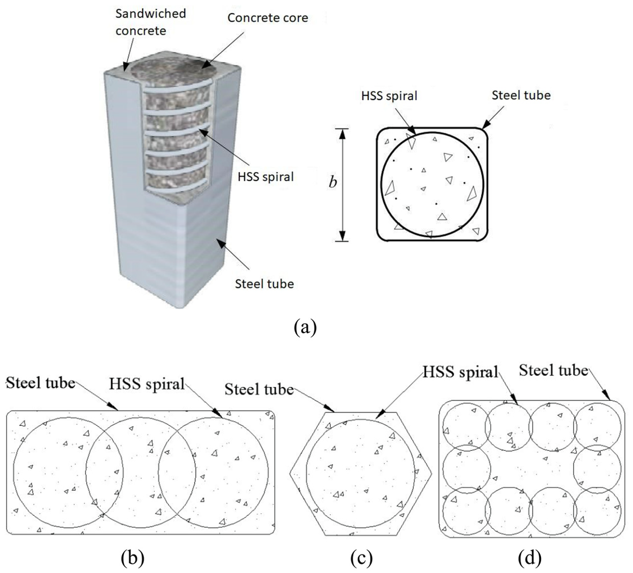
CCFST column and its example sections: (a) square CCFST column and its cross-section, (b) rectangular section, (c) hexagonal section, and (d) multi-spiral layout.
A major research program on CCFST columns has been undertaken by The Hong Kong Polytechnic University in collaboration with Tsinghua University. A recent PhD thesis by Wang (2020) contains most of the research outcomes achieved so far from both experimental and numerical investigations at The Hong Kong Polytechnic University. This paper presents the results of the first ever series of concentric axial compression tests on square CCFST columns with varied concrete compressive strengths (unconfined concrete cylinder compressive strengths ranging from 35 MPa to 120 MPa) and HSS spiral pitches (center-to-center spacing between adjacent turns of steel spirals). Most of these CCFST columns were tested before the end of 2016, and the results of four of these CCFST columns with a concrete strength of 80 MPa have previously been reported at a conference (Teng et al., 2016) to introduce the new column form and to demonstrate the expected advantages of this new column form. It was shown that both the ultimate load and the ductility of the columns were substantially enhanced by HSS spiral confinement (Teng et al., 2016). The new column form as reported in Teng et al. (2016) has already attracted the attention of some other researchers: Hu et al. (2020a, 2020b) recently reported the test results of 11 square CCFST columns with a concrete strength of around 110 MPa under concentric and eccentric axial compression. They confirmed the general conclusion of Teng et al. (2016) that the HSS spiral confinement leads to a significant enhancement in column ductility but only a limited enhancement in ultimate load, which is also consistent with the observations made by the authors’ group on CCFST columns with concrete of such high strengths (Wang, 2020). As the present paper is focused on the structural behavior of CCFST columns with normal strength concrete (e.g. with a cylinder compressive strength lower than 100 MPa), an important topic that has been little studied, the work of Hu et al. (2020a, b) on CCFST columns with concrete of higher strengths will not be further discussed in the paper.
The paper presents the results of concentric axial compression tests on all the CCFST columns with concrete strengths from 35 MPa to 80 MPa conducted by the authors of the present paper. The experimental program presented in the paper included 13 square CCFST columns in three batches covering different concrete compressive strengths and different HSS spiral pitches. The four CCFST specimens reported in Teng et al. (2016) form part of the experimental program. In addition, concentric axial compression tests were conducted on four CFST columns without internal spiral confinement, two hollow steel tube (HST) columns, and 11 circular HSS spiral (HSSS)-confined concrete columns to a achieve a good understanding of the confinement mechanism in CCFST columns.
Experimental program
Test Specimens
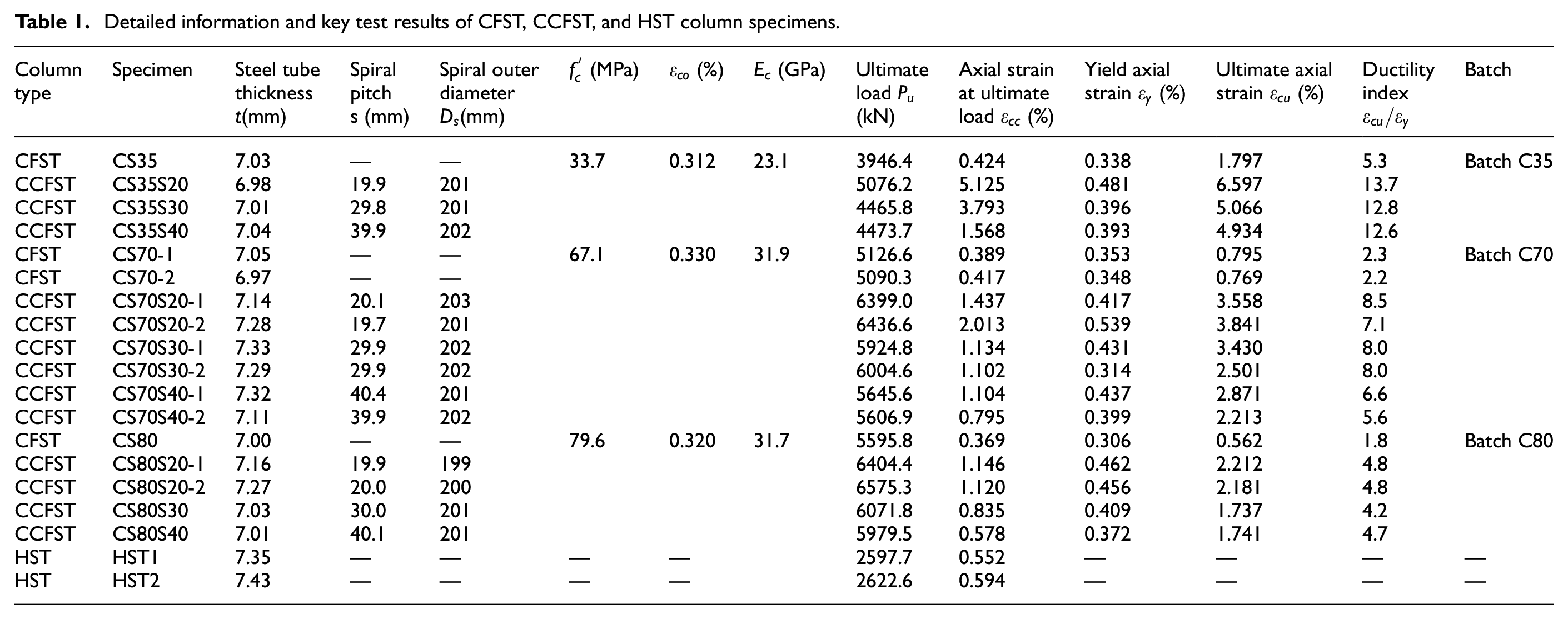
A total of 19 square column specimens of three types were prepared and tested, including 13 CCFST columns, 4 CFST columns, and 2 HST columns. All column specimens had a height of 600 mm. The key test variables were the spiral pitch (nominal values: 20 mm, 30 mm, or 40 mm) and the concrete compressive strength (target concrete cylinder compressive strengths: 35 MPa, 50 MPa, or 80 MPa). It should be noted that the actual cylinder compressive strength of the concrete with a target strength of 50 MPa reached around 70 MPa unexpectedly due to the less than satisfactory control by the commercial concrete supplier. Table 1 provides the detailed information of the test specimens.
Detailed information and key test results of CFST, CCFST, and HST column specimens.
The square steel tubes were seamless cold-formed tubes from a local supplier and had an outer corner radius of 18 mm. They had a nominal outer width of 220 mm and a nominal thickness of 7 mm, leading to an outer width-to-thickness ratio of 31.4, which is smaller than the limit
The HSS spirals were cold-bent from 5-mm-diameter straight steel bars by a local supplier. The measured average outer diameters of the spirals (i.e. the diameters measured to the outer edge of the spirals) ranged from 199 mm to 203 mm (Table 1), which are slightly smaller than the nominal inner width of the steel tubes (220 mm–7 mm × 2 = 206 mm). The spiral pitch was kept constant (nominally at 20 mm, 30 mm, or 40 mm) within the middle 560 mm range of the column but was reduced to 10 mm within 20 mm from each column end to help avoid local failure at the column ends. The measured average spiral pitches of the CCFST columns in the middle 560 mm range are given in Table 1. In addition to the square specimens, 11 circular HSSS-confined concrete columns with a nominal diameter of 206 mm, which is equal to the nominal inner width of the steel tubes, were also prepared and tested (Table 2). These circular columns were cast using the same batch of concrete as that for the corresponding CFST/CCFST columns and the HSS spirals were designed to be nominally identical to those in the corresponding CCFST columns. The measured average spiral outer diameters (196 mm to 205 mm) and pitches of these columns are listed in Table 2. Each column specimen was given a name, which starts with the letter “CS” or “C” to represent a CCFST/CFST column or an HSSS-confined concrete column, followed by a two-digit number to represent the concrete batch and then the letter “S” plus a two-digit number to represent the nominal spiral pitch in millimeter. For CFST columns, the name only consists of “CS” and a two-digit number representing the concrete batch. The last number “1” or “2” in some specimens is to differentiate two nominally identical specimens.
Detailed information and key test results of HSSS-confined concrete column specimens.
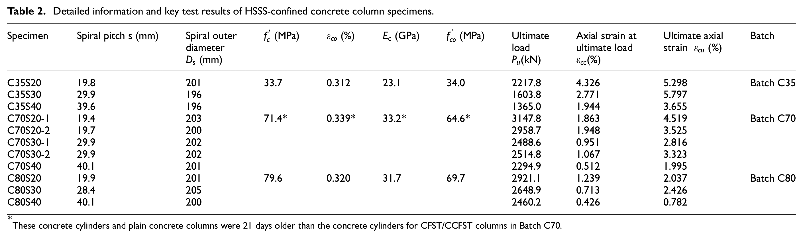
These concrete cylinders and plain concrete columns were 21 days older than the concrete cylinders for CFST/CCFST columns in Batch C70.
Material properties
The test specimens were cast in three batches with commercial ordinary Portland cement concrete of three different target unconfined concrete cylinder strengths from a local supplier. The three batches of concrete, with concrete cylinder strengths of around 35 MPa, 70 MPa, and 80 MPa, are referred to as Batch C35, Batch C70, and Batch C80, respectively (Tables 1 and 2). For each batch, three standard plain circular concrete cylinders (diameter × height = 150 mm× 300 mm) were cast and tested to determine the concrete properties according to EN 12390-3 (CEN, 2009). These concrete cylinders were tested within the same week as that of testing the corresponding CFST/CCFST or HSSS-confined concrete columns. For both Batch C35 and Batch C80, the HSSS-confined concrete columns were also tested within the same week as that of testing the corresponding CFST/CCFST columns. However, for Batch C70, the HSSS-confined concrete columns were tested at least 21 days later than testing the corresponding CFST/CCFST columns; therefore, another three concrete cylinders were tested to determine the unconfined concrete properties in the HSSS-confined concrete columns of Batch C70 (Table 2). The unconfined concrete strength
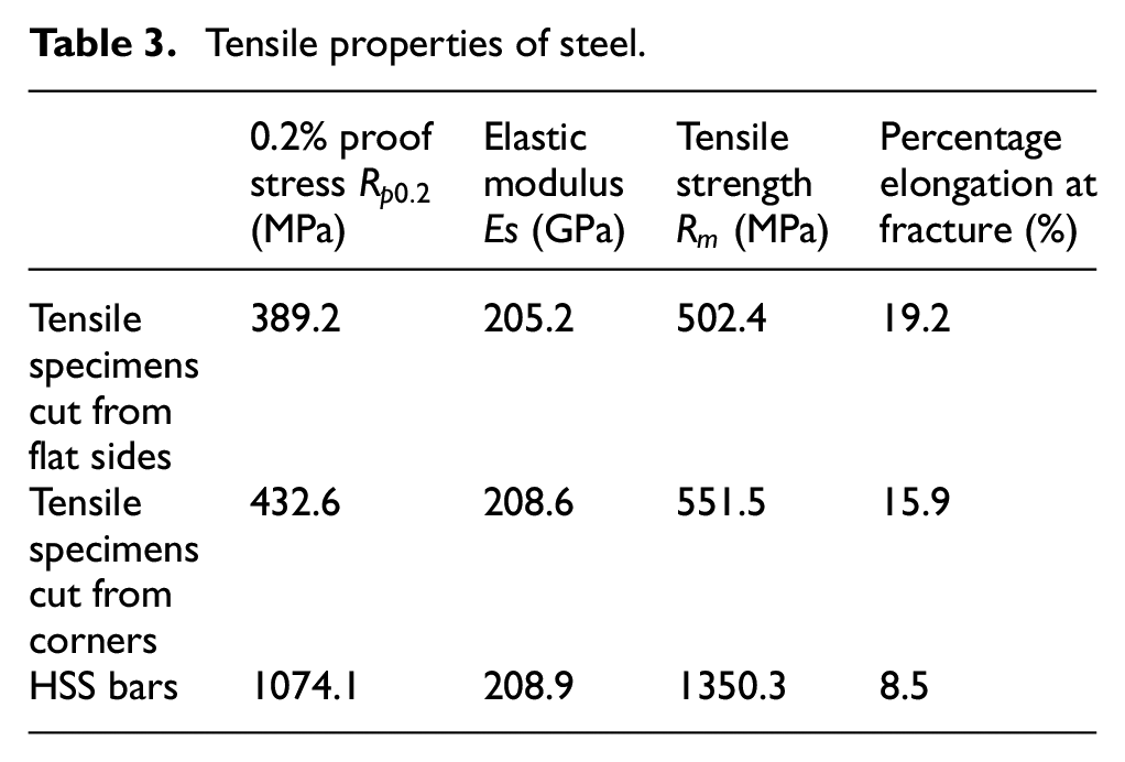
Tensile tests on “dog-bone” coupons were conducted to obtain the material properties of the steel tubes in accordance with EN 6892-1 (CEN, 2016) (Figure 2). These tensile test coupons were cut longitudinally from the mid-width positions of flat sides and the midpoints of corners of a single square steel tube. The steel coupons from the flat sides had a rectangular cross-section, while those from the rounded corners had a small circular cross-section (Figure 2). The effects of different shapes and/or sizes of steel coupons on the obtained tensile stress-strain curve of steel are believed to be limited (Liu, 2017). Three tensile coupons cut from a straight steel bar (before being cold bent to form a steel spiral) provided by the supplier were tested to obtain the material properties of the steel spirals in accordance with EN 6892-1 (CEN, 2016). The tensile stress-strain curves of the steel tube coupons and HSS coupons are shown in Figure 3. It can be seen that the stress-strain curves of both steel tubes and HSS spirals exhibit no yield plateau. As the square tubes in the present study were cold-formed from circular tubes, the forming process is believed to have led to the disappearance of the yield plateau. For such a stress-strain curve, the proof stress corresponding to a 0.2% plastic strain [i.e. 0.2% offset strain as per EN 6892-1 (CEN, 2016)] is commonly taken as the nominal yield stress (also referred to as the 0.2% proof stress) (e.g. Ahmad and Shah, 1982; Li et al., 2001). The average 0.2% proof stress (Rp0.2), the tensile strength (Rm), the elastic modulus (
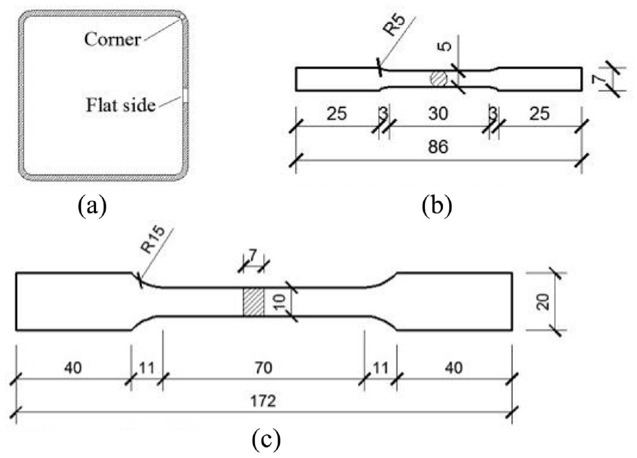
Steel coupons cut from a steel tube and coupon dimensions (in millimeter): (a) steel tube, (b) coupons from corners, and (c) coupons from flat sides.
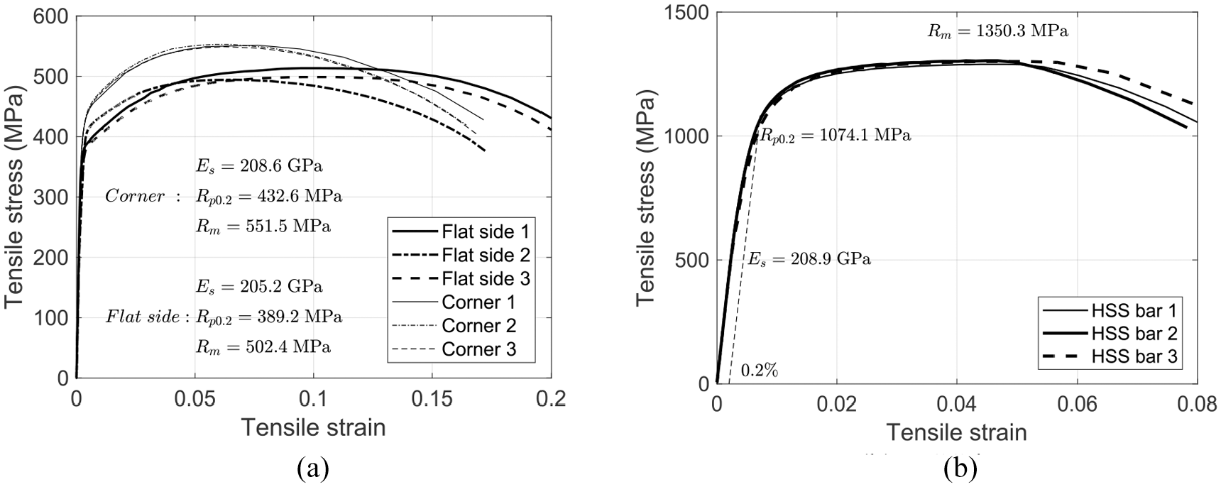
Tensile stress-strain curves: (a) steel tube coupons and (b) HSS bars.
Tensile properties of steel.
Preparation of column specimens
The square steel tube was first cut to the required length and then welded onto a 25-mm-thick steel plate at the bottom to form a mold. For specimens without a steel tube, a PVC tube was fixed onto a water-proof wooden plate. An HSS spiral installed with strain gauges was next placed into the mold and the concrete was then poured in. A handy mechanical vibrator was inserted into the concrete to ensure the compaction of the concrete. After curing for more than 28 days, the top surfaces of the CFST/CCFST column specimens were capped with flowable high-strength plaster. When the plaster had hardened, another 25-mm-thick steel plate was welded on the top end of the steel tube. Two small holes were drilled through the top steel plate to allow the strain gauge wires to come out. For the circular HSSS-confined concrete columns, a 50-mm-wide CFRP strip was wrapped at each end of the column to prevent premature local failure there; both ends were capped with high-strength plaster to ensure uniform loading from the loading platens.
Test setup and Instrumentation
For all specimens with a steel tube, four linear variable displacement transducers (LVDTs) were mounted on the square steel tube covering a mid-height range of 300 mm (referred to as mid-height LVDTs) and another four LVDTs were installed at the four corners between the two end steel plates to measure the overall shortenings (referred to as full-height LVDTs) (Figure 4). In addition, four bi-axial strain gauges with a gauge length of 3 mm were attached at the mid-width locations of external flat surfaces of a square steel tube at the mid-height to measure both axial and hoop strains. For each HSSS-confined concrete specimen, four mid-height LVDTs and four full-height LDVTs were also used to measure the axial shortenings. In addition, four axial strain gauges with a gauge length of 100 mm and two hoop strain gauges with a gauge length of 50 mm were installed at 90° apart and 180° apart, respectively, on the concrete surface at the column mid-height (Figure 4(b)). For each HSS spiral, eight strain gauges with a gauge length of 2 mm were installed at 90° apart on the inner edge of the spiral at the two levels closest to the column mid-height (Figure 4(b)). All the compression tests were conducted with a displacement control rate of 0.45 mm/min, with the test data being recorded simultaneously by a data logger.
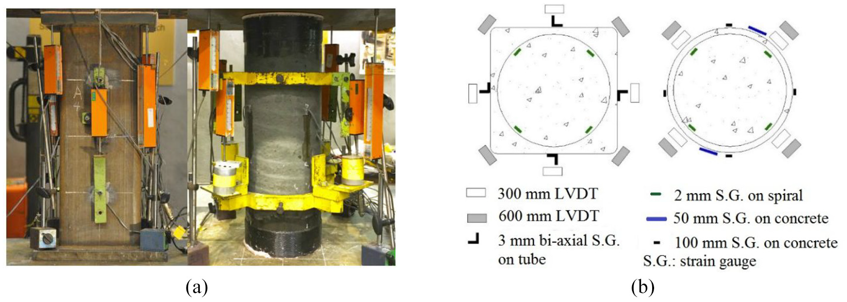
Test setup and instrumentation: (a) test set-up and (b) strain gauge and LVDT layouts.
Test results and discussions
Failure process
HSSS-confined concrete columns
Figure 5 shows the failure modes of all the HSSS-confined concrete columns tested in the study and one of the plain concrete columns of Batch C70. All the HSSS-confined concrete columns failed by the rupture of the steel spiral near the column mid-height. During the loading process, small cracks first appeared near the column mid-height and then merged to form several major cracks as the axial load increased. The concrete between two adjacent spiral turns was squeezed out and gradually spalled after the attainment of the peak load. No diagonal shear cracks were observed in the HSSS-confined concrete columns, while an obvious major shear crack occurred in the plain concrete column (Figure 5). It was also observed that the concrete of the lower part, which was originally the upper part when the columns were in the casting position, was more susceptible to spalling. As the columns were cast vertically, the original upper region was probably slightly weaker than the lower region due to the effect of casting position.
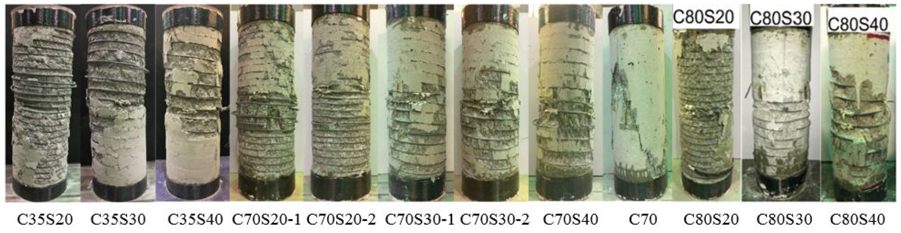
HSSS-confined concrete column specimens after test.
CCFST and CFST columns
All CCFST columns experienced large axial deformation and outward local buckling of the steel tube as shown in Figure 6(a). The failure processes of all CCFST columns were similar. As an example, Figure 7(a) shows the photos of specimen CS70S30-1 at five different loading/deformation states (i.e. yielding when the slope of the axial load-axial displacement curve reduces to 10% of the initial slope, peak load, first instance of rupture of the steel spiral, second instance of rupture of the steel spiral and final state), and the axial load-axial displacement curve of the specimen is shown in Figure 7(b). It was observed that no obvious outward local buckling of the steel tube occurred before the peak axial load (Figure 7(a)). After the peak axial load, outward local buckling of the steel tube near the column mid-height was observed. The axial load remained at a high level for a long time after the peak axial load, indicating a ductile process of failure. As the axial displacement increased to about 15–18 mm, the HSS spiral of the column started to rupture sequentially accompanied by drops in the axial load (Figure 7(b)). Even after the first instance of spiral rupture, the column could still resist a large axial load. After several instances of spiral rupture, the axial load reduced to a minimum load, after which the axial load started to increase slightly (Figure 7(b)). The loading process was terminated manually when the column experienced a sufficiently large axial displacement. Figure 6(a) shows the final states of all the CCFST columns tested in the study. It can be seen that the locations of local buckling of steel tube in the test CCFST columns were not identical. The locations of steel tube local buckling were greatly influenced by the geometric imperfections of the steel tubes as revealed in Wang (2020). In Wang (2020), a CCFST column, which is not reported in the present paper, was cut open, and it was found that the rupture of the HSS spiral occurred near the locations of local buckling of the steel tube.
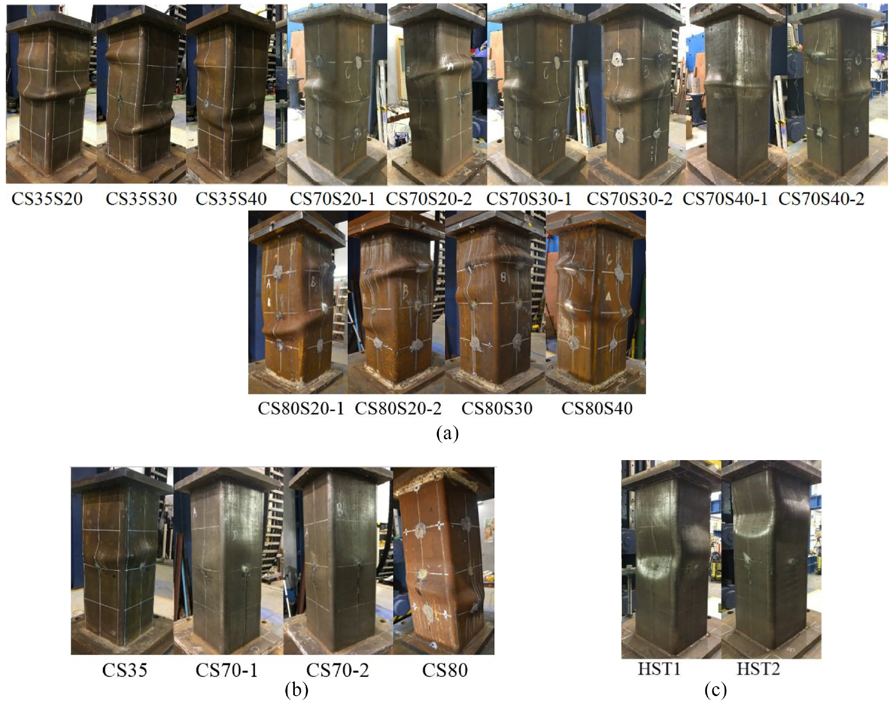
Square column specimens after test: (a) CCFST columns, (b) CFST columns, and (c) HST columns.
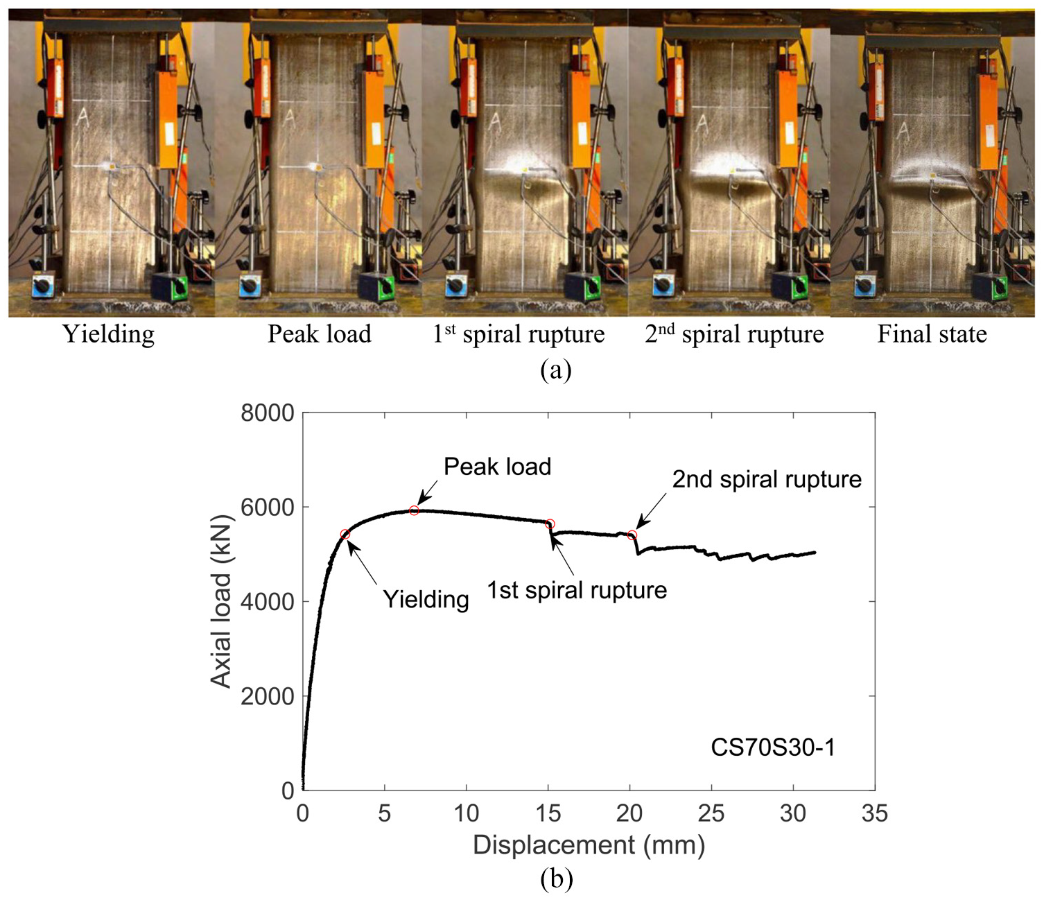
Failure process of specimen CS70S30-1: (a) failure process and (b) axial load-axial displacement curve.
The final states of all the CFST columns tested in the study are shown in Figure 6(b). Obvious outward local buckling of the steel tube was also observed. However, local buckling of the steel tube in these columns occurred at an axial displacement (about 3 mm) much smaller than those of the corresponding CCFST columns, with the buckling deformations at the final state in the former being much smaller than those in the latter. In addition, the axial load of CFST columns dropped sharply after the peak axial load, indicating a much more brittle failure process than that of CCFST columns. The two HST columns (HST1 and HST2) experienced both inward and outward local buckling deformations, as shown in Figure 6(c).
Axial load-axial strain curves
HSSS-confined concrete columns
The axial load-axial strain curves of the HSSS-confined concrete columns are shown in Figure 8, where the axial strains were averaged from the readings of the four mid-height LVDTs. The red cross symbol (×) on each curve indicates the point when the average tensile strain of the spiral near the column mid-height reached its 0.2% proof stress. This occurred before the peak load for most of the specimens except for C70S40 and C80S40. It is also evident that the presence of an HSS spiral significantly enhances both the ductility and the ultimate load of the concrete column, with the enhancement being greater for a smaller spiral pitch. Figure 8 also shows that the axial load-axial strain curve of HSSS-confined concrete generally consists of three segments: a linear first portion from the origin, a curved second portion connecting the first portion to the peak load point, and a post-peak descending final portion. The second portions of Batch C35 specimens (referred to as C35 specimens for brevity) (Figure 8(a)) seem to be much longer than those of C70 and C80 specimens (Figures 8(b) and (c)), leading to much larger axial strains at peak load in the former. As the spiral pitch decreases, the post-peak descending portion becomes much flatter (i.e. the axial load decreases much more gradually). It should be noted that the significant difference in response between the two nominally identical specimens C70S20-1 and C70S20-2 was caused by a significant difference in the spiral outer diameters of the two specimens (see Table 2).
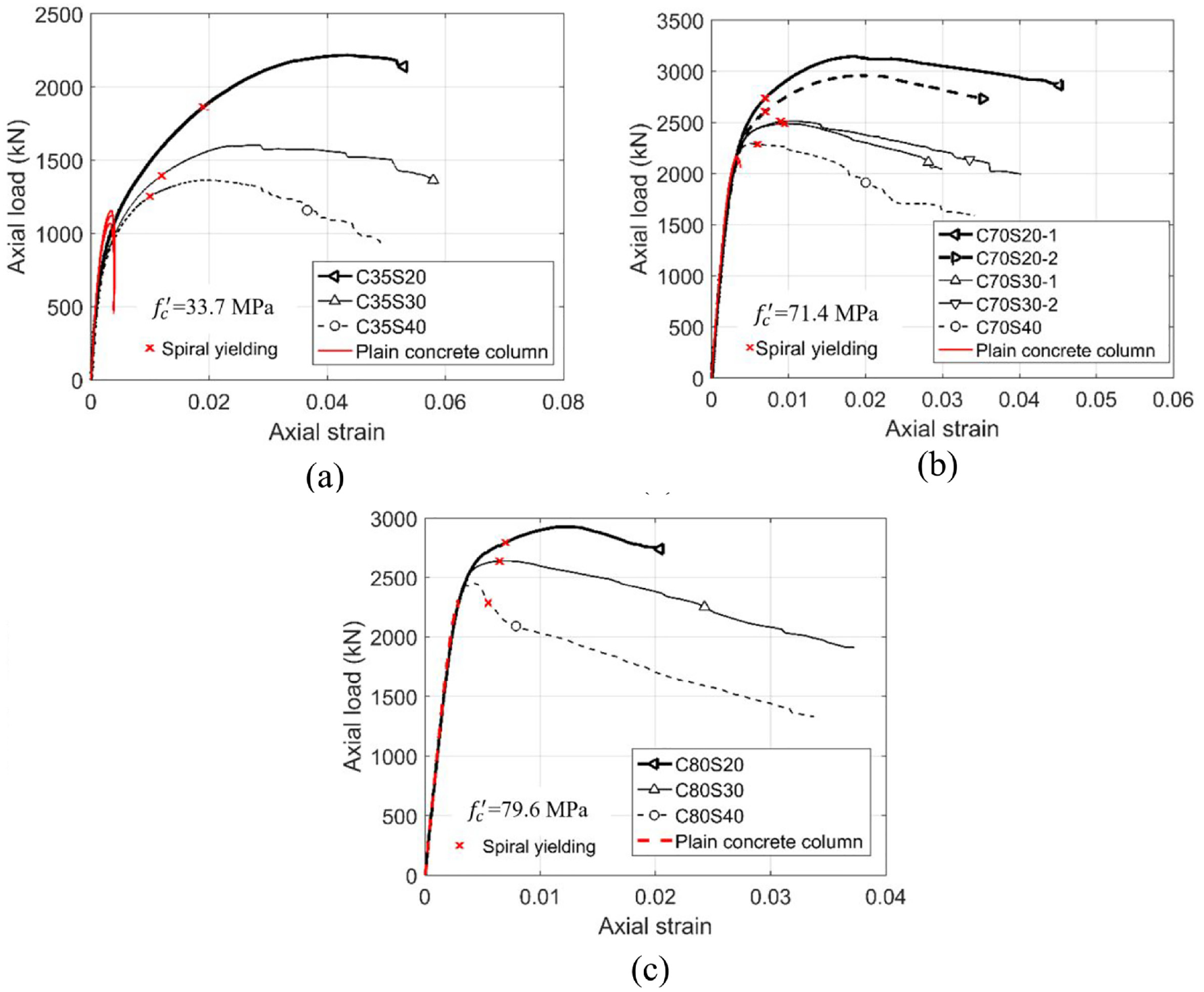
Axial load-axial strain curves of HSSS-confined concrete columns: (a) C35 specimens, (b) C70 specimens, and (c) C80 specimens.
CCFST and CFST columns
Figure 9 shows the axial load-axial strain curves of CCFST and CFST columns, in which the axial strains were averaged from the readings of the four full-height LVDTs. The readings of the mid-height LVDTs were heavily influenced by the local buckling deformation of the steel tube and were thus not used in the subsequent discussions (Wang, 2020). It is obvious that the curves of CCFST columns are much higher and longer than those of the corresponding CFST columns. For the C70 and C80 CCFST columns, the axial load-axial strain curves are similar in shape to those of the corresponding HSSS-confined concrete columns, which is not the case for the C35 columns (Figure 9(a)). As the spiral pitch decreases, the axial load-axial strain curve of a C35 CCFST column changes from a descending-type curve (the axial load decreases after the peak load) to an ascending-type curve (the axial load increases continuously) as can be seen from Figure 10(a). It is also seen that the difference in peak load between specimens CS35S30 and CS35S40 is negligible. This is not beyond expectation because the enhancement in ultimate stress as the spiral pitch decreased from 40 mm to 30 mm was small for HSSS-confined concrete as shown in Figure 8(a). Figure 9 also shows that the axial load-axial strain curves of two nominally identical specimens are not exactly the same (e.g. CS80S20-1 vs CS80S20-2). This is also not beyond expectation because the two nominally identical specimens were not perfectly identical. It should be noted that most of the strain gauges installed on the steel spirals in the CCFST columns had been damaged before the column peak axial stress was reached; therefore, the spiral strains are not reported herein.
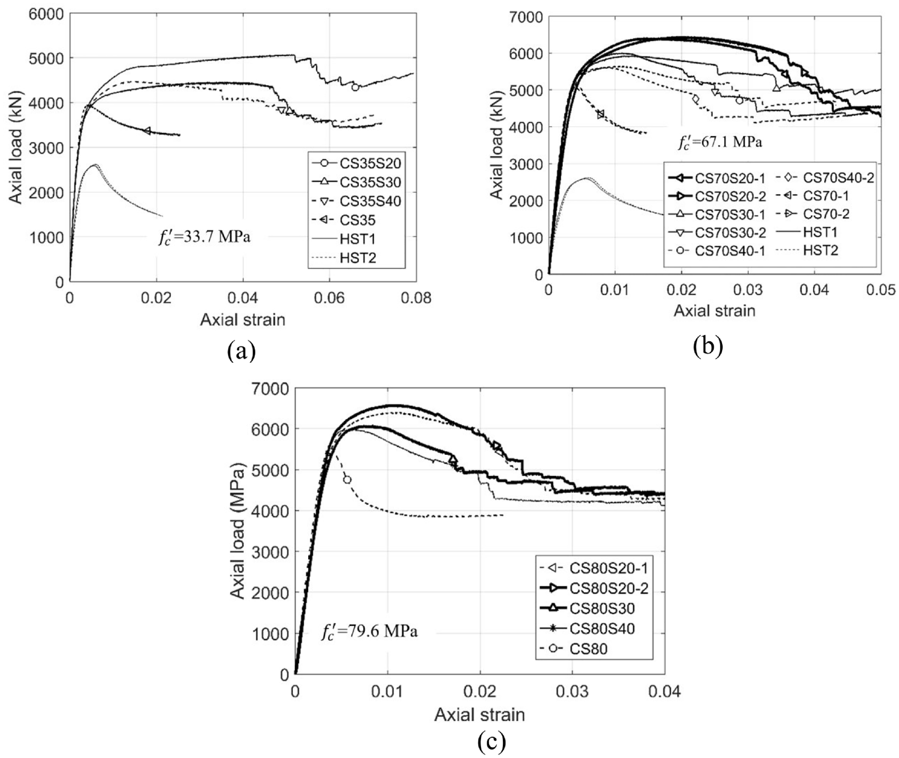
Axial load-axial strain curves of CCFST columns: (a) C35 specimens, (b) C70 specimens, and (c) C80 specimens.
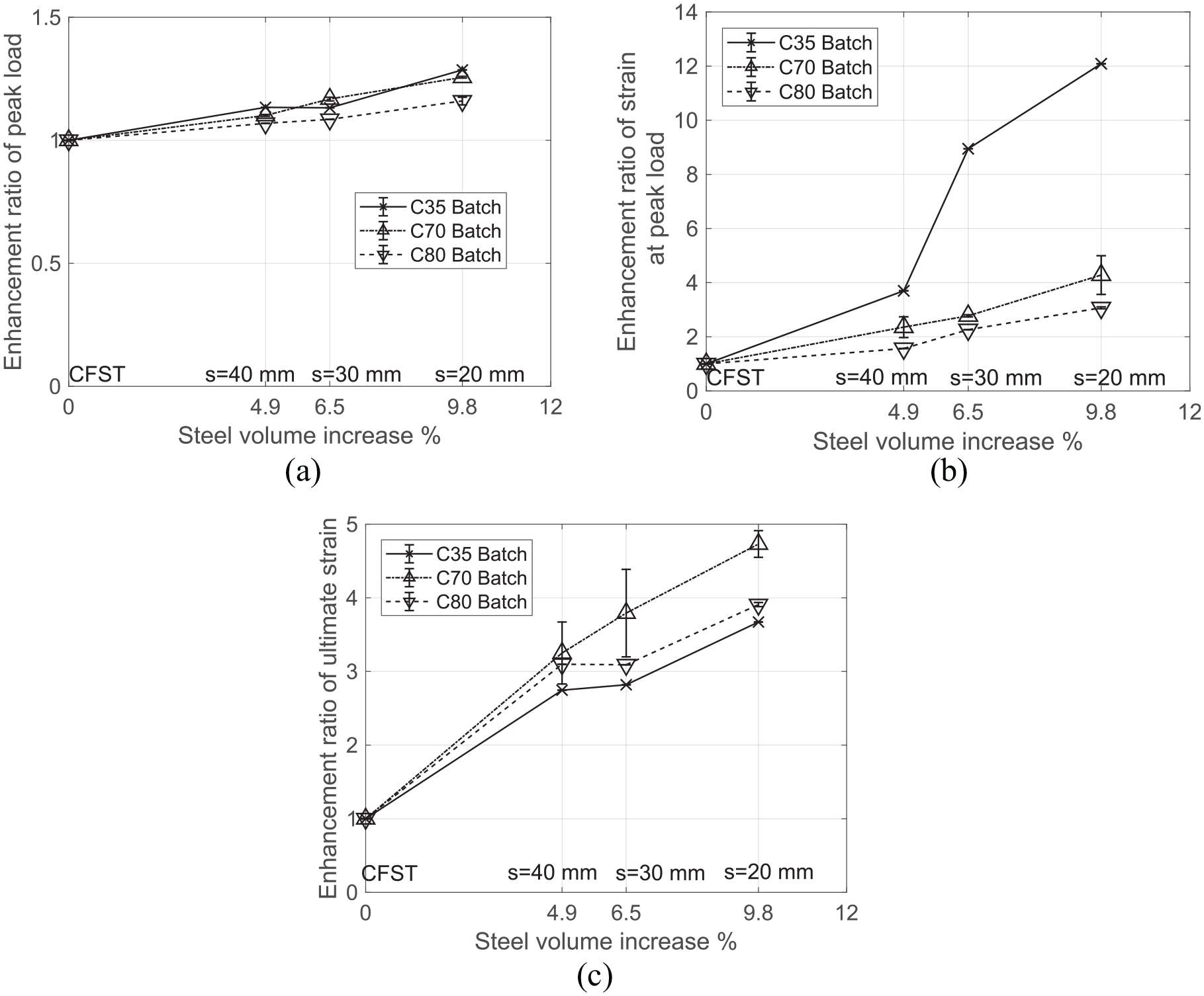
Enhancement ratio versus HSS spiral volume ratio: (a) ultimate load, (b) axial strain at ultimate load, and (c) ultimate axial strain.
Final condition
The final condition of HSSS-confined concrete columns is defined as the point when the post-peak axial load reduction has reached 15% or when the spiral has ruptured, whichever occurs first. Among the 11 HSSS-confined concrete columns, five of them (C35S20, C35S30, C70S20-1/2 and C80S20) experienced spiral rupture before the axial load had dropped by 15% (Figure 8). All the CCFST columns could resist large axial loads even after the spiral had ruptured and the final condition of all CCFST columns is defined as the point when the axial load has dropped by 15%. The final condition point of each test column is indicated by an appropriate symbol on the descending branch of the axial load-axial strain curve in Figures 8 and 9. Tables 1 and 2 summarize the ultimate axial loads (i.e. peak axial loads) (
Ductility index
The values of the strain ductility index, which is defined as the ratio between the ultimate axial strain and the yield axial strain, of all the CFST and CCFST columns are listed in Table 1. As mentioned earlier, the ultimate axial strain is taken as the axial strain when the axial load has reduced by 15% from its peak value for CFST/CCFST columns. However, a consensus on the definition of the yield strain (or yield displacement) of CFST columns does not exist. Of the various methods used to define the yield axial strain of CFST columns, the equal energy method is among the most commonly used methods, in which the yield strain is taken as the elastic limit of an equivalent elastic-perfectly plastic curve, with the equivalent yield load being equal to the actual ultimate load of the structure and the area under this equivalent curve being equal to that of the actual load-strain curve before the attainment of the ultimate load (e.g. Mahin and Bertero, 1976; Wu et al., 2006; Teng et al., 2016). This equal energy method was originally proposed for conventional RC members which generally have a descending-type load-strain curve (Park, 1988). As the actual ultimate load is taken as the equivalent yield load, the yield strain is overestimated for an ascending-type load-strain curve, especially when the post-yield ascending branch is relatively long.
Some other researchers have defined the yield point of a CFST column as its ultimate load point (Han, 2002; Zhu and Chan, 2018), which is obviously unreasonable for specimens with an ascending-type load-strain curve. Feng et al. (2015, 2017) has recently proposed that the yield point should be defined as the point of the load-strain curve where the slope is equal to that of a secant line connecting the origin to the ultimate load point. It is obvious that the so-obtained yield strain depends on the ultimate load, rendering the method inconsistent for ascending-type and descending-type load-strain curves. Hu et al. (2020a) defined the yield strain as 4/3 times the strain at 75% of the ultimate load on the ascending branch of the load-strain curve, which is also unreasonable for specimens with an ascending-type load-strain curve. To overcome the difficulties associated with the existing definitions of the yield strain, the yield point of the load-strain curve of a CFST/CCFST column is defined herein as the point where the tangent slope has decreased to 10% of the initial slope of the curve. With this definition, the yield point is not affected by the ultimate load, so the method leads to consistent results for both ascending-type and descending-type load-strain curves. It should be noted that while the present definition of yield point has worked well for the purpose of comparing ductility levels for the CFST/CCFST columns tested in the present study, it is not claimed as a universally valid definition; indeed, its suitability for application in other situations should be separately examined each time.
Figure 11 shows the strain ductility index versus the HSS spiral volume ratio for all the CCFST and CFST columns. In determining the yield point, the two points with axial loads of 500 kN and 1500 kN on the axial load-axial strain curve were used to obtain the approximate initial slope of the curve. Figure 11 clearly shows that the presence of HSS spiral reinforcement in CFST columns results in a substantial increase in the ductility index. Compared with the corresponding CFST columns, the HSS spiral volume ratio of specimens CS35S40, CS70S40, and CS80S40 with a spiral pitch of 40 mm was only 4.9% (i.e. the volume of steel consumed by the specimens increased by only 4.9%), but the average strain ductility index values increased by 138%, 177%, and 161%, respectively, illustrating the great efficiency of the HSS spiral reinforcement and the proposed column form. Figure 11 also shows that the ductility index values of CFST and CCFST columns with a lower concrete strength are larger than those of the columns with a higher concrete strength.
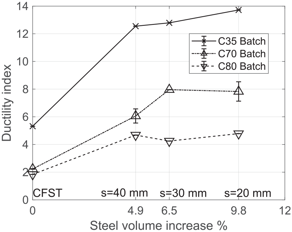
Ductility index versus HSS spiral volume ratio for CCFST and CFST columns.
Analysis and discussions of experiment results
Stress-strain behavior of HSSS-confined concrete
Existing stress-strain models for HSS-confined concrete
The axial stress-axial strain behavior of NSS-confined concrete has been extensively studied, leading to many axial stress-axial strain models (referred to simply as stress-strain models) for such concrete, with the most-cited one being Mander et al.’s (1988) model. However, it has been found that these models fail to predict the stress-strain behavior of HSS-confined concrete (in the form of HSS hoop or spiral confined concrete) with enough accuracy (Assa et al., 2001). Compared with the stress-strain models for NSS-confined concrete, only a small number of stress-strain models have been proposed for HSS-confined concrete (e.g. Akiyama et al., 2010; Assa et al., 2001; Kim et al., 2017; Li et al., 2001; Razvi and Saatcioglu, 1999). Some of these models were modified from Mander et al.’s (1988) model for application to both NSS- and HSS-confined concretes. In this section, Mander et al.’s (1988) model together with three existing stress-strain models for HSS-confined concrete are briefly reviewed (Akiyama et al., 2010; Li et al., 2001; Razvi and Saatcioglu, 1999), followed by a comparison between their predictions and the test results of the HSSS-confined concrete columns from the present study. These models are classified as design-oriented stress-strain models using the terminology of the existing literature on FRP-confined concrete (Teng and Lam, 2004) as they employ explicit simple algebraic expressions to describe the stress-strain curve. Other models which employ a complex iterative process to generate the stress-strain curve (e.g. Kim et al., 2017) are not included in the discussions below. In making predictions using all the models, the experimental values of elastic modulus and axial strain at peak stress of unconfined concrete were used.
In Mander et al.’s (1988) model, the following equations are used to describe the stress-strain curve of NSS-confined concrete:
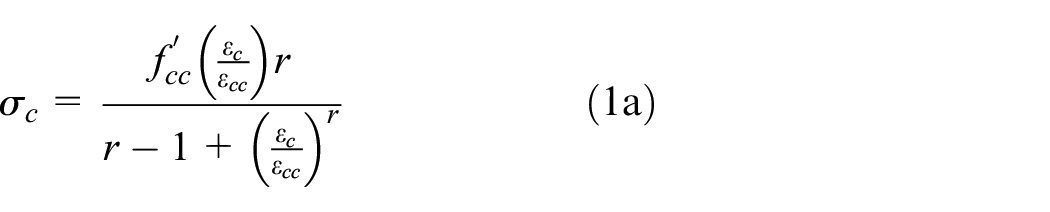
where

where
where
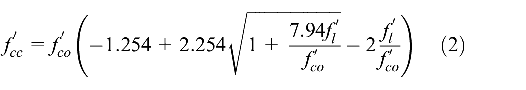
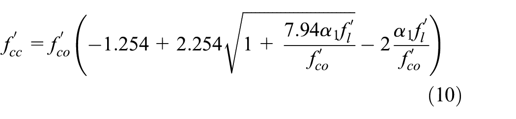
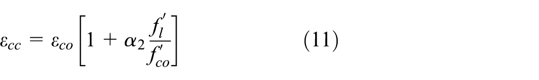
Razvi and Saatcioglu’s (1999) model directly employs the expression of equation (1) of Mander et al.’s (1988) model for the ascending segment of the stress-strain curve but uses a linear curve for the descending segment after the peak stress. The following equations, which are different from those of Mander et al.’s (1988) model, are used to calculate the peak stress and the corresponding strain:
where
where
where
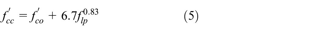
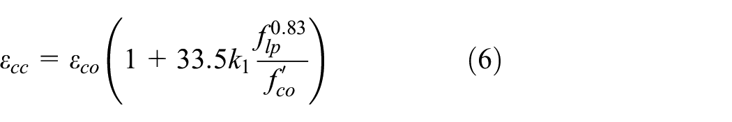
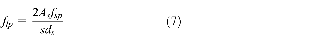
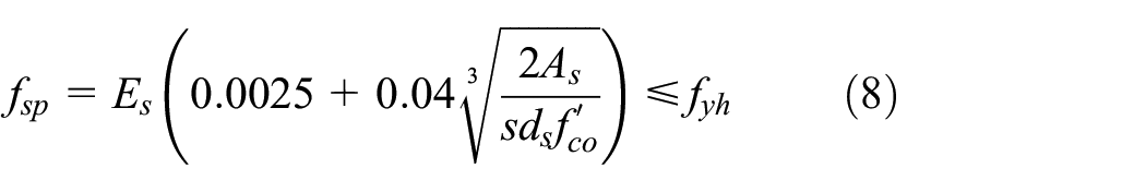
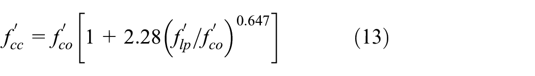
Li et al.’s (2001) model consists of three segments: a parabolic first segment connecting the origin to the point of unconfined concrete strength (
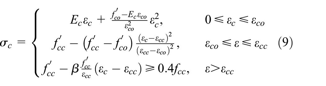
where
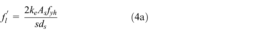
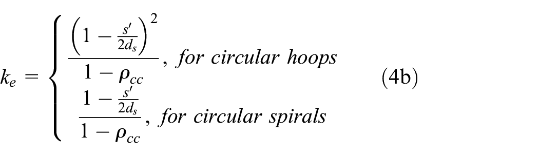
Akiyama et al.’s (2010) model consists of a nonlinear segment for the ascending branch of the stress-strain curve before the peak stress and an exponential segment for the descending branch:
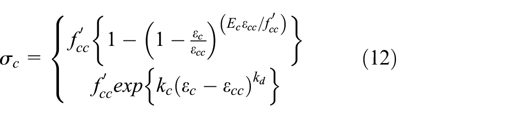
where
where
Similar to Razvi and Saatcioglu’s (1999) model, Akiyama et al.’s (2010) model also assumes that the peak stress of HSS-confined concrete may occur before the transverse steel yields, but a different equation was proposed to calculate the stress of the steel hoops/spirals at the peak stress of concrete,
Comparison
In Figure 12, the predictions from the four stress-strain models reviewed above are compared with the experimental results for the nine HSSS-confined concrete columns tested in the present study. The experimental axial stresses were obtained from the axial loads resisted by the column divided by the concrete area enclosed by the centerline of the spiral. The load resisted by the concrete cover was ignored due to its negligible thickness. It is evident from Figure 12 that Mander et al.’s (1988) model, which was developed for NSS-confined concrete, significantly overestimates the axial stress of HSSS-confined concrete for all the test columns. It should be noted that the 0.2% proof stress was taken as the yield stress (
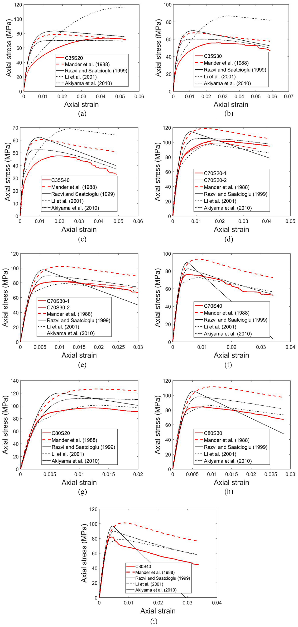
Performance of existing stress-strain models for HSS-confined concrete: (a) C35S20, (b) C35S30, (c) C35S40, (d) C70S20, (e) C70S30, (f) C70S40, (g) C80S20, (h) C80S30, and (i) C80S40.
Axial load-axial strain behavior of CCFST columns
A CCFST column section can be divided into three components: the outer square steel tube, the inner HSSS-confined concrete core and the sandwiched concrete between the two (Figure 1(a)). In Figure 13, the axial load-axial strain curves of the CCFST columns are shown against four other axial load-axial strain curves: (1) a curve for a representative HST column test (HST test); (2) a curve for the corresponding HSSS-confined concrete column; (3) a curve for the sandwiched concrete (SC); (4) the sum of stresses from (1), (2), and (3). As the tests on HST columns were terminated at an axial strain smaller than the ultimate axial strains of CCFST columns, the curve of the HST column beyond this strain was extrapolated from the experimental curve via an exponential extension to enable direct comparison. The behavior of the sandwiched concrete was assumed to be the same as that of the infilled concrete in the corresponding CFST column (namely, the axial stress of the sandwiched concrete at a given axial strain is equal to the average axial stress of the infilled concrete in the CFST column). The axial load carried by the concrete in a CFST column was obtained by subtracting the load carried by the steel tube from the total load carried by the CFST column. The axial load carried by the steel tube in the CFST column at a given axial strain was obtained from the axial load-axial strain curve of the HST column. The use of the test results of the HST column, however, may underestimate the axial load carried by the steel tube in a CFST/CCFST column, as the local buckling of the steel tube can be delayed in the latter due to the restraint provided by the infilled concrete (Sakino et al., 2004). On the other hand, the existence of hoop tensile stresses in the steel tube in a CFST/CCFST column (when the concrete has dilated sufficiently) leads to a decrease in the axial load capacity of the steel tube compared with that of an HST (i.e. effect of the biaxial stress state).
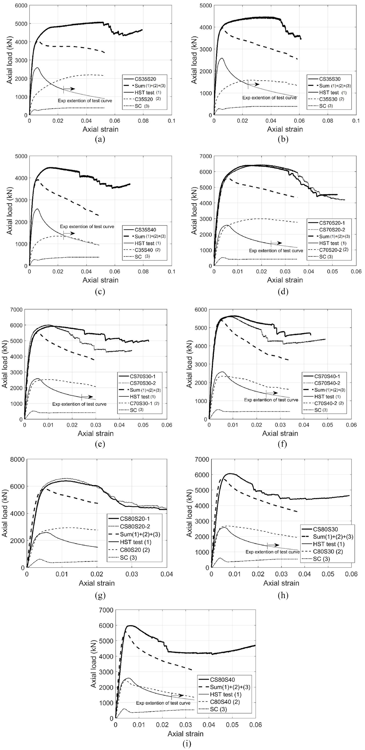
Components of axial load resistance in a CCFST column: HST curves from hollow steel tube tests: (a) CS35S20, (b) CS35S30, (c) CS35S40, (d) CS70S20, (e) CS70S30, (f) CS70S40, (g) CS80S20, (h) CS80S30, and (i) CS80S40.
It is clearly seen in Figure 13 that the curve of a CCFST column is much higher than the corresponding Sum curve during the stage of post-buckling deformation of the HST column, which indicates that the performance of a CCFST column is far superior to the expected response if no interactions were present among the steel tube, the HSSS-confined concrete core, and the sandwiched concrete. One main reason for the discrepancy between the test curve and the Sum curve is that the post-buckling load resistance of the steel tube in a CCFST column is underestimated as mentioned earlier.
To eliminate the effect of local buckling of steel tube, another axial load-axial strain curve of the steel tube, denoted by “HST coupon”, determined from the steel tensile coupon tests (see Figure 3(a)) was used, and the new set of curves is shown in Figure 14. In obtaining such an axial load-axial strain curve, one of the tensile stress-strain curves of the flat side coupons (coupon “Flat side 1” in Figure 3(a)) was taken as the representative curve for the slat flat sides, and the representative stress-strain curve for the corners (coupon “Corner 1” in Figure 3(a)) was similarly obtained. These two curves were used for the steel of the flat sides and that of the corners, respectively, for the calculation of the axial load-axial strain curve of the steel section. The same axial load-axial strain curve of the steel tube was also used to derive the axial load-axial strain curve of the sandwiched concrete. It can be seen from Figure 14 that the Sum curves are still noticeably lower than the test results of CCFST columns, except for specimens CS35S20 and CS35S30, of which the Sum curves are close to the test curves. It is worth noting that the unconfined concrete strength of the C70 HSSS-confined concrete columns was 4.3 MPa larger than that of the C70 CCFST columns, but the Sum curves using the results of the corresponding HSSS-confined concrete columns are still lower than the test results of the CCFST columns (Figures 14(d) and (f)). In addition, a finite element study (Wang, 2020) indicated that the average stress resisted by the sandwiched concrete in a CCFST column may be smaller than the average stress resisted by the infilled concrete in a corresponding CFST column. The underestimation in the axial loads of the CCFST columns by the Sum curves implies that the interaction among the three components of a CCFST column is beneficial to the ultimate load of the CCFST column, and this additional benefit is probably mainly due to the additional confinement provided by the steel tube to the HSSS-confined concrete core and the sandwiched concrete.
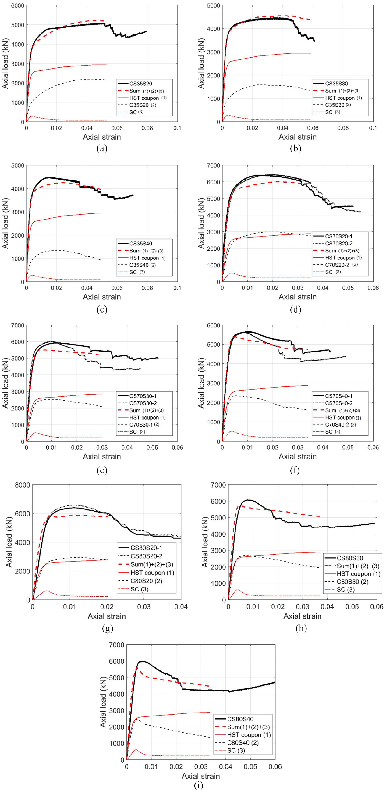
Components of axial load resistance in a CCFST column: HST curves from steel coupon tests: (a) CS35S20, (b) CS35S30, (c) CS35S40, (d) CS70S20, (e) CS70S30, (f) CS70S40, (g) CS80S20, (h) CS80S30, and (i) CS80S40.
Concluding remarks
This paper has introduced a new column form and presented the results of a series of concentric axial compression tests on such columns to demonstrate their excellent performance. The new form of columns, referred to as confined concrete-filled steel tubular (CCFST) columns, consists of a steel tube filled with concrete that is confined with high strength steel (HSS) spiral reinforcement having typically a yield stress exceeding 1000 MPa. The HSS confinement of concrete is provided to address the inadequate ductility of conventional CFST columns of non-circular sections (particularly rectangular/square sections), especially when a thin/HSS steel tube or high-strength concrete is used in such columns. Obviously, the same column form can be used for circular columns although circular CFST columns generally possess much better ductility than non-circular CFST columns and thus may not have the need for additional internal confinement.
Based on the results and discussion presented in the paper, the following conclusions can be drawn on the behavior of CCFST columns as well as that of HSSS-confined concrete columns:
The axial compression tests on HSSS-confined concrete columns indicated that they failed by the rupture of steel spiral reinforcement near the column mid-height; the presence of HSS spiral reinforcement significantly enhanced both their ductility and ultimate load, with the enhancement being greater when the spiral pitch was smaller.
All square CCFST columns experienced large axial deformation without rapid losses in the axial load resisted by the column before the loading process was terminated manually; several instances of rupture of the steel spiral reinforcement occurred following the attainment of the ultimate load, which were accompanied by corresponding small drops in the axial load.
The presence of HSS spiral reinforcement enhances both the ultimate load and the ductility of a CFST column: an HSS spiral reinforcement with a pitch of 40 mm, which increases the steel volume by only 4.9%, resulted in increases in the ultimate load by 13%, 10%, and 7% for C35, C70, and C80 CCFST columns, respectively, and the corresponding increases in the ductility index were 138%, 177%, and 161%, respectively.
None of the four existing stress-strain models for steel-confined concrete as reviewed in the paper predicts the stress-strain curves of HSS-confined concrete with sufficient accuracy, suggesting the need for the development of a more reliable stress-strain model for HSS-confined concrete in the future.
The ultimate axial load of a CCFST column is much larger than the algebraic sum of the ultimate loads of the HST, the HSSS-confined concrete core, and the sandwiched concrete between the two in an isolated state.
The ultimate axial load of a CCFST column is also larger than the algebraic sum of the three components mentioned above even if the HST is assumed to suffer no local buckling deformation, suggesting that additional benefits exist from the interaction among the three components. This also means that the axial load-axial strain curve of a CCFST column can be conservatively approximated by summing the axial load-axial strain responses of the three components. However, more research on CCFST columns over wider ranges of various parameters (e.g. spiral diameter, steel tube width-to-thickness ratio, and steel tube corner radius) is needed in the future for a more conclusive understanding of the performance of CCFST columns.
Footnotes
Declaration of conflicting interests
The author(s) declared no potential conflicts of interest with respect to the research, authorship, and/or publication of this article.
Funding
The author(s) disclosed receipt of the following financial support for the research, authorship, and/or publication of this article: The authors gratefully acknowledge the financial support received from the Research Grants Council of the Hong Kong Special Administrative Region, China through its National Natural Science Foundation of China (NSFC)/RGC Joint Research Scheme (Project No: N_PolyU520/16) and through a Hong Kong PhD Fellowship awarded to the second author.