
Abstract
A combination of coral reef sand (CRS) concrete and fibre-reinforced polymer (FRP) bars provides an effective solution to the durability deficiency in conventional RC structures. This study experimentally investigates the durability of CRS concrete beams reinforced with basalt FRP (BFRP) bars in a simulated marine environment. Flexural tests are conducted on a total of fourteen CRS concrete beams aged in a cyclic wet-dry saline solution at temperatures of 25, 40 and 55°C. The variables comprise the types of reinforcement (steel and BFRP), the aging duration and the temperature. The failure modes, capacities, deflections and crack development of the beams are analysed and discussed. The results indicate that the ultimate load of the beams exhibits no degradation after aging, whereas the failure mode of the BFRP-CRS concrete beams transition from flexure to shear, which is caused by the degradation in the mechanical properties of the stirrups. The aged BFRP-CRS concrete beams show a substantial increase of over 70% in their initial stiffness compared with the control beams (beams without aging) and a substantial decrease in their crack width after aging due to the prolonged maturation of the concrete. Furthermore, a formula for calculating the shear capacity in the existing code is modified by a partial factor equal to 2, which can predict the capacity of a CRS concrete beam reinforced with BFRP bars in a marine environment.
Keywords
Introduction
Coral reef sand (CRS) concrete emerged as an economical alternative construction material to avoid excessive transportation expenses of sand and gravel for casting concrete from inland areas (Chen et al., 2008). Although the mechanical properties of coral reefs were slightly lower than those of ordinary gravel materials (Ehlert, 1991), concrete with coral reef aggregates had a cubic compressive strength of up to 40 MPa with appropriate mix proportions (Jin, 2016). CRS was first applied to replace coarse aggregates by the United States army in the concrete structures in their military bases around the Pacific Rim (Howdyshell, 1974). However, to avoid corrosion of the steel reinforcement in concrete, a time-consuming washing process is required before concrete mixing to reduce the chloride ion content (Howdyshell, 1974), which leads to an excessive construction period. Corrosion-resistant FRP bars provide an effective solution for that issue and demonstrate their prospect as the reinforcing materials in sea-sand seawater concrete (Xiao et al., 2017; Zhang et al., 2020). However, the selection of the type of FRP bar in concrete must be considered due to the different FRPs. For example, although carbon FRP (CFRP) bars have a high strength exceeding 2000 MPa, they possess a conspicuous difference compared with concrete in their thermal expansion coefficients, which might cause uncoordinated deformation between these two types of materials at varying temperatures. Glass FRP (GFRP) bars possess a similar thermal expansivity as concrete and a relatively low cost compared with CFRP bars. GFRP reinforced concrete beams exhibits a satisfactory ductility and realises a residual deformation relatively smaller than RC beams (Zhang et al., 2019). However, the low creep rupture stress equalling 0.29fu (Yamaguchi et al., 1997) restricts their serviceability as reinforcement in a concrete structure subjected to a long-term loading. In the past two decades, newly developed basalt FRPs (BFRPs) have emerged as a cost-effective and environmentally friendly material. BFRPs show similar physical properties to GFRP in terms of their densities and thermal expansivity and has a higher strength and elastic modulus and better chemical stability than E-glass FRP (Sim et al., 2005). Moreover, the relatively high creep rupture stress of the BFRP bar equalling 0.54fu (Shi et al., 2015) ensures its capability to sustain a long-term load in a concrete structure. GFRP or BFRP bars may experience a considerable degradation in their strength with exposure to an alkaline solution (Wu et al., 2015), whereas in a dry alkaline environment such as concrete, that degradation is extremely limited. For example, Gooranorimi and Nanni (2017) reported no degradation in the GFRP bars extracted from a concrete structure after a service time of 15 years. In summary, a combination of BFRP bars and CRS concrete provides a reasonable selection for high durability, fast construction and cost savings of offshore concrete structures.
Review of existing studies
To the best of the authors’ knowledge, there are no studies on CRS concrete structures reinforced with FRP bars, but many studies on ordinary concrete or sea sand concrete structures reinforced with BFRP bars, in terms of their flexural and shear behaviours and durability, provide a sufficient reference for this study. As a fundamental parameter that reflects the bond behaviour of the BFRP bar with concrete, a bond-dependent coefficient equal to 0.76 is recommended by (Elgabbas et al., 2016b). This value is consistent with the results of another relevant study (Elgabbas et al., 2016a), which also reports that the axial stiffness of the flexural reinforcement has a substantial effect on the behaviour of concrete beams reinforced with BFRP bars. The flexural reinforcement ratio has a greater effect on reducing the deflection than increasing the loading capacity (Ovitigala et al., 2016; Zhang et al., 2015). In addition, the beam reinforced with BFRP bars failed from concrete crushing and exhibited satisfactory ductility (Elgabbas et al., 2016a). The above tests demonstrate the potential for using BFRP bars as an alternative reinforcement method in concrete members (El Refai and Abed, 2015). Experimental studies on the durability of BFRP-RC beams show that the loading capacity of beams after six, nine and twelve months are reduced by 22%, 33% and 42%, respectively, due to distinct damage at the outer layer of the BFRP bars after aging, as revealed by SEM observations (Dong et al., 2018a). Thus, the degradation in the mechanical behaviours of BFRP bars exposed to an alkaline-saline environment must be considered despite their corrosion resistance. Notably, the failure mode of sea-sand concrete beams reinforced with BFRP bars changes from concrete crushing to shear failure, and the contribution of the BFRP stirrups to the shear resistance capacity decreases after aging in 50 °C seawater for a duration that exceeds 6 months (Dong et al., 2018b). The ultimate load of concrete beams with BFRP stirrups failing in shear reached up to 90-96% of their theoretical flexural capacity, as indicated by Tomlinson and Fam (2015).
Based on the above studies, this paper presents an experimental study on the durability of BFRP-CRS concrete beams exposed to a simulated marine environment. The effects of saline corrosion on the mechanical behaviours of the beams are discussed and analysed in terms of the failure mode, loading capacity, deflection, and crack width. Furthermore, existing design provisions are calibrated for the design of BFRP-CRS concrete beams based on the experimental data.
Experimental programme
Materials
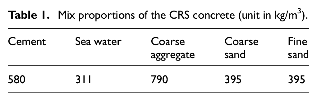
The CRS concrete was a mixture of CRS, cement and water with the optimised proportions shown in Table 1, which was obtained by a previous study by authors (Ding et al., 2019). A relatively large cement dosage and water dosage are necessary for the mixing of CRS concrete due to the large porosity of CRS. The compressive strength, which was equal to 36.5 MPa, was determined by testing three 150 × 150 × 150 mm cube blocks on the same day of flexural loading.
Mix proportions of the CRS concrete (unit in kg/m3).
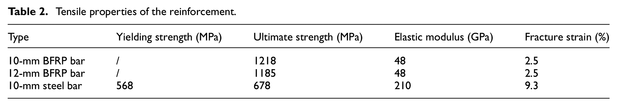
The reinforcement adopted in the flexural tests mainly included three types: 12-mm ribbed BFRP bars, 10-mm ribbed BFRP bars and 12-mm ribbed steel bars (Figure 1). The BFRP bars, with a fibre volume fraction of 65%, were manufactured using continuous basalt fibres impregnated in vinyl-ester resins through a pultrusion process. Table 2 summarises the tensile properties of the reinforcement, which were determined by testing five representative specimens according to ACI 440.3R-04 (2004) for the BFRP bars and according to GB/T 228.1-2010 (2010) for the steel bar.
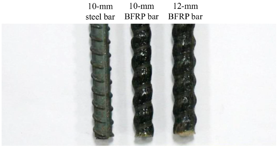
Surface configuration of the reinforcement.
Tensile properties of the reinforcement.
Specimen preparation
The length, width and height of the beams were 1350 mm, 120 mm and 200 mm, respectively. Figure 2 illustrates the details of the reinforcement. The reinforcement ratios of the beams reinforced with steel bars and BFRP bars were equal to 0.65% and 1.88%, respectively. These two reinforcement ratios produced an equivalent axial stiffness, that is, the elastic modulus multiplied by the cross-sectional area, between the tensile steel reinforcement and BFRP reinforcement. Stirrup spacings of 50 mm were adopted in the bending-shear section to avoid shear failure. Smooth steel bars with a diameter of 6 mm and ribbed BFRP bars with a diameter of 10 mm were used as stirrups in the beams reinforced with steel bars and BFRP bars, respectively. No stirrups were arranged in the constant moment zone. The beams were cast using steel formwork.
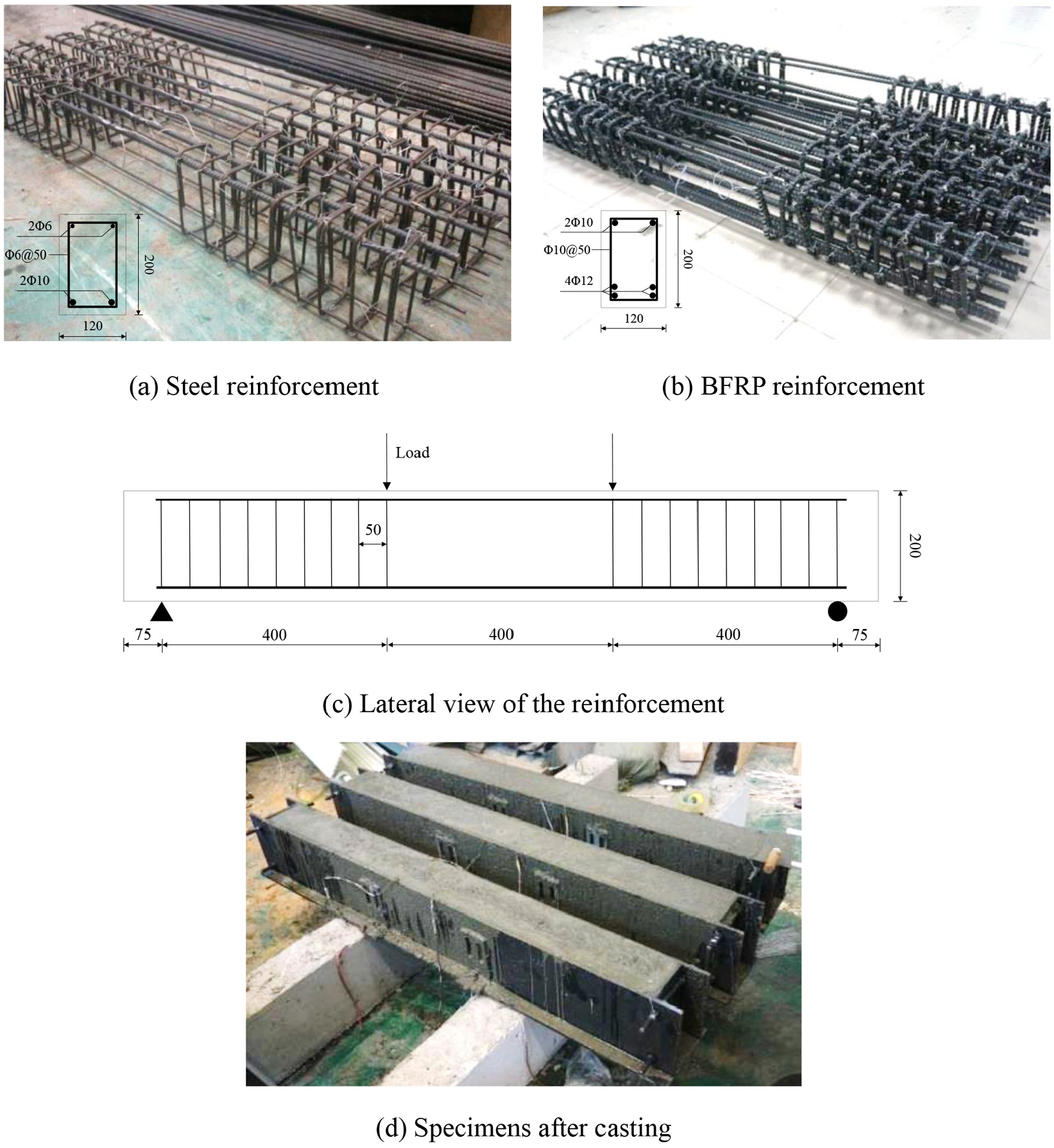
Preparation of the CRS concrete beams (units in mm).
Aging programme
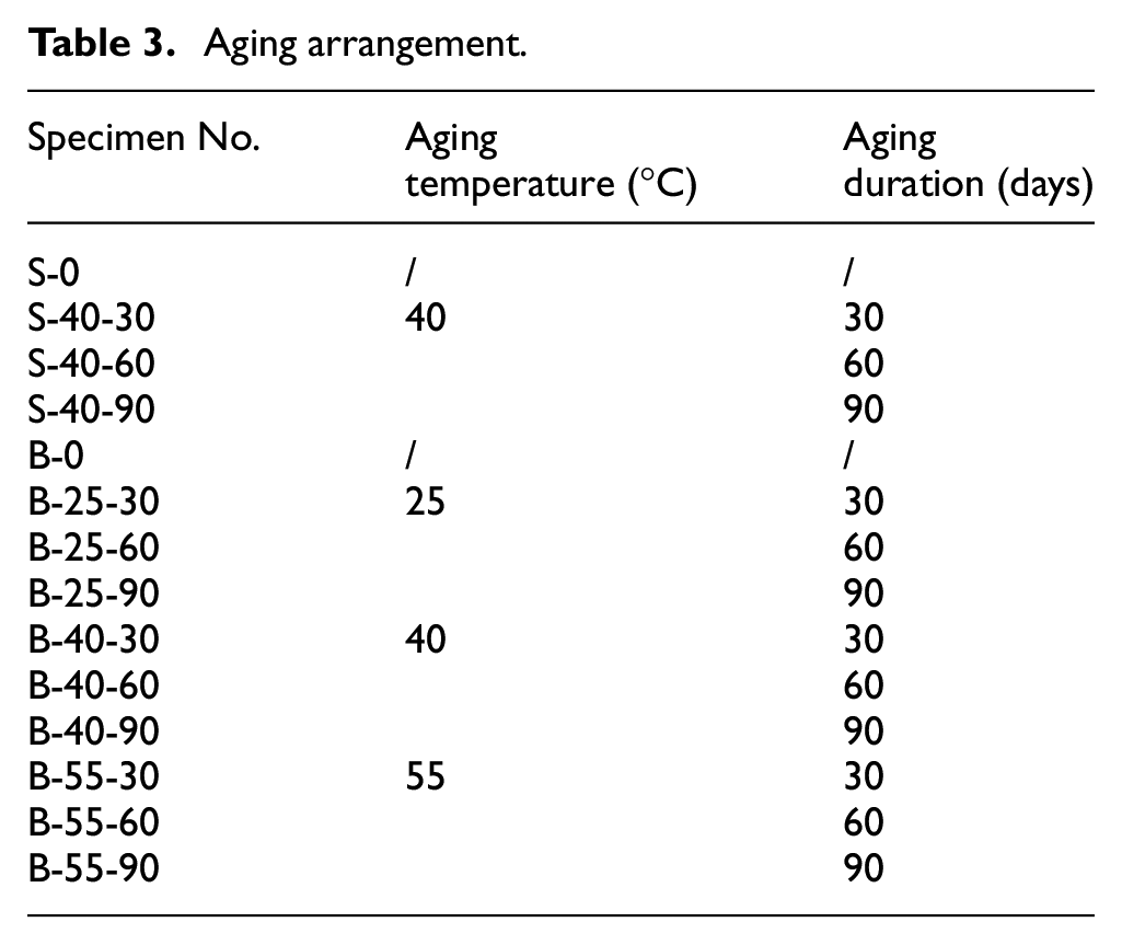
The beams were aged in a wet-dry cycling saline solution with accelerating temperature. The durations of aging were determined to be 30, 60 and 90 days. The accelerating temperatures were 25, 40 and 55°C, as shown in Table 3. The aforementioned values of temperature and duration were determined based on a previous durability study (Wu et al., 2015), which showed a considerable decrease in the strength of the BFRP bars exposed to a saline environment with the above three accelerated temperatures. The saline solution was prepared with 24.53 g/L NaCl, 5.20 g/L MgCl2, 4.09 g/L Na2SO4 and 1.16 g/L CaCl2 in deionised water according to ASTM D1141-98 (2008).
Aging arrangement.
Precrack and aging setup
A special setup was designed by the authors to simulate the cracking condition of a concrete structure at service loads, as shown in Figure 3. The bending moment occurred on the two beams by manually screwing the nut, and cracks were generated accordingly as the bending moment increased up to the cracking moment. Two load cells were adopted to monitor the load during precracking. The loads at both sides were manually applied by wrenching the nuts, up to 15 kN. After the loading was completed, cracks could be observed on the beams.
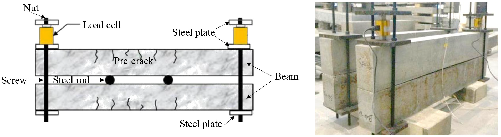
Precrack setup.
The specimens shown in Figure 3 were aged in a cyclic wet-dry saline solution. Cyclic wet-dry aging was implemented through the two aging chambers shown in Figure 4. One wet-dry cycle was 12 h to simulate tidal action. The two chambers provided a constant temperature.
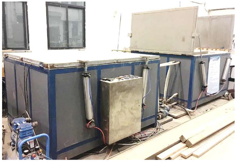
Cyclic wet-dry conditioning chambers.
Loading procedure and measurements
Flexural tests were conducted on the beams after they were aged in a wet-dry cycling saline solution using two hydraulic actuators (Figure 5). One hydraulic system was capable of providing a maximum load of 50 kN. The synchronous loading of the two actuators was realised through a stiff girder fixed with bolts. A four-point bending load was monotonically applied on the beams by 5 kN per step up to the yielding load. Subsequently, the loading rate was adjusted to 0.1 mm/s until failure.
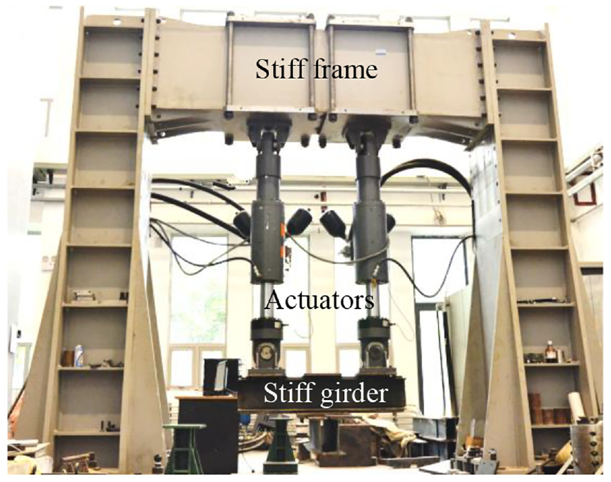
Loading setup.
The deflection was measured by five LVDTs located at the supports, the loading point and the mid-span (Figure 6). Strain gauges adhered on the tensile reinforcement were used to monitor the strain. The load data were measured by the load cell of the actuators and were recorded in the control system of the setup. The deflection and strain data were collected by a data logger with a frequency of 1 Hz. Cracks were plotted on the lateral surface of the beams, and the crack width was measured by a microscope during the test.
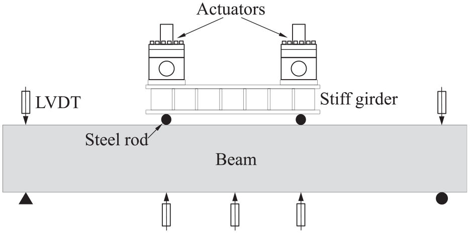
Loading and measurement of the beams.
Results and discussion
Failure modes
The results of the flexural tests are summarised in Table 4. Note that the values of the loads in Table 4 were calculated by the sum of the loads of the two actuators. The failure modes of the beams are shown in Figure 7. The aged and control beams reinforced with steel bars exhibited typical flexural failure, with concrete crushing and steel bar yielding at the mid-span. In contrast, a transformation occurred in the failure mode of beams reinforced with BFRP bars due to aging. The flexural failure mode mainly occurred for the specimens without aging, while the shear failure mode occurred for the specimens after aging in the saline solution, except for B-25-60 and B-55-90. This phenomenon could have been caused by the degradation in the mechanical properties of the stirrups, which was more serious than the degradation of the longitudinal reinforcement. The stirrup was closer to the surface of the concrete than the longitudinal reinforcement, and the bending section of the stirrup was vulnerable to erosion from the saline solution. The top BFRP longitudinal reinforcement ruptured in the bending or bending-shear failure mode.
Results of the flexural tests.
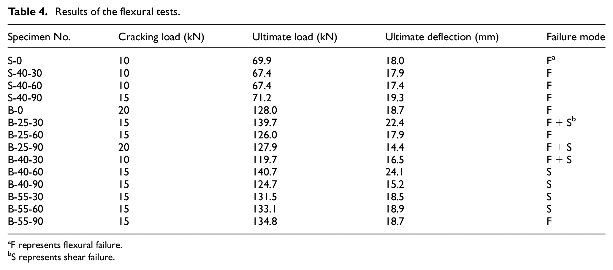
F represents flexural failure.
S represents shear failure.
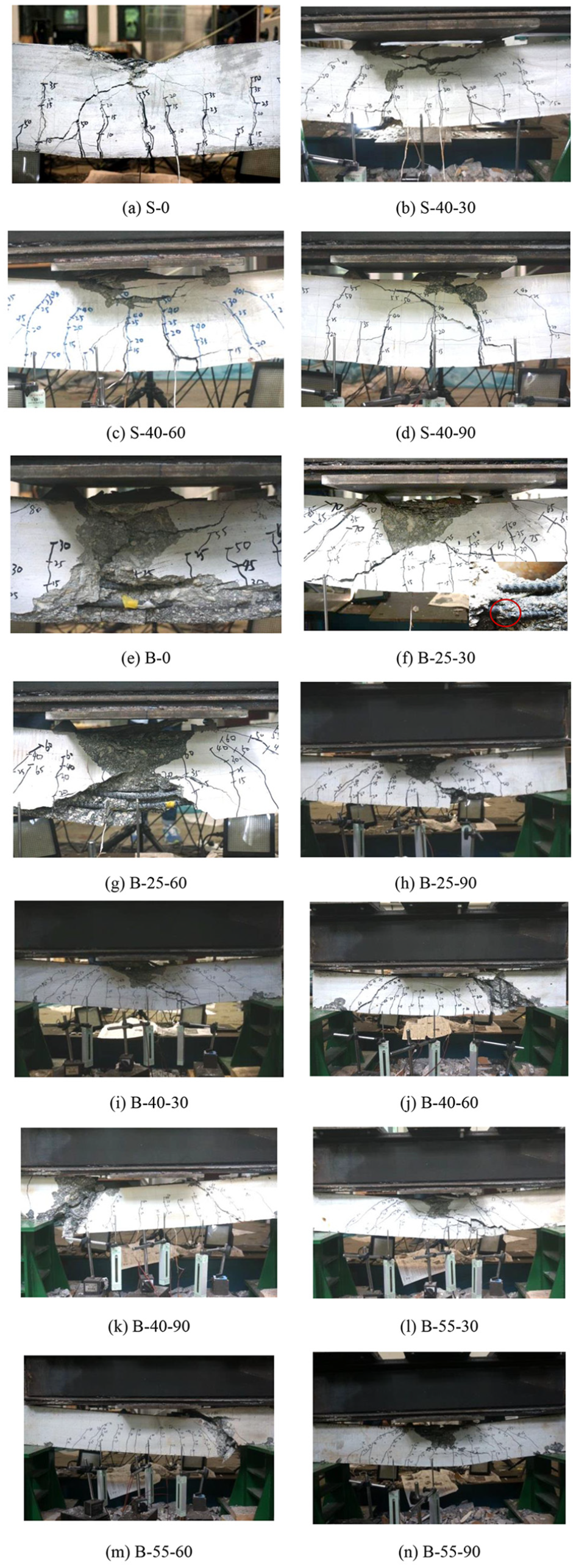
Failure modes.
Strain development in the reinforcement
Figure 8 shows the development of the strains in the BFRP and steel reinforcement in the two control beams (S-0 and B-0). The abrupt increases in the curves are attributed to the cracking of the concrete. For example, an increase of 500 με occurred in the steel reinforcement at 10 kN, which equals the cracking load of S-0. A platform occurs on that curve when the strain reaches 2000 με at the ultimate load (70 kN). Compared with that of the steel reinforcement, the load-strain curve of the BFRP reinforcement exhibits approximately linear behaviour due to the linear elasticity of the BFRP. The strain of the BFRP reinforcement at the ultimate load reaches approximately 10000 με, and the corresponding stress equals 480 MPa, which is calculated by multiplying the strain by the elastic modulus of the 12-mm-diameter BFRP bar. The formulae provided by the American and Chinese standards for the design stress of the FRP bar in a concrete beam are shown in equations (1) and (2). The values calculated by the two equations are 267 MPa and 384 MPa, respectively. Thus, Chinese standard GB 50608 has higher precision for the prediction of the stress in the FRP bars, and it is also adopted for the analysis of the loading capacity.
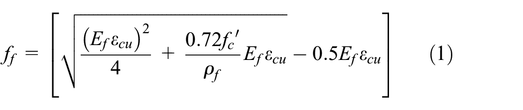
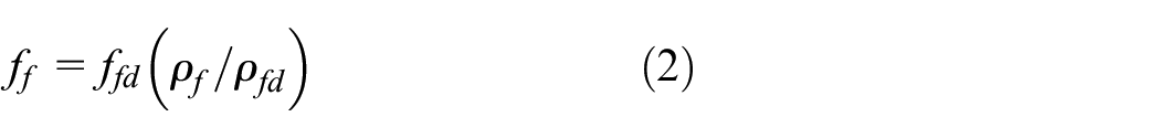
in which ff = the stress in the FRP reinforcement at the ultimate load (unit in MPa); ffd = the design value of the tensile strength of the FRP (unit in MPa), which is equal to the measured tensile strength; fc′ = the specified compressive strength of the concrete (unit in MPa), which is equal to 24.4 in this study; Ef = the elastic modulus of the FRP reinforcement (unit in MPa); εcu = the ultimate strain of the concrete, which is equal to 0.0033 in this study; ρf = the reinforcement ratio of the BFRP; and ρfb = the balanced reinforcement ratio.
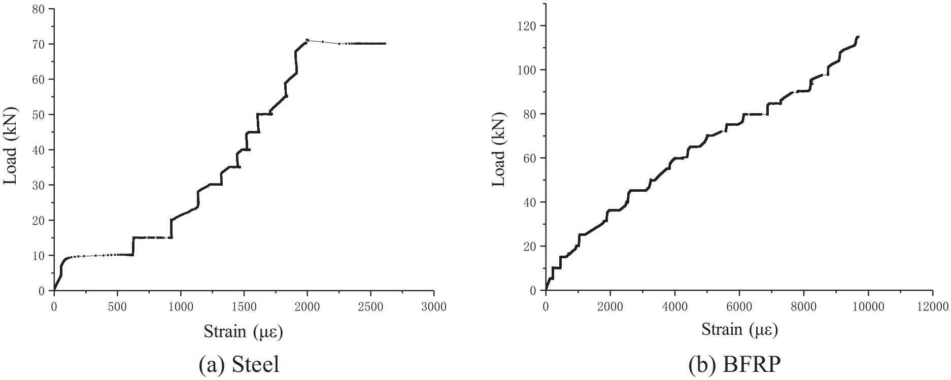
Development of the strain in the BFRP and steel reinforcement.
Loading capacity
The values of the loading capacity (Mu) can be calculated with the values of the ultimate load shown in Table 4. The loading capacity of beams reinforced with BFRP bars substantially exceeds that of beams reinforced with steel bars. This is attributed to the linear behaviour and high strength of the FRP bar. The formulae provided by GB 50608 for the design of the flexural capacity are shown in equations (3) and (4), and the calculated value is 23.1 kNm. The corresponding load for that bending moment is 116 kN, which is 9% smaller than the experimental value of B-0, validating the effectiveness of the formulae for the prediction of the flexural capacity of CRS concrete beams reinforced with BFRP bars.

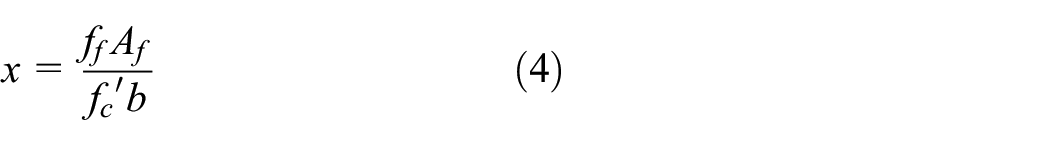
in which Mu = the flexural capacity; h0f = the effective depth of the BFRP reinforcement; x = the equivalent depth of the compressive zone of the concrete and b = the cross-sectional width.
The ultimate shear capacity, which is equal to the sum of shear resistance provided by the concrete (Vc) and shear resistance provided by the FRP stirrups (Vf), is calculated by equations (5)–(7), according to GB 50608.

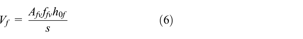

in which ft = the tensile strength of the concrete, which is considered to be 0.62(fc’)0.5 = 3.06 MPa (unit in MPa for fc’), with reference to ACI 440 in this study; k = the ratio of the depth of the compressive zone to the effective cross-sectional depth; αf = the ratio of the elastic modulus of the FRP bar to that of the concrete; Afv = the total cross-sectional area of the FRP stirrup; ffv = the tensile strength of the FRP stirrup; s = the stirrup spacing; and φbend = the reduction coefficient.
Substituting the corresponding experimental parameters into the above equations, the ultimate shear capacity of the beam is calculated to be 107.8 kN if no degradation in the mechanical properties of the FRP stirrup occurs after being aged in the saline solution. The shear capacity provided by the concrete (Vc) equals 9.5 kN, while the shear capacity provided by the stirrup (Vf) equals 98.3 kN, which indicates that the FRP stirrups provide a major contribution to the shear capacity. Thus, it is assumed that the degradation of the shear capacity of the beams is attributed to the decrease in the shear capacity of the stirrups, and the reasons are explained in terms of two aspects as discussed below. The beams aged in the saline solution exhibit a considerable variation in their loading capacities, ranging from 119.9 kN to 140.7 kN, which is mainly caused by the occurrence of the shear failure mode. The corresponding values of the shear force to the above range of the load capacity are 60.0 kN and 70.4 kN. These two values are substantially lower than the theoretical shear capacity of the beam (107.8 kN), which shows considerable effects of aging on the mechanical behaviours of the BFRP stirrups. It is noteworthy that the properties (e.g. porosity and water absorption) of CRS may differ in terms of the location where CRS was taken, which might affect the mechanical behaviours of CRS concrete and the bond behaviour between FRP bar and CRS concrete. Accordingly, the properties of CRS may influence the durability of CRS concrete beam reinforced with BFRP bars, which will be studied in future work.
Deflection responses
The load-deflection curves are shown in Figure 9. The steel-CRS concrete beams showed typical trilinear load-deflection relationships. They exhibited a slight increase in stiffness and exhibited no change in capacity compared with their counterparts without aging. The increase in the stiffness may be attributed to the enhancement of the bond behaviour of the interface, which is caused by a prolonged maturation of the concrete in a temperature-accelerated environment. The steel-CRS concrete beams had deflections similar to those of the BFRP-CRS concrete beams at 50 kN (yielding load of the steel-CRS concrete beams) due to the equivalent axial stiffness of the longitudinal reinforcement. The BFRP-CRS concrete beams exhibited a typical bilinear relationship between the load and deflection, and they showed a more substantial decrease in their stiffness than the steel-CRS beams due to the low elastic modulus of the BFRP bars compared with that of the steel bars. A substantial increase in the stiffness of the beams after aging due to the prolonged maturation of the concrete, compared with the control beam (B-0), is demonstrated in Figure 9. The rates of increase in the stiffnesses of the beams aged at 25, 40 and 55°C were equal to 73%, 70% and 79%, respectively. The load-deflection curves of the aged steel-CRS and BFRP-CRS concrete beams did not exhibit a substantial difference compared with their counterparts of control beams due to the relatively short aging duration in this study. Although there was no degradation in the bearing capacity and stiffness of the aged beams, their failure mode transformed from flexural failure into shear failure, which was mentioned in Section 4.1.
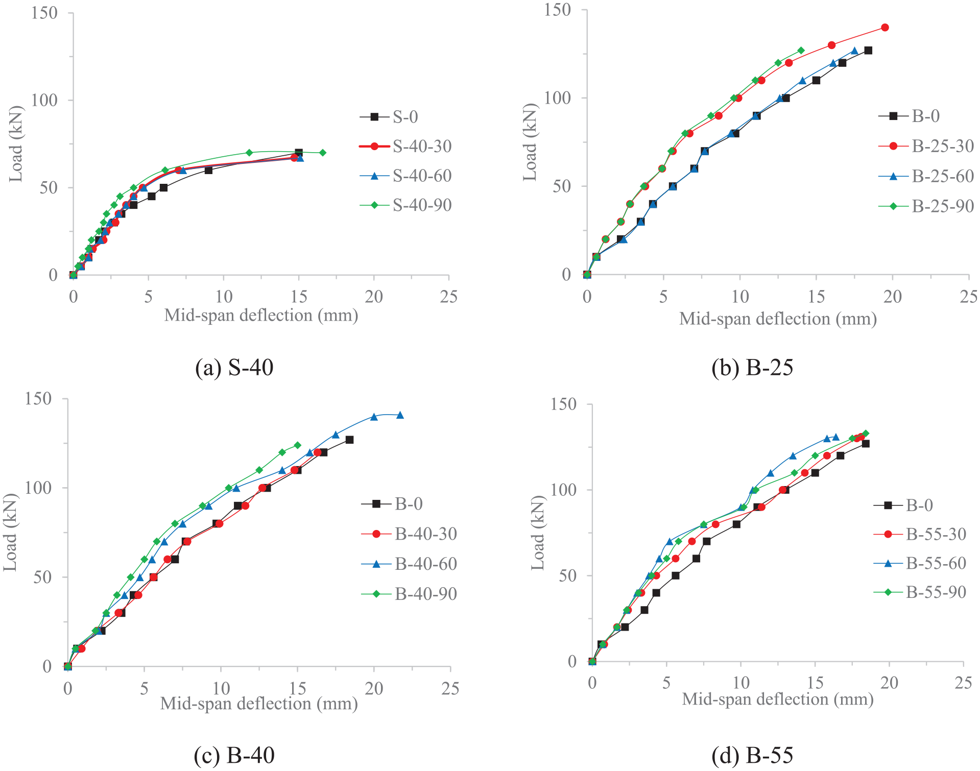
Load-deflection curves.
Cracking load and crack width
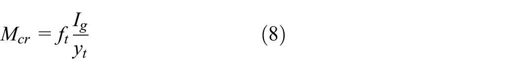
The values of the cracking load are shown in Table 4. A decrease in the cracking load may be attributed to the degradation in the tensile strength of the concrete or in the bond behaviour of the reinforcement of the concrete. The aging with an accelerated temperature in this study is insufficient to produce considerable corrosion of the steel bars embedded in concrete. As indicated by the data shown in Table 4, the CRS concrete beams have no degradation in their cracking load after aging. The increased value of S-40-90 may be caused by the prolonged maturation of the CRS concrete in the temperature-accelerated saline solution. The bond strength of the steel bar is also improved due to a low corrosion level. In contrast, the BFRP-CRS concrete beams exhibit a 25% decrease in their cracking load compared with that of the control beam (B-0). This decrease is caused by the slight degradation in the bond behaviour between the BFRP bar and CRS concrete, which has also been reported in other studies on the bond behaviour of the BFRP bars in ordinary concrete (Dong et al., 2016; El Refai et al., 2015). According to ACI 440, the cracking load is calculated by equation (8), with reference to ACI 440. The theoretical value of the cracking load of the CRS concrete beam is calculated to be 12.2 kN, which is consistent with the experimental results ranging from 10 to 15 kN in Table 4.
As demonstrated in Figure 10, the crack width of the aged beams with steel reinforcement increased substantially compared to the control beams, especially the crack width after the steel reinforcement yielded. In contrast, the BFRP-CRS concrete beams showed a considerable decrease in their crack width, which demonstrated the enhancement in the bond behaviour between the BFRP bar and CRS concrete. This phenomenon was consistent with the results obtained in a previous study (Jin, 2016), which showed a slight increase in the bond strength of 12-mm BFRP bars in CRS concrete after aging in a salt solution.
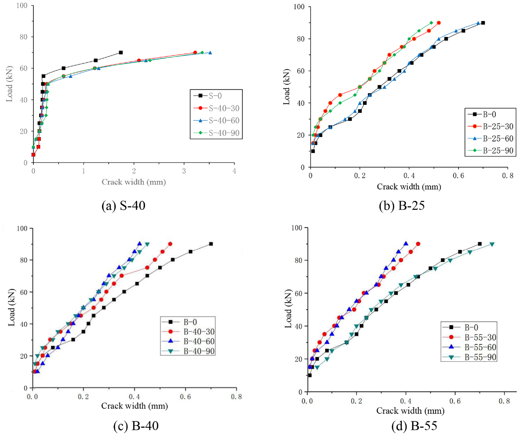
Load versus crack width curves.
Design method
Loading capacity
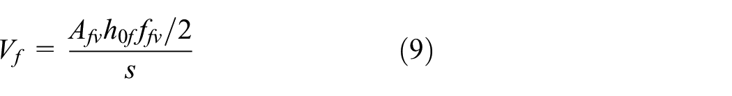
As discussed in Section 4.3, the failure mode of the CRS concrete beams transformed from flexural failure to shear failure after aging in a saline solution. Thus, it was recommended that the formula for calculating the flexural capacity of the beams remained unchanged, and the formula for calculating shear capacity should be modified to consider the degradation of the FRP stirrups in a marine environment. A partial factor equal to 2 was recommended for the tensile strength of the stirrups (ffv), and equation (6) was modified to produce equation (9). The formula for the shear resistance of the concrete remained unchanged. The theoretical value of the shear capacity (Vu) calculated by the modified formula was 58.6 kN, which did not exceed the minimum value of the shear capacity (59.9 kN on B-40-30) in this study. It is noteworthy that the retention of the tensile strength of the BFRP bar was 94.4% with exposure to a saline solution for 42 days (Wu et al., 2015), which was substantially higher than 50%. Thus, the FRP stirrups may experience a larger decrease in their strength when exposed to a harsh environment than that of the longitudinal FRP reinforcement.
Serviceability
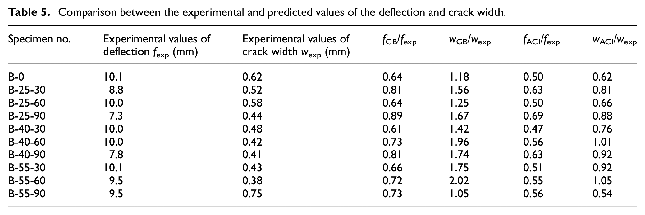
The serviceability of beams, for example, the deflection or crack width, largely depends on the bond behaviour of the longitudinal BFRP reinforcement with CRS concrete. The authors’ previous study showed no degradation of the bond behaviour of a 12-mm-diameter BFRP bar with CRS concrete after aging in a saline solution. Furthermore, a slight increase occurred in the bond strength due to the prolonged maturation of the concrete aged in a moist environment with an accelerated temperature. That increase was beneficial to the serviceability of the beam. The experimental values and the theoretical values of the deflection and crack width calculated by the formulae provided by Chinese and American standards are shown in Table 5. The values of the flexural stiffness and crack width at the moment of 0.67Mu were selected for the comparison because 0.67Mu was the average load level at which the crack patterns stabilised, and no additional cracks appeared. Considering the above factors, the formulae for the design of cross-sectional stiffness and crack width were modified as follows.
Comparison between the experimental and predicted values of the deflection and crack width.
Chinese standard GB 50608
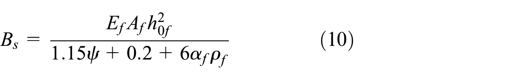
The flexural stiffness of a beam with a rectangular cross-section is calculated by
The crack width of a beam is calculated by
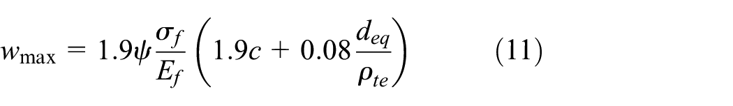
where ψ = the nonuniformity coefficient of the reinforcement strain, c = the thickness of the concrete cover measured from the extreme tension fibre to the outer edge of the FRP tensile reinforcement; and deq = the equivalent diameter of the FRP reinforcement.
American standard ACI 440.1R-2015
The formulae for the prediction of the effective moment of inertia (Ie) and crack width (w) recommended in ACI 440.1R-2015 are shown in equations (12) and (13).
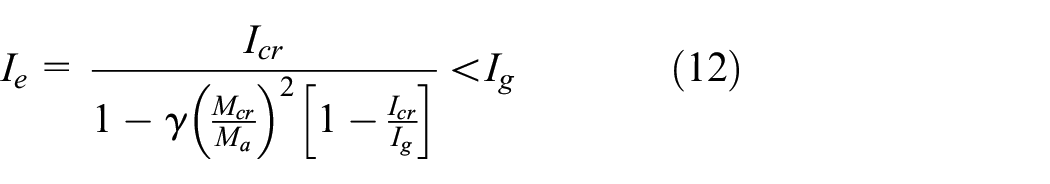
in which Icr = the moment of inertia of the transformed cracked section; Ig = the gross moment of inertia; Ma = the moment adopted as the service load (0.67Mu); and γ = 1.72–0.72 (Mcr/Ma).
where β = the ratio of the distance from the neutral axis to the extreme tension fibre to the distance from the neutral axis to the centre of the tensile reinforcement; kb equals 0.83 with reference to Elgabbas et al. (2016a); d c = the thickness of the concrete cover measured from the extreme tension fibre to the centre of the FRP tensile reinforcement.
As indicated by Table 5, the Chinese standard GB 50608 has a higher precision in the prediction of the deflection than that of the American standard ACI 440.1R, and both standards underestimate the deflection. ACI 440.1R is more accurate in the prediction of the crack width than that of GB 50608, which largely overestimates the crack width. The inaccuracy of the two standards in predicting serviceability might be caused by the scattered experimental data due to aging in a simulated seawater. Thus, a data base comprising the experimental results in existing literatures on the durability of concrete beams reinforced with FRP bars is necessary for the improvement of the prediction, which will be conducted in authors’ further study.
Conclusion
An experimental study on the durability of CRS concrete beams reinforced with BFRP bars or steel bars is presented in this paper. Flexural tests were conducted on two control beams and twelve beams aged in simulated sea water with accelerated temperatures. Based on the test results and discussion on the failure modes, capacities, deflections and crack development of the beams, the conclusions are summarised as follows.
(1) The BFRP-CRS concrete beams without aging exhibited a flexural failure mode, while a shear failure mode occurred for the beams after aging in a saline solution due to the substantial degradation in the strength of the BFRP stirrups. However, no degradation occurred in the loading capacity of the BFRP-CRS concrete beams. A partial factor equal to 2 was recommended for the strength of the BFRP stirrups in BFRP-CRS concrete beams exposed to marine environments.
(2) The aged steel and aged BFRP-CRS exhibited substantial increases in their stiffnesses compared with those of the control beams due to the prolonged maturation of the concrete. The crack width of the steel-CRS concrete beams exceeded that of the control concrete beams at the yielding stage of the steel reinforcement, while the BFRP-CRS concrete beams showed a considerable decrease in their crack width after aging.
(3) GB 50608 has higher precision in the prediction of the stress in the FRP tensile reinforcement at ultimate loads and the deflection than those of the American standard ACI 440.1R, while ACI 440.1R is more accurate in the prediction of the crack width in comparison with GB 50608.
Footnotes
Authors' Note
Shi Jianzhe is also affiliated with College of Civil and Transportation Engineering, Hohai University, Nanjing, China.
Declaration of conflicting interests
The author(s) declared no potential conflicts of interest with respect to the research, authorship, and/or publication of this article.
Funding
The author(s) disclosed receipt of the following financial support for the research, authorship, and/or publication of this article: The authors gratefully acknowledge the financial support provided by National Key Research and Development Programme of China (2017YFC0703000), and acknowledge Jiangsu GMV Co., Ltd. for providing BFRP bars.