
Abstract
This paper investigates the experimental and analytical behaviour of beam-column joints that are subjected to a combination of torque, flexural and direct shear forces, where different Carbon Fibre Polymer (CFRP) strengthening wraps have been applied only to the beam. These wrapping schemes have previously been determined by the research community as an effective method of enhancing the torsional capacities of simply supported reinforced concrete beams. In this investigation, four 3/4-scale exterior beam-column joints were subjected to combined monotonic loading; three different beam wrapping schemes were employed to strengthen the beam region of the joint. The paper suggests a series of rational formulae, based on the space truss mechanism, which can be used to evaluate the joint shear demand of the beams wrapped in these various ways. Further, an iterative model, based on the average stress-strain method, has been introduced to predict joint strength. The proposed analytical approaches show good agreement with the experimental results. The experimental outcomes along with the adopted analytical methods reflect the consistent influence of the wrapping ratio, the interaction between the combined forces, the concrete strut capacity and the fibre orientation on the joint forces, the failure mode and the distortion levels. A large rise in the strut force resulting from shear stresses generated from this combination of forces is demonstrated and leads to a sudden-brittle failure. Likewise, increases in the beams’ main steel rebar strains are identified at the column face, again influenced by the load interactions and the wrapping systems used.
Keywords
Introduction
The role of the beam-column joint is crucial in providing an efficient load path between the beam and column elements. Poorly detailed or inadequately designed reinforced concrete (RC) beam-column joints lead to excessive deformations and an increase in columns loads; ultimately, this may affect the stability of the structure. Thus, a large number of tests have been carried out to investigate the behaviour of RC beam-column joints under monotonic or cyclic loading; generally, these tests involved the concentric loading of the beams and columns (i.e. Davood and Alireza, 2017; Hamil, 2000; Mostofinejad and Hajrasouliha, 2019; Mostofinejad et al., 2018; Parker, 1997; Sarsam and Phipps, 1985; Sasmal, 2009; Triantafillou and Antonopoulos, 2003). However, in practice, structural members undergo a combination of both concentric and eccentric (torsion) loads during the construction stages and their working life. Torsional forces can result from alternating span loadings and direct eccentric loads, which can promote severe cracks in RC beams, especially in exterior frame joints. The presence of torsional forces reduces the shear and flexural capacity of RC members (Peng and Wong, 2011). Moreover, torsional forces increase the tensile stresses of the steel bars and effectively alter the plastic hinge locations (Ali and Forth, 2018). Since 2001, a number of torsional strengthening and upgrading schemes for RC beam members involving Fibre Reinforced Polymers (FRP) composites have been presented (Table 1). The use of FRP in this way is largely due to the simplicity of its installation and the superior physical characteristics of FRP over conventional retrofitting materials, such as steel and concrete.
Previous experimental research into the use of FRP as a torsional strengthening method for beams.
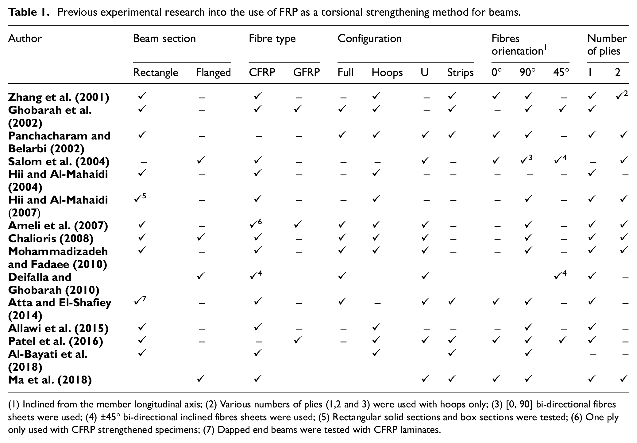
(1) Inclined from the member longitudinal axis; (2) Various numbers of plies (1,2 and 3) were used with hoops only; (3) [0, 90] bi-directional fibres sheets were used; (4) ±45° bi-directional inclined fibres sheets were used; (5) Rectangular solid sections and box sections were tested; (6) One ply only used with CFRP strengthened specimens; (7) Dapped end beams were tested with CFRP laminates.
In comparison to concentrically loaded joints, there has been much less research into the effect of beam torsion on joint behaviour. Research has concentrated on the influence of the eccentricity of the beam axis on the column axis (Kusuhara et al., 2004; Raffaelle et al., 1992; Shimizu et al., 2000), as well as the effect of transverse beams and slabs (Hassan, 2011). More recently, Elshafiey et al. (2016) did investigate the effect of beam torsional moments on beam-column joints. They found that the observed failures occurred in the joint regions due to a lack of joint stirrups and high beam stiffness.
Interestingly, the FIB Model Code (Fédération Internationale du Béton) (2010) and Eurocode 2 (2004) propose at the ultimate limit state that it is not necessary to consider torsion induced loading (by compatibility); to avoid excessive cracking, minimum reinforcement should be incorporated by way of stirrups and longitudinal bars (FIB Model Code, 2010). Similar guidance is also provided in the ACI Committee 318 (2014) for forces within the threshold limit (the threshold limit is defined as 25% of the torsional cracking moment). In summary, the general recommended design provisions for RC joints (ACI-ASCE 352R-02 Committee, 2002; BS8110, 1997; Eurocode 2, 2004; NZS 3101, 2006) do not provide guidelines to evaluate joint shear demand under combined actions, including torsion.
This paper investigates the influence of beam torque on equivalent exterior frame beam-column joints strengthened with various CFRP wrapping scheme. The paper proposes an analytical model that allows the prediction of joint forces and hence, capacities. In doing so, it presents the development of a number of formulae that can be used to evaluate the forces in the main tension ties and compression struts under the combined action of torsional, flexural and direct shear forces, depending on the different wrapping schemes.
Beam torsional strengthening schemes
A summary of the available research that has experimentally investigated externally bonded FRP systems for beams is presented in Table 1. It has been found that various improvements in beam torsional capacity could be achieved by using different wrapping systems. Based on the fibre orientation and the section wrapping system, the beam test configurations can be categorised into five main schemes – continuous vertically oriented wraps along the beam member; U-wrap; strip wrap (hoops); 45° oriented fibres; and horizontally oriented wraps. The vertically and 45° oriented carbon fibre arrangements attained the highest loading levels (Chalioris, 2008; Deifalla et al., 2013; Ghobarah et al., 2002; Panchacharam and Belarbi, 2002; Salom et al., 2004), whereas the partially wrapped arrangement (U-wrap) was less effective than the fully wrapping schemes and exhibited premature de-bonding. The influence of horizontally oriented fibres on beam torsional strength appeared to be insignificant (Patel et al., 2016; Zhang et al., 2001).
Although, several beam configurations using glass fibre reinforced polymers (GFRP) have been researched, typically they exhibited a drop-in enhancement level compared with the CFRP wraps (Ameli et al., 2007). As the effect of beam wrappings on joint integrity and stress variations have not been identified yet, this research investigates the influence of beam wrapping systems on stress levels in the tension chords and compression struts of beam-column joints, paying particular attention also to joint deformation and failure regions. Further, this study presents a rational approach to quantifying the increase in the stresses within the beam main rebars which transfer to the joint area as influenced by the proposed beam wrapping schemes. These wrapping schemes can potentially increase the beams’ capacities, stiffness and levels of plastic deformations to a sufficient level such that damage occurs in the column of the joint, negating the preferable strong column – weak beam behaviour. Hence, it is important to develop this rational approach such that the effects of the wrapping schemes (and any changes to the combined forces resulting from a change in building use or a structural change to the frame) can be accurately quantified; ultimately ensuring that the damage is kept away from the joint and is located in the beam itself.
Experimental programme
Specimen details
Four 3/4-scale exterior beam-column joints (SH-C-U, SH-S-C-A, SH-S-C-H and SH-S-C-I) were constructed using normal weight concrete and high strength steel bars. The specimens’ details are given in Table 2 and the member sections and dimensions are shown in Figure 1(a). The beam and column lengths of the exterior joint have been extended beyond the contra-flexure points (analytically determined as part of a hypothetical six-storey ordinary moment resisting frame). The members were designed according to the ACI Committee 318 (2014) recommendations, while the joint panel details satisfy the ACI-ASCE 352R-02 Committee (2002) recommendations – connection Type-1. Hooked end bars (90°) were used without any splice to provide a sufficient bonding length and to prevent anchorage failure in the joint’s horizontal bars. The joint’s aspect ratio is 1.05; it was noted that a number of previous studies have noted a decrease in joint shear capacity with an aspect ratio larger than 1.4 (Chun and Shin, 2014; Hamil, 2000). As part of the analysis of the hypothetical six-storey frame, a non-symmetrical distribution of live loads was considered between the floors and spans, such that the maximum induced beam torque did not exceed the threshold limit specified by ACI Committee 318 (2014). In the beam region, no additional torsional reinforcement was therefore provided.
Specimens details.
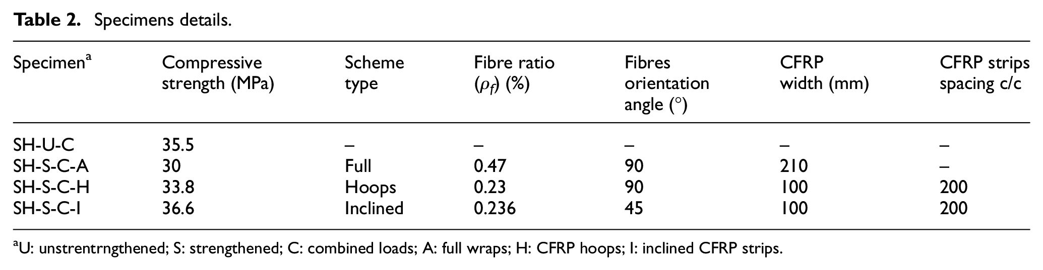
U: unstrentrngthened; S: strengthened; C: combined loads; A: full wraps; H: CFRP hoops; I: inclined CFRP strips.
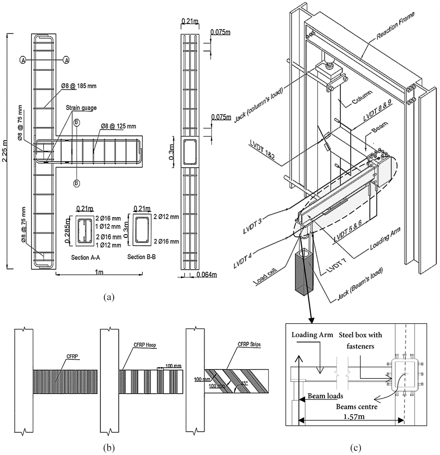
(a) Specimen details, (b) scheme details and (c) test set-up.
Material properties
The ultimate strengths of the steel bars are 560 MPa, 540 MPa and 570 MPa for the Φ16 mm, Φ12 mm and Φ8 mm, respectively. Three bars of each diameter were selected and uniaxial tensile tests were performed to determine the tensile strength. The average compressive results for concrete samples are given in Table 2, where the samples were tested at 28 days. Three effective CFRP wrapping schemes (full wrapping, hoops and 45° wraps) were employed to strengthen the SH-S-C-A, SH-S-C-H and SH-S-C-I specimens, as shown in Figure 1(b). Enhancements to the torsional strength of each joint specimen were evaluated in accordance with the FIB Bulletin 14 (2001) provisions. Surface preparation and corner rounding were performed before the sheets were applied to the concrete substrate. The coupon details of an un-impregnated unidirectional CFRP fabric are as follows: (1) tensile strength =2530 MPa, (2) tensile modulus=230 GPa, ultimate tensile strain = 1.5% and thickness = 0.22 mm. A medium viscosity resin (epoxy) was used to attach and impregnate the CFRP fabrics.
Test setup and instrumentations
All tests were conducted under monotonic loading. A rigid steel arm was attached to the end of the beam furthest from the column. The steel arm was orthogonal to the span of the beam (see Figure 1(c)) and allowed the monotonic point load to be applied via hydraulic jack at a distance of 1.57 m from the vertical centreline of the beam (the torque arm); this produced torque, in addition to bending and vertical shear. A constant compressive axial load of a pre-specified magnitude (
Several Linear Variable Differential Transducers (LVDT’s) were employed to measure the twist angle (LVDT 3 to 6) and joint deformations (LVDT 1 and 2), as illustrated in Figure 1(c). Also, a number of strain gauges were mounted on the steel bars of size 5 mm and size 2 mm on the CFRP sheets to capture the strain development through all loading stages.
Experimental results and discussion
The behaviour of the joint specimens is quantified in Figure 2. From Figure 2 it can be seen that the loading capacity increases proportionally with an increase in the wrapping ratio (
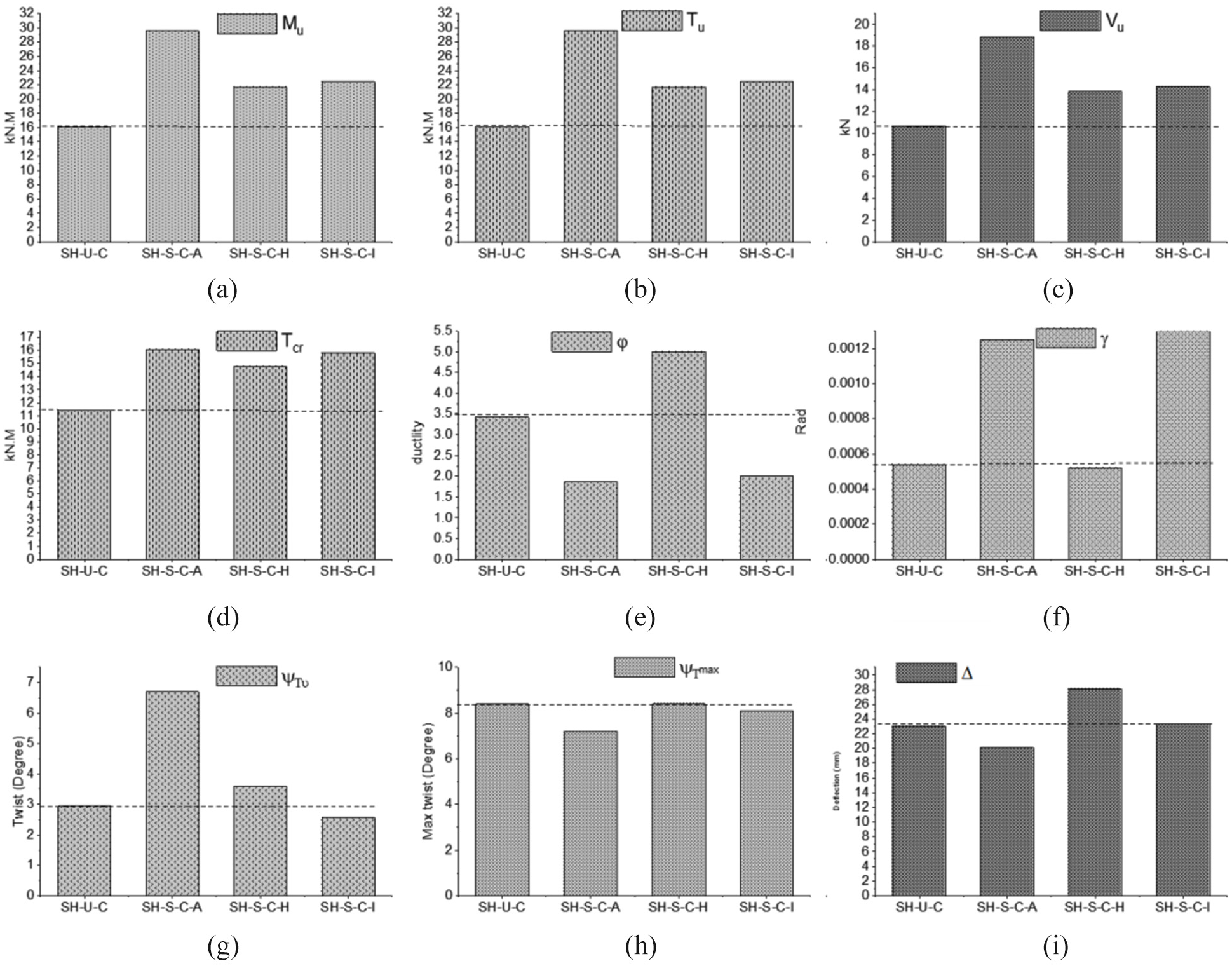
Tests results: (a) ultimate bending moment, (b) ultimate torque, (c) ultimate vertical shear, (d) cracking torque, (e) ductility index, (f) shear distortion angle, (g) twist angle at Tu, (h) max twist angle and (i) max. Beam deflection.
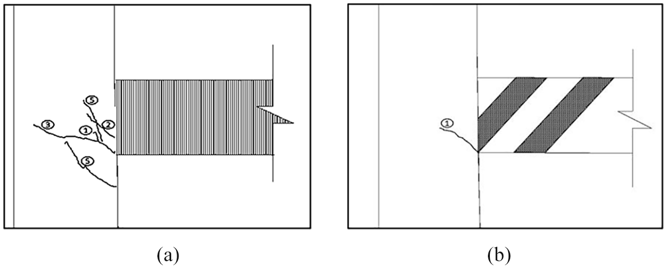
Joint cracks (a) fully wrapped specimen (SH-S-C-A) and (b) 45° degree wrapped specimen (SH-S-C-I).
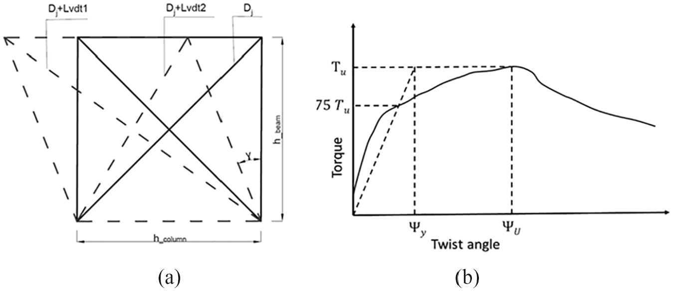
Schematic diagrams: (a) joint shear distortion angle, (b) ductility level, yield displacement of the reduced stiffness equivalent elasto-plastic system.
Failure of the specimens mainly occurred in the beam regions and was due to the crushing of the concrete struts. In comparison with the unstrengthened specimen (SH-U-C), the fully wrapped specimen (SH-S-C-A) exhibited beam damage which extended to the column face. The beam’s damage (SH-S-C-A) was concentrated in a region under relatively high bending moment near the column face, where the flexural compressive forces intensified the concrete strut forces that were induced by both the torsion and shear actions. Hence, when subject to torsion, it is crucial to improve the strength of the concrete strut in order to avoid catastrophic brittle failure. The compressive strength of the diagonal struts is greatly influenced by the softening of concrete (the cracking stage), which was enhanced due to the increase in orthogonal tensile stresses caused by shear stresses.
It was clear that by using CFRP hoops (SH-S-C-H) the cracking levels were reduced as compared with the control specimen (SH-U-C); see Figure 5(a) and (b). The CFRP hoops tend to reduce the cracking levels (e.g., during both the ascending and descending stages) and tend to improve the concrete response, that is, by (1) increasing the confinement of the concrete through the lateral pressure provided by the CFRP hoops, and (2) resisting the diagonal tensile stresses. Although the SH-S-C-I specimen experienced relatively lower concrete deformations and fewer cracks than the SH-S-C-H specimen after the cracking load was reached, sudden damage occurred in the concrete struts when the induced forces in the inclined compressive struts exceeded the softened concrete’s compressive strength, which impaired the member’s ductility.

Beam cracks: (a) SH-U-C specimen and (b) SH-S-C-H specimen.
Load-twist behaviour
During the first stages of loading, the behaviour of all tested specimens was very similar (Figure 6(a)) – this linear elastic behaviour continued with high torque-twist (Tcr–ψcr) rigidity up to the cracking load. As mentioned earlier, the strengthened specimens demonstrated different levels of enhancements to their cracking strength, although all exceeded the cracking strength of the unstrengthened specimen (SH-U-C).
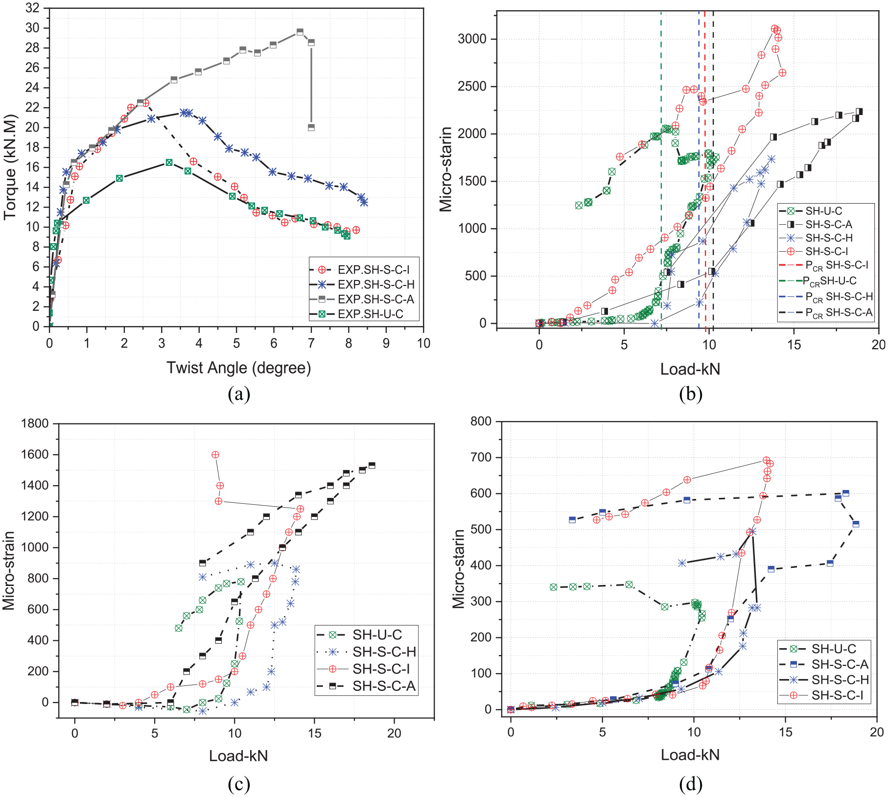
(a) Torque-twist angle diagram, (b) steel strain of the bottom main bars near the column face, (c) steel strain of the top beam main bars near the column face and (d) steel strain of the main bars in the middle of the joints.
These enhancements reflect the degree of confinement of the CFRP wraps and the fact that the CFRP wraps delay the cracks in the concrete by reducing the orthogonal tensile stresses. The strengthened specimens demonstrated a progressive increase in their load carrying capacities in the post cracking stage (ascending curves). Moreover, the strengthened specimens produced a larger torsional rigidity than the control specimen (SH-U-C), with both the SH-S-C-I and SH-S-C-A exhibiting a linear response up until the maximum load was reached. The SH-U-C-H specimen, on the other hand, exhibited a non-linear behaviour up to the maximum load this was as a result of the propagation of the beam’s concrete cracks starting immediately after the cracking load in the regions between the CFRP hoops. Further, there was yielding of the steel stirrups prior to the ultimate load.
The last stage (failure stage) for specimens SH-S-C-I and SH-S-C-H was identified following the loss of the member’s carrying capacity after the peak load was reached. At this stage, significant deterioration in the member’s torsional stiffness was observed due to severe concrete cracks, large plastic deformations in the steel stirrups and rupture of the CFRP strips. For the fully wrapped specimen SH-S-C-A, the declined failure stage did not develop due to brittle concrete failure, followed by the fracturing of the CFRP wraps shortly after the peak load.
Table 3 compares the strengthened specimens with the unstrengthened specimen in terms of cracking torque (ΔTcr), ultimate torque (ΔTu), torsional cracking rigidity (ΔKcr) and post-cracking rigidity (ΔKu), and illustrates the percentage increase in performance offered by the CFRP wrapping.
CFRP contribution for all specimens.
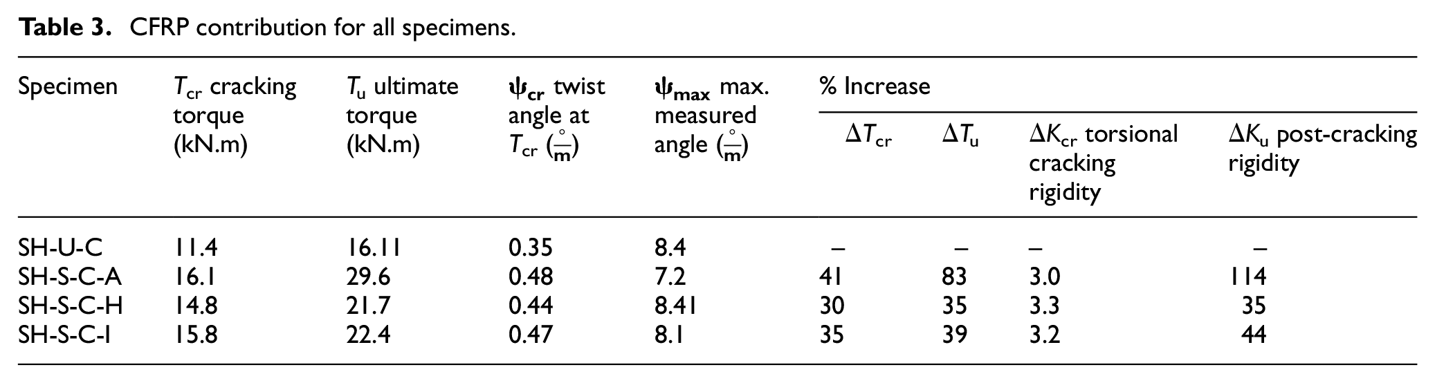
The specimens’ torsional rigidities (Kcr and Ku) were evaluated as the measured torque with respect to the unit angle of twist at the cracking and ultimate load, respectively. It can be concluded from Table 3 that the effectiveness of the CFRP wraps in increasing the member’s torsional rigidities is significantly pronounced during the post-cracking stage. These increases in post-cracking rigidities (ΔKu) ranged from between 35% for the CFRP strip schemes and 114% for full continuous wraps. In contrast, the influence of these external wrapping schemes before cracking (ΔKcr) was not very significant.
Ductility levels
The ductility index has been evaluated as the ratio of rotation (ψu) at the peak load and the yielding point, as schematically illustrated in Figure 4(b). An equivalent elastic-plastic system was employed to identify the equivalent yielding point for the specimens, as they exhibited different levels of cracking and yielding through the loading stages, along with the yield displacement of the reduced stiffness, an equivalent elastic-plastic system was employed. This system was suggested by Park (1988).
Figure 2(e) shows the ductility index for all beam-column joints; it can be noticed that the member’s ductility in terms of torque-twist (T-ψ) has reduced in accordance with the level of torsional forces attained. As a result of incorporating beam torsion, the failure of the specimens mainly occurred in the beam regions and was attributed to progressive degradation in the concrete’s strength (as observed for SH-U-C and SH-S-C-H), or sudden crushing of the concrete struts with the complete rupture of the CFRP sheet (as observed in the failure of SH-S-C-A), both significantly reduced the ductility level. The T-ψ ductility indices demonstrate that the specimens were considerably affected by the degree of wrapping, with the highest level of ductility being achieved when CFRP hoops were used. However, the brittle failure of the fully wrapped specimen illustrates the need for a balance between the enhancement level due to the wrapping schemes and the concrete strut’s capacity. Further, the ductility levels for all specimens can be adversely affected if the specimens exhibit joint shear failures, anchorage failure, or slippage of the beam tension rebars within the joint region. Therefore, the increase in the joint’s demands due to both combined forces and wrapping schemes should be quantified, with a view to avoid brittle shear failures in the joint zones.
Strain developments
A decrease in the member loads occurred once the steel rebars yielded. There was also a severe deterioration in the stiffness of the beam after the rupture of the CFRP wraps and when yielding of the steel stirrups had occurred. Figure 6(b) and (c) show that a higher tensile strain developed in the bottom steel (flexural tension zone) of the beam (yielded) than in the top steel, due to the fact that the torsional and bending forces were additive. Based on the truss mechanism, the increase in strain in the transverse reinforcement increased the angle of the inclined struts such that they became steeper and reduced the amount of stress in the longitudinal main rebars. This is reflected in the behaviour of the SH-S-C-H and SH-C-S-A specimens, where under the same load levels they produced lower strain values than the unstrengthened control specimen (SH-C-U). For the SH-S-C-I, the inclined wraps tended to reduce the concrete strut angle and produce larger longitudinal strains (plastic deformations). In the middle of the column zone, the levels of developed strains in the beam’s bottom rebars had decreased due to the forces in the steel being transmitted by bond into the concrete within the joint zones (Figure 6(d)). However, the joint steel ties of all the specimens exhibited insignificant strain rates (less than 130 micro-strain), as a tie strain emerges under high joint shear forces near the failure load (Hamil, 2000).
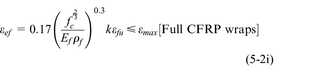
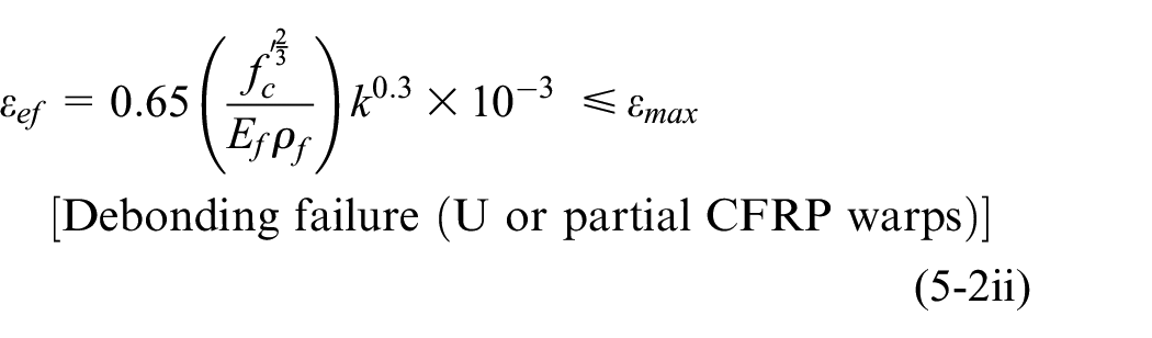
Figure 7(a) and (b) show the strain development in the CFRP sheet and steel stirrups at a distance of 250 mm away from the joint zone. These figures reveal that significant strains occurred in the CFRP sheets and beam steel stirrups due to the shear stresses. The CFRP wraps were highly strained in the regions close to the failure zones (see SH-S-C-I and SH-S-C-A specimens). The inclined CFRP configuration (SH-S-C-I) exhibited early strain development, which was consistent with the main rebar’s deformations, as mentioned earlier. A good agreement can be observed between the maximum observed strain levels and the evaluated effective strain (
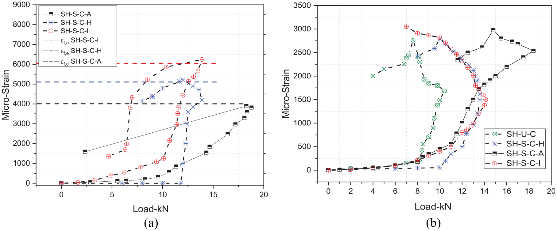
(a) CFRP strain at 250 mm from column face and (b) beam stirrup strain.
Concrete strut capacity and shear demand
The occurrence of torsion with other forces, such as flexure and vertical shear, is quite common. This combination of forces produces a variation of strain around the perimeter of the cross-section and over the member’s length. The test results of this investigation conform with the space truss analogy, as the combination of flexural and shear stresses magnified the tension forces in the beam’s main rebars, along with the compression forces in the concrete struts. In this context, during the post-cracking stage, the space truss model is formed from the longitudinal and transverse ties and the concrete struts. Thus, to diminish the crushing of concrete resulting from the interaction between the direct shear and torque, this study attempts to limit the torsional enhancement levels (via the CFRP) to the concrete strut capacity (
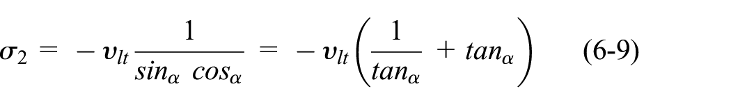
The reduction in concrete strut capacity-vertical component (
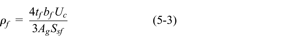
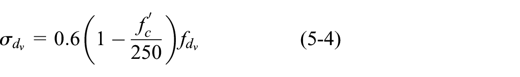
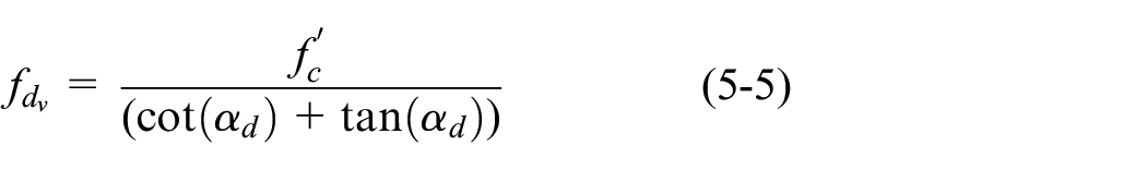
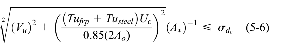
Where
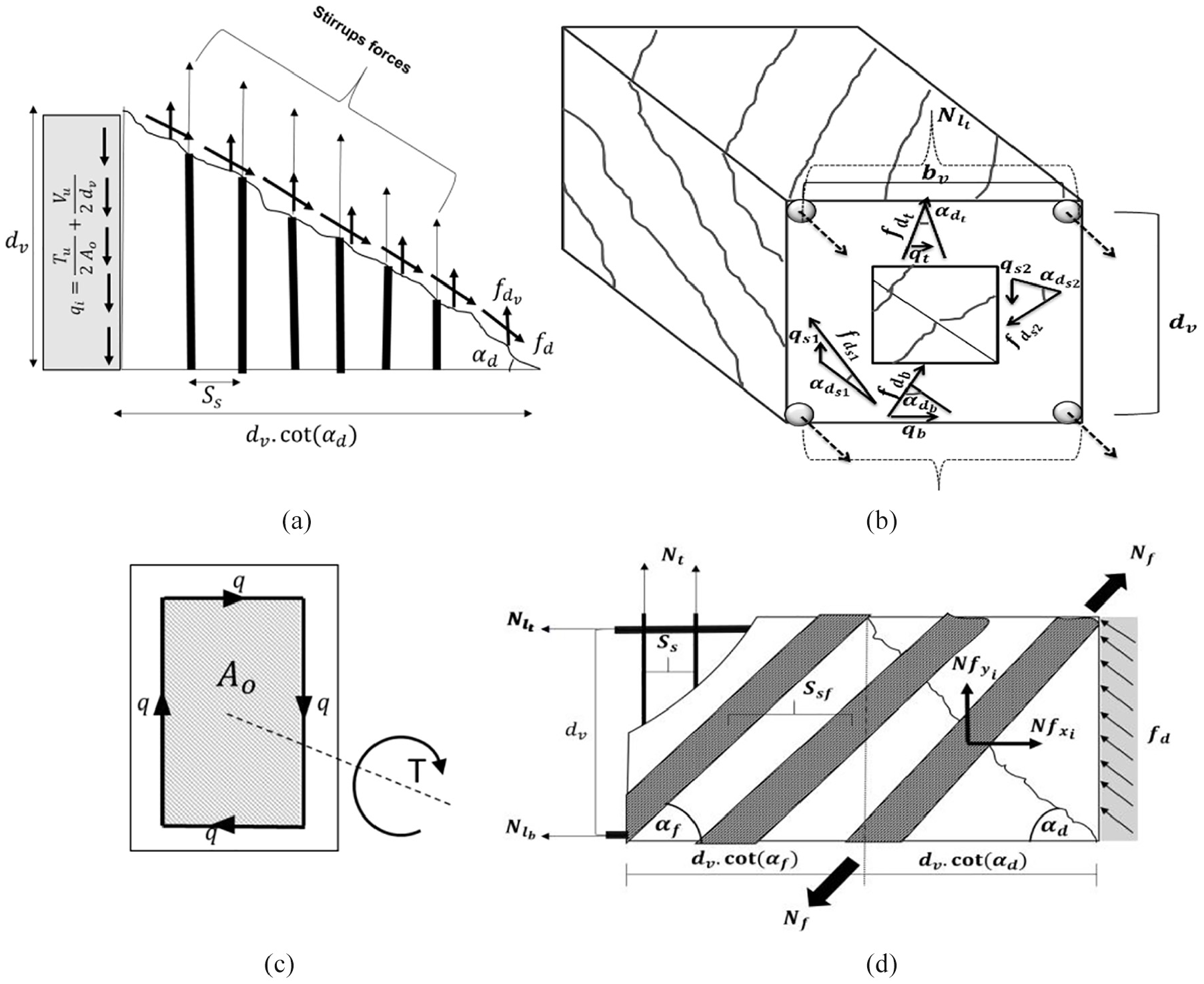
(a) Truss mechanism at the side wall, (b) space truss mechanism, (c) shear flow and the section’s effective area and (d) truss mechanism for inclined fibres.
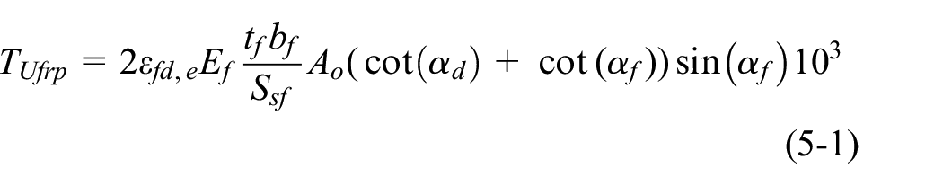
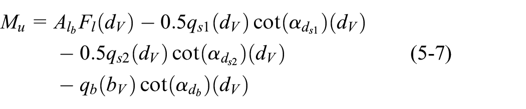
The joint shear demand (joint forces) resulting from the combination of the beam forces can be quantified according to the truss mechanism. The interaction between torsion, bending and direct shear according to the space truss analogy was reported by Elfgren (1972) and later by Rabbat and Collins (1978), and Hsu (1996). This present study has extended this method to evaluate the tensile forces in the main rebars in the flexural tension zone of the beam, by considering the effect of the various CFRP wrapping schemes and subsequently establishing the relevant formulae that conform to the truss method. Equation (5-7) satisfies the equilibrium of forces by taking a moment about the top chords (Figure 8(b)) – the bottom beam’s side being exposed to tensile stresses induced by the flexural and torsional forces.
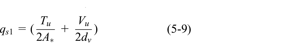
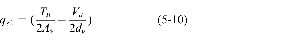
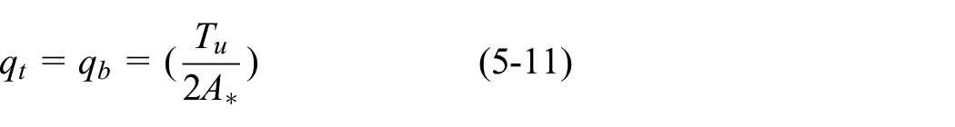
The amount of shear flow (
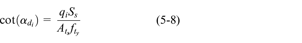
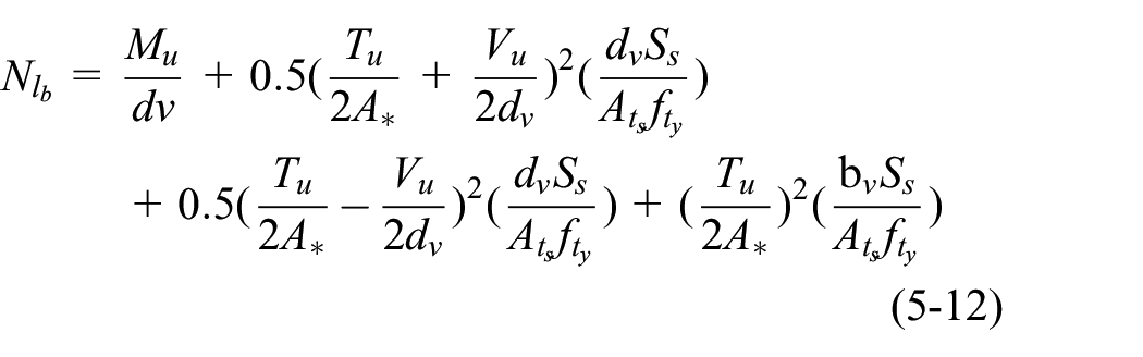
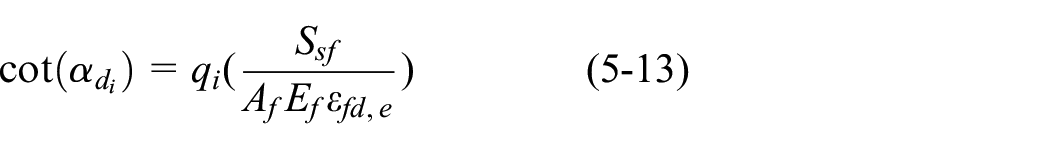
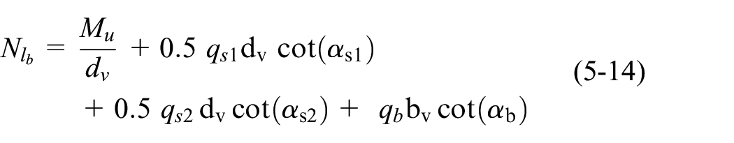
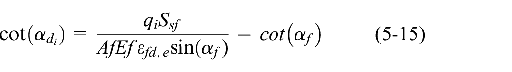
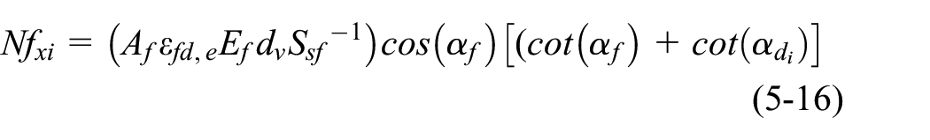
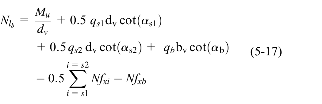
The evaluation of tensile forces in the main rebars for the strengthened members with vertically oriented wraps needs to consider the influence of the fibre wraps on the inclination angles of the concrete struts of the beam’s four sides (left, top, right and bottom). This can be achieved by accounting for the contribution of the CFRP layer in the vertical direction, as given in equation (5-13); where the evaluated angles of inclinations based on equation (5-13) should not be more than that obtained from equation (5-8). Otherwise, the inclination angle is controlled by the yielding of the steel reinforcement before the rupture of CFRP. Following the same steps that were used to develop equations (5-12) and (5-14) is introduced to compute the peak tensile forces in the main steel rebars under the combined actions. Similarly, the CFRP contribution can be adopted for the inclined configuration. However, the relationship between the angle fibre strips and concrete struts (which is illustrated in Figure 8(d)) has to be determined by establishing force equilibrium in the vertical direction for all sides, as given in equation (5-15). Equation (5-16) is then derived to compute the tensile forces in the inclined CFRP strips along the horizontal direction, where the resultants of these forces are considered at the middle of each wall of the section. Again, rearranging and substituting equations (5-15) and (5-16) in (5-7) produces equation (5-17), which allows the computation of the tensile force in the main rebars, with different orientations of fibres.
The proposed formulas can be modified to account for the different directions of flexural forces (e.g., negative bending moment), which would induce the yielding of the upper chords. This can be simply performed by equating the applied bending moment to the internal resisting moment at the bottom side and by following the same procedure to compute the angles of inclinations, shear flow and rebar forces.
Where Tu is the total torque in N.mm;
Analytical models of beam-column joints
It is essential to recognise both the shear transfer mechanism of the forces that develop at the joint boundaries and which failures of the RC beam-column connections resulted from inadequate shear strength. Considering the complications involved in the shear mechanism and the influencing parameters that affect the joint’s behaviour, a number of empirical and semi-empirical models have been developed to estimate the strength of the joint. Also, several theoretical models have been developed that are derived from the strut-tie theory. These include the fixed angle softened strut-and-tie model (Hwang and Lee, 1999), the modified rotated angle strut-and-tie model (Wong, 2005), the general multi-strut-and-tie model (Pantelides et al., 2002), and the generalized monotonic strut-and-tie model (Parker, 1997). In general, these models mainly require the node dimensions of the struts to be defined; these correspond to the compression zone depths for the beams and columns at the joint boundaries. These models are intended to be applicable to beam-column joints under flexural and axial loads. Alternatively, the panel truss mechanism (compression strut fields-tension ties) for the joint load transfer has been identified by Paulay et al. (1978) and adopted by NZS 3101 (2006). Based on the panel truss mechanism, the Panel Zone Principal Stress-Strain Model was introduced by Pantazopoulou and Bonacci (1992). This model satisfies the equilibrium of forces, compatibly of strain, and the materials’ constitutive law. Further, Paulay et al. (1978), Tsonos (1996), and Tsonos (2008) developed joint models by considering the panel mechanism and direct strut action. These theoretical models have been verified against concentrically loaded members.
In contrast, this study aims to utilise the concepts of the average stress-strain distributions according to the panel zone principal stress-strain method that was developed by Pantazopoulou and Bonacci (1992), to predict the joint strength and distortion level when subjected to the set of combined forces. This study re-derives and modifies the panel zone principal stress-strain formulas (Pantazopoulou and Bonacci, 1992) using an iterative approach to satisfy (1) the equilibrium conditions which correspond to the panel truss and the diagonal strut mechanisms proposed by Paulay et al. (1978); Tsonos (1996); Tsonos (2008), (2) the rotating angle theory and (3) the compatibility conditions according to Mohr’s circle. Also, this proposed iterative model accounts for the softening of concrete according to an established constitutive model (Belarbi and Hsu, 1995). This approach will also allow the joint distortion to be determined in combination with the joint shear demands; it has been adopted as a more traditional direct strut method, which is based mainly on the equilibrium conditions of the stresses. This means that the strain compatibility, material constitutive conditions, node forces, along with their dimensions, are generally extremely complicated to define under the intricate loading conditions based on the direct strut method found in this investigation.
Based on the concept of average stresses proposed by Pantazopoulou and Bonacci (1992), the distribution of normal stress and shear stress are considered uniform across the joint. The stresses along the main bars of the beam and top face of the joint are illustrated Figure 9(a), where a significant proportion of the beam stresses were introduced into the joint by bond stresses (equal and opposite to the rebar forces
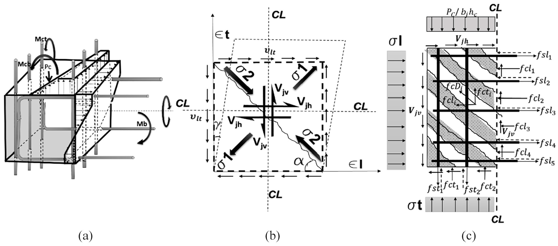
(a) Stress variation along steel bars, (b) kinematics of the joints and (c) forces and average stresses in the joint’s section.
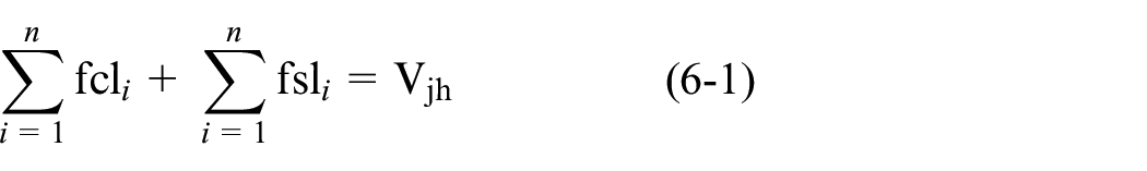
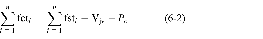
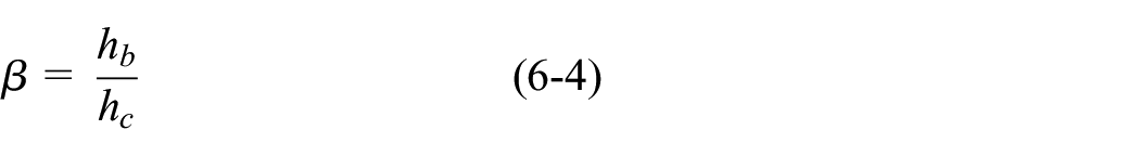
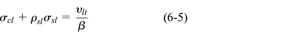
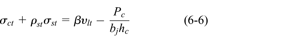
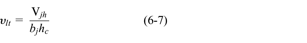
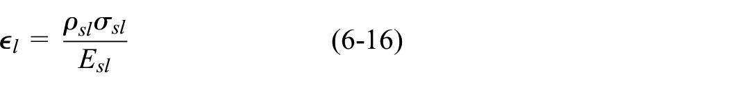
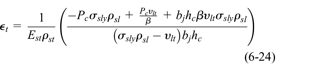
Referring to Figure 9(c), the equilibrium of forces in the horizontal (l) and transverse (t) directions are given in equations (6-1) and (6-2), respectively. The total forces acting in the joint core correspond to the panel truss; the diagonal strut mechanisms are equated to the joint shear forces (Vjh and Vjv) (Paulay et al., 1978; Tsonos, 1996; Tsonos, 2008), where the force components (fcli and fcti) of the concrete strut (fcDi) are added to the truss model forces (e.g., fsli and fsti ) in the horizontal and vertical direction; these forces equate to the shear demands (Vjh and Vjv) in the same direction; further, the column axial force is incorporated in equation (6-2) in satisfying the equilibrium of the joint. The vertical shear forces can be evaluated according to equations (6-3) and (6-4) (Paulay et al., 1978). Equations (6-5) and (6-6) restate the equilibrium of forces to comply with the average stresses of the two orthogonal directions (

Where, fsli and fsti are the forces in the longitudinal and transverse reinforcements, respectively in N; fcli and fcti are the forces in the concrete strut in the longitudinal and transverse directions, respectively in N;
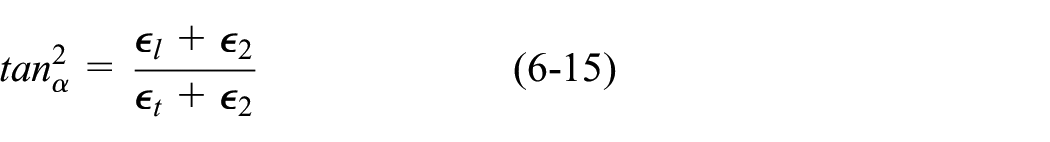
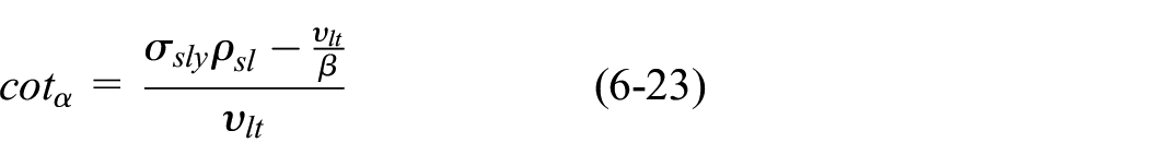
To evaluate the angle of inclination (
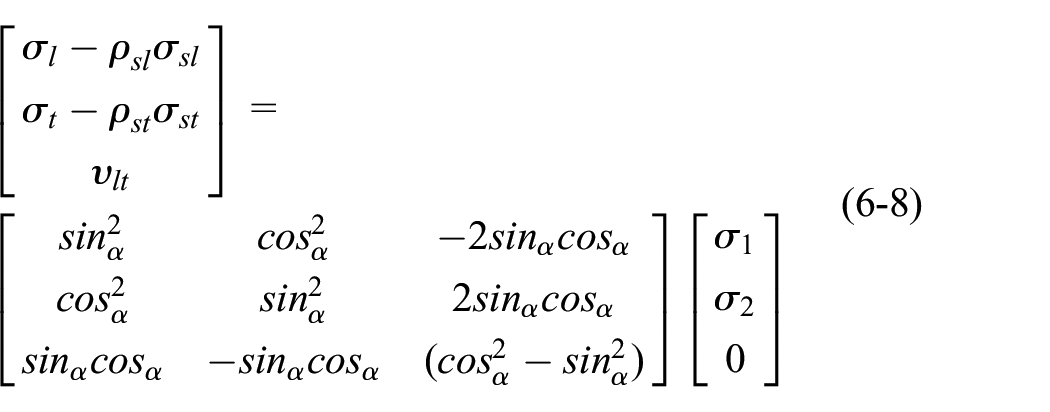


Three compatibility equations based on Mohr’s circle of strain that were reported by Vecchio and Collins (1986) have been used. The relationship between the strain components (

Where
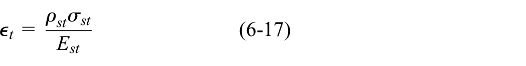
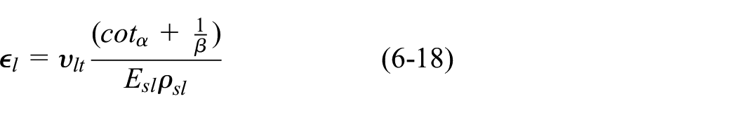
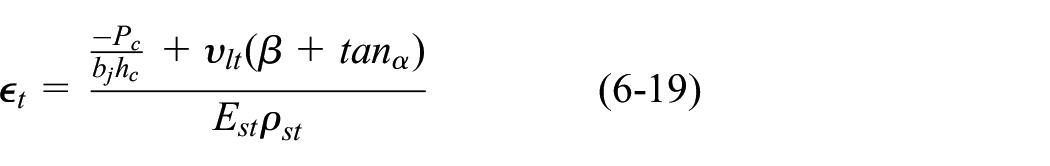
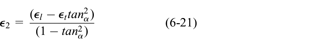
Referring to the previous equations and relationships between the stresses and strains in the concrete and the reinforcement, the sum of equations (6-5), (6-6), (6-10) and (6-11) produce equations (6-18) and (6-19) which allow the evaluation of (

A rapid decrease in the joint’s strength after the yielding of the shear joint’s ties occurred was reported by Bonacci and Pantazoupoulou (1993). Thus, when
The capacity of the compression inclined cracked concrete strut is reduced in accordance with the increase in the tensile strain (
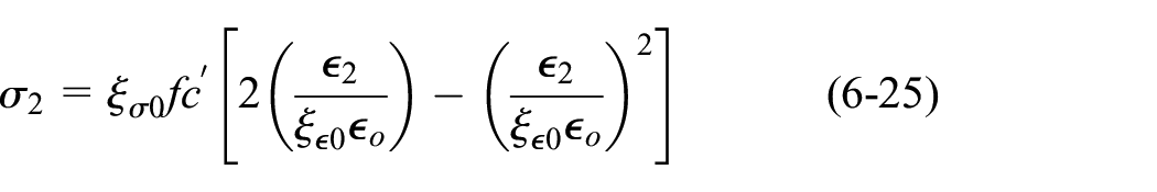

Where
To solve the set of equations presented in this Section, a flow coded program was developed using MATLAB programme. The solution flow chart is illustrated in Supplemental Appendix I; an iterative method was used to check the concrete strut capacity and the yielding of the bars by incrementing the joint shear (
Model validation and discussion
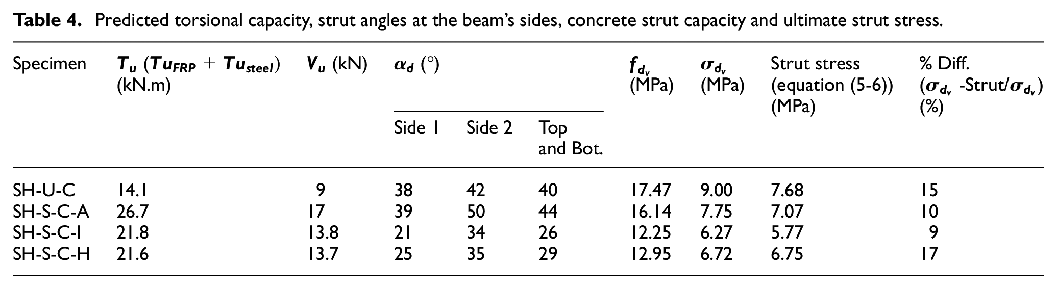
The peak tensile stresses in the beam’s bottom steel for all specimens (SH-U-C, SH-S-C-A, SH-S-C-I and SH-S-C-H) were calculated according to the equations presented in the previous Section (concrete strut capacity and shear demand) and then compared to the tests results (see Figure 10). Figure 10(a) shows good agreement between the predicted and experimentally obtained results, with a mean value of 0.98 for the ratio of the test to the model results and a corresponding coefficient of variation (COV) of 2%. Table 4 illustrates the predicted ultimate torsional capacity for the tested specimens, along with the computed concrete inclination angle (
Predicted torsional capacity, strut angles at the beam’s sides, concrete strut capacity and ultimate strut stress.
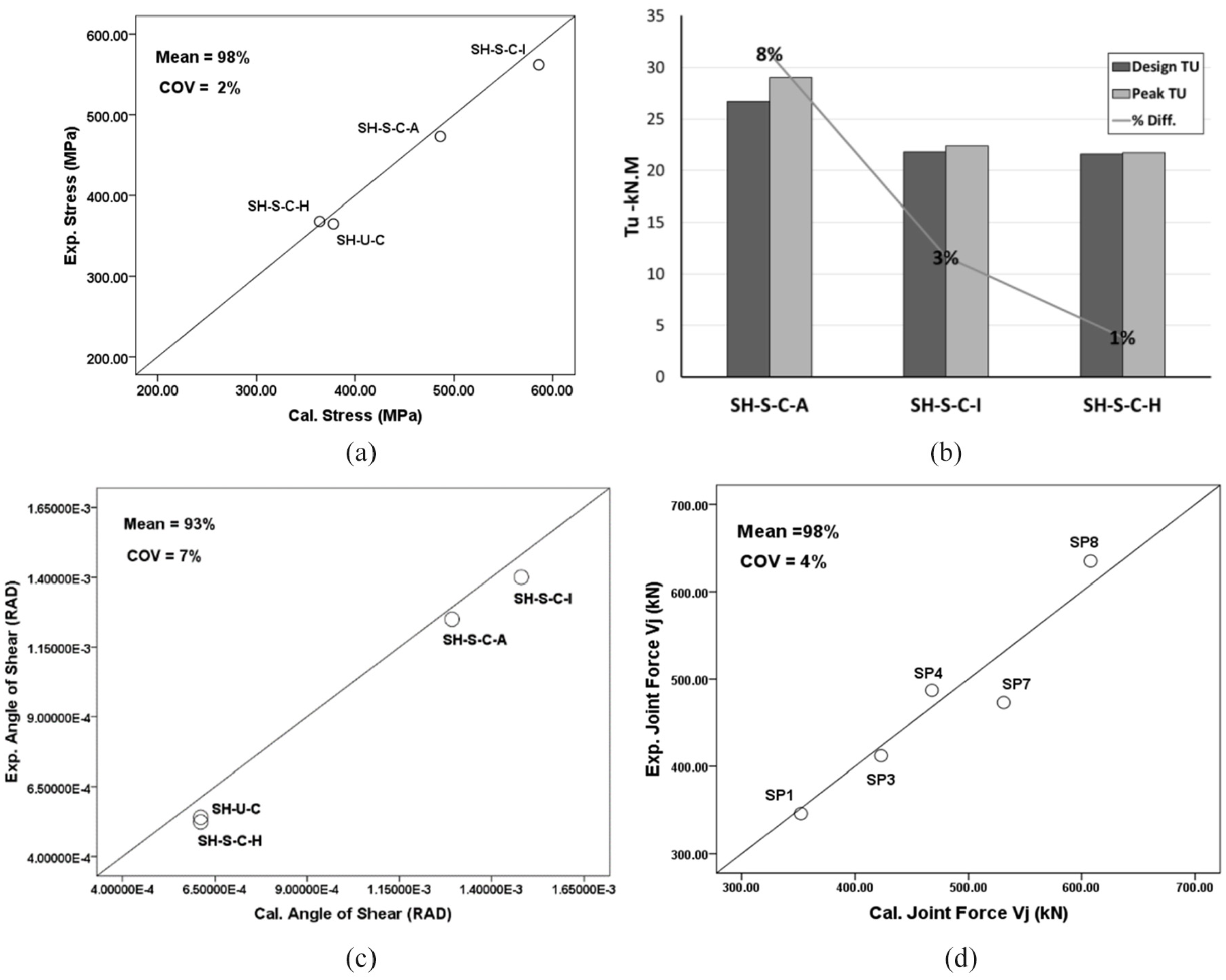
Experimental versus predicted results: (a) bottom stinger forces, (b) design and peak Tu, (c) max. joint distortion angles and (d) max. joint forces (Vj).
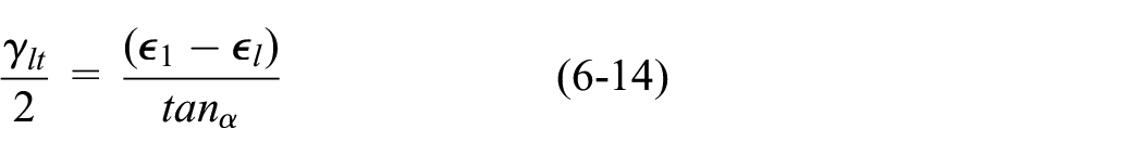
The shear distortion angle of the joint zone for each specimen was evaluated according to equation (6-14). The comparison between the model and the tests in terms of angle of distortion is shown in Figure 10(c). In this figure, it can be seen that the model can successfully predict joint deformation when it is subjected to different beam forces (shear demands). However, to verify the adequacy of the model and to predict the ultimate joint capacity (failure loads), the tests results of five unstrengthened RC beam-column joints (SP1, SP3, SP4, SP7 and SP8), as reported by Elshafiey et al. (2016) were considered. These five specimens failed in the joint zones under combined loading. A comparison between the predicted results using the model developed in this investigation and the tests results from Elshafiey et al. (2016) in terms of maximum joint force (Vj) are shown in Figure 10(d). Again, a good correlation is seen, with a mean value of 98% for the ratio of the experimental to the predicted Vj; the COV is equivalent to 4%.
The model developed in this investigation has been formulated to evaluate the influence of an increase in beam load on the joint’s integrity, which is mainly caused by additional torsional forces that are proportional with the beams’ strengthening schemes. It considers that the beam’s forces are essentially transferred into the joint zone by the main steel, while the beam’s flexural compressive forces at the joint’s boundaries (the beam’s compressive stress block) will be less effective in accordance with the ratio of torque to bending. The magnitude of the main rebar forces corresponds to the level of bending, torsional and shear forces (equations (5-12), (5-14) and (5-17)) that can be carried by the beam. However, the beam carrying capacity is limited by the concrete strut strength (equation (5-6)), while the effect of the transverse reinforcement (stirrups and CFRP) are represented in the strut’s inclination angle (equations (5-8), (5-13) and (5-15)), in which both components have an effect on the strut and the steel forces (equations (5-5), (5-12), (5-14) and (5-17)).
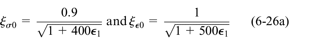
Similarly, the shear resistance capacity of the joint zone through all the solution stages is limited by the peak strength of the softened concrete (equations (6-25) and (6-26)). The derived expressions in Section 6 account for the effect of the reinforcement ratios (
Conclusions
The behaviour of the four reinforced concrete exterior beam-column joints have been discussed and analysed. In general, the test outcomes demonstrated the influence of beam wrapping (with full and partial CFRP wrapping configurations) on both failure modes and the joint demands. The viability of using CFRP wrapping systems to enhance member carrying capacities under torsional actions was confirmed. The enhancement levels were affected by the fibre ratio, the degree of confinement and the fibre’s orientation. Ductility of the members was reduced owing to the degree of concrete strut degradation, which was related to the magnitude of shear stresses produced by the addition of torsion and shear forces and due to the degree of wrapping. To avoid the concrete crushing, this study recommends limiting the reinforcement forces that resulted from the superposition of the CFRP and rebars, such that the capacity of the concrete struts is not exceeded. The strain readings confirmed the influence of the torsional forces; these forces increased the tensile stresses in the beam steel, which affected the shear demand and distortion levels of the joints. It was clear that the joint’s shear forces that were transferred into the joint from the beam’s reinforcement would be underestimated if they were based only on the bending stresses without any consideration for the torque and shear forces. Apart from beams loaded in flexure, no code provisions for RC joints exist to quantify the joint shear demands arising from combined beam loading (flexure, torsion, shear).
This study proposes a number of formulas based on the truss mechanism which are intended to be used to quantify the joint forces and which consider the effects of combined loads and different wrapping schemes. It also introduces a design approach which accounts for the level of developed compression forces due to shear-flow levels in order to prevent a concrete failure. Finally, it develops an iterative model, according to the average stress concept, that can be used to predict the joint capacity. This model addresses the softening of the concrete and the truss and inclined stress field mechanisms and has been verified against independent experimental data.
Supplemental Material
sj-pdf-1-ase-10.1177_13694332211007371 – Supplemental material for An experimental and analytical investigation of reinforced concrete beam-column joints strengthened with a range of CFRP schemes applied only to the beam
Supplemental material, sj-pdf-1-ase-10.1177_13694332211007371 for An experimental and analytical investigation of reinforced concrete beam-column joints strengthened with a range of CFRP schemes applied only to the beam by Sarmad Abdulsahab Ali and John P. Forth in Advances in Structural Engineering
Supplemental Material
sj-pdf-2-ase-10.1177_13694332211007371 – Supplemental material for An experimental and analytical investigation of reinforced concrete beam-column joints strengthened with a range of CFRP schemes applied only to the beam
Supplemental material, sj-pdf-2-ase-10.1177_13694332211007371 for An experimental and analytical investigation of reinforced concrete beam-column joints strengthened with a range of CFRP schemes applied only to the beam by Sarmad Abdulsahab Ali and John P. Forth in Advances in Structural Engineering
Supplemental Material
sj-pdf-3-ase-10.1177_13694332211007371 – Supplemental material for An experimental and analytical investigation of reinforced concrete beam-column joints strengthened with a range of CFRP schemes applied only to the beam
Supplemental material, sj-pdf-3-ase-10.1177_13694332211007371 for An experimental and analytical investigation of reinforced concrete beam-column joints strengthened with a range of CFRP schemes applied only to the beam by Sarmad Abdulsahab Ali and John P. Forth in Advances in Structural Engineering
Footnotes
Acknowledgements
The authors wish to acknowledge the contribution of the Ministry of Higher Education and Scientific Research of the Republic of Iraq for funding this research project.
Declaration of conflicting interests
The author(s) declared no potential conflicts of interest with respect to the research, authorship, and/or publication of this article.
Funding
The author(s) received no financial support for the research, authorship, and/or publication of this article.
Supplemental material
Supplemental material for this article is available online.
References
Supplementary Material
Please find the following supplemental material available below.
For Open Access articles published under a Creative Commons License, all supplemental material carries the same license as the article it is associated with.
For non-Open Access articles published, all supplemental material carries a non-exclusive license, and permission requests for re-use of supplemental material or any part of supplemental material shall be sent directly to the copyright owner as specified in the copyright notice associated with the article.