
Abstract
In this study, cyclic loading tests were conducted on reinforced concrete (RC) portal frames with brace-type friction dampers. The boundary conditions that could reproduce the axial forces exerted on the beams were adopted. To resist the axial force acting on the RC member, a damper connection method was employed by using steel inserted through the center of the RC member. The purpose of this study was to a) understand the behavior of the damper connection and the RC frame with brace-type friction dampers based on experimental tests and b) to confirm the effectiveness of the new connection method. According to the test results, the proposed connection method achieved effective damper connections in the RC frames. For the RC frame specimens with dampers, it was confirmed that the damper reached its sliding force and started to dissipate energy at an early stage with story drift ratios smaller than those at RC beam yielding. The welded part of the gusset plate and the steel inserted through the center of the RC beam were broken. When the welded part inside the beam broke and the axial deformation of the beam increased, the sliding displacement of the damper decreased. Therefore, a reliable jointing method of this part needs to be established.
Keywords
Introduction
Dampers have stable hysteretic characteristics and are effective in ensuring the earthquake resistance of reinforced concrete (RC) frames. Dampers have been used as energy-dissipating devices to retrofit RC frames in Japan. Damper applications in newly built RC moment-resisting frames have also been explored, wherein efficient and reliable connections between dampers and concrete components are critical. In addition, in the case of installing a brace-type damper, it is necessary to consider that the horizontal component of the damper force acts on the beam as an axial force. However, at present, the axial force of the beam has been neglected. The number of studies on this type of damper is still limited.
Dolce et al. (2005) conducted the shaking table test on the RC frame with brace-type dampers made of special alloys. Benavent-Climent et al. (2014) conducted the shaking table test on the RC frame with a brace-type web-plastification damper. Mahrenholtz et al. (2015) conducted experiments on the seismic retrofitted RC frame using buckling restrained braces. Several studies have been performed on the RC frame protected with brace-type steel dampers (e.g.,: Bai et al., 2021a, 2021b; Maida et al., 2012; Mazzolani et al., 2009; Qu et al., 2013; Sarno and Manfredi, 2010). These studies showed that the installation of the dampers in the RC frames was effective for seismic response control and for improvement of the energy dissipation performance as well. However, the axial forces generated in the column and the beam members based on the attachment of the damper were not considered.
In this study, a friction damper with high-stiffness hysteretic characteristics was used. The friction damper was developed in the 1980s. Since then, various types of friction damper devices have been developed, and various studies have been conducted on structures with the use of friction dampers.
Pall and Marsh (1982) proposed a new seismic design concept for steel-framed buildings by incorporating sliding friction devices in the bracing system of these buildings. The dynamic analysis results of the inelastic and temporal history yielded a superior performance for the friction-damped braced steel frames compared with computed responses obtained from other structural framing systems. Filiatrault and Cherry (1987) proposed a new friction damping system for steel-moment-resisting and braced-moment-resisting frames. The proposed system was based on brake lining pads placed at the intersections of cross-brace frames. Earthquake simulator table tests were conducted on a three-story friction-damped braced frame (FDBF) to demonstrate the superior performance of the FDBF. Fitzgerald et al. (1989) proposed an energy dissipation device that used friction resistance in slotted bolted connections in braced steel frames. Experiments showed that the device was effective in improving the seismic resistances of structures. Bhaskararao and Jangid (2006) conducted a numerical study on the structural responses of two adjacent buildings connected with friction dampers. The optimum slip force and optimum placement of the dampers were studied. López-Almansa et al. (2012) conducted shaking table tests on two reduced-scale steel models of a building frame that incorporated friction dissipators. The seismic efficiency of the friction dissipator was evaluated with numerical and experimental approaches. Iskhakov and Ribakov (2012) proposed the application of friction dampers for RC frame buildings and showed that they were effective in improving the seismic resistance. Qu et al. (2020) proposed a friction damper installation in a steel-coupling beam at the mid-span between coupled walls. The friction damper exhibited stable hysteretic responses and full-energy dissipation in coupling beam subassemblage tests. Several other studies have been conducted on the newly developed friction dampers (e.g.,: Eldin et al., 2020; Javidan and Kim, 2019; Veismoradi et al., 2021; Wang et al., 2020). All these studies demonstrated the effectiveness of installing friction dampers in buildings in seismic response control and improvement in the energy dissipation performance.
In context of the above-mentioned summary, in this study, cyclic loading tests were conducted on RC frames with brace-type friction dampers based on the new connecting method. The steel members were passed through the RC frame to resist the axial force generated by the damper. The purpose of this study was to understand the behavior of the damper connection and the RC frame with brace-type friction dampers and to confirm the effectiveness of the new connecting method. Effectiveness of brace-type damper can open channels for many valuable applications in RC buildings.
Test program
Test specimens
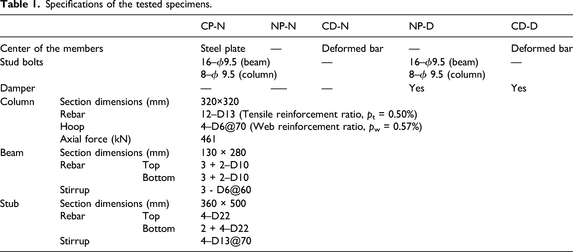
Specifications of the tested specimens.
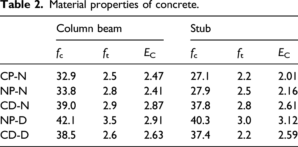
Material properties of concrete.
Material properties of rebar.
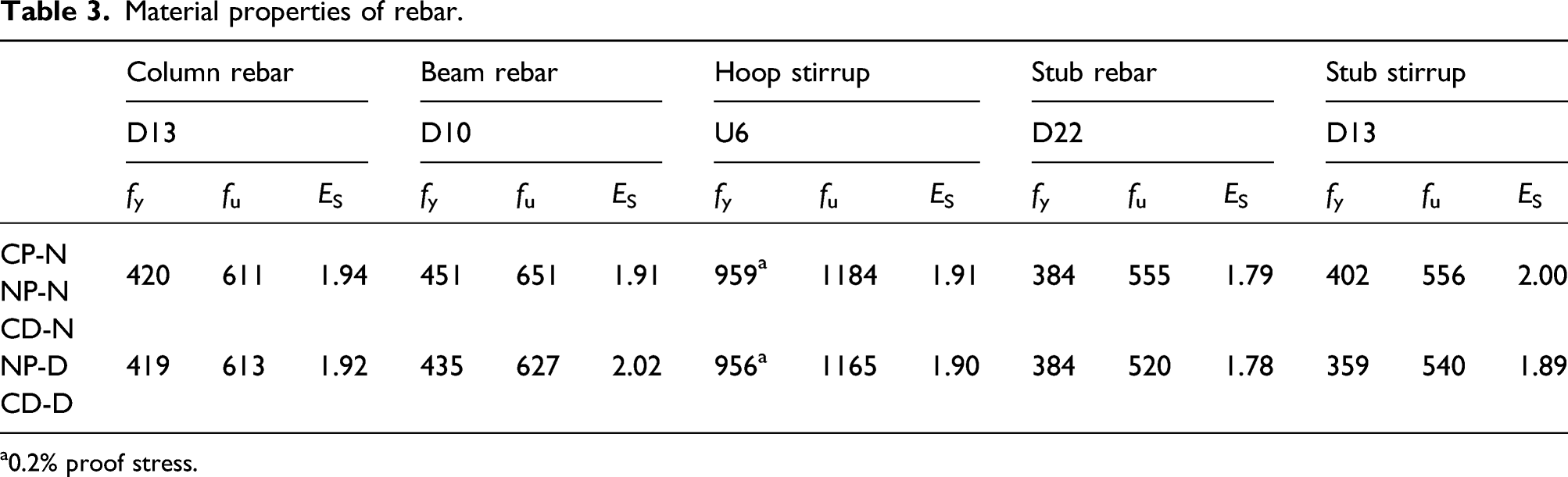
a0.2% proof stress.
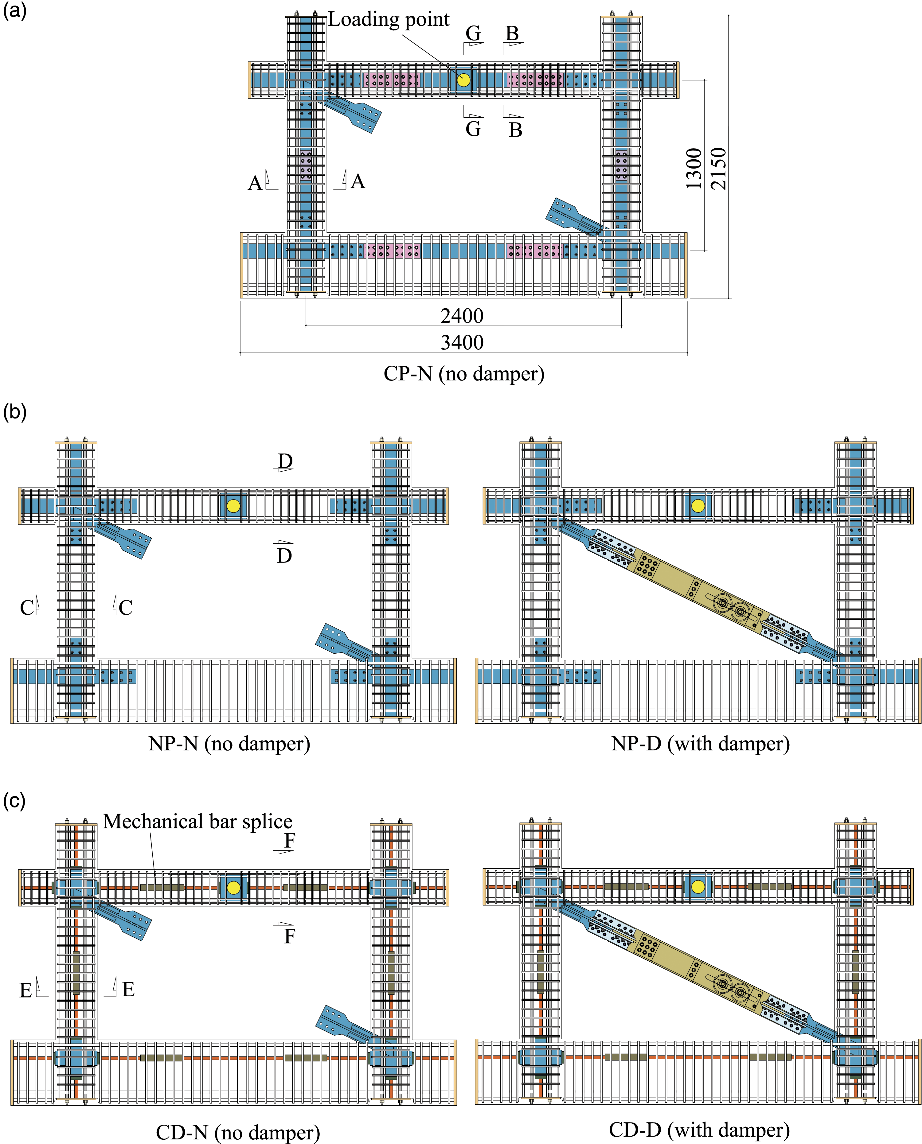
Outlines of the specimens: (a) CP (center plate) series, (b) NP (no plate) series, and (c) CD (center deformed bar) series (unit: mm).
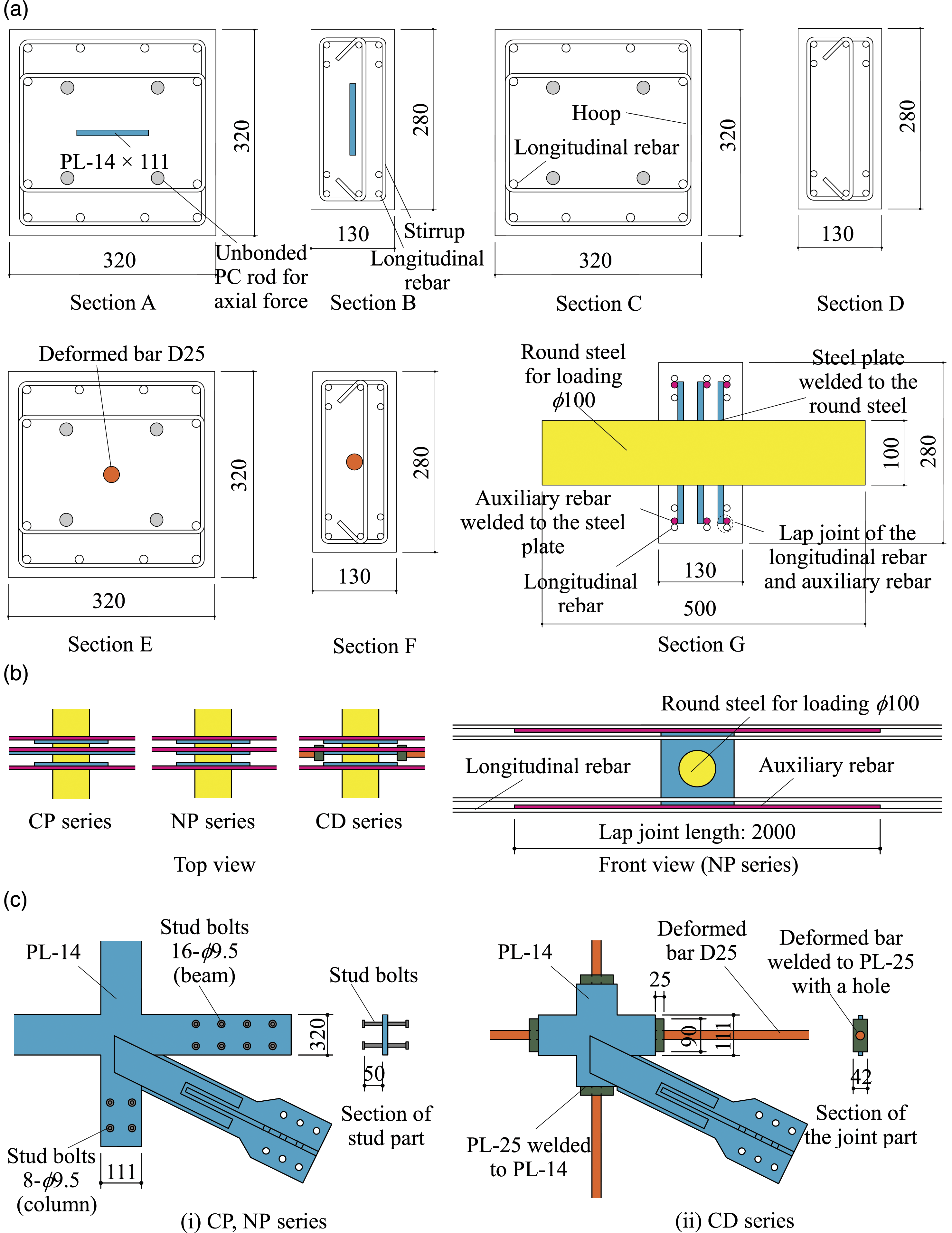
Details of the specimens: (a) cross-section, (b) loading point, and (c) gusset plate (unit: mm).
The specimen comprised single-story, single-span RC frames having approximately 1/3 scale columns and beams in the lowest story of a seven-story RC building designed for trials based on the Architectural Institute of Japan (AIJ) Standard for Structural Calculation of Reinforced Concrete Structures (Architectural Institute of Japan, 2010a). High-strength hoop and stirrup were used to improve the shear strength of columns and beams. The axial force ratio of the column was set to 0.15, and the axial force was applied through an unbonded prestressing rod. A steel plate with a gusset plate (G.PL) was embedded in the beam-column joint to connect the damper. In the finite element analysis performed before the test (Maida and Sakata, 2020), the calculated value of story shear force at the beam flexural yield of the RC frame was approximately 400 kN.
Figure 3 shows the components of the friction damper (Takahashi and Suzui, 2000; Takeda, 2012) used in this study (referred to as the “disc springs bolt unit”). The friction pad fastened to the outer steel plates, and the stainless-steel plates fastened to the inner steel plate slided over each other, frictional heat was generated, and vibration energy was converted into heat energy. The normal force on the friction surfaces was generated by fastening the high-tension bolt and was stabilized by the disc spring washer. The advantage of using disc spring washers is that they do not significantly relax under load over time. The inner steel plate and the stainless-steel plates fixed to it were provided with slotted holes to avoid immobilization of the high-strength bolts. The friction pad used phenolic resin. The friction coefficient of this friction surface was approximately equal to 0.3. Components of the friction damper.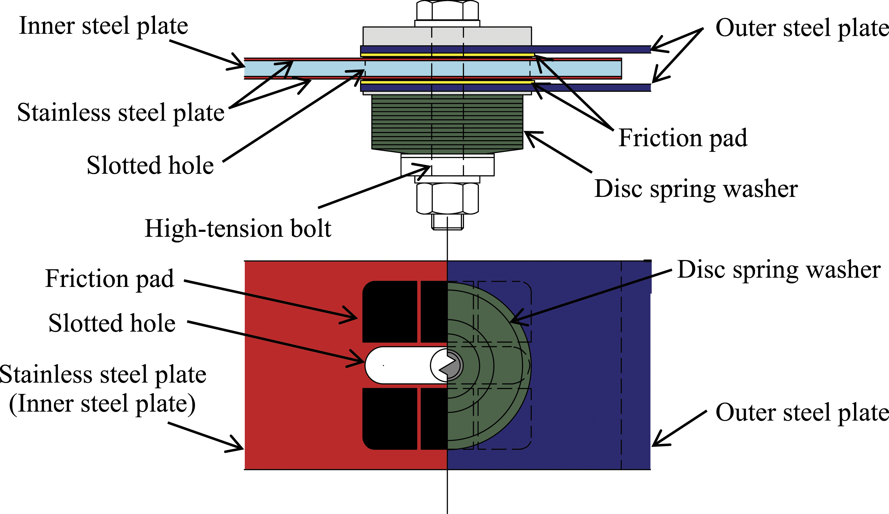
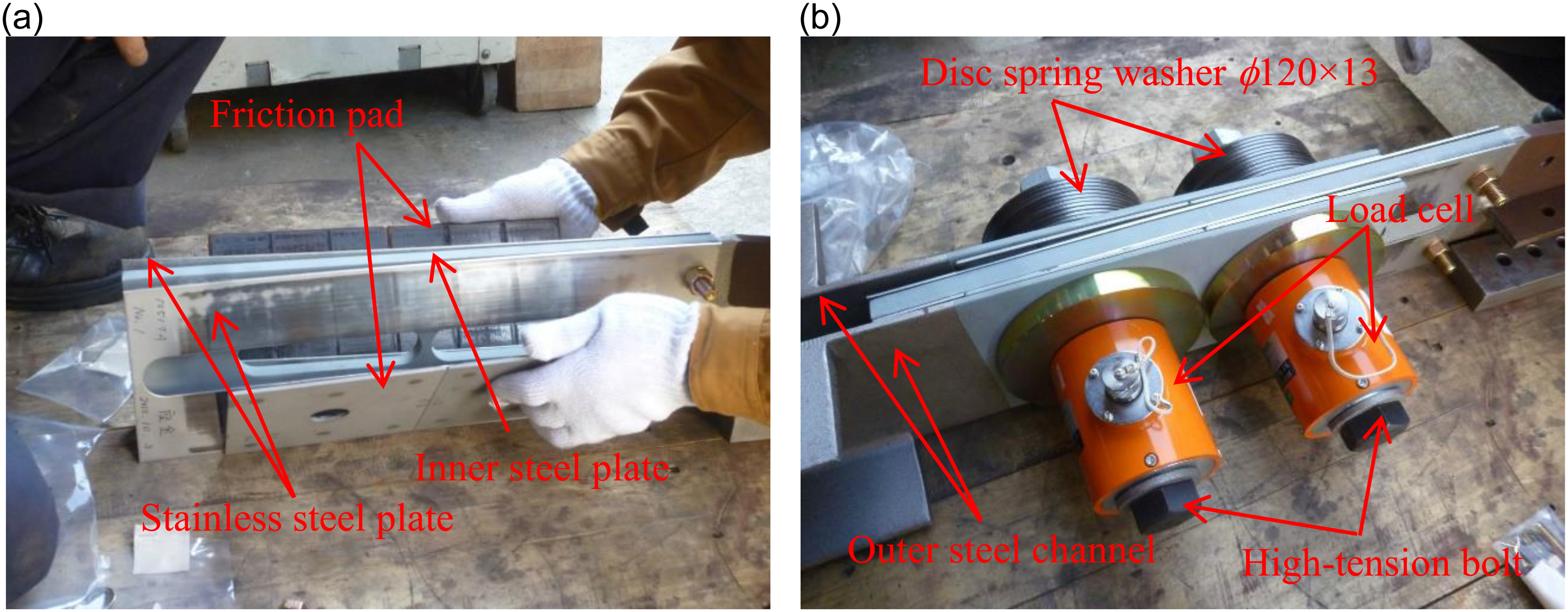
Figure 4 shows the details of the brace-type friction damper used in this study, and Figure 5 shows its configuration. Hereinafter, the “brace-type damper” is simply referred to as the “damper.” There were two disc-spring bolt units and two friction surfaces per bolt units. The high-strength bolt fastening force was 197 kN per bolt. Therefore, the sliding (yield) force in the damper NDs was calculated to be equal to 236 kN, estimated as the product of the friction factor (0.3), the bolt fastening force, the number of disc springs bolt units, and the number of friction surfaces. The damper mounting angle to the RC frame α was set to 26.1°, and the sliding force in the damper NDs was set to 236 kN so that the ratio of the horizontal component in the damper to the calculated story shear force at the beam flexural yield of the RC frame was approximately 1:2. The maximum sliding displacement of the damper was designed to be ±50 mm. Details of the brace-type friction damper (unit: mm). Configuration of the brace-type friction damper: (a) friction surfaces and (b) disc spring bolt unit.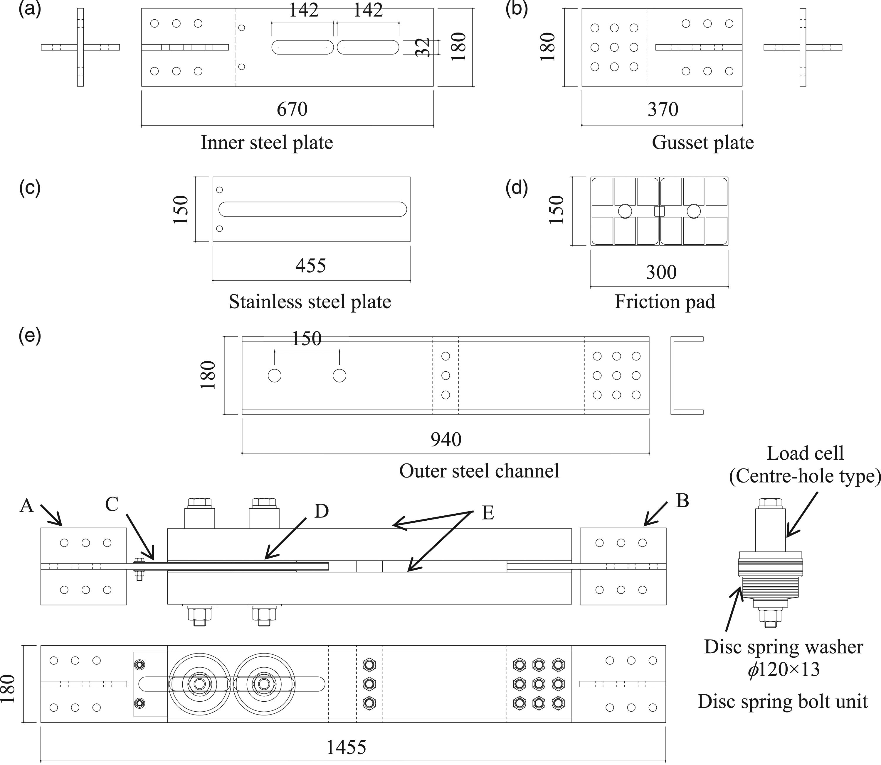
Connection details
A total of three series of five specimens were tested. These were the center plate (CP) series of the specimen in which steel plates passed through the RC frame and the no plate (NP) series of the specimen in which steel plates did not pass through the RC frame. The G.PL for the damper connection in the NP series was only embedded in the RC column and beam ends. In the CP and NP series specimens, the stud bolts were welded to the G.PL at the RC column and beam ends to resist the force in the damper (Figure 2(c, i)). The center deformed (CD) bar series was the third specimen in which the deformed bar passed through the RC frame to resist the force in the damper. The deformed bars passed through the columns, and the beams were welded to G.PL to connect the dampers (Figure 2(c, ii)). The deformed bar passing through the RC frame and concrete were bonded.
Only specimens without dampers (CP-N) were used in the CP series (Figure 1(a)). In the NP series (Figure 1(b)) and CD series (Figure 1(c)), the presence or absence of a damper was used as a parameter. NP-N was without a damper in the NP series. NP-D was with a damper in the NP series. CD-N was without a damper in the CD series. CD-D was a specimen with a damper in the CD series.
The steel plates and deformed bars inside the beams of the CP and CD series were designed to remain within the elastic range subject to the horizontal component of the force in the damper. It is expected that the concrete cracks will close after unloading if the steel inside the RC member was in the elastic range. Both the inner parts of the column and the beam were set to PL-14 × 111 mm (SN400) in the case of the CP series specimen, and to D25 (25 mm diameter deformed bar) (SD490) in the case of the CD series specimen. The steel dimensions and steel type were designed so that the yield strength Fy calculated as the product of the specified yield strength fy (fy = 235 N/mm2 for SN400 and fy = 490 N/mm2 for SD490) and the cross-sectional area of steel A (A = 1554 mm2 for PL-14 × 111 and A = 506.7 mm2 for D25) exceeded the horizontal component of the force in the damper (NDscos = NDs × cos α = 236 × cos 26.1° = 212 kN).
This force was determined by the following
The deformed rebar that passed through the center of the cross-section of the column was the same as that in the beam.
The stud bolts that were intended to be welded to the steel plates in the CP and NP series were designed based on the Design Recommendations for Composite Constructions (Architectural Institute of Japan, 2010b) regarding the force in the damper. The stud bolts used on the beam and column had 16–ϕ9.5 and 8–ϕ9.5 characteristics. The embedded lengths of the stud bolts were 50 mm (Figure 2(c, i)).
Test setup
Figure 6 shows the details of the loading and pin jigs, and Figure 7 shows the test setup. Upon loading, the stub of the specimen was first fixed to the reaction frames. To reproduce the axial force that acted on the beam, a jack was connected at the center of the beam as a pin support. The pin jig hole (ϕ100.1) passed through the round steel for loading (ϕ100) installed at the center of the RC beam to form a pin joint. The pin jig and the loading jig were joined by bolts. Additionally, the loading jig and 1000 kN jack were connected. Regarding the loading on the beam, three steel plates were welded to the center of the round steel beam (ϕ100), and an auxiliary rebar was welded to the steel plate at positions along the longitudinal rebar of the upper and lower beams. The auxiliary rebar and the longitudinal rebar were lap joints (Figure 2). Details of the loading and pin jigs. Test setup and measurement.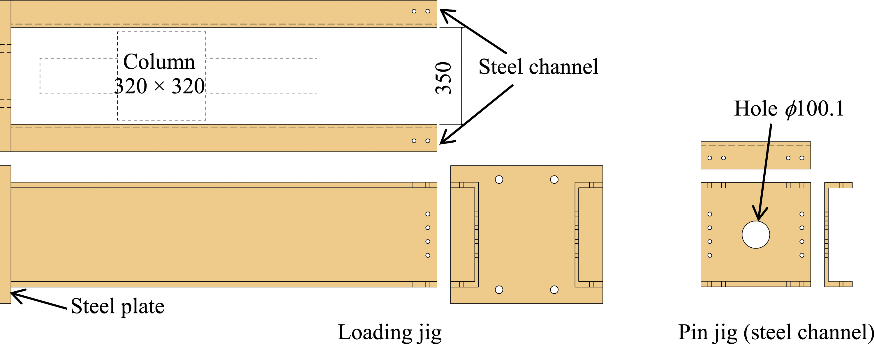
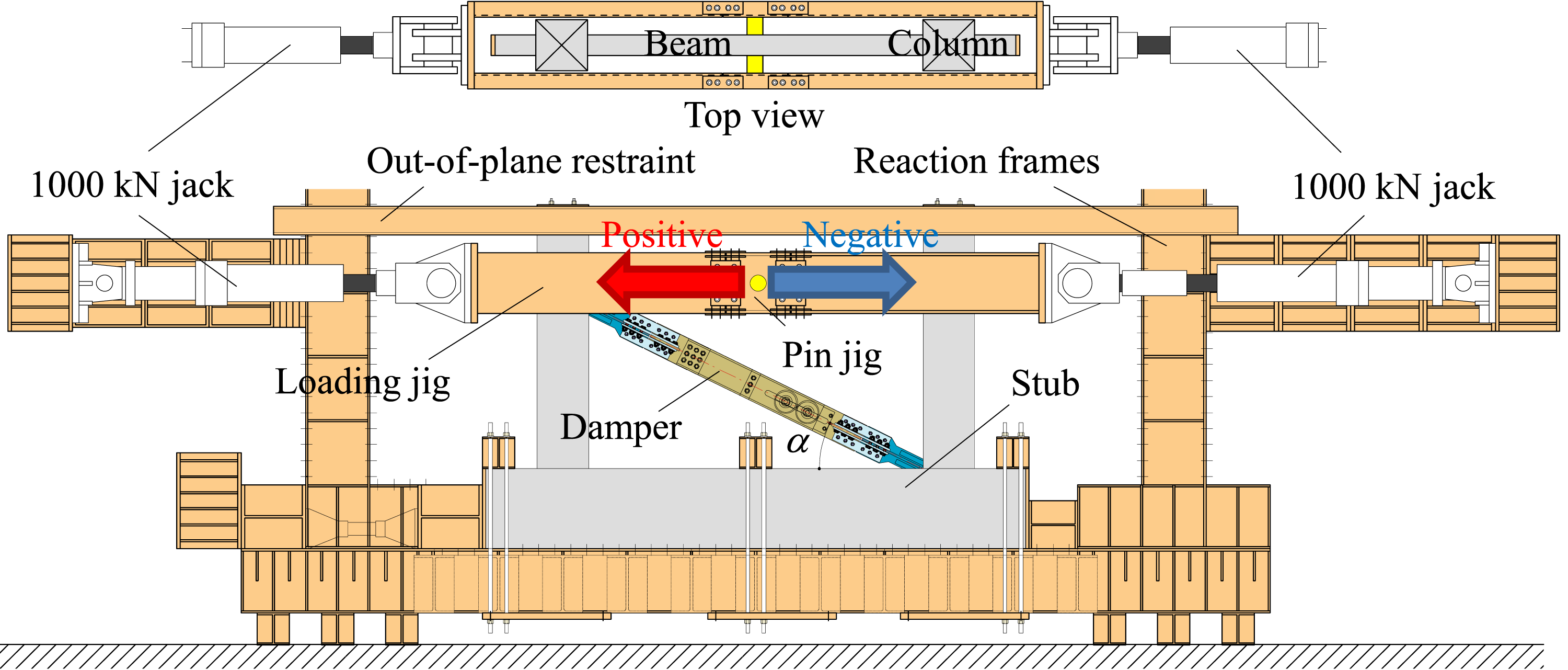
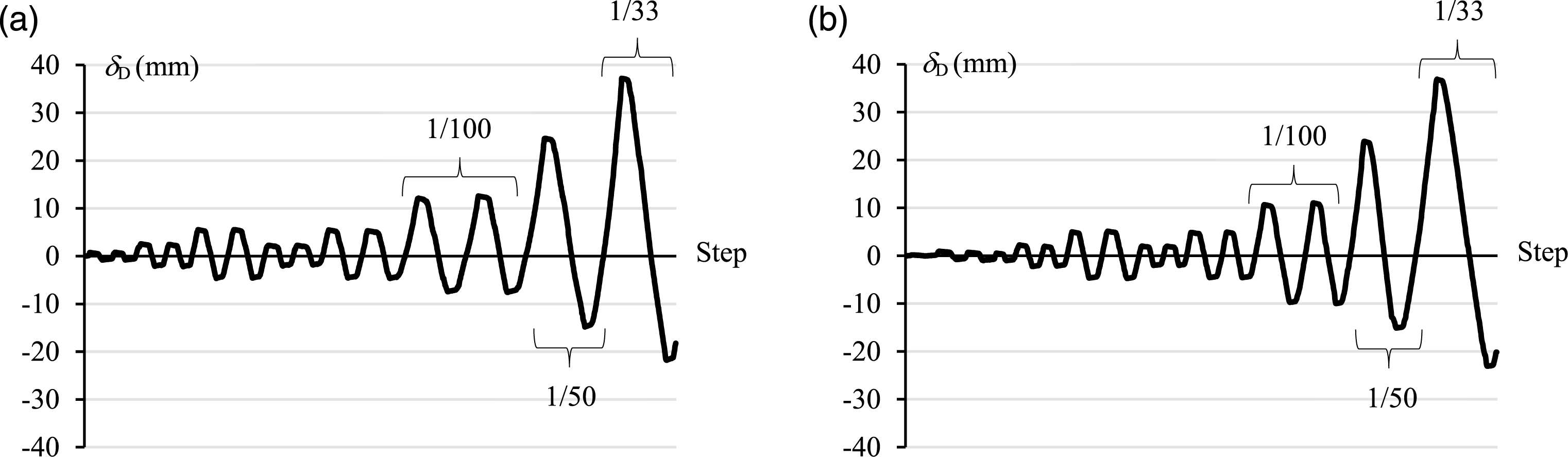
Figure 8 shows the loading protocol. Cyclic loading was conducted with increasing displacement amplitudes. Although it was a quasi-static cyclic loading test, the friction dampers are susceptible to loading rate which must be considered while designing the actual building. The horizontal force was applied via jacks that were connected on both sides of the reaction frame. During positive loading, the left jack in the figure was controlled to achieve tensile displacements, while the right jack maintained a zero load. During negative loading, the reverse force was applied. For each specimen, two cycles were conducted at the story drift ratio, with R amplitudes equal to 1/800, 1/400, 1/200, 1/400, 1/200, and 1/100 rad. Subsequently, only one cycle was conducted for amplitudes equal to 1/50 and 1/33 rad. Imposed displacement protocol.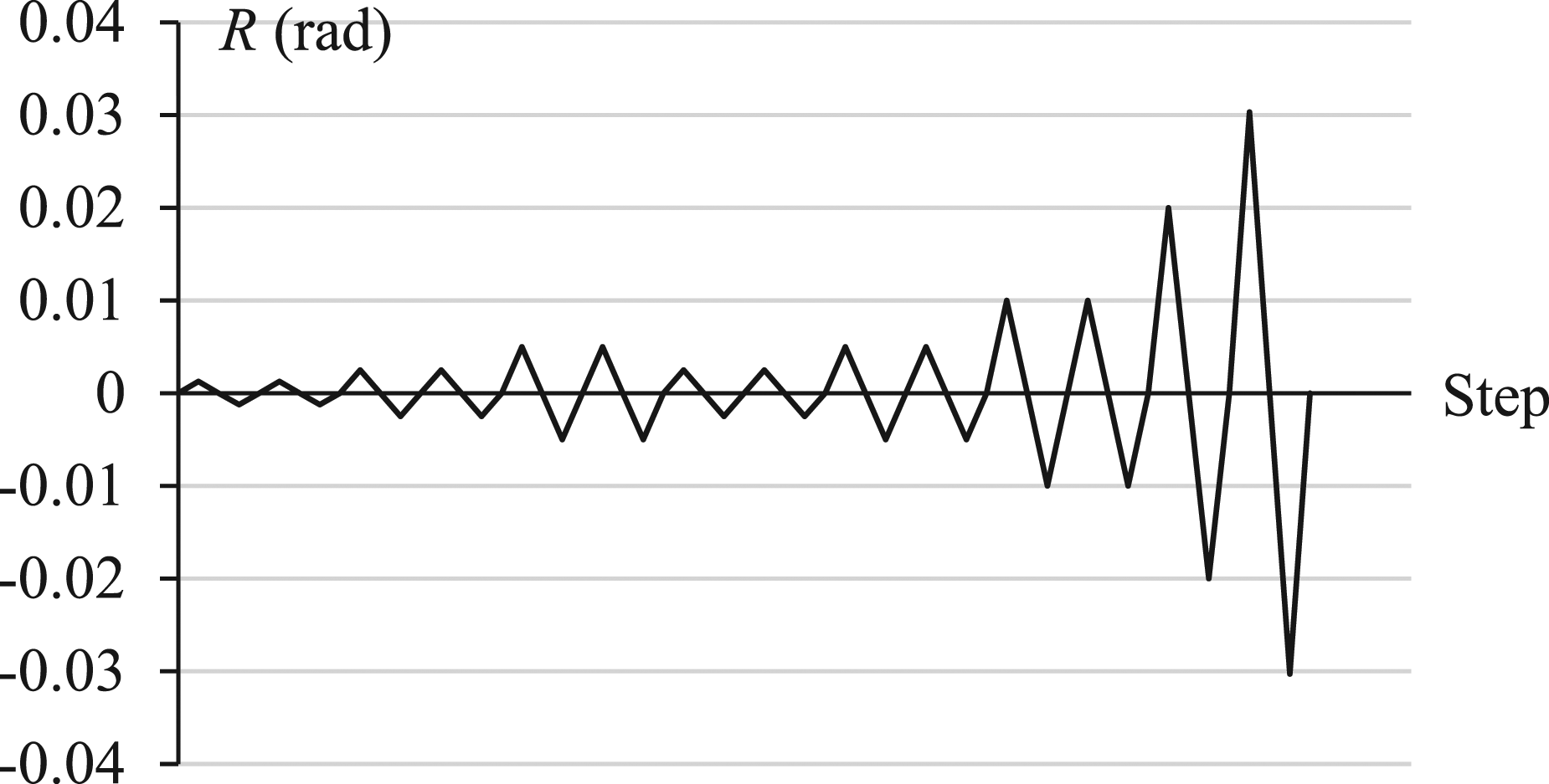
Figure 9 shows the displacement measurements. The story drift ratio, R, was obtained by dividing the average of the story deformation of the left and right columns by the distance between the upper surface of the stub and the beam core. The axial deformation of the beam was measured as the relative displacement near the centers of the beam and the column-joint panel, including the deformation of a part of the beam–column joint, as shown in Figure 9. The sliding displacement of damper δD (average of δDu and δDl) and the axial deformation of the damper connection δDC were measured as shown in Figure 9. Displacement measurements.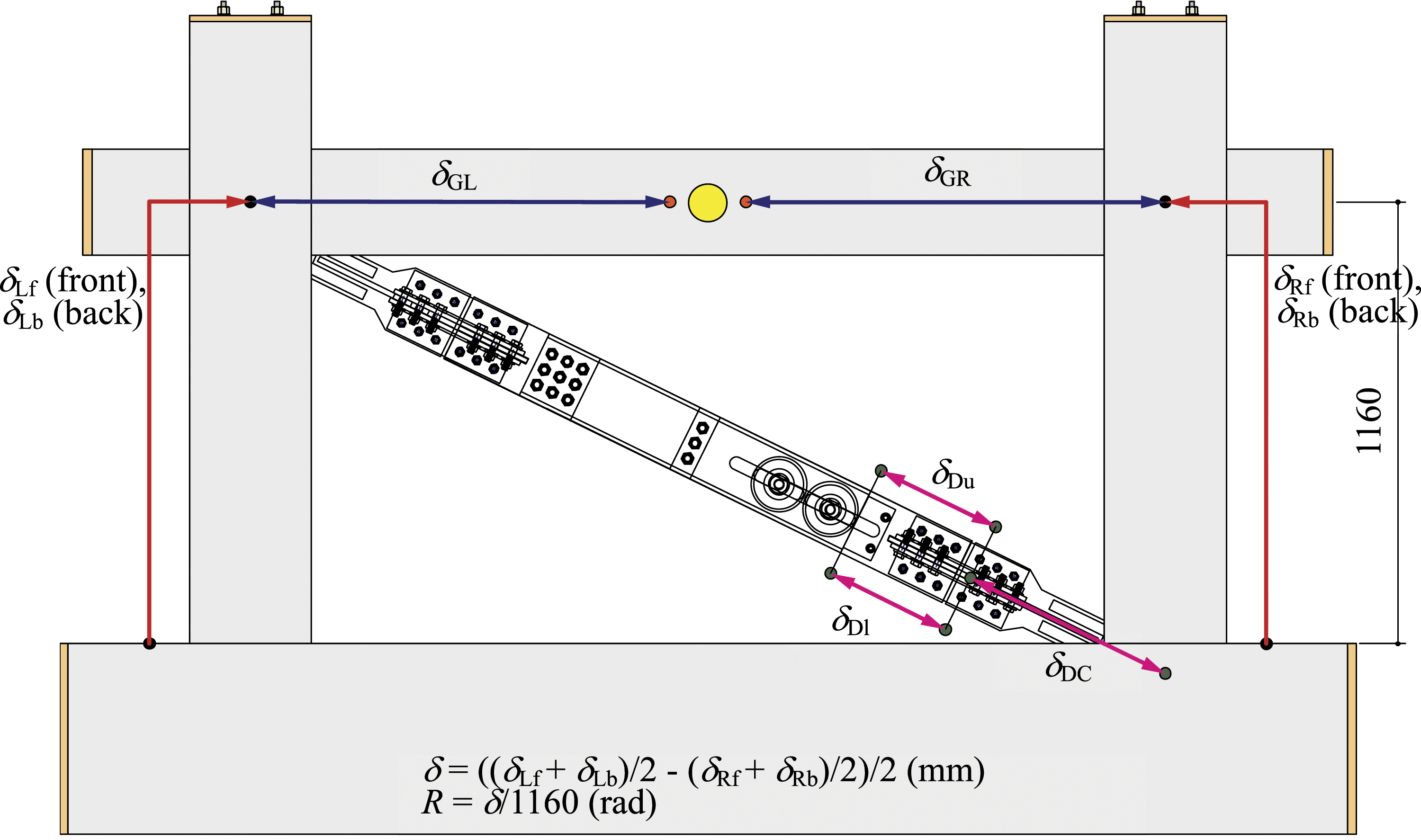
Tests results
Story drift versus shear force hysteretic loops
Figure 10 shows the relationship of the story drift ratio R versus the story shear force of the entire system QS which is represented by the jack load. For the specimens without dampers (CP-N, NP-N, and CD-N), QS is the story shear force of the RC frame QF only. For the specimens with dampers (NP-D and CD-D), QS is the sum of the story shear force of the RC frame QF and the horizontal component of the axial force of the damper QD. Therefore, for NP-D and CD-D, QS is shown separately for QF and QD. The axial force in the damper ND can be obtained from the value of the strain gauge attached to the elastic part of the outer steel channel. QF can be obtained by subtracting QD from QS. Plots of the story drift ratio R versus the story shear force Q: (a) CP-N, (b) NP-N, (c) CD-N, (d) NP-D, and (e) CD-D.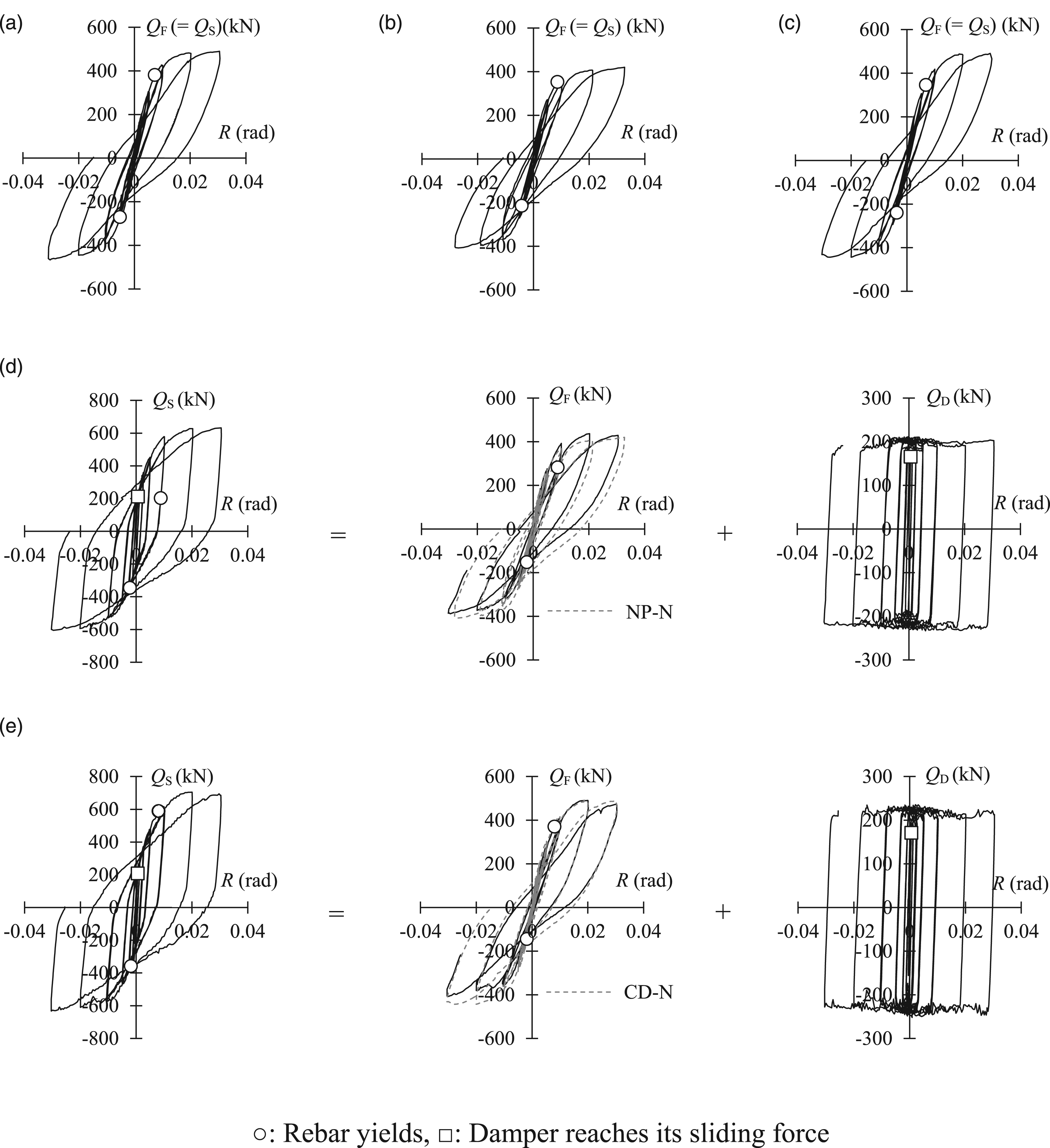
In the cases of CP-N, NP-N, and CD-N without dampers, all the specimens yielded stable hysteretic characteristics up to R = 1/33 rad. It was confirmed that a) the ultimate failure mode was flexural failure of the beam and that b) no brittle failure occurred. The maximum strength was 519 kN for CP-N, 421 kN for NP-N, and 490 kN for CD-N. NP-D with the damper having stable hysteretic characteristics up to R = 1/33 rad. The ultimate failure mode was the flexural failure of the beam. In CD-D, the story shear force was reduced at R = 1/50 rad cycle, but the axial force was still stable in the presence of the damper, while the rigidity of the RC frame slightly decreased on the negative load side. It was confirmed that the cause of the decrease in the story shear force after the test was the weld between the steel plate with the G.PL and the deformed bar near the beam–column joint.
For NP-D and CD-D, the damper reached its sliding force at 1/1473 and 1/1639 rad in each test, and the beam rebar yielded in each test at −1/445 and −1/536 rad. For the specimens of RC frames with dampers (NP-D and CD-D), it was confirmed that the damper reached its sliding force and started to dissipate energy at an early stage with smaller story drift ratios than those at RC beam yielding.
Energy dissipation capability
Figure 11 shows the cumulative hysteretic energy dissipation E at the end of the final cycle of each story drift ratio. At the end of R = 1/100 cycle, the dissipated energies were as follows: E = 572 kNm in CP-N, E = 440 kNm in NP-N, E = 481 kNm in CD-N, E = 950 kNm in NP-D, and E = 875 kNm in CD-D. In addition, at the end of R = 1/33 cycle, the dissipated energies were as follows: E = 1870 kNm in CP-N, E = 1618 kNm in NP-N, E = 2009 kNm in CD-N, E = 2829 kNm in NP-D, and E = 3010 kNm in CD-D. At the end of the 1/33 cycle, the dissipated energy of NP-D was 1.7 times that of NP-N, and CD-D was 1.5 times that of CD-N. It can be concluded from these results that the application of the damper in the RC frame can ensure a stable energy dissipation capacity. Cumulative hysteretic energy dissipation E.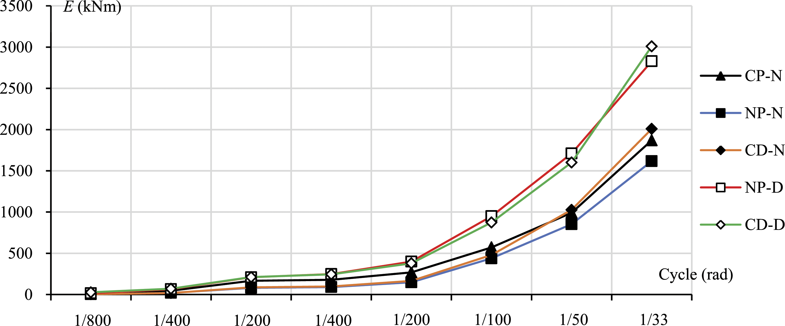
Damage to RC frames
Figure 12 shows the damages of the RC frames at R = ±1/100 rad. Damage of the RC frames at R = ±1/100 rad: (a) NP-N, (b) NP-D, (c) CD-N, and (e) CD-D.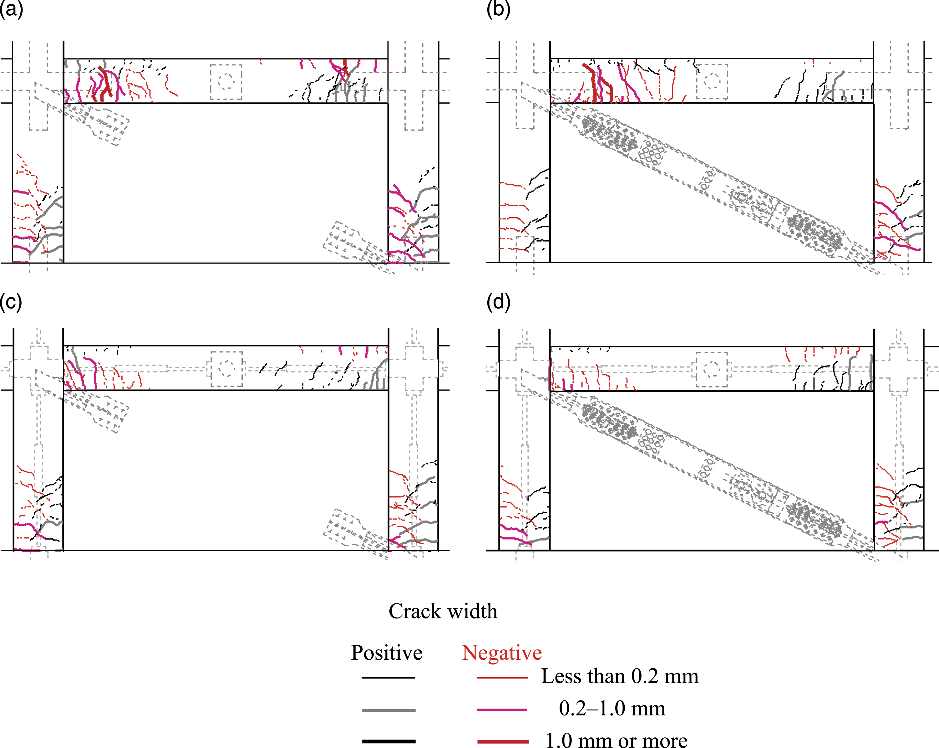
In all the specimens, flexural cracks in the beams and column bases were confirmed at R = 1/800 or 1/400 rad. No shear cracks occurred at the beam–column joint until the end of the test.
In the CD series, a largest crack was confirmed near the critical section in the beam, while in the NP series, a largest crack was confirmed at the position where the steel plate inside the beam was interrupted. The hinge position changed depending on the presence or absence of the internal steel member.
Behavior of the sliding part of the damper
Figure 13 shows the variation in the sliding displacement of damper δD versus the axial force in the damper ND. Figure 14 shows the transition of the sliding displacement of the damper δD. Variation in the sliding displacement of the damper δD versus the axial force in the damper ND: (a) NP-D and (b) CD-D. Transition of the sliding displacement of the damper δD: (a) NP-D and (b) CD-D.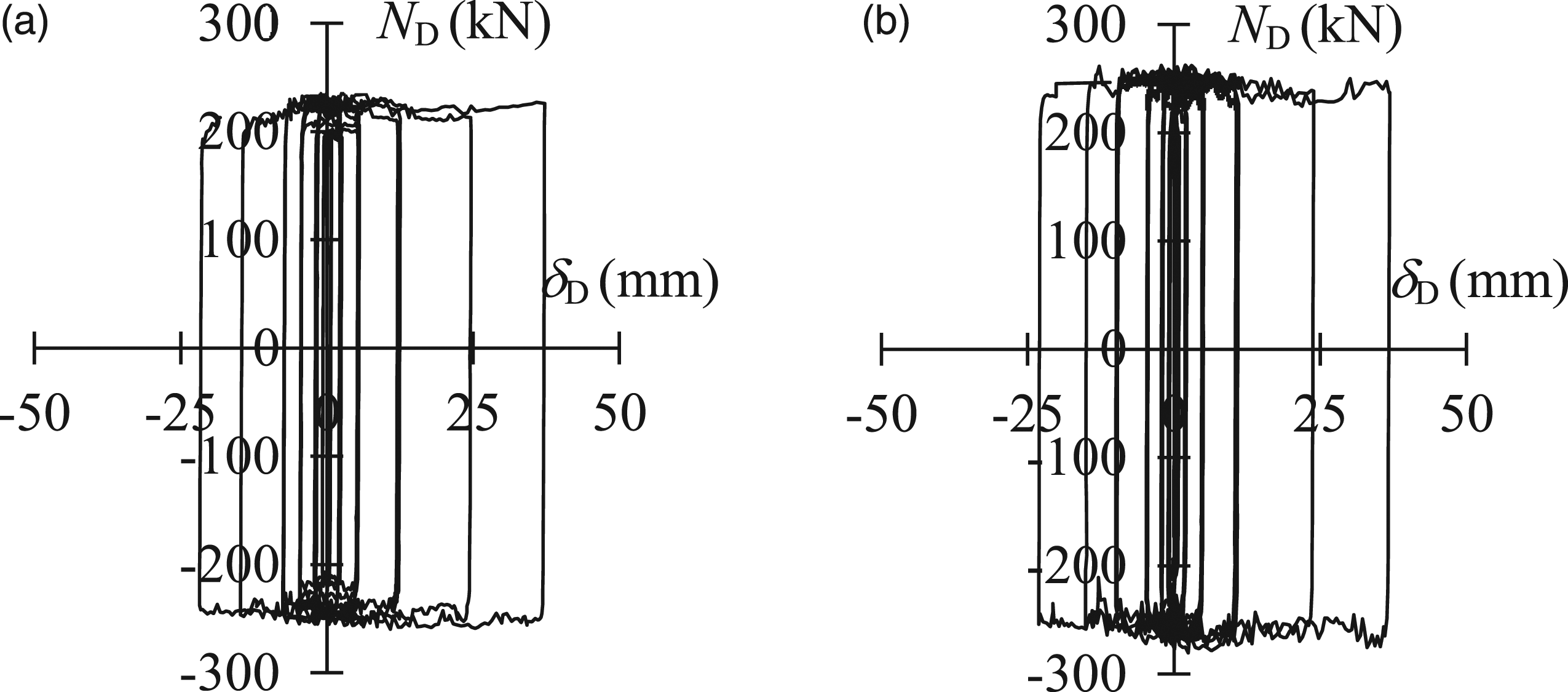
Based on the results in Figure 13, it can be concluded that the dampers of NP-D and CD-D were always sliding at the designed axial force of approximately 236 kN. Moreover, the damper exhibited stable hysteretic characteristics until the end of the test. However, the results in Figure 14 suggest that at the time of the large deformation of the R = 1/100, 1/50, 1/33 rad cycles, there was a difference in the sliding displacement of the damper between the tension and the compression sides. The reason for this is thought to be the tensile axial force acting on the left side of the RC beam when the damper is compressed, causing large cracks in the concrete and reducing the effective deformation of the damper.
Axial deformation of the beam
Figure 15 shows the variation in the axial deformation on the left side of beam δGL versus the story shear force QF. The specimen without the damper undergoes the deformation until the end of the tests (Figure 15(a)). The results up to R = 1/100 rad are shown (Figure 15(b)) in the case of the specimen with the damper. After R = 1/100 rad, the measuring instrument failed. Plot of the axial deformation on the left side of the beam δGL as a function of the story shear force: (a) specimens without damper and (b) specimens with damper.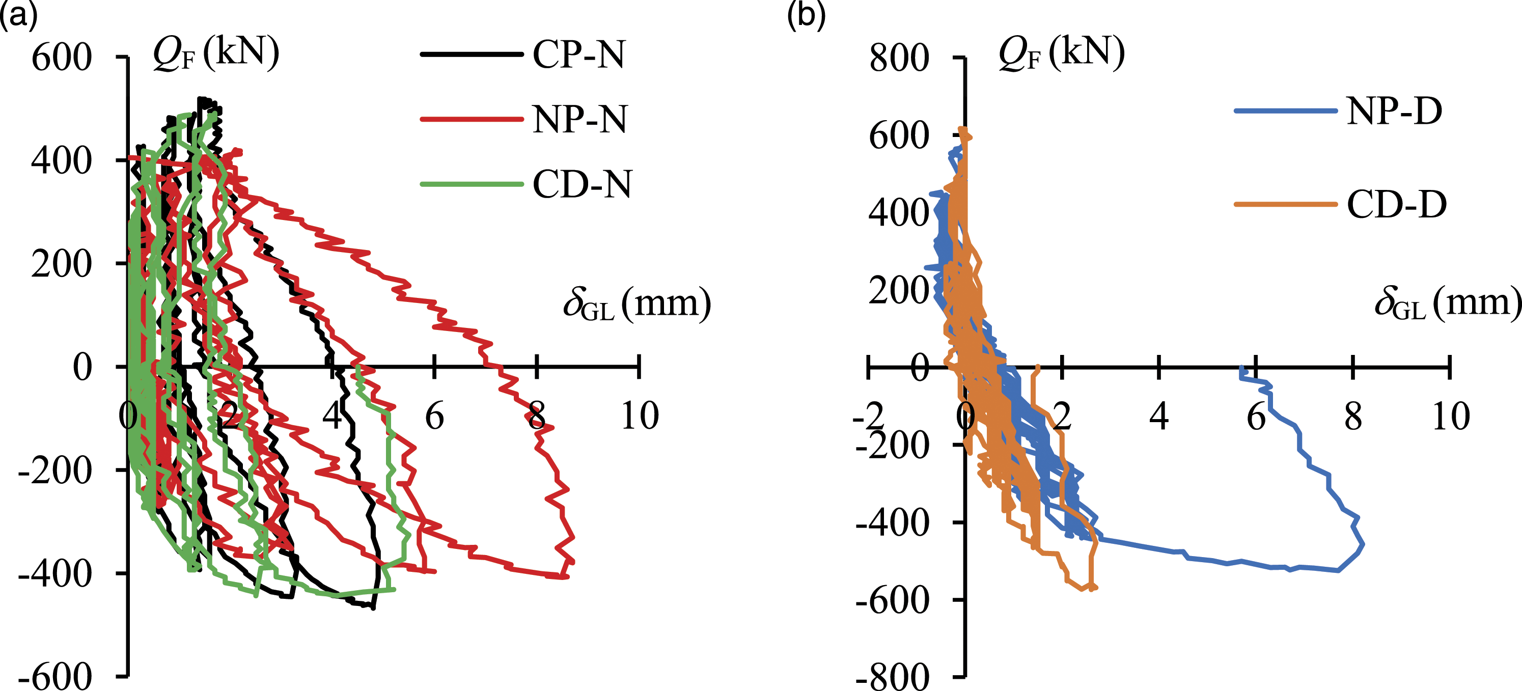
In the specimens without dampers, the axial deformation on the left side of the beam was approximately 5 mm (at most) for CP-N and CD-N while it was >8 mm in the NP-N test specimen. In the specimens without dampers, the axial force was generated in the beam due to the application of a load at the beam center, but it was confirmed that the axial deformation of the beam could be suppressed if a steel member was installed inside the beam.
In the specimens with the dampers, the axial deformation of the beam was approximately 8 mm at R = 1/100 rad cycle for NP-D, and approximately 2 mm for CD-D which is smaller compared to NP-D.
The axial deformation on the left side of beam δGL and the sliding displacement of damper δD in CD-D are considered. In Figure 16, the vertical axis shows the axial force in the damper ND, and the horizontal axis shows the axial deformation on the left side of the beam δGL and the sliding displacement of the damper δD in CD-D. The bold line represents the cycle that corresponds to R = −1/50 rad. When the deformed bar inside the beam broke and the axial deformation of the beam increased, the sliding displacement of the damper decreased. This suggests that passing a deformed bar through the beam is an effective way to secure a stable damper sliding displacement. After the tests, the concrete of the beam was cut to check the condition of the deformed bar inside it as shown in Figure 17. The welded part of steel plate PL-25 used for joining with G.PL and the deformed bar were broken. Improvement in the strength of this joint needs further examination. Plot of the axial deformation of the beam δGL and the sliding displacement of the damper δD. Condition of the deformed bar after the tests: (a) part of the concrete of the beam was cut and (b) welded part.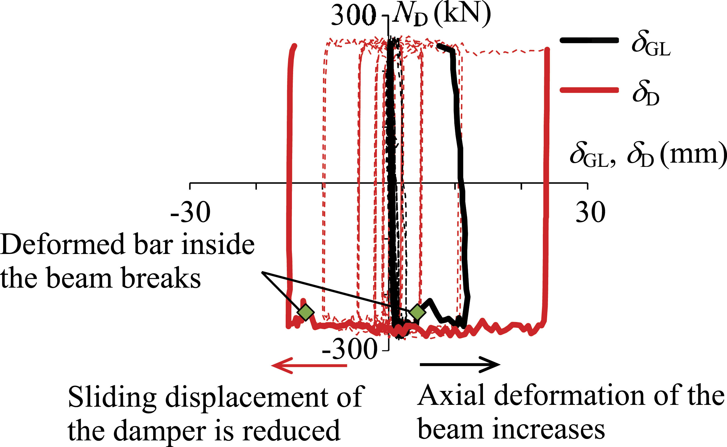

Axial deformation of the beam and the damper connection for each load condition
Regarding the axial force in the damper at the R = −1/100 rad cycle, the behaviors in each state of the transition from tension to compression (thick black line)—including the constant compression (thick red line)—and the transition from compression to tension (thick blue line) are considered, as shown in Figure 18 (State of the load). The vertical axis in Figure 18 shows the shear force of the RC frame QF in the left parts of the diagram and the damper in the axial force ND in the right parts. Axial deformation of the beam δGL and the axial deformation of the damper connection δDC for each load condition: (a) NP-D and (b) CD-D.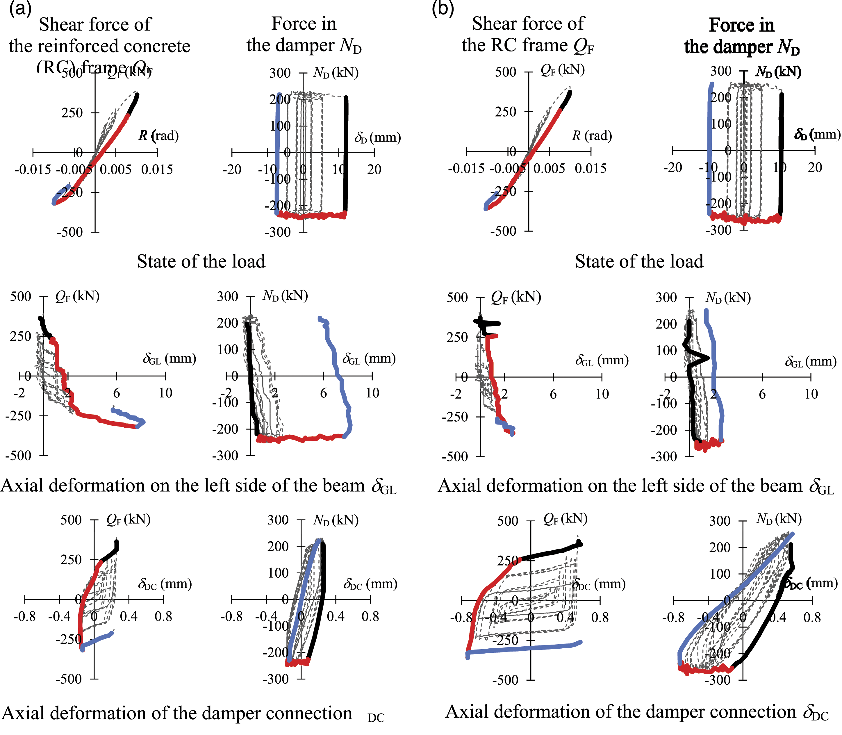
The sliding displacements of the damper were −7.5 mm and −9.7 mm for NP-D and CD-D, respectively, at the peak of R = −1/100 rad, as indicated in the plot of the sliding displacement of the damper δD versus the damper’s axial force ND in Figure 18 (State of the load). By installing the deformed bar inside the beam, a stable sliding displacement was secured for the damper.
Figure 18(δGL) shows the axial deformation on the left side of beam δGL. In NP-D, the axial deformation on the left side of beam δGL is approximately 2 mm during the elastic range. When the beam yields, it increases to ∼8 mm at the peak of the R = −1/100 rad cycle. However, in CD-D, even after the beam yields, the axial deformation on the left side of beam δGL is suppressed to approximately 2 mm even at the peak of R owing to the presence of the deformed bar inside the beam.
Figure 18(δDC) shows the axial deformation of the damper connection δDC, which changed in all the specimens when the damper axial forces shifted. This indicates that the influence of the shear force of the RC frame QF is minor. The maxima of the axial deformation of the damper connection δDC occured at ∼0.2 mm in NP-D and at ∼0.75 mm in CD-D up to the R = −1/100 rad cycle. The axial deformation of the damper connection is slightly larger in CD-D than in NP-D, but it is suppressed to values less than 1 mm in all the test specimens, and its effect on the behavior of the damper is minor.
Conclusions
In this study, the structural behaviors of RC frames with brace-type friction dampers were studied by cyclic horizontal loading tests. The major findings are summarized below. (1) The methods of embedding the G.PL with stud bolts near the beam–column joint and the insertion of the deformed bar through the RC member were effective for damper connections in the RC frames. (2) For the RC frame specimens with dampers (NP-D and CD-D), it was confirmed that the damper attained the sliding force and started to dissipate energy at an early stage with story drift ratios that were minor in comparison to those at RC beam yielding. In addition, at the end of the 1/33 cycle, the dissipated energy of NP-D was 1.7 times that of NP-N (without the damper), and the CD-D was 1.5 times that of CD-N (without the damper). These results suggest that the application of the damper in the RC frame can ensure a stable energy dissipation capacity. (3) In the test, the welded part of steel plate PL-25 for joining with G.PL and the deformed bar were broken for CD-D. When the welded part inside the beam broke and the axial deformation of the beam increased, the sliding displacement of the damper decreased. Therefore, a reliable jointing method needs to be established in future.
An analytical model needs to be developed to practically apply the proposed system. Currently, the test results can be well reproduced with a finite element model (Maida and Sakata, 2020). Furthermore, the simple analysis model required for the design of the actual building has not been developed. This constitutes a vision for future studies on this topic.
Footnotes
Declaration of conflicting interests
The author(s) declared no potential conflicts of interest with respect to the research, authorship, and/or publication of this article.
Funding
The author(s) disclosed receipt of the following financial support for the research, authorship, and/or publication of this article: This work was supported by the Japan Society for the Promotion of Science grant number 23246098.