
Abstract
The utilization of fiber-reinforced polymer (FRP) reinforcements in structural design is increasing due to their non-corrosive nature. However, the anisotropic features and linear elastic behavior of FRP rebars have led researchers to explore the use of hybrid combinations of FRP and steel reinforcements. Current codes and guidelines predominantly focus on the design of glass FRP (GFRP) reinforced structural elements, leaving a gap in incorporating the hybrid use of FRP-steel combinations and different types of FRP materials, such as carbon FRP (CFRP). This study conducted experimental investigations on concrete beams reinforced with GFRP, CFRP, and hybrid (GFRP-steel and CFRP-steel in combination) rebars, comparing the results with theoretical models. Ten full-scale beams were tested under monotonic loading. Test results revealed that existing codes overestimate GFRP reinforced beam displacements while underestimating CFRP reinforced beam displacements. A reduction factor is proposed for the effective moment of inertia expression given by ACI 440.11-22 to predict the deflections of CFRP reinforced and hybrid reinforced beams. The experimental data for CFRP and hybrid reinforced concrete beams align well with the predictions calculated using the proposed equations.
Keywords
Highlights
• Modified I
e
equation is proposed for CFRP and hybrid (FRP-steel) RC beams • Ten full-scale beam specimens are tested under the three-point bending test • Detailed flexural behavior of the experimental and analytical results is presented • Codes and guidelines underestimate the midspan displacements of CFRP-RC beams • Hybrid FRP-steel rebar configuration introduces nonlinearity in load-displacement curve
Introduction
In the last decades, fiber-reinforced polymer (FRP) bars have been a promising alternative to conventional steel rebars due to their better corrosion resistance, high tensile strength-weight ratio, and nonmagnetic nature (ACI 440.1R, 2015). Replacing conventional steel with FRP rebars has been investigated thoroughly (Aiello and Ombres, 2000; Alsayed et al., 2000; Benmokrane et al., 1995; El-Gamal et al., 2011; El-Nemr et al., 2013; El-Sayed et al., 2006; Esmaeili et al., 2020; Junaid et al., 2019; Liang et al., 2023; Ramachandra Murthy et al., 2020; Sarhan and Al-Zwainy, 2022) and several countries and regions developed design guides for FRP reinforced concrete structures, such as Japan (JPCI, 2021; JSCE, 1997), Europe (Fib, 2007, fib, 2023), Canada (CSA 2012; ISIS 2007), and America (ACI 440.1R 2015; ACI 440.11 2022). However, the wide range utilization of FRP reinforcements, particularly as a longitudinal reinforcement, has been rather limited due to their two main drawbacks: linear elastic behavior until rupture and low elasticity modulus. Although the non-corrosive nature of the FRP improves the durability of the reinforced concrete structures, FRP rebars attain their full tensile strength without yielding or hardening, which reduces the ductility of FRP reinforced concrete structures and limits their inelastic behavior (Bencardino et al., 2016; El Refai et al., 2015; Wang and Belarbi, 2011). Therefore, ACI 440.1R-15 (2015) and CSA S806-12 (2012) suggest an over-reinforced design for the glass-FRP (GFRP) reinforced beams to enable the concrete failure before GFRP rupture. Moreover, due to the low elasticity modulus of most commercially available FRP rebars, FRP reinforced concrete beams exhibit larger deflections and wider cracks compared to those reinforced with steel rebars (El-Gamal et al., 2011). To maximize the structural behavior of FRP reinforced concrete beams, researchers proposed methods such as hybridization of different fibrous materials (Elsayed et al., 2011; Harris et al., 1998; Tepfers et al., 1996) or compounding FRP bundles over steel rods (Nanni et al., 1994a, 1994b; Said et al., 2021; Yang et al., 2020). However, application of these proposed hybrid rebars are not widely adopted due to the high complexity in the manufacture process. Some of the relatively practical solutions to improve flexural behavior in terms of ductility and controlling deformability of the FRP reinforced beams are addition of fibers to concrete (Alsayed and Alhozaimy, 1999; Issa et al., 2011; Li and Wang, 2002; Patil et al., 2020; Wang and Belarbi, 2011; Zhu et al., 2018) and using FRP rebars and steel reinforcements in combination (Aiello and Ombres, 2002). With such a hybrid system, steel reinforcement increases the ductility of the beam, while FRP reinforcement maintains the flexural load-carrying capacity (El Refai et al., 2015). Moreover, steel rebars reduce the deformability by decreasing the deformations and crack widths when compared to pure FRP reinforced concrete beams (Aiello and Ombres, 2002).
The hybrid usage of steel and FRP reinforcement has been utilized in recent designs. Qu et al. (2009), Lau and Pam (2010), and Refai et al. (2015) conducted experiments on hybrid (GFRP-steel) reinforced beams, showing that steel reinforcements improved the flexural behavior in terms of ductility and stiffness, as steel has higher stiffness and steel rebars yield before concrete crushing. In addition, Refai et al. (2015) showed that the over-reinforced hybrid beams outperformed their GFRP reinforced counterparts in terms of strength and ductility. Experimental studies on BFRP-steel reinforced beams highlighted the effect of steel reinforcement addition on deformability of the hybrid beams. Ge et al. (2015) found that hybrid (BFRP-steel) reinforced beams exhibited deflection and crack spacing values between those of steel and FRP reinforced beams. Steel-reinforced beams had the least deflection and crack spacing, while FRP-reinforced beams had the most. Akiel et al. (2018) showed that hybrid reinforcement improved the serviceability of the beams with less deflections and smaller crack widths at service load than their counterparts reinforced with BFRP rebars only. Ruan et al. (2020) studied the flexural behavior of GFRP-steel reinforced concrete beams. The ultimate flexural capacity of the hybrid reinforced beam was found to be 5% less (on average) than that of the steel reinforced counterparts. Authors proposed a modification to effective moment of inertia expression given by ACI 440.1R-15 for the prediction of deflections of hybrid reinforced beams.
Another important aspect of hybrid reinforced concrete beams is the ratio between steel and FRP reinforcement. Nguyen et al. (2020a) and Abbas et al. (2022) studied the effect of reinforcement ratios and configurations on the flexural behavior of GFRP and hybrid (GFRP-steel) reinforced concrete beams. Nguyen et al. (2020b) showed that GFRP presence delays the steel yielding with a linear relationship between GFRP reinforcement ratio and steel yielding load. In addition, for the same reinforcement ratios, increasing GFRP reinforcement ratio improves the load-carrying capacity of the hybrid reinforced beams. Abbas et al. (2022) investigated under-reinforced hybrid beams (GFRP-steel) with steel reinforcement ratios to GFRP rebars, varying from 0.5 to 2, showing that the ductility of hybrid reinforced concrete beams increased almost linearly with the increase of the steel ratio. Pang et al. (2016) suggested reinforcement ratio limits to ensure ductile failure of the hybrid reinforced beams and introduced a new ductility index based on deformability and energy absorption capacity. These studies highlight the importance of the balance between the steel and GFRP reinforcement areas on attaining the desired strength and ductility. The effect of the bond-slip relation between the GFRP rebars and concrete (Xingyu et al., 2020) and the effect of bundling on the flexural behavior of hybrid reinforced beams (Sun et al., 2019) are other important aspects for design of hybrid reinforced beams.
Numerical studies on hybrid reinforced beams proposed models for predicting the flexural behavior of hybrid reinforced concrete beams (Bencardino et al., 2016; Kara et al., 2015). However, some numerical models are only suitable for the beams with low and normal reinforcement ratios (Bencardino et al., 2016). Kara et al. (2015) showed that the FRP reinforcement played an important role in the load-carrying capacity of the beams after steel yielding in over-reinforced sections in their parametric study. Kheyroddin and Maleki (2017) proposed a new equation based on the genetic algorithm to estimate the effective moment of inertia of hybrid (FRP-steel) reinforced concrete beams. Mustafa and Hassan (2018) conducted a numerical study using nonlinear finite element analysis on hybrid (GFRP-steel and CFRP-steel) reinforced concrete beams. The authors stated that hybrid CFRP-steel reinforced beams outperformed their GFRP-steel counterparts during crack initiation and propagation. Peng et al. (2023) proposed reliability-based design provisions for hybrid (FRP-steel) reinforced concrete beams.
Existing research demonstrates a wide range of applications of hybrid reinforced concrete beams and various types of FRP rebars. However, current codes and guidelines primarily focus on GFRP rebars, and there is a need to update these regulations to include the hybrid use of FRP-steel combinations and different types of FRP rebars. In pursuit of this goal, this study investigates the flexural performance of hybrid reinforced concrete beams with different FRP rebars, focusing on the effect of FRP type, and FRP rebar size on the deflection and the deformability of the beams. Ten full-scale FRP reinforced concrete beams are tested and the test results of the specimens are presented with the load-displacement curves, failure modes, crack patterns, and concrete strain curves. Experimental results are compared and discussed in detail with the American and Canadian codes and design guidelines and numerical methods proposed by researchers. The novelty of this study lies in proposing a reduction factor for application with the effective moment of inertia expression provided by ACI 440.11-22 (2022) to predict the deflections of CFRP reinforced and hybrid (GFRP-steel and CFRP-steel) reinforced beams.
Experimental program
Test specimens
Details of test specimens.
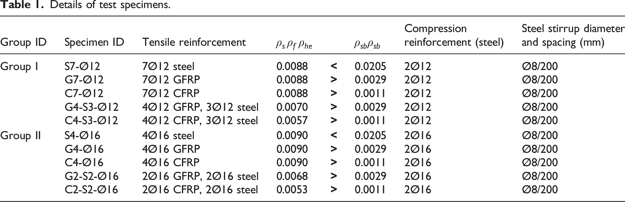
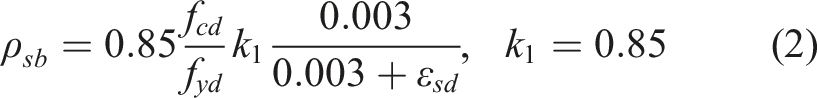
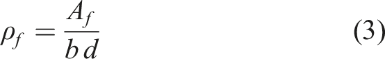
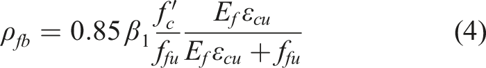
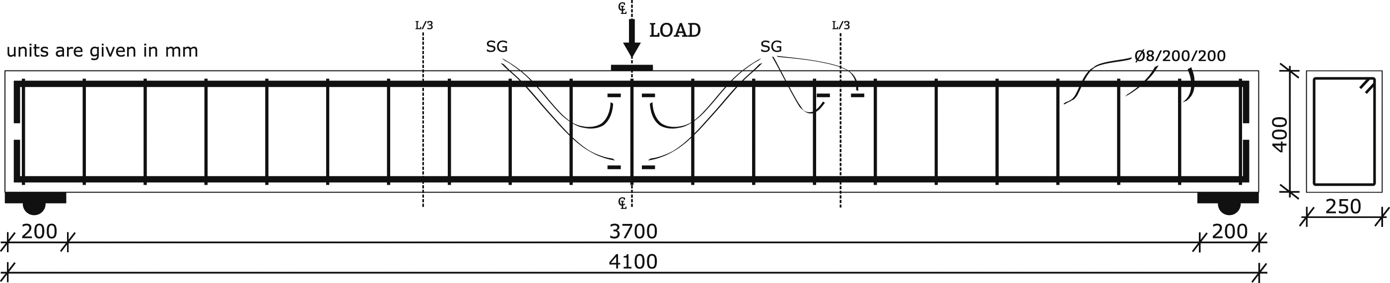
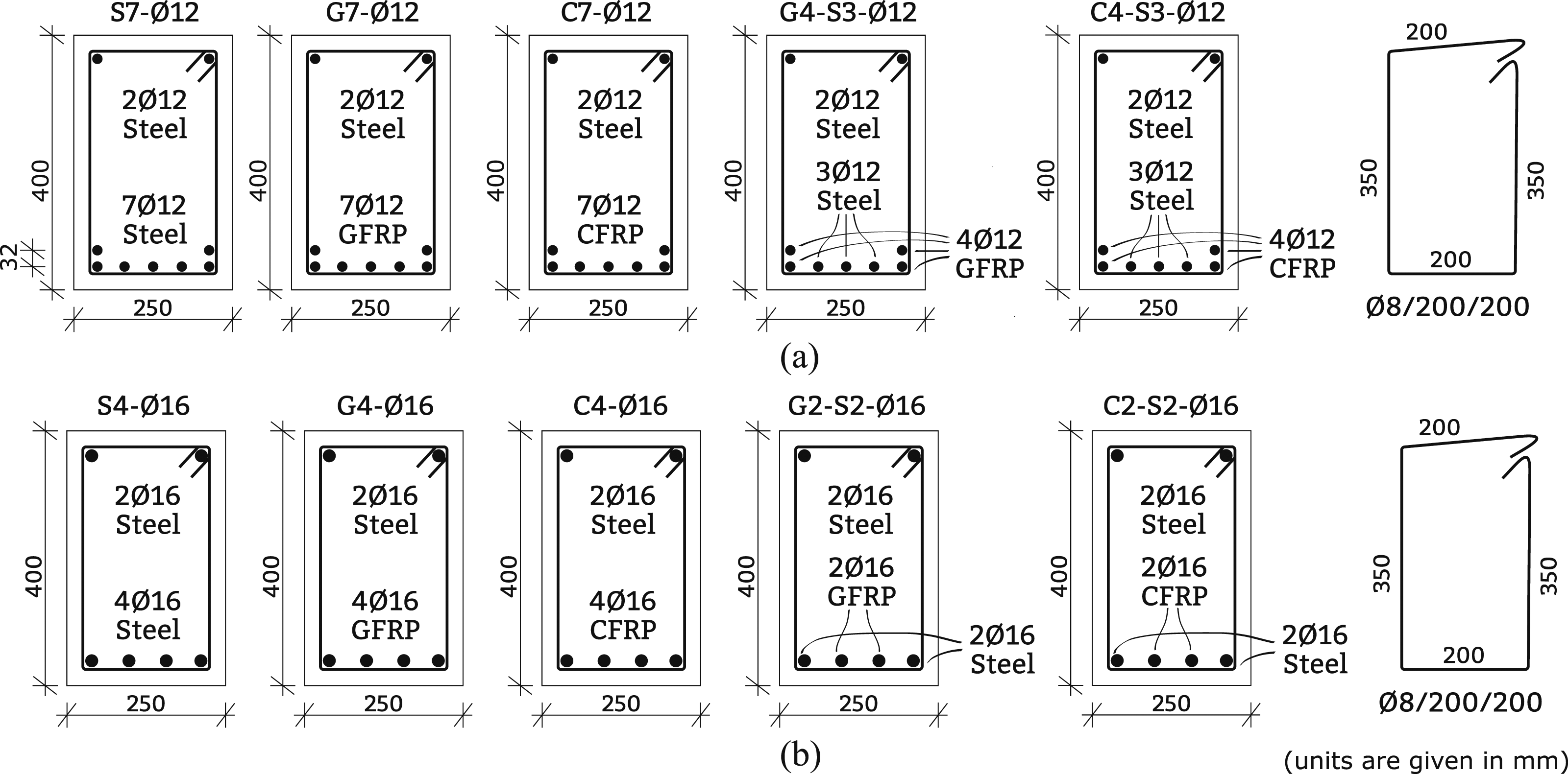
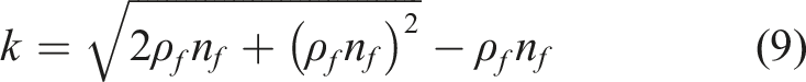
Figure 1 shows the dimensions of the specimens. The width and height of the rectangular section and the length of the beam were selected as 250 mm, 400 mm, and 4100 mm, respectively. Cross-section details of Group I and Group II are shown in Figure 2. All specimens were built as over-balanced except the S7-Ø12 and S4-Ø16. ACI 318-19 (2019) (Equation (1) and equation (2)) and ACI 440.1R-15 (2015) (Equation (3) and equation (4)) guides were used for the calculation of balanced reinforcement ratios of steel-reinforced beams and FRP reinforced beams, respectively. Balanced reinforcement ratio for steel and FRP reinforced beams were calculated using equation (2) for Beam test setup. (a) Reinforcement details of Group I and (b) Group II specimens.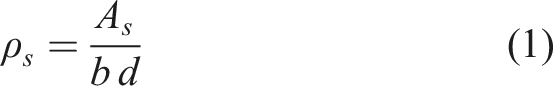
Materials
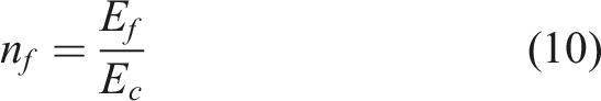
Sand-coated GFRP and CFRP rebars were used as tensile reinforcement. An image of GFRP, CFRP, and steel reinforcements with a nominal diameter of 12 mm and 16 mm is given in Figure 3. Reinforcements used in specimens.
Mechanical properties of GFRP, CFRP, and steel reinforcements.
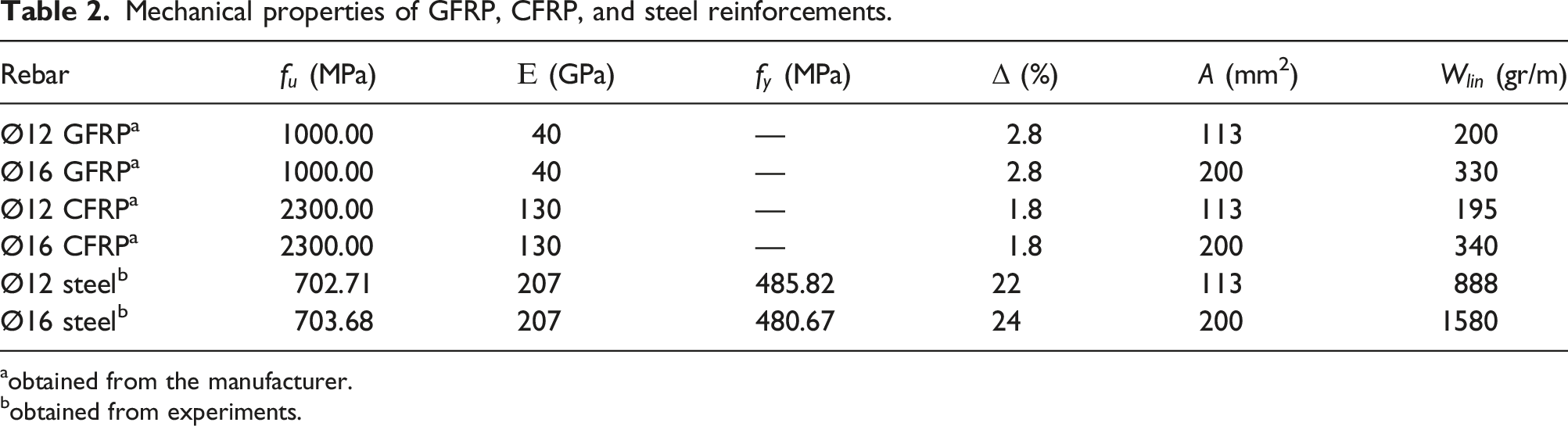
aobtained from the manufacturer.
bobtained from experiments.
All specimens were cast on the same day in one batch with normal-weight, ready-mix concrete with specified compressive strength of 25 MPa after 28 days. A concrete admixture with a superplasticizer was used to increase the workability and strength of concrete. Concrete compressive strength was tested on the 7th, 28th and on the test day (120th day on average). The average compressive strength of standard 150 mm × 150 mm x 150 mm cubic specimens tested according to TS EN 206+A2 (2021) on the test days were found as 34.6 MPa ±2.2 MPa, achieving the targeted equivalent cylinder compressive strength of 28.0 MPa.
Test setup
Beam specimens were investigated under a three-point bending test. Figure 1 illustrates the test setup. The middle span displacement was measured with a potentiometric position sensor. The concrete strain at Mapping of crack patterns of specimens.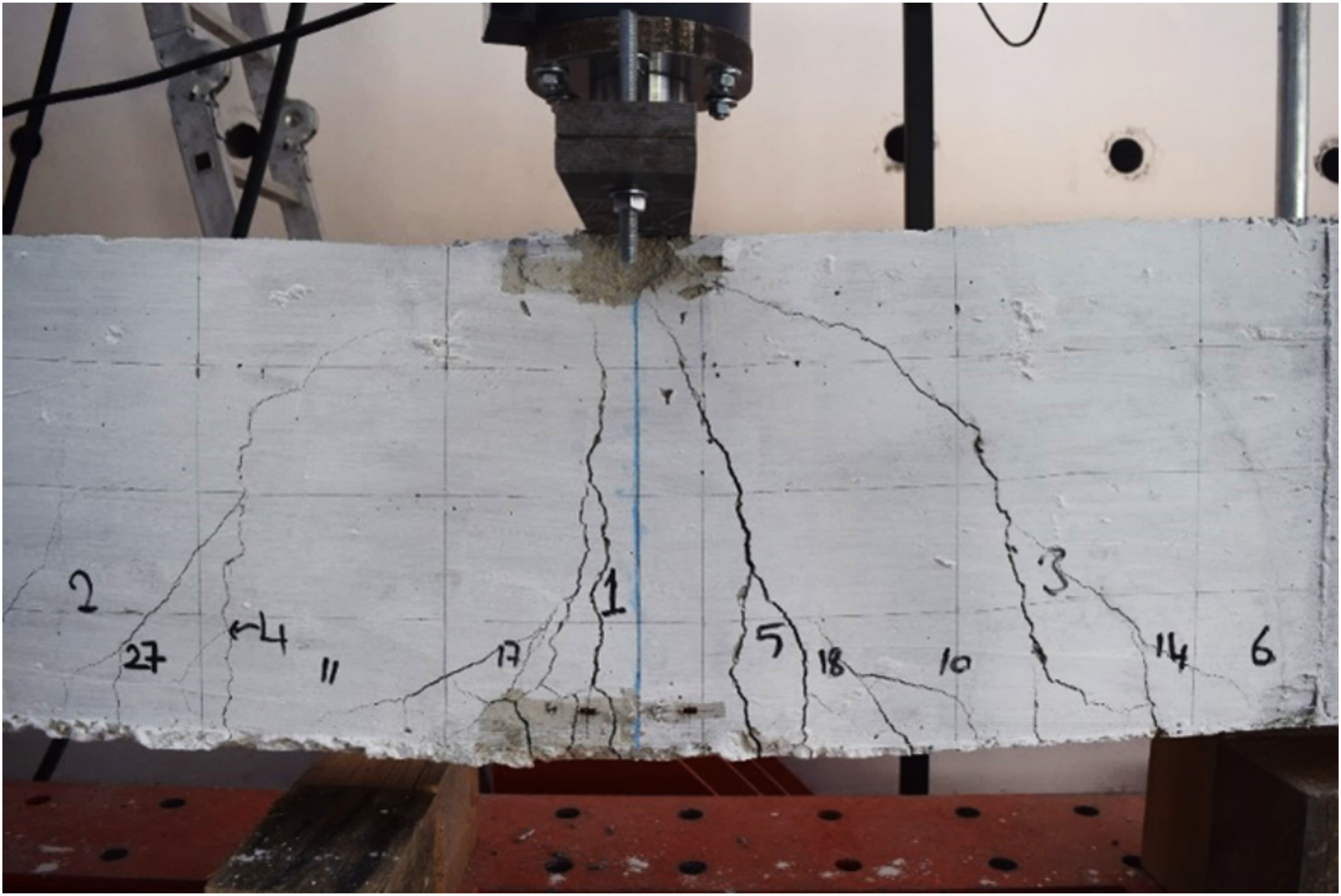
Test results
Initial cracking load, ultimate load and failure modes of specimens.
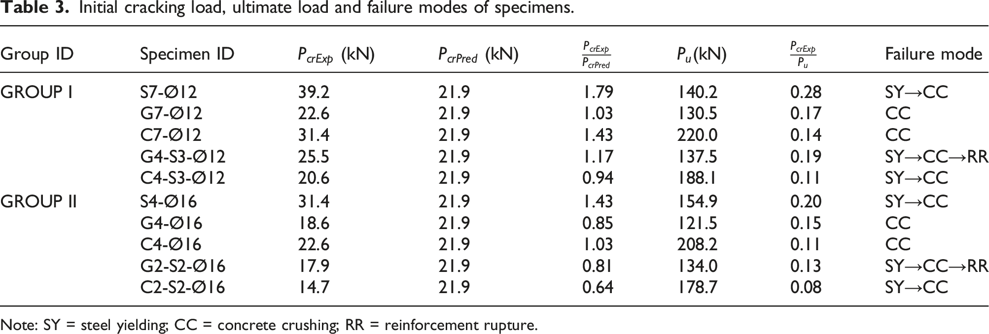
Note: SY = steel yielding; CC = concrete crushing; RR = reinforcement rupture.
Displacements at the Midspan of Specimens.
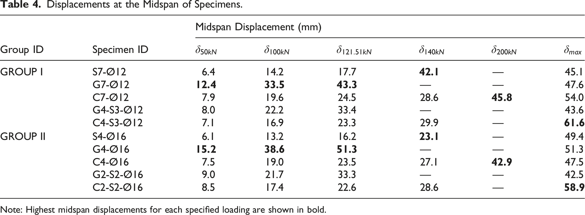
Note: Highest midspan displacements for each specified loading are shown in bold.
Table 4 shows the midspan displacements of the specimens at different arbitrary intermediate load levels (50 kN, 100 kN).
General behavior and failure modes
The results of the experiments along with the observed failure modes are presented in Table 3. Failure modes are denoted as CC (Concrete Crushing), RR (Reinforcement Rupture), and SY (Steel Yielding). These failure modes are listed in the order of their occurrence in the experiments. For specimens solely reinforced with steel rebars (Steel-RC), the sequence of failure modes was SY followed by CC. In contrast, for specimens reinforced exclusively with GFRP (GFRP-RC) and CFRP (CFRP-RC), concrete crushing (CC) was the initial failure mode, consistent with the guidelines outlined in building codes (ACI 440.1R 2015; ACI 318 2019; CSA S806 2012). Both GFRP-RC and CFRP-RC beams ultimately failed due to concrete crushing (CC) (Figure 5). Concrete crushing.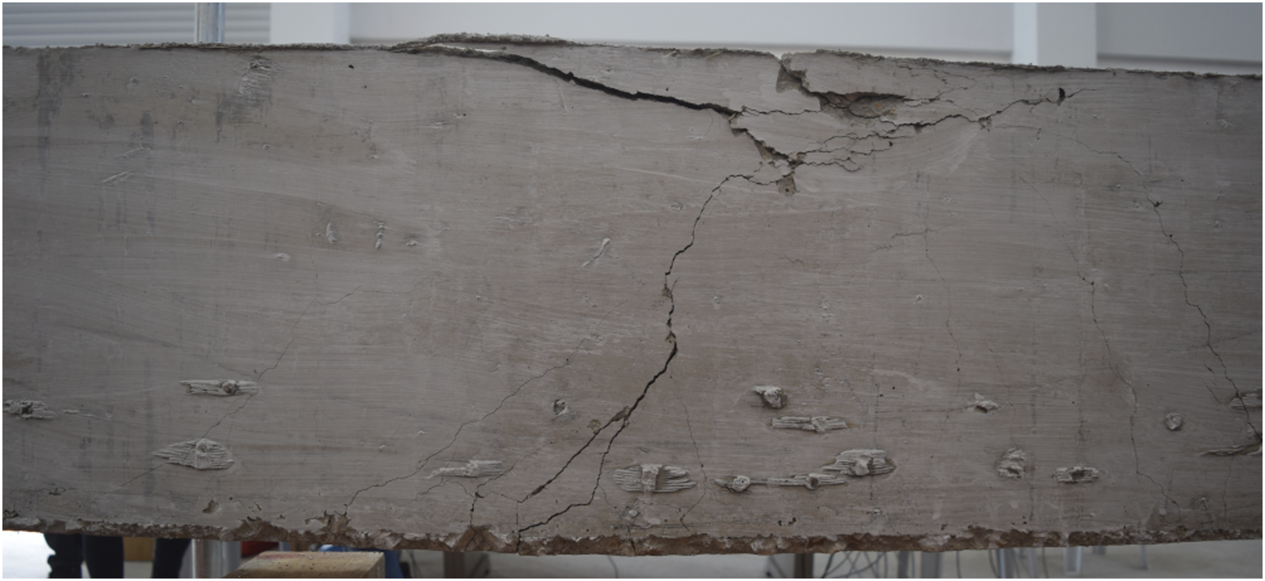
In the case of hybrid specimens, SY occurred before CC, followed by RR for GFRP-steel hybrid reinforced beams. A notable observation is that replacing up to 50% of the tensile reinforcement with steel rebars altered the failure mode, causing steel yielding to precede concrete crushing in both GFRP-RC and CFRP-RC specimens. Comparing Group I and Group II specimens, which had different rebar diameters, no significant change in the failure modes was observed. The distinct failure modes observed in the experiments were the result of the different mechanical properties of the rebar materials.
Load-carrying capacity
As anticipated, CFRP-RC beams outperformed GFRP-RC and Steel-RC beams in terms of ultimate load-carrying capacity, primarily due to the significantly higher tensile strength of CFRP, which is 1.30 and 2.27 times greater than that of GFRP and steel, respectively. At the ultimate load levels, hybrid CFRP-steel reinforced beams exhibited the highest midspan displacements. While GFRP-RC beams exhibited the lowest load-carrying capacity, they displayed higher displacements at the same load levels, attributed to their lower flexural stiffness. Comparing hybrid CFRP-steel reinforced specimens to their Steel-RC counterparts, it was observed that steel reinforcement contributed to increased displacement capacity, while CFRP reinforcement improved load-carrying capacity.
According to the test results, using GFRP instead of steel rebars in the same reinforcement area reduced the maximum load-carrying capacity by 6.95% - 21.57% for Group I and Group II, respectively. However, it increased the maximum displacement at ultimate load by 5.66% - 3.91%. In contrast, replacing steel reinforcement with CFRP increased the maximum load-carrying capacity by 56.88% for Group I and 34.40% for Group II, accompanied by an increase (19.74%) in the maximum displacement for Group I and a slight decrease (3.71%) for Group II. As for the hybrid CFRP-steel reinforced beams, replacing nearly half of the CFRP rebars with steel increased the maximum displacement observed at the ultimate load by 14.10% - 24.01%, while the ultimate load-carrying capacity decreased by 14.49% - 14.16% for Group I and Group II, respectively. For the hybrid GFRP-steel reinforced beams, substituting nearly half of the GFRP rebars with steel increased the ultimate load-carrying capacity by 5.38% - 10.26%, while the maximum displacement observed at the ultimate load decreased by 8.40% - 17.22% for Group I and Group II, respectively.
Group I and Group II specimens have the same reinforcement area, with a different number of rebars with different diameters. Based on the test results, increasing the rebar diameter led to a 6.88% and 5.35% reduction in ultimate load for GFRP-RC and CFRP-RC beams, respectively. Simultaneously, it increased the maximum load by 10.48% for Steel-RC beams. Furthermore, an increase in rebar diameter resulted in a 9.49% and 7.68% increase in maximum displacement at the ultimate load for Steel-RC and GFRP-RC beams, respectively, while the displacement for CFRP-RC beams decreased by 11.95%. For the hybrid GFRP-steel and CFRP-steel reinforced beams, an increase in rebar diameter resulted in a decrease in both load-carrying capacity (2.57% and 5.00%) and maximum displacements (2.68% and 4.30%), respectively.
The disparities in load-carrying capacity primarily stem from variations in tensile strength
Crack behavior
Analyzing the ratios of initial crack load to maximum load ( (a) Crack patterns of Group I and (b) Group II specimens.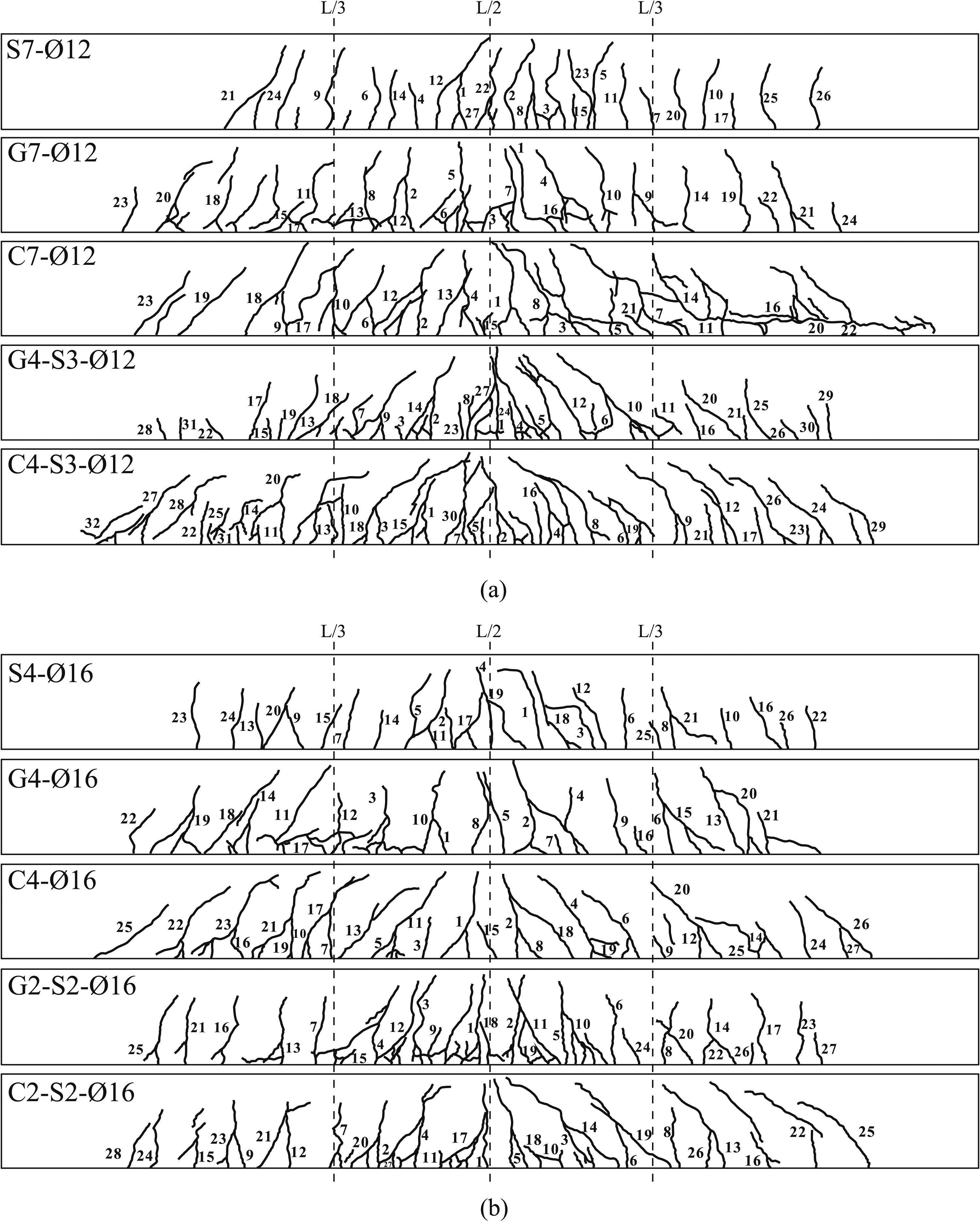
Load-displacement responses and stress-strain curves
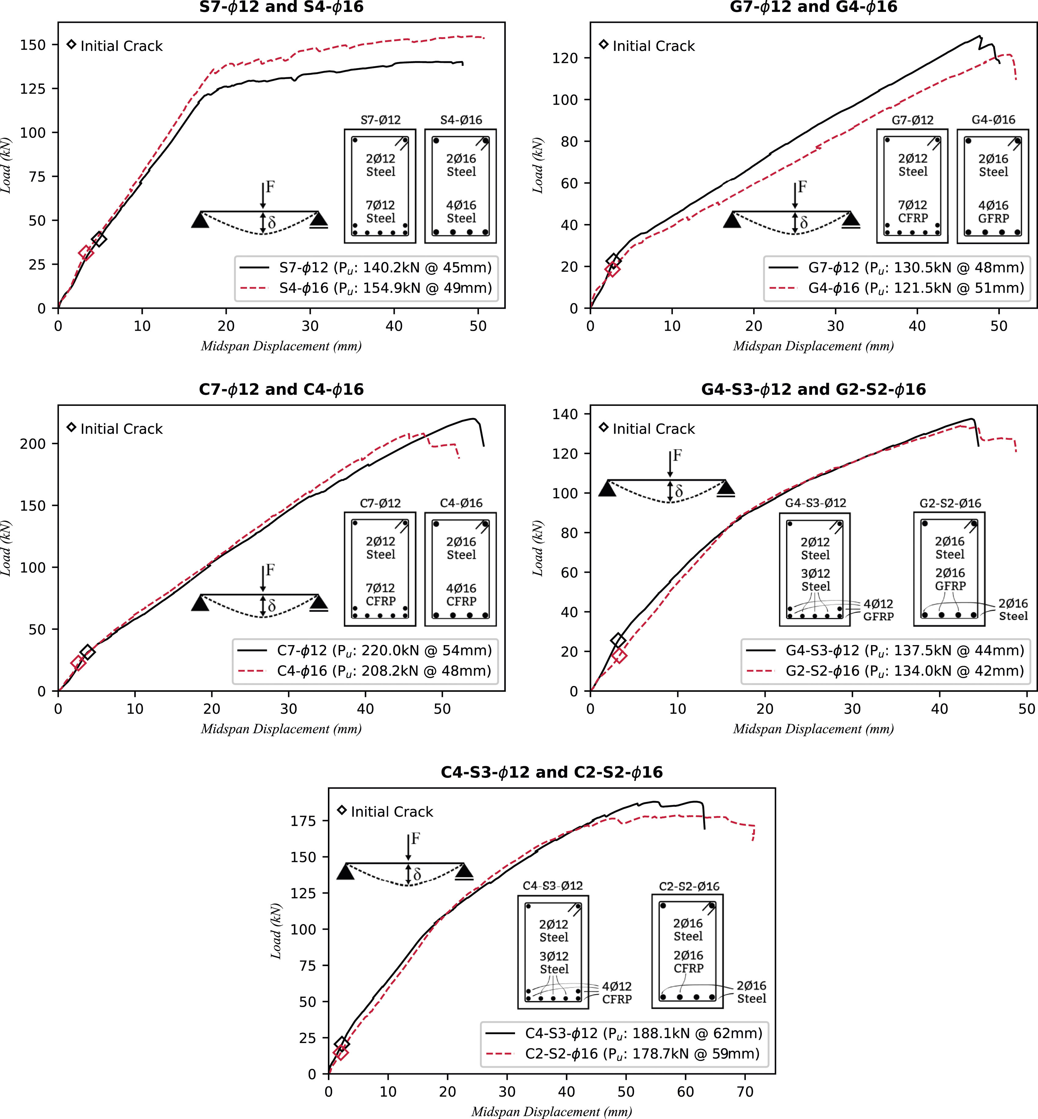
Figure 7 illustrates the load-displacement curves for Group I and Group II specimens, while Figure 8 provides a comparison of Group I specimens with their Group II counterparts. Until the initial cracking load, all specimens displayed similar load-displacement responses. GFRP-RC and CFRP-RC beams exhibited linear elastic behavior until failure, while hybrid GFRP-steel and CFRP-steel reinforced beams displayed some inelastic behavior due to steel yielding occurring before concrete crushing. Moreover, changes in rebar diameter affected the ultimate load and maximum displacements of the specimens, but the overall response remained similar for both Group I and Group II specimens. Load midspan displacement curves of Group I (left) and Group II (right). Comparison of Group I and Group II load-midspan displacement curves.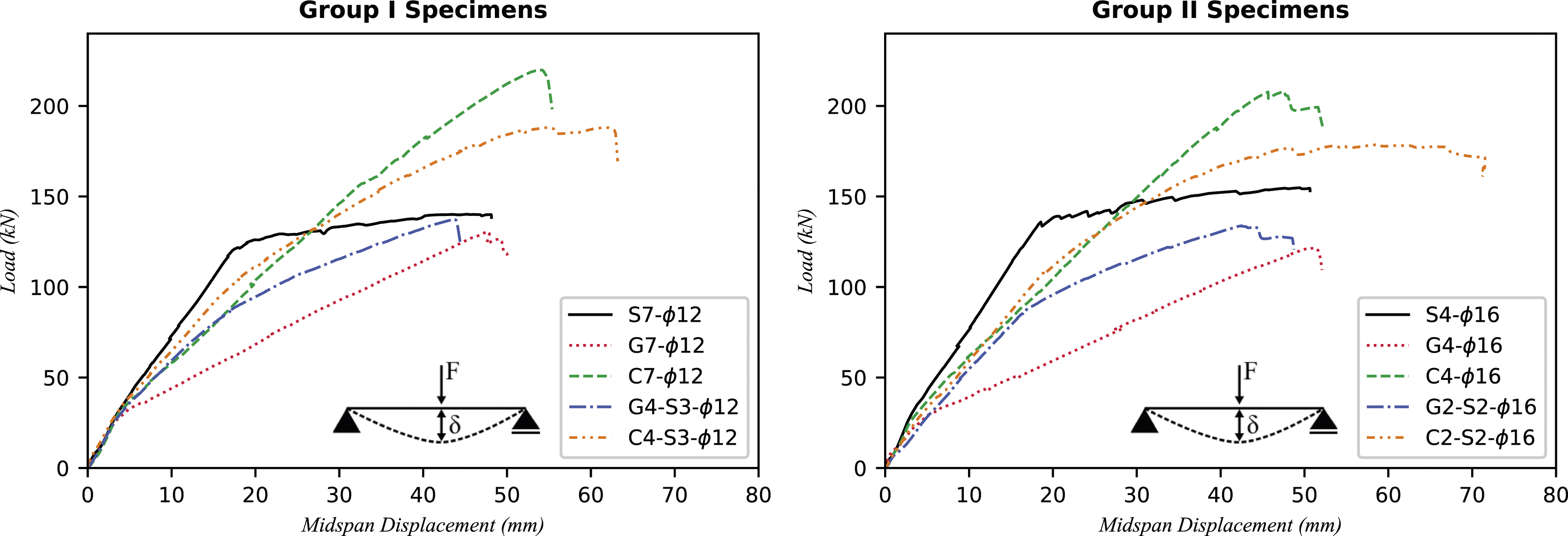
As given in Figure 1, each beam specimen instrumented with six strain gages placed on concrete, four on the midspan section (two 30 mm from top and two 30 mm from bottom) and two on the Load Concrete strain values at middle span and L/3.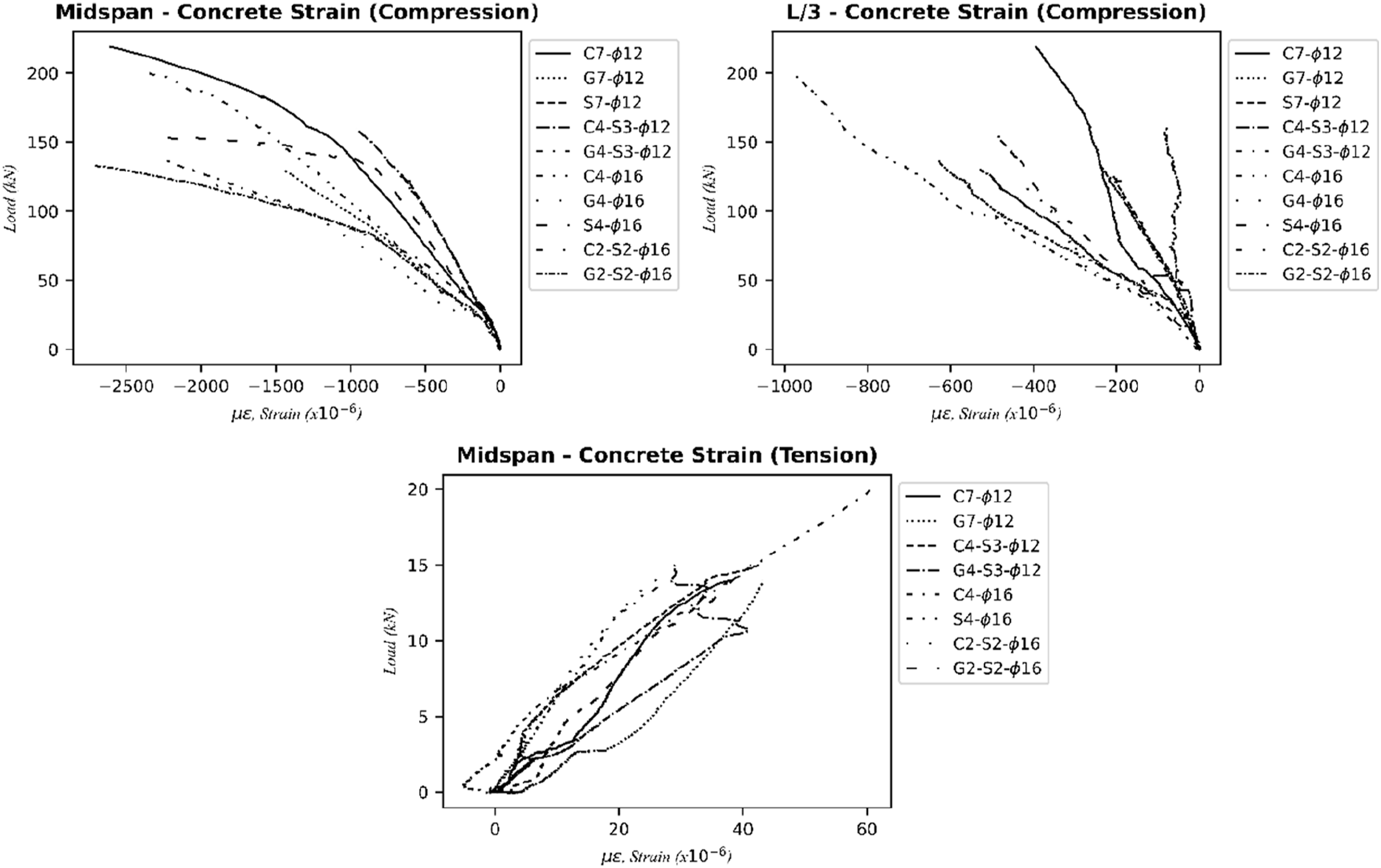
Discussion
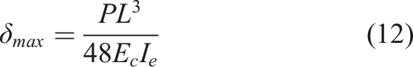
The deflection of an RC flexural member is one of the significant factors that affect its serviceability. Several researchers investigated the deflection behavior of FRP reinforced concrete beams (Bischoff, 2005; Bischoff and Gross, 2011; Dundar et al., 2015; Nguyen et al., 2020a; Kara et al., 2013; Kheyroddin and Maleki, 2017; Mohamed et al., 2017; Mousavi and Esfahani, 2012; Rafi and Nadjai, 2011; Unsal et al., 2017). The load-displacement behavior of RC beams under the static loading is the equation of the relation between the applied load and the flexural stiffness of the beam. There are two stages that define the deflection behavior of the RC beam. The first stage of the load-deflection curve is between the beginning of the loading to the initial crack occurrence, where the maximum service load moment is lower than the cracking moment (
ACI 440.1R-15 (2015) suggests using 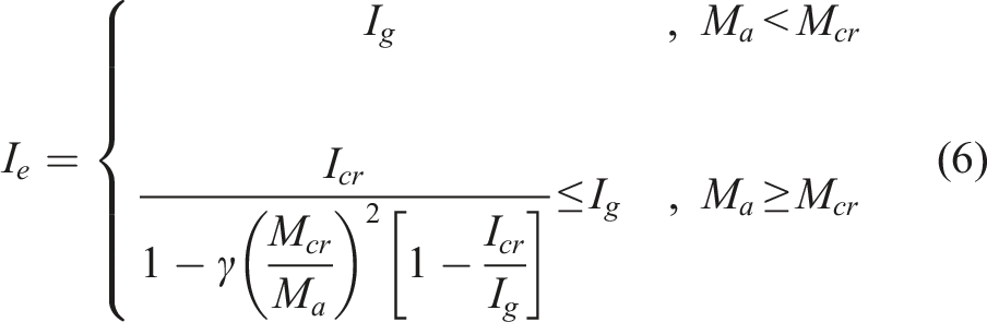
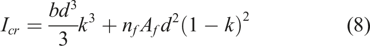

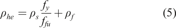
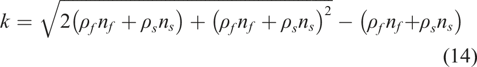
El Refai et al. (2015) defined the effective reinforcement ratio with equation (5) for hybrid reinforced (FRP-steel) beams. El Refai et al. (2015) proposed equation (13) for calculating the cracked moment of inertia of the hybrid reinforced RC beams including steel reinforcement components in equation (8) given by ACI 440.1R-15 (2015). The researchers redefined the 
ISIS Canada (2007) recommends using equation (16) for the effective moment of inertia of FRP reinforced beams. 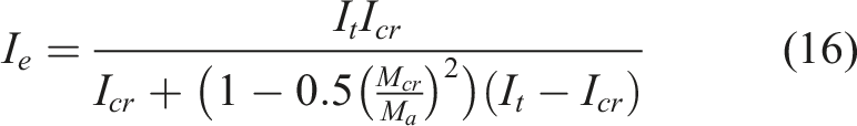
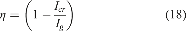
CSA S806-12 (2012) provides a maximum deflection equation derived by the curvature integration along the span of a simply supported beam subjected to one-point loading given by equation (17). The moment-curvature relation of FRP reinforced beam is assumed to be trilinear with the slope of three segments 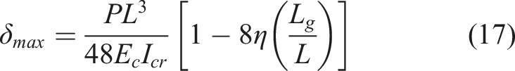
The cracking moment was predicted using equation (19), where the concrete modulus of rupture was calculated using equation (20) in accordance with ACI 440.1R-15 (2015) and equation (21) in accordance with CSA S806-12 (2012). The modification factor 


Dundar et al. (2015) proposed a numerical method for calculation of the displacements of FRP or steel-reinforced RC beams, and Unsal et al. (2017) presented an improved version for RC beams reinforced with a combination of FRP and steel rebars. The effective flexibility of beams at a specific section is calculated by equation (22) and used for determining the flexibility matrix of the member. The proposed method uses the complete moment-curvature relationship obtained from the sectional analysis, where the stress-strain relationships of the concrete and the reinforcement are considered. In this study, a computer program developed by Dundar and his colleagues (Dundar et al., 2015; Unsal et al., 2017) was used to estimate the deflections of the tested specimens. CEB-FIB model was used for concrete in compression.
The experimental and predicted deflection behavior of RC beams under applied load is compared in Figure 10. In order to compare the experimental results, the equations for deflection predictions suggested by the regulations and researchers for each reinforcement type were used. In Figure 10, the ultimate load level ( Comparison of load midspan curves with prediction methods.
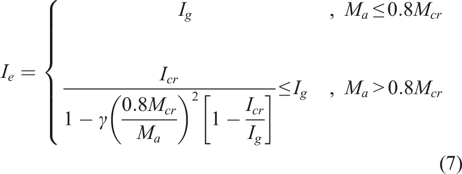
All predictions for the GFRP reinforced beams had very close results to the experimental behavior. Among these methods, ACI 440.1R.15 and ISIS Canada showed the closest load-displacement behavior for GFRP reinforced beams compared to other methods at service load levels. However, ACI 440.11.22 provided a conservative estimation of the behavior of GFRP reinforced beams compared to ACI 440.1R.15. Besides, all methods under-estimated the flexural behavior of the CFRP reinforced specimens. For hybrid GFRP-steel beams, while El Refai et al. (2015) and Unsal et al. (2017) obtained very similar results to the experimental behavior until the steel yielding point, the method proposed by El Refai et al. deviated from the experimental results after that point. As for hybrid CFRP-steel beams, a similar result was observed with hybrid GFRP-steel beams until the steel yielding point, while both methods deviated from the experimental results after that point.
Prediction of flexural behavior
Current codes and guidelines for FRP reinforced structures do not include CFRP reinforced beams as well as hybrid usage of FRP and steel reinforcements. This section introduces a new approach for estimating flexural behavior of CFRP-RC and hybrid reinforced (GFRP-steel and CFRP-steel) concrete beams. For CFRP-RC beams, the midspan deflections were calculated using the equations given by ACI 440.11-22 and CSA S806-12. For hybrid reinforced beams (GFRP-steel and CFRP-steel), midspan deflections were only calculated using ACI 440.11-22 with only changing the reinforcement ratio calculations using effective reinforcement ratio, 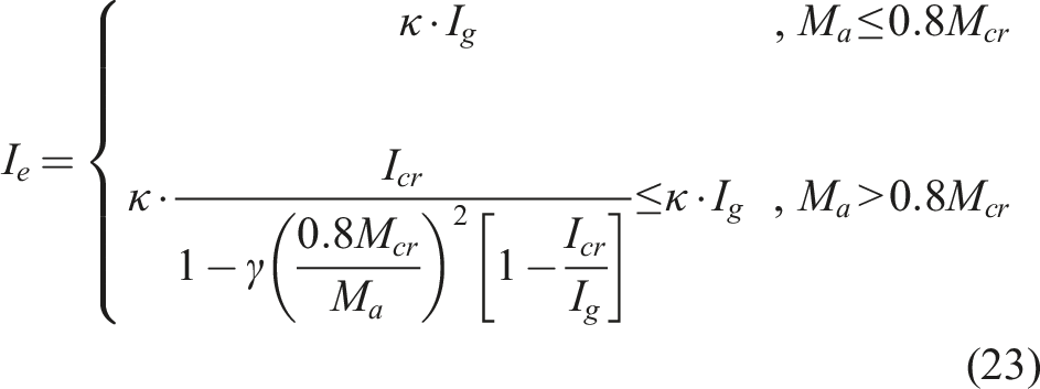
The predicted midspan deflections for RC beams reinforced with CFRP, GFRP-steel, and CFRP-steel are shown in Figure 11. The calculated κ factors for CFRP-RC, GFRP-steel, and CFRP-steel beams were 0.7, 0.68, and 0.6, respectively, and were found to agree well with experimental results. In particular, the predicted deflections for CFRP-RC beams closely matched the experimental behavior. On the other hand, it should be noted that the proposed method did not consider steel yielding. Thus, the non-linear Predicted midspan deflections for (a) CFRP reinforced, (b) GFRP-steel Reinforced and (c) CFRP-steel reinforced concrete beams.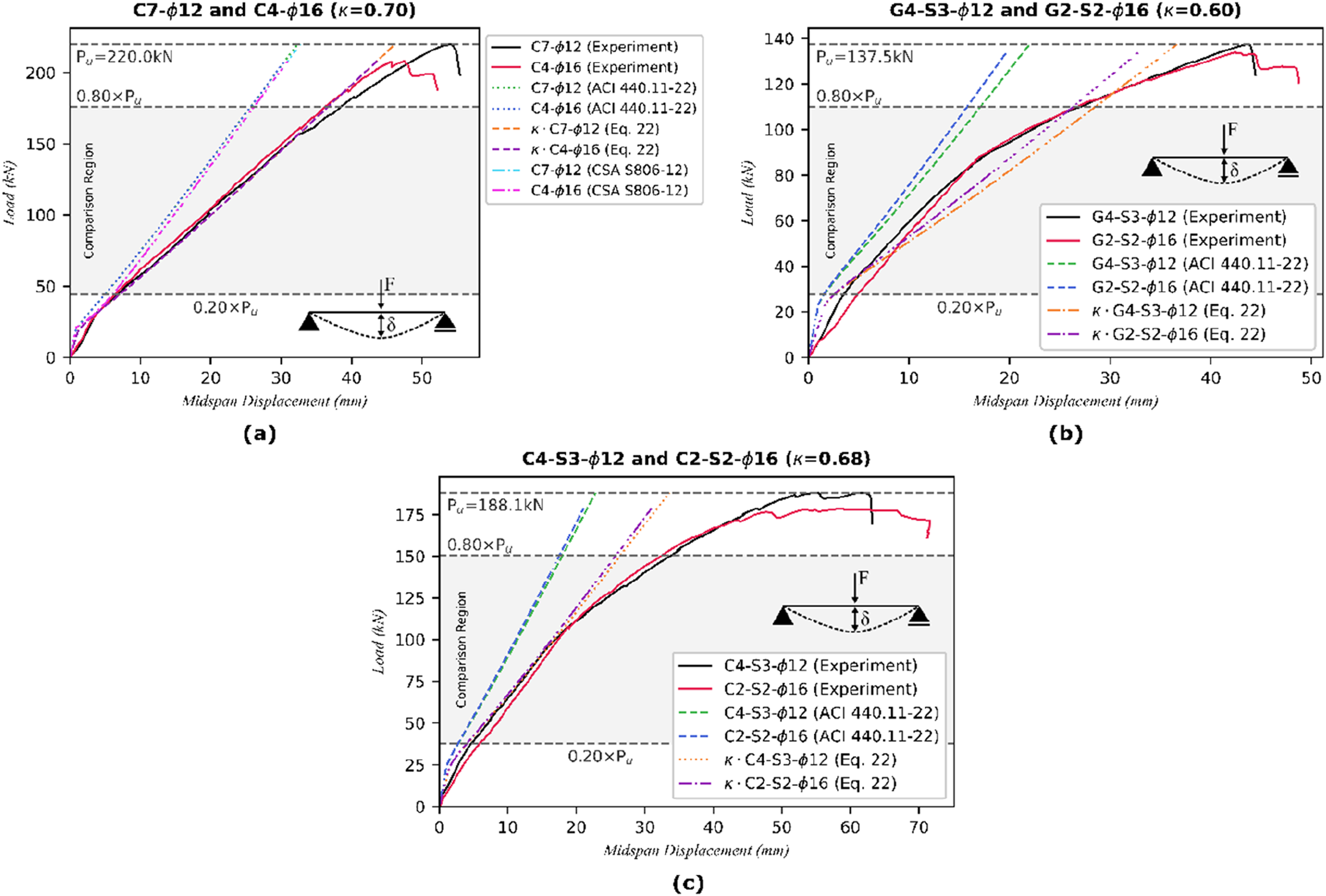
Experimental to predicted (δexp/δpred) midspan displacements of tested beams.
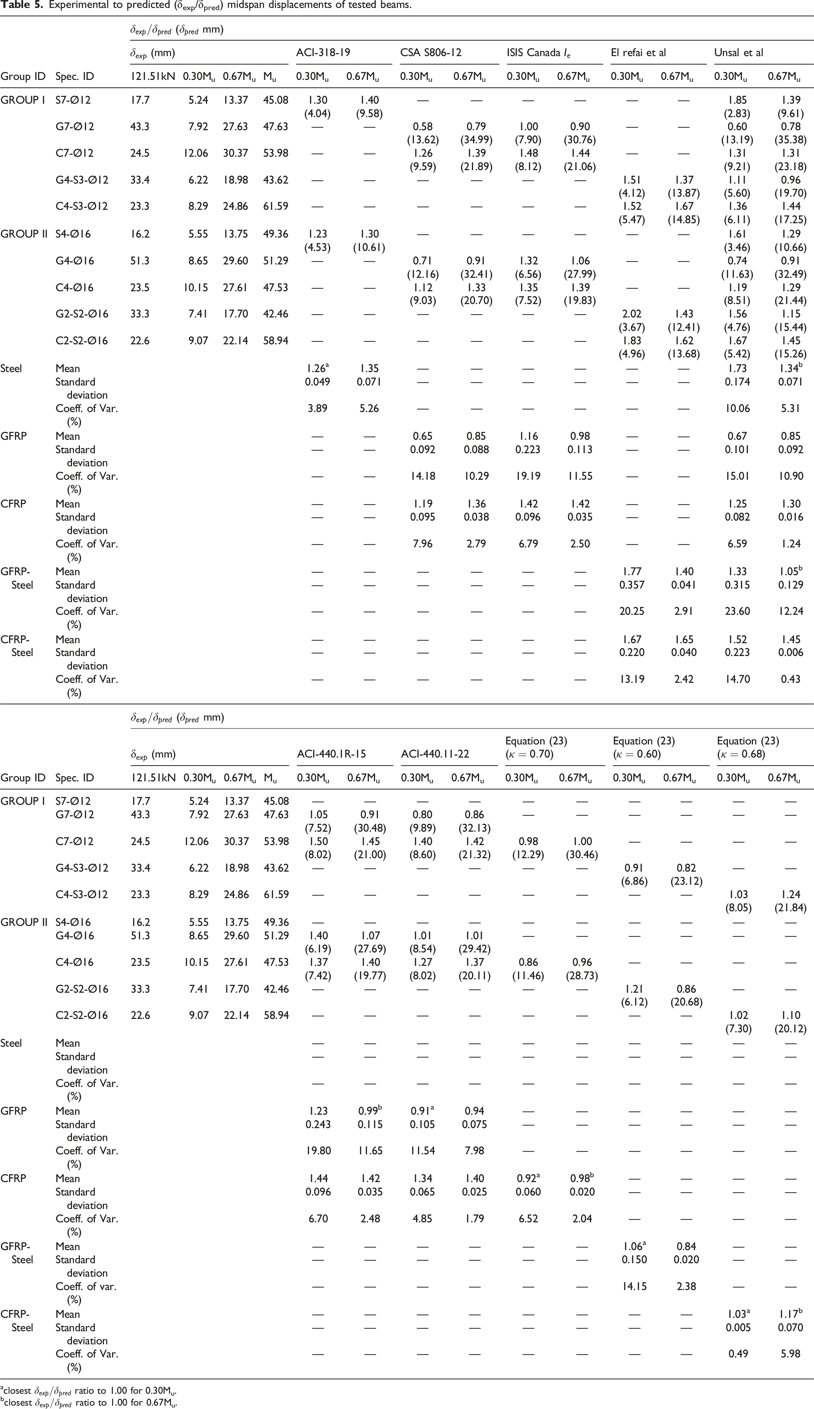
aclosest
bclosest
Conclusions
Based on the experimental results and prediction models, the following conclusions can be drawn: 1. The maximum load-carrying capacity of CFRP-RC beams were 1.82 and 1.57 times higher than GFRP-RC and Steel-RC beams, respectively. 2. Beams reinforced with GFRP rebars exhibited on average 5% higher midspan displacements and on average 15% lower ultimate load-carrying capacities compared to Steel-RC beams. 3. FRP reinforced beams failed by concrete crushing. The use of a hybrid combination of FRP and steel reinforcement changed the failure mode of FRP reinforced beams. Steel reinforcement yielded before the concrete crushing, similar to the behavior of conventional steel-reinforced beams. 4. The ultimate load-carrying capacity of hybrid GFRP-steel reinforced beams was on average 8% higher than that of GFRP-RC beams, while maximum displacements were on average 13% lower. Conversely, hybrid CFRP-steel beams had 14% lower ultimate load-carrying capacities than CFRP-RC beams, with an average of 19% higher midspan displacements. 5. Since all specimens casted by one batch of concrete, they have same concrete compressive strength; thus, the experimental study demonstrated that the type and diameter of reinforcement influenced the initial cracking load. The initial crack occurred at lower load levels with an increase in rebar diameter across all specimens. 6. The branching of cracks was more prevalent in hybrid specimens than in others, while the spacing between cracks along the span was shorter in hybrid specimens than in Steel-RC beams. 7. ACI 440.11-22 and CSA S806-12 provides better estimates for the displacements of GFRP-RC beams than CFRP-RC beams. However, all methods included in this study (except the proposed method by the authors) overestimated midspan displacements of GFRP-RC beams and underestimated the midspan displacements of CFRP-RC beams. For hybrid reinforced beams, El Refai et al. (2015) and Unsal et al. (2017) methods underestimate the midspan deflections for GFRP-steel and CFRP-steel beams. 8. Equation (23), proposed in this study, showed a good correlation for predicting the flexural behavior of CFRP-RC, hybrid GFRP-steel, and CFRP-steel beams. The reduction factor, κ, proposed for CFRP-RC, GFRP-steel, and CFRP-steel beams are 0.7, 0.68, and 0.6, respectively. Predicted midspan displacements for CFRP-RC well estimates the experimental results with almost no difference. For the hybrid reinforced beams, even though the load-deflection behavior after steel yielding becomes parabolic instead of linear, the predicted results using equation (23) still demonstrate better correlation with experimental results than those from the ACI 440.11-22 formulas.
Footnotes
Acknowledgments
The authors are greateful for the Scientific Research Projects Fund provided by Eskisehir Osmangazi University (Project Number: 201715D32). The authors also would like to express their special thanks and gratitude to Dr Mehmet Canbaz for his generous help with the material tests.
Declaration of conflicting interests
The author(s) declared no potential conflicts of interest with respect to the research, authorship, and/or publication of this article.
Funding
The author(s) disclosed receipt of the following financial support for the research, authorship, and/or publication of this article: This work was supported by the Eskisehir Osmangazi Universitesi; Project Number: 201715D32.
Data Availability Statement
Data will be made available on request.