
Abstract
This study investigates the response of small-scale, reinforced ultra high performance concrete beams. Seven specimens were cast and experimentally tested. Steel fiber volume fraction, amount of longitudinal and transverse steel reinforcement, and casting direction varied between specimens. High longitudinal reinforcement ratios of 4.1% and 9.5% were expected to drive relatively large shear demands and low steel fiber volume fractions of 0.5% and 1% were expected to decrease the UHPC’s ability to resist tension, shear, and compression. Specimens were either cast at one end or mid-span. All specimens failed in shear, as expected. R/UHPC beams with only 0.5% fibers and a stirrup spacing equal to half the beam’s depth carried more ultimate load than beams with 1% fibers and twice the stirrup spacing. At a 0.5% fiber volume fraction, UHPC performed well, exhibiting fiber bridging in tension and resisting spalling in compression. As longitudinal reinforcement ratio increased from 4.1% to 9.5%, load carrying capacity generally increased, but not proportional to the increase in steel. Placement method did not influence fiber orientation in the R/UHPC beams when measured in 2D planes transverse or longitudinal to the specimens’ major axis. The longitudinal and transverse reinforcement interrupted fiber flow and prevented significant fiber alignment; combined with the short span of the beams, these factors mitigated the influence of placement method.
Keywords
Introduction
Ultra high performance concrete (UHPC) is a high compressive strength (150 MPa (22 ksi)) (Pourbaba et al., 2019), fiber reinforced class of cementitious material. UHPC typically includes steel fibers, between 1–3% by volume, which provide tensile strength, pseudo-strain hardening, crack control (Bermudez et al., 2022), compressive toughness (Kodur et al., 2018), and enhance confinement and bond when reinforced with steel bars (Hung and Chueh, 2016). These material properties and behavior make UHPC an excellent choice for multiple structural applications to include bridge components, pre-stressed girders, and highway overlays.
Assessment of the literature regarding failure modes in R/UHPC beams
Fifteen studies of rectangular R/UHPC beams were identified in the literature, containing a total of 112 individual specimens. Longitudinal reinforcement ratio, stirrup spacing-to-depth ratio, shear span-to-depth ratio, and steel fiber volume fraction for each specimen were collected (Appendix A). Additionally, the ultimate drift and failure mode were collected whenever reported or inferred from the literature. Ultimate drift was calculated as mid-span deflection divided by shear span and reported as a percent. Specimen size, grade of longitudinal reinforcement, length or type of steel fibers, flexural and compression strength of the cementitious matrix, stirrup size, type and grade, and placement method were not compiled.
Of the 112 specimens in the literature, failure modes were reported or can be inferred from 107 of the specimen tests and grouped into four general categories. Crushing was reported in nine specimens, wherein load carrying capacity of the R/UHPC beam dropped due to insufficient ability to carry compressive loads. No spalling was reported, due to the fibers physically holding together the compression block. Flexural failure was reported in 40 specimens, wherein excessive bending stress resulted in either fiber bridging failure at a dominant crack (e.g., as described by Yang et al., 2010), gradual strain hardening of the longitudinal rebar (e.g., as described by Shao and Billington, 2022), or rebar fracture. Flexural shear failure was reported in five specimens, wherein load carrying capacity decreased with the widening of a dominant flexural shear crack. Lastly, shear failure was reported in 53 specimens, which was the result of diagonal cracking that reduced the load carrying capacity of the specimens.
Assessment of the literature regarding shear failure in R/UHPC beams
Thirty six of 37 specimens with a shear span-to-depth ration (a:d) of 2.0 or less failed via shear failure. Fifteen of 23 specimens with a:d over 2.0 and equal to 3.0 or less also failed in shear. These results are not surprising given the increase in shear demand when shear span is relatively shorter compared to when shear span is longer. Shear failures were observed across a wide range of fiber volume fractions, from 0.11% to 2.65%, indicating that fiber volume fraction alone is not a strong indicator of failure mode.
Shear failure was far more common as longitudinal reinforcement increased across the range in the literature from 0.53% to 7.8%. Among the 57 specimens with a reinforcement ratio of 3.0% or less that reported failure mode, only nine failed in shear. In contrast, 50 of 59 specimens with a reinforcement ratio over 3.0% reported a shear failure mode. Larger longitudinal reinforcement ratios increased the flexural capacity of the specimens and thus made shear failure more likely.
Across the 112 specimens in the literature, the stirrup spacing-to-depth ratio, s:d, ranged from 0.316 to 5.94. Many previous studies experimented with R/UHPC beams without stirrups, in which case s:d was documented as equal to a:d. Shear failure was rare among specimens with s:d less than 1.0; only six of 35 specimens in this range failed by shear failure. With a smaller s:d, the transverse steel often provided sufficient shear capacity such that the specimens failed in modes other than shear failure. Specimens with s:d between 1.0 to 2.5, meaning diagonal cracks could form between stirrups, failed in shear in all 34 of 34 specimens. In specimens with s:d greater than 2.5, 17 of 42 specimens failed via shear failure. Specimens with s:d greater than 2.5 were also generally flexurally dominant and the shear demand, and thus, propensity to fail in shear, was low.
Specimens that failed in shear experienced less ductility, or a lower ultimate drift, on average, than the mean ultimate drift among the 112 specimens in the literature. The mean ultimate drift of all specimens in the literature is 5.31%. However, the average reported ultimate drift of the specimens that failed in shear was only 4.48%.
Assessment of the literature regarding knowledge gaps in R/UHPC beam response
Figure 1 shows the data collected from the 15 previous studies listed in Appendix A. The 25 sub-plots show values of s:d, Vf, ρ, a:d, and ultimate drift relative to each other. Data points are color-coded by failure mode. Regions within any sub-plot where there are sparse or no data points indicate a lack of previous investigation and potential areas of future study to close knowledge gaps. Very high longitudinal reinforcement ratios, from about 3% to 8%, have not yet been studied in R/UHPC specimens with large a:d, between about 3 to 6. Specimens in this a:d range would be flexurally dominant and, with reinforcement ratios above 3%, might be able to more fully utilize the tension steel to efficiently take advantage of the superior compression properties of UHPC and its resistance to crushing and spalling, as suggested by Shao and Billington (2022). Data from the 15 previous studies shown in Appendix A comparing specimen drift, stirrup spacing-to-depth ratio (s:d), fiber volume fraction (Vf), reinforcement ratio (ρ), and shear span-to-depth ratio (a:d).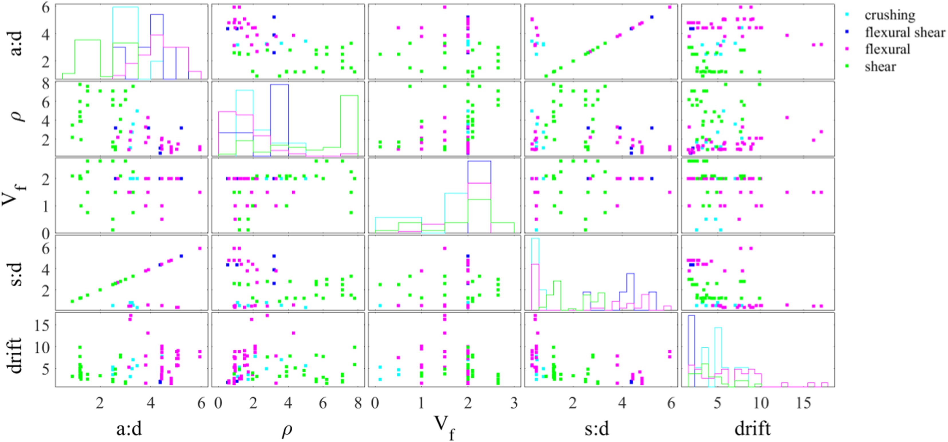
There is a lack of studies considering R/UHPC specimens with a low fiber volume fraction, below 2%, and particularly below 1%. This low fiber volume fraction is atypical in proprietary UHPC mixes, but as the steel fibers are often the most expensive constituent in UHPC, exploring structural response when fiber volume fraction is low could be particularly economical. Specimens with low fiber volume fractions in conjunction with longitudinal reinforcement ratios above 2% are particularly lacking in the literature.
R/UHPC specimens with high reinforcement ratios combined with large stirrup spacing is another current gap in the literature. These specimens would have a high flexural capacity and a low shear capacity, and the transition between flexural and shear failure modes could be better understood by studying them.
A low fiber volume fraction combined with a close stirrup spacing could limit shear capacity in R/UHPC specimens due to the lower fiber content allowing for a dominant crack to form at a lower load. This is an area of study with few specimens reported in the literature. Fiber volume fractions less than 2% and s:d greater than 1.0 would challenge the UHPC matrix’s ability to resist the shear demand. Recording the failure modes of these specimens as either flexural or shear-related would be insightful for the body of knowledge.
Purpose
This study leverages the lessons learned from previous work and acknowledges the gaps in existing knowledge. Relatively low fiber volume fractions (0.5% and 1%) and relatively high longitudinal reinforcement ratios (4.1% and 9.5%) were chosen for the R/UHPC specimens in this study. This type of experimental specimen design that favors tension steel over steel fibers is intended to follow the recommendations of Shao and Billington (2022) for a more cost effective and efficient use of steel within R/UHPC beams. Further, R/UHPC beams with higher reinforcement ratios can develop greater flexural strength for a given cross section, thus reducing the total volume of materials needed. Relatively low a:d (near 2%) and s:d (1.0 or less) make for shear-dominant specimens, requiring transverse steel to provide shear capacity above that of steel fibers alone. This study centers aims to help answer the following research questions: 1. How do short span R/UHPC beams with a stirrup spacing of “d” and 1% steel fibers by volume perform compared to beams with a stirrup spacing of “d/2” and only 0.5% fibers? 2. How does short span R/UHPC beam performance change when reinforcement ratio is increased? 3. How does fiber orientation differ when R/UHPC beams are cast from the center of the mold compared to when cast from the end?
Review of the literature pertaining to research questions
Previous research has shown that the design variables most pertinent to shear in R/UHPC beams are shear span (a:d), steel fiber volume fraction, longitudinal steel, and transverse steel (Jin et al., 2015). This informed the selection of stirrup spacing and fiber volume fraction in research question one. Furthermore, other studies have shown that design variables are intertwined; tailoring both the fiber content and reinforcement ratio is required to ensure strain-hardening behavior and specimen ductility in R/UHPC beams (Yavas and Goker, 2020) and (Gomaa et al., 2021). Past studies have shown the importance of transverse steel in shear response of R/UHPC beam. When the shear span-to-depth ratio (a:d) was nearly 2, shear ductility improved by 200% as the transverse steel ratio increased from 0.25% to 0.45% (Wang, et al., 2020). Additionally, when a set of R/UHPC beams was tested, crack widths were smaller in the specimens containing transverse steel when compared to ones without transverse steel (Baby, et al., 2010).
To determine longitudinal reinforcement ratios in research question two, several studies have made recommendations on efficient design in UHPC beams. Substituting fibers for longitudinal steel is advantageous due to the higher cost of fibers relative to deformed steel bars. With fiber volume factions as low as 0.5% in R/UHPC beams, crack width control and crushing resistance were found to be sufficient (Shao and Billington, 2022). Furthermore, a high longitudinal reinforcement ratio was recognized as facilitating more full utilization of UHPC’s compression properties. Thus, a relatively low fiber volume fraction and a relatively high longitudinal steel reinforcement ratio above that recommended for reinforced concrete were determined to be most effective in terms of cost, ductility, and producing warning before failure (Shao and Billington, 2022).
UHPC placement, e.g., whether a specimen is cast at the end or at mid-span, can affect fiber orientation. Studies have shown that when UHPC specimens were cast at one end, fibers were more aligned with each other than when cast at mid-span (Islam and Zhang, 2023). Furthermore, research has shown that fiber orientation differs with UHPC placement. Specimens cast at mid-span resulted in an increase in fibers near mid-span, which aided in crack bridging, and resulted in higher flexural capacity than specimens cast at one end (Yoo et al., 2014). In tensile specimens, UHPC placement methods have been shown to affect fiber orientation, which directly impacted tensile properties such as first cracking stress, average multi-cracking strength, and strain at localization (Graybeal et al., 2016). Studies show the size and geometry of specimens influence fiber orientation. Fibers in smaller specimens tended to arrange in a more favorable orientation to resist tension than in larger specimens (Yoo et al., 2016). Finally, formwork has been shown to cause fibers to orient themselves parallel to the formwork surfaces during casting when the distance to the formwork is less than or equal to the length of the fibers (Islam and Zhang, 2023). The above references informed using two placement methods for this study involving R/UHPC beams to investigate research question three: at the end and at mid-span.
Methods
UHPC mix proportions.
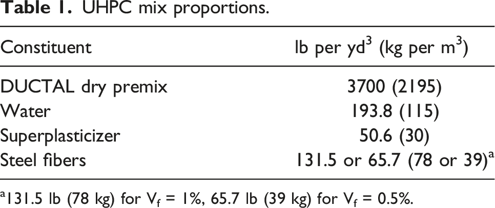
a131.5 lb (78 kg) for Vf = 1%, 65.7 lb (39 kg) for Vf = 0.5%.
A horizontal pan mixer was used, and specimens were cast by placing the UHPC in two methods: casting at one end of the form or casting at the middle of the form shown in Figure 2. Flow was measured at 85% per ASTM C 1437 (Standard Test Method for Flow of Hydraulic Cement Mortar, 2020). Placement methods.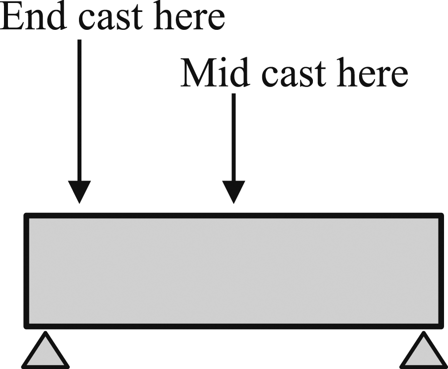
All specimens were cured for approximately 28 days in a 72°F (22°C) water bath. Two days before testing, the beams were removed from the warm water bath and painted white and speckled with black dots. The speckles were placed randomly by using black marker over white paint, and varied size for digital image correlation (DIC). The speckles varied significantly in size and spacing; the range of sizes for the speckles was 0.0450 inches to 0.375 inches (1.14 mm to 9.53 mm) and spacing between them was 0.0250 inches to 0.500 inches (0.635 mm to 12.7 mm).
Compressive strength and modulus of rupture (MOR) were determined for the UHPC mix with 0.5% fibers by volume. The average compressive strength, using 3-inch (75 mm) diameter cylinders per ASTM C1856 (Standard Practice for Fabricating and Testing Specimens of Ultra-High Performance Concrete, 2017), was 18.5 ksi (128 MPa). Third point bending tests were conducted using 4 in. × 4 in. (101 mm × 101 mm) rectangular prisms; MOR was 1.92 ksi (13.2 MPa).
The longitudinal reinforcement was Grade 60 No. 6 (20M) bars, and the transverse reinforcement was Grade 100 No. 3 (10M) bars. Yield and ultimate strength for longitudinal reinforcement were 78.0 ksi (538 MPa) and 111 ksi (765 MPa), respectively. The yield and ultimate strength of the transverse reinforcement were 127 ksi (876 MPa) and 169 ksi (1170 MPa), respectively. All beam cross sections were 4 in. × 7 in. (10.2 cm × 17.8 cm), and length was 26.5 inches (67.3 cm) (Figure 3). R/UHPC specimen design showing side view with (a) stirrup spacing of “d,” (b) stirrup spacing of “d/2” and cross-section with (c) ρ = 9.5% and (d) ρ = 4.1% (1 in. = 2.54 cm).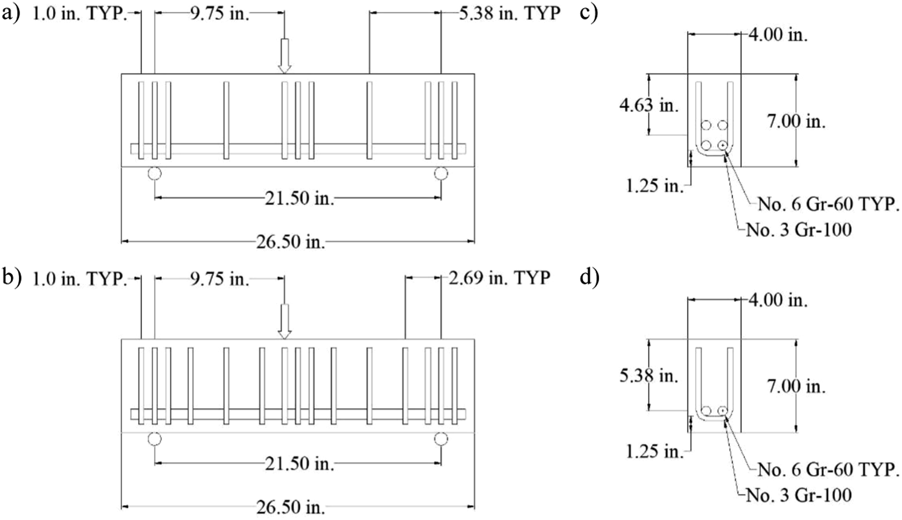
Testing matrix.
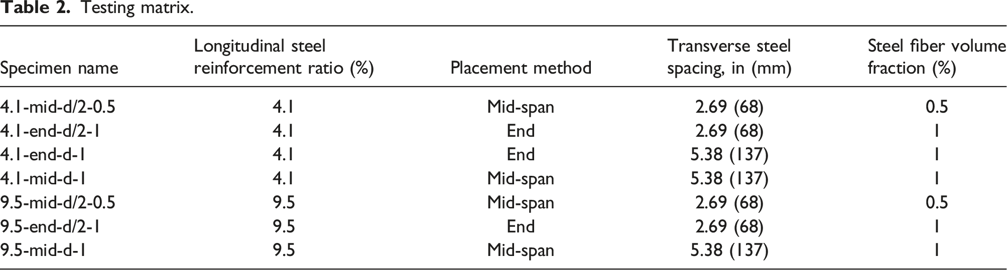
Each specimen was monotonically tested under three-point bending at 28 ± 2 days. The loading was off-centered to cause failure on one span of the specimen as done in other work, e.g. (Gomaa and Alnaggar, 2019). Testing was deflection-controlled at a rate of 0.1 in/min (2.54 mm/min), and all beams were tested until failure, defined herein as when strength dropped to less than 50% of the peak strength recorded. Crack patterns, type, and width were monitored continuously. Additionally, high-resolution photographs were taken throughout testing for subsequent DIC. After completion of testing, beam specimens were cut transverse to their longitudinal axis at their quarter-points and along the longitudinal axis. A handheld pavement saw was used to make all cuts. The sections were then polished and wet with water, which facilitated high-resolution photography of the beams’ cross-sections. Specimens were then cut and polished parallel to their longitudinal axis for additional high-resolution photography. The photographs were used to analyze fiber orientation as described in the Image analysis of transverse cuts and Image analysis of longitudinal cuts sections.
Results and discussion
Specimen response
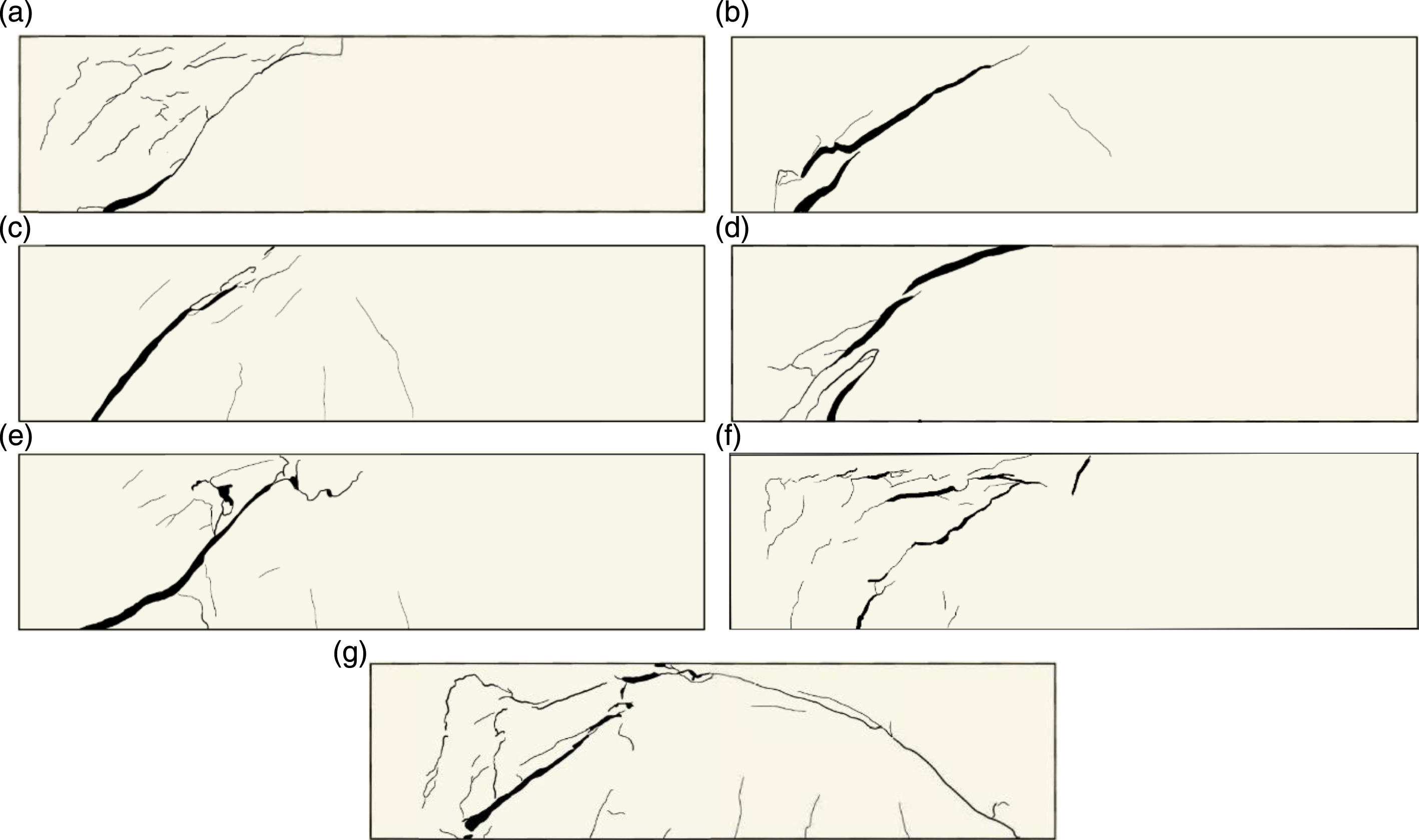
All specimens failed in shear, as expected. Load versus drift results for the seven specimens are shown in Figure 4. Specimen 4.1-mid-d/2-0.5 was expected to achieve yield strength of the longitudinal steel prior to failure due to the presence of closely spaced stirrups. During the test, shear cracks began to form near 1.9% drift, but were bridged by the fibers. One shear crack became dominant when it exceeded 0.012 inches (0.3 mm) at 2.1% drift. Strain accumulated at the dominant shear crack through approximately 2.8% drift, however the crack width remained small at the location of the stirrup. Then multiple shear cracks formed and grew while the load carrying capacity diminished almost linearly from a peak value of 53.1 k (236 kN) through failure. Final cracking patterns of each specimen are shown in Figure 5. The test was concluded due to strength loss from a shear fiber bridging failure at an ultimate drift of 4.7%. Based on the peak load, it appears the longitudinal steel yielded; however, the top of the specimen did not experience a crushing failure. Due to its shear failure prior to the longitudinal steel’s strain hardening, the specimen was not able to fully utilize the tension capacity of the longitudinal steel to provide additional strength or ductility. Load versus drift. Final cracking pattern of specimens. (a) 4.1-mid-d/2-0.5. (b) 4.1-end-d/2-1. (c) 4.1-end-d-1. (d) 4.1-mid-d-1. (e) 9.5-end-d/2-1. (f) 9.5-mid-d/2-0.5. (g) 9.5-mid-d-1.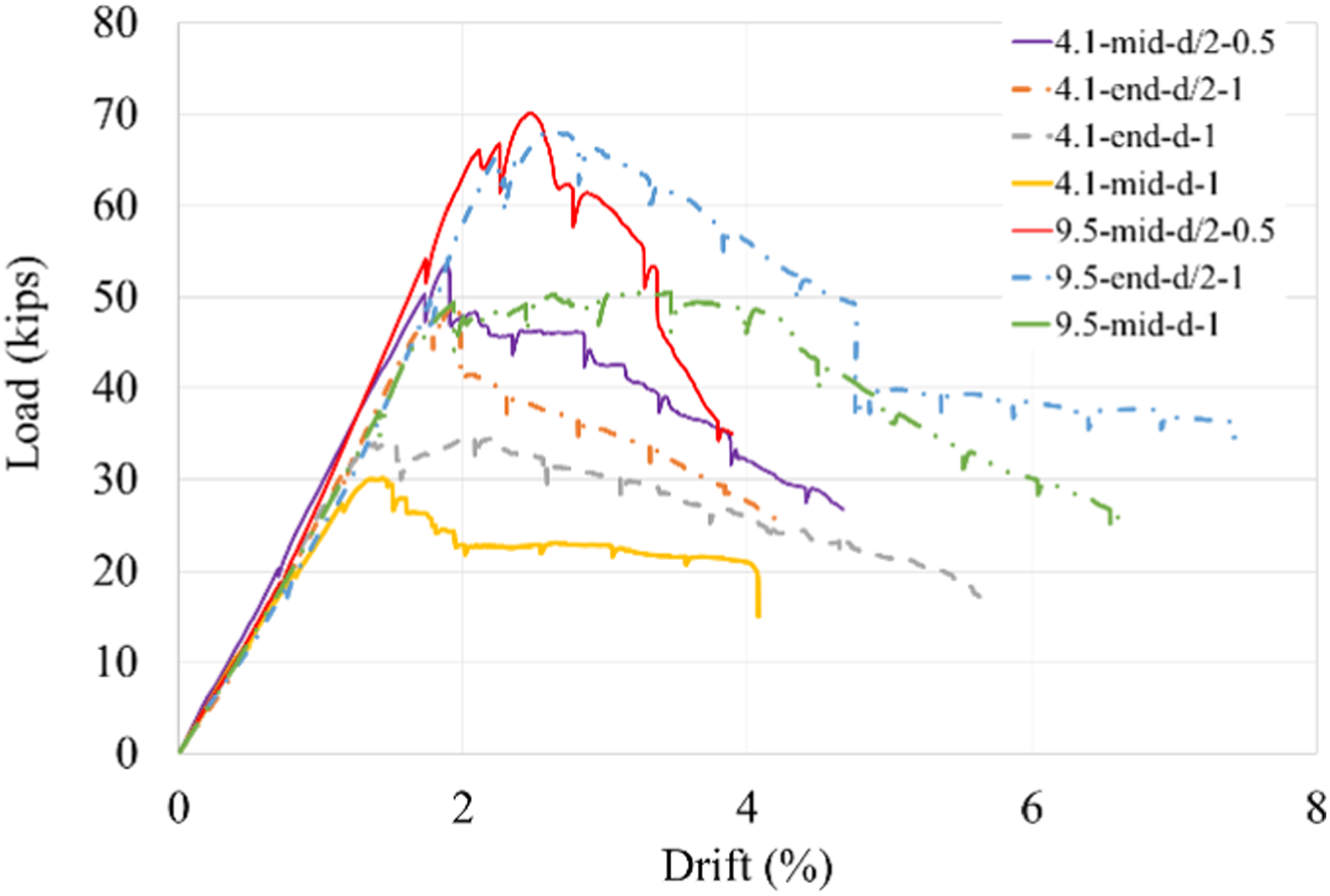
Specimen 4.1-end-d/2-1 was expected to have a high shear capacity due to the close spacing of the transverse reinforcement. During the test, shear cracks formed near 1.8% drift and remained less than 0.3 mm wide due to the bridging capability of the steel fibers. The dominant shear crack was apparent at 2.1% drift but the crack width was notably smaller at the location of the stirrup as the transverse steel bridged the dominant shear crack. After reaching its peak strength of 49.5 k (220 kN), multiple shear cracks began to form as the load carrying capacity diminished. No crushing in the UHPC was observed. The gradual decrease in post-peak load carrying capacity was due to fiber bridging failure, and ultimate drift was 4.6%.
With fewer stirrups, specimen 4.1-end-d-1 was expected to also fail by shear, but prior to yield. The first shear crack appeared at 1.3% drift. By 1.5% drift, the shear crack was noticeably wider as the fibers began to lose their bridging capacity. The peak strength was 34.6 k (154 kN), 53.7% less than specimen 4.1-end-d/2-1 as the increased stirrup spacing provided less capacity to support the shear demand. At 2.0% drift, dowel action was vital to providing ductility, and prolonging failure until ultimate drift of 4.1%.
Specimen 4.1-mid-d-1 was expected to perform similarly to specimen 4.1-end-d-1. During testing, the first shear crack formed at 1.3% drift. By 1.5% drift, fibers began to lose capacity across a dominant shear crack. Authors observed a peak load of 29.5 k (131 kN) and 1.5% drift, which was similar to the drift of the 4.1-end-d-1. Multiple shear cracks did not form due to the absence of a stirrup to bridge the crack. After 2.0% drift, significant dowel action kept the specimen’s load carrying capacity above 50% of peak until an ultimate drift of 4.1% when the specimen failed.
Specimens with a steel reinforcing ratio of 9.5%, combined with the shear span-to-depth ratio near 2 were expected to drive a high shear demand on the R/UHPC beams. First cracking in specimen 9.5-mid-d/2-0.5 was a shear crack at 2.1% drift. As deflection increased, flexural shear, shear cracks, and crushing were noticed. Flexural shear cracks remained bridged, under 0.0079 inches (0.2 mm), throughout the duration of the test, and no spalling due to crushing occurred. A period of pseudo strain-hardening was most apparent in this specimen, as illustrated by the gain in specimen strength from 64.4 k (286 kN) to 69.6 k (310 kN) between 2.1% and 2.5% drift. One dominant shear crack formed at 3.4% drift after which strength decreased rapidly to failure. The dominate shear crack width remained small at the location of the stirrup. Based on the peak load of 70.2 k (312 kN), the longitudinal steel did not yield, therefore using 9.5% reinforcement ratio was excessive for this beam’s design. The presence of crushing without abrupt crushing failure indicated the enhanced compression properties of UHPC were utilized. Crushing appeared without significant multiple cracking, thus the ultimate drift achieved by specimen 9.5-mid-d/2-0.5, as measured by ultimate drift, was 3.9%.
As specimen 9.5-end-d/2-1 began testing, an initial shear cracking was noticed at 2.1% drift. As loading and deflection increased, more shear cracks along with flexural shear cracks and crushing were observed. Throughout the experiment, the flexural shear cracks remained under 0.0079 in. (0.2 mm) wide, as they were bridged by the steel fibers. This specimen reached a peak load of 68.3 k (304 kN) and no spalling occurred. UHPC’s compression fracture toughness kept the compression block intact and facilitated ultimate drift of 7.4%.
The first shear crack formed on both spans at 1.2% drift in specimen 9.5-mid-d-1. As loading increased, some small flexural and flexural shear cracks formed, and one shear crack became dominant. The longitudinal bars in specimen 9.5-mid-d-1 did not yield and achieved a peak load of 50.7 k (226 kN), or only 72.3% of specimen 9.5-mid-d/2-0.5. Comparing the peak strength of the two specimens with 9.5% reinforcement ratio indicates that cutting by half the stirrup spacing was a more effective means of providing shear strength and facilitating load-carrying capacity than doubling the steel fiber content from 0.5% to 1% by volume. The peak strength of specimen 4.1-mid-d/2-0.5 was 5.6% greater than that of 9.5-mid-d-1, demonstrating inefficient use of longitudinal steel in specimens with large stirrup spacing. After the peak load, strength remained fairly constant until approximately 4.0% drift then decreased linearly until specimen 9.5-mid-d-1 failed at an ultimate drift of 6.7%.
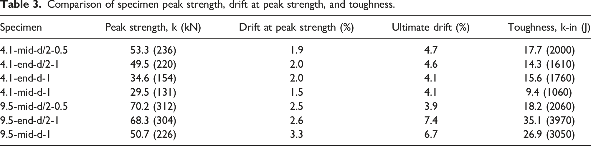
Comparison of specimen peak strength, drift at peak strength, and toughness.
Digital image correlation
Two-dimensional DIC was used to calculate shear, compressive, and tensile strain in specimens. Analysis of the photographs was conducted using Ncorr (Blaber et al., 2015) running through commercial software Matlab 2022b (The Mathworks Inc, 2022). DIC was completed in four steps to report captured strain values. First, a reference image of the specimen setup before loading was used to set initial positions and select the region of interest. Then, appropriate seeds, subset size and spacing were selected for tracking of the black speckles while the beam underwent loading. After completion of the analysis, strain was shown in a color-coded heat map and a scale was applied using the known distance between the beams’ supports. With the image resolution and methods utilized for DIC, accuracy is expected to be +/− 3.5%.
The purpose of using DIC was to analyze the micromechanical performance of fiber bridging in a specimen with a 0.5% steel fiber volume fraction during the initial stages of cracking. Even with the lower of the two fiber volume fractions investigated, the specimen demonstrated the ability to bridge cracks in shear, compression, and tension. All specimens tested experienced a shear failure, and DIC captured values of localized strain during fiber bridging of specimen 4.1-mid-d/2-0.5. This specimen bridged the dominate shear crack at a shear strain of 0.0020. (Figure 6(a)). Additionally, DIC captured a compression strain of 0.0054 (Figure 6(b)) at peak load in the same specimen. Despite this compressive strain, the specimen did not spall, and continued to carry compressive forces. DIC also identified the tension strain experienced while still bridging flexural cracks. Specimen 4.1-mid-d/2-0.5 achieved a tension strain of 0.0023 during fiber bridging (Figure 6(c)). These results provide information for R/UHPC beams with fiber volume fractions below 1% and reinforcement ratios above 2%, where a dearth of data currently exists (see Figure 1). Additionally, the captured strain values support previous findings that a fiber volume fraction of 0.5% is sufficient to resist crushing (Shao and Billington, 2022). Specimen 4.1-mid-d/2-0.5 DIC strain results for (a) shear during fiber bridging, (b) compression at peak load, and (c) tension during fiber bridging.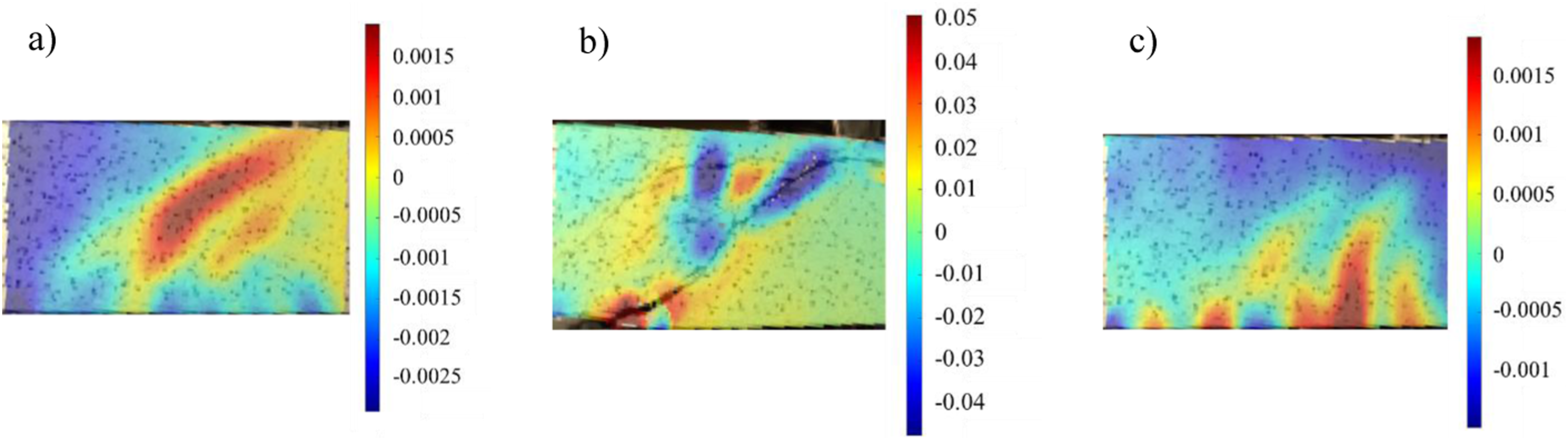
Image analysis of transverse cuts
To investigate any differences in fiber orientation between specimens cast at the end specimens cast at mid-span, image analysis was carried out using Matlab 2022b. Five specimens were cut transverse to the longitudinal axis of the beams at quarter-points along three cutting planes, as shown in Figure 7. Three specimens cast at the end (4.1-end-d-1, 4.1-end-d/2-1 and 9.5-end-d/2-1) and two specimens cast at mid-span (4.1-mid-d-1 and 9.5-mid-d-1) were cut in this fashion. Fiber dispersion appeared very consistent from top to bottom of the cross section at each cut. (a) Transverse cuts in select R/UHPC beams and (b) idealized fiber ellipse shape for fiber orientation image analysis.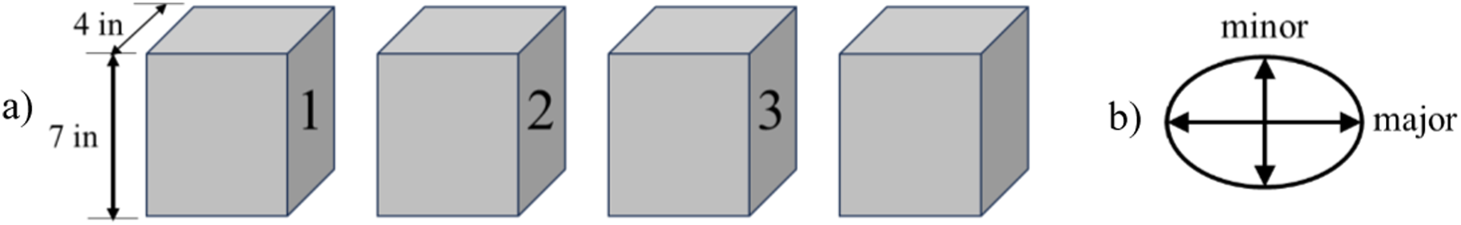
In Matlab, each image was converted to grayscale, then black and white using a grayscale threshold that turned the UHPC matrix pixels black and the steel fiber pixels white in a process described by Wagner and Lawler (2019). Because the image is a two-dimensional representation of fibers in a three-dimensional beam, a fiber oriented perpendicular to one of the cutting planes would appear in the image as a circle. However, any skewed orientation of the fiber would appear in the image as an ellipse. The Matlab script bounded each group of white pixels, representing a steel fiber, by an ellipse, and then measured the length of the major and minor axes of each ellipse in the image (Figure 7(b)). The aspect ratio of each ellipse was calculated as the length of the major axis divided by the length of the minor axis, and then the mean aspect ratio for all ellipses in an image was determined. The steel fiber aspect ratio was used to compare fiber orientation between positions along the R/UHPC beams and between R/UHPC beams with different placement methods.
Aspect ratio on both faces at each of the three cutting plane positions were analyzed and averaged across all specimens of a given placement method, i.e., either end or mid-span. An aspect ratio of 1.0 would indicate all steel fibers are oriented perpendicular to the transverse cut, whereas a higher aspect ratio would indicate fibers are inclined with respect to the cutting plane. Differences were observed between images analyzed. For example, image analysis from specimen 9.5-mid-d-1 at position 2, where it was cast, shows several ellipses and very few circular white shapes (Figure 8(a)). The average aspect ratio within this image is 2.13. For comparison, image analysis from specimen 9.5-end-d/2-1 at position 1 shows ellipses with smaller aspect ratios (Figure 8(b)). The average aspect ratio of the fibers in this image is 1.78. Fiber aspect ratio image analysis for (a) specimen 9.5-mid-d-1 at position 2 and (b) specimen 9.5-end-d/2-1 at position 1.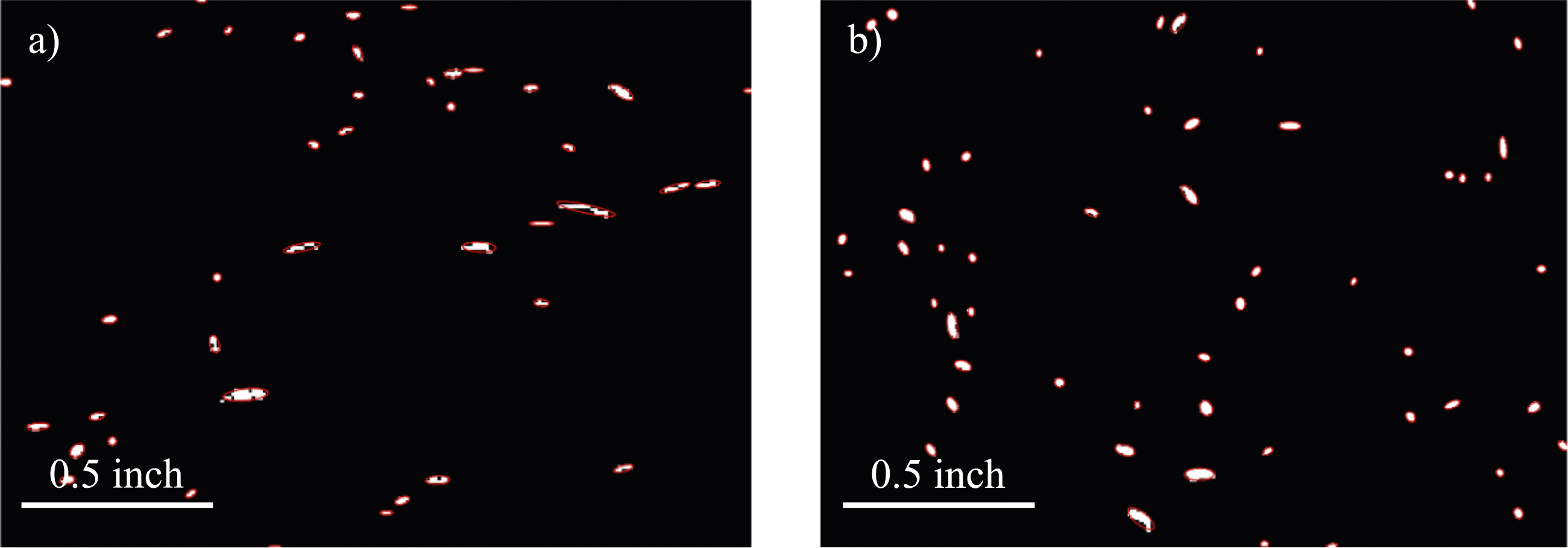
In aggregate, the mean aspect ratio results in Figure 9 show fiber orientation differed along the length of the beams and between beams with different placement methods. Specimens cast at mid-span had an average fiber aspect ratio of 1.72 at position 1. The average fiber aspect ratio increased to 1.93 at mid-span, where they were cast, then decreased to 1.86 at position 3. The 3.7% to 12% higher aspect ratio at mid-span indicates steel fibers were, in general, aligned more vertically there than the two other positions investigated. These results are consistent with (Yoo et al., 2014) that suggest fibers are more vertically aligned at the casting location, then align more horizontally as the UHPC flows to fill in the beam mold. Mean steel fiber aspect ratio at different beam positions and between beams of different placement methods.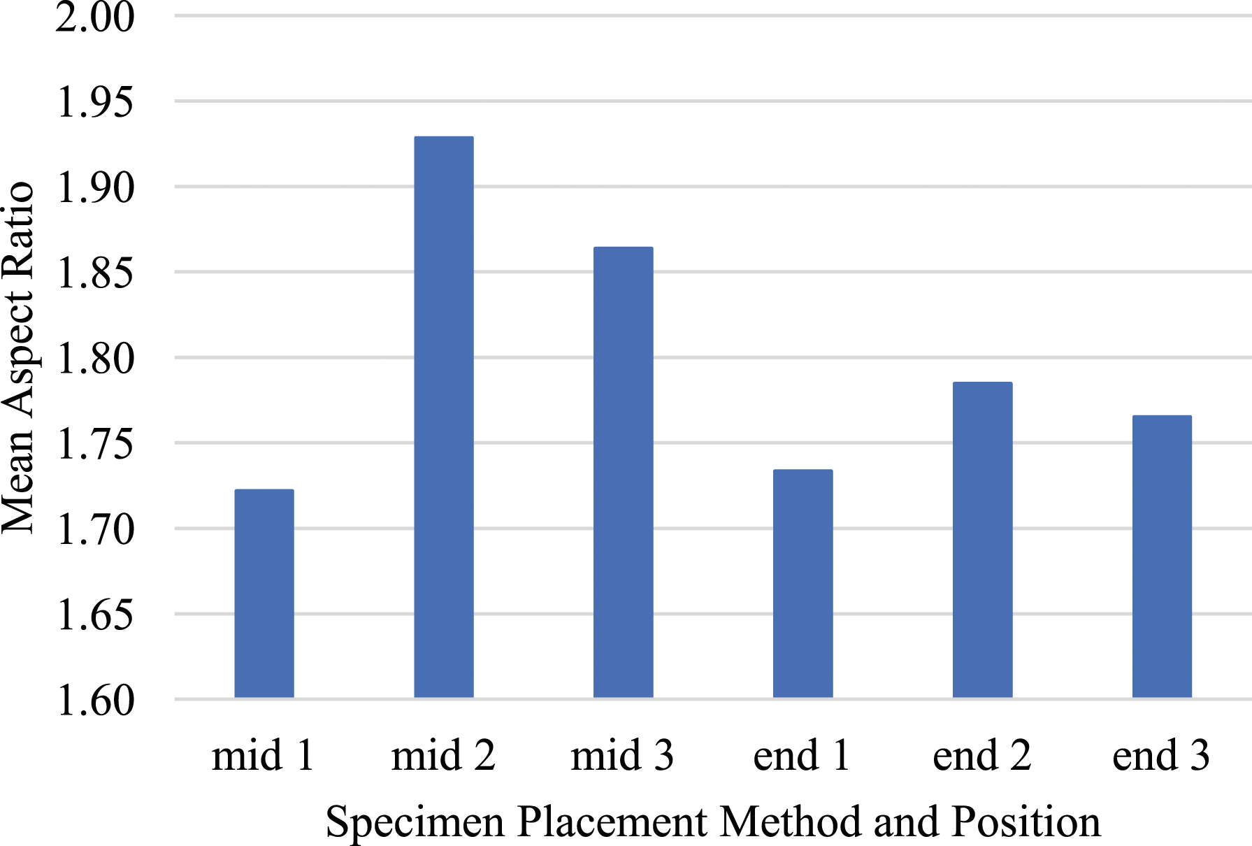
Specimens cast at the end had an average fiber aspect ratio of 1.73 at position 1, about three to four inches from where the specimen was cast. Fiber aspect ratio increased slightly at mid-span to 1.78, then decreased to 1.77 at position 3. Specimens cast at the end displayed a much more consistent fiber aspect ratio at the three positions investigated than specimens cast at mid-span. Therefore, it may be that just a few inches from the casting location (see Figure 2) may be enough distance to eliminate any significant propensity for the 0.51 inch steel fibers to orient more vertically.
Image analysis of longitudinal cuts
In addition to the above fiber orientation investigation on planes transverse to the major axis of the specimens, image analysis along the longitudinal axis was also conducted. Following the transverse cuts described in the previous section, the five R/UHPC specimens were cut longitudinally to reveal four separate faces labeled A, B, C and D (Figure 10(a)). Three specimens cast at the end (4.1-end-d-1, 4.1-end-d/2-1 and 9.5-end-d/2-1) and two specimens cast at mid-span (4.1-mid-d-1 and 9.5-mid-d-1) were investigated. (a) Longitudinal cuts in select R/UHPC beams and (b) coordinate system for fiber orientation image analysis.
Following polishing, wetting, and high-resolution photography, a Matlab script analyzed each image. Images were converted to black and white such that white pixels represented steel fibers and black pixels represented the UHPC matrix. Then, ellipses were formed around each group of white pixels. The mean orientation of all the ellipses in each image was computed. Additionally, the absolute value fiber orientation was also computed for each image by first taking the absolute value of each fiber’s angle of orientation, then taking the mean value across the image. Orientation is zero when the major axis is parallel to the positive x-axis. Values of orientation range between −90° and +90° using the sign convention shown in Figure 10(b). If a fiber has an orientation of 0°, it is perfectly horizontal, whereas deviations, either positive or negative, indicate a more upright orientation. While mean orientation reveals the average orientation of all the fibers, absolute value orientation reveals whether more fibers are consistently oriented towards a positive or negative angle, or neither. When absolute value orientation strays farther from zero, fibers are more similarly orientated to one another, a product of fiber flow and an increase in fiber alignment with each other.
Minimal differences were observed between images analyzed. In general, fiber alignment, indicated by a significant portion of the fibers in one image similarly oriented was not observed. This indicates there was not substantial unincumbered fiber flow when the UHPC was placed. In specimen 9.5-mid-d-1 at position C, image analysis reveals several ellipses oriented relatively horizontally, some at a positive angle and some at a negative angle (Figure 11(a)). The average absolute value orientation in this image is 32°. Image analysis from specimen 9.5-end-d/2-1 at position A also shows several ellipses oriented at various directions, not indicative of fiber alignment (Figure 11(b)). Due to the lack of fiber alignment with each other, it is difficult to discern a significant difference in average fiber orientation, though the average absolute value orientation in this image is 48°, or 16° larger than that of specimen 9.5-mid-d-1 at position C. Fiber orientation image analysis for (a) specimen 9.5-mid-d-1 at position (c) and (b) specimen 9.5-end-d/2-1 at position A.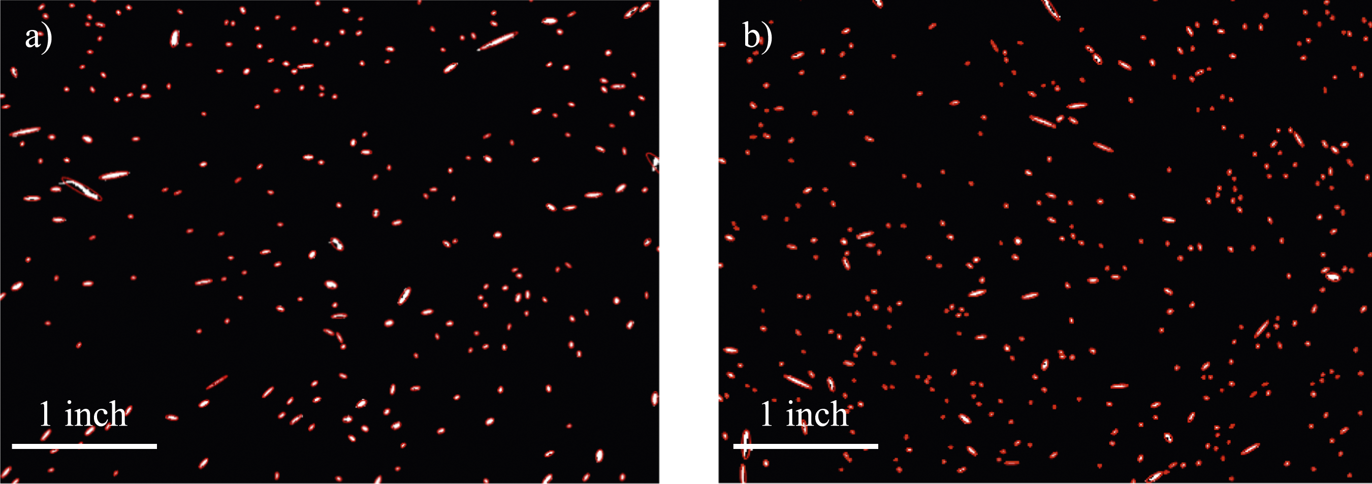
Average orientation on each of the four faces were analyzed and averaged across all specimens of a given placement method, i.e., either end or mid-span. Average orientation and average absolute value orientation results are shown in Figure 12. At every position in specimens cast with both methods investigated in this study, the mean absolute value orientation was under 45°, indicating fibers throughout the R/UHPC specimens were more horizontal than vertical. Mean steel fiber orientation at different beam positions and between beams of different placement methods.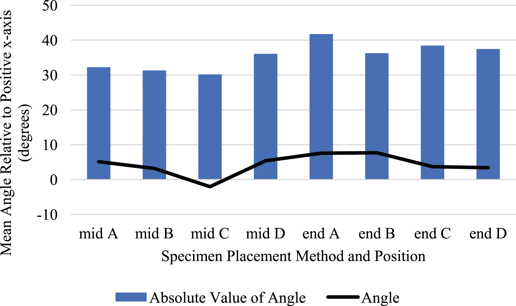
Differences between positions along the length of the beams and between beams with different placement methods were observed. Specimens cast at mid-span were cast at the juncture between faces B and C. The mean absolute value orientation of fibers at positions B (31°) and C (30°) were lower than at positions A (32°) and D (36°). These results do not indicate a more vertical alignment of fibers near the casting location, and do not support previous research findings (Yoo et al., 2014). When looking at the mean orientation angle of fibers in specimens cast at mid-span, lower values were again at positions B (3.2°) and C (−2.0°) when compared to positions A (5.1°) and D (5.4°). At positions A, B, and D, the average fiber was oriented slightly in the positive direction, however at position C, the average fiber was oriented slightly in the negative direction.
Specimens cast at the end were cast at position A. The mean absolute value orientation of fibers in specimens cast at the end were higher at every position than the fiber orientation of those cast at mid-span. The mean absolute value orientation was highest (42°) at position A, 36° at B, 38° at C, and 37° at D. With the largest absolute value orientation near the casting location, results showing a more vertical fiber orientation nearest the casting location are in agreement with Zhou and Uchida (2017) who reported that fibers in unreinforced UHPC beams align with UHPC flow direction. The average fiber was oriented slightly in the positive direction across all four positions in specimens cast at the end: 7.6° at A, 7.7° at B, 3.7° at C, and 3.4° at D. Position A in the specimens cast at the end experienced the highest mean absolute value orientation and the second highest mean orientation angle. This observation shows that fibers near the casting location were skewed from the horizontal and more likely to be skewed in the same direction from horizontal.
In both transverse and longitudinal image analyses, a greater degree of differentiation between the two placement methods was expected. However, this observation is consistent with Yoo et al. ’s (2016) conclusion that small scale beams have a favorable fiber orientation regardless of placement method. Zhou and Uchida (2017) reported that formwork can influence fiber orientation. Islam and Zhang (2023) further described the “wall effect” where fibers naturally align themselves parallel to the formwork wall within a distance of one fiber length from the wall. It is suspected that the wall effect may be extended to other objects that disrupt UHPC flow such as stirrups and longitudinal steel reinforcing bars. With a significant amount of transverse and longitudinal steel in the specimens in this study, the fiber flow could have been significantly disrupted, resulting in fibers that were not aligned with each other, and thus a fairly consistent average orientation between specimens. If confirmed with additional, full-scale specimens, the finding that transverse and longitudinal steel bars help disrupt the flow and help prevent significant differences in fiber alignment based on placement methods could be very encouraging to quell concerns about R/UHPC sensitivity to casting location or placement method.
Conclusions
The purpose of this study was to investigate shear response and capacity of R/UHPC beams. Based on a literature review, the focus of this study was on short-span beams with relatively high longitudinal reinforcement ratios and relatively low steel fiber volume fractions. Seven small scale specimens were cast and experimentally tested to failure. The specimens varied in reinforcement ratio, amount of transverse steel, fiber volume fraction, and placement methods.
Several conclusions from the tests based on the initial research questions were revealed. R/UHPC specimens with a stirrup spacing of “d/2” and 0.5% steel fibers by volume facilitated higher peak strength than specimens with a stirrup spacing of “d” and 1% steel fibers by volume. Despite only 0.5% fibers, the closer stirrup spacing provided enough shear capacity to prolong shear failure while additional load carrying capacity developed. Cracking patterns showed more multiple cracking and smaller shear crack widths in specimens with a stirrup spacing of “d/2” and 0.5% fibers when compared to those with stirrup spacing of “d” and 1% fibers. Despite being lower than many standard UHPC mixes and most UHPC studies reported in literature, DIC indicated that a 0.5% steel fiber volume fraction provided R/UHPC beams significant fiber bridging capacity across cracks in shear, compression, and tension.
When steel reinforcement ratio increased from 4.1% to 9.5% in the R/UHPC specimens, load carrying capacity generally increased, but not proportionately with the increase in steel. All specimens in this study failed in shear, and thus the full tensile capacity of the steel reinforcement was not realized at a 9.5% reinforcement ratio. Cracking patterns revealed more flexural and flexural-shear cracks formed in R/UHPC specimens as reinforcement ratio increased. Additionally, crushing cracks were more likely to form at a higher reinforcement ratio, though no spalling occurred and DIC revealed significant compression strains, even in specimens with 0.5% steel fibers by volume. Based on the specimen designs in this study, a steel reinforcement ratio of 4.1%, with stirrup spacing of “d/2” and 0.5% steel fibers by volume, was the most efficient design, meaning it provided the most balanced capacity between tension, shear, and compression capacity. Literature revealed few R/UHPC beam studies with very high steel reinforcement ratios and results herein indicate high reinforcement ratios can provide enhanced load carrying capacity as long as sufficient transverse steel is provided.
Fiber orientation in R/UHPC beams was investigated through image analysis at transverse and longitudinal planes in beams with different placement methods. Analysis on transverse planes showed that steel fibers were more likely to be skewed from perpendicular at positions nearest the casting location, but only slightly. The effects of placement method on fiber orientation are diminished just a few inches from where the beams were cast. Analysis on longitudinal planes revealed that consistent fiber alignment was not observed at any position or in specimens cast at either the end or at mid-span. It is believed that longitudinal and transverse steel interrupt fiber flow and mitigate major differences in fiber orientation due to placement method.
From these conclusions stem opportunities for additional research. Additional specimens with similar design parameters could be cast and tested to garner more data and account for natural variability. Gaps in the literature could continue to be explored with the intent of determining guidelines for a balanced approach to tensile, shear, and compression capacities of R/UHPC beams. A balanced approach for UHPC components would take advantage of UHPC’s superior properties and make for economical use of the material. Different grade and spacing of stirrups should be investigated experimentally in shear dominant beams with a steel fiber volume fraction of 0.5% and longitudinal reinforcement ratio near 4.1%. Different placement methods should continue to be explored to determine any effects on fiber orientation or subsequent beam performance. Additionally, larger-scale R/UHPC specimens should be investigated using different casting locations and placement methods. This would help provide insight to size effects, how fiber flow may be interrupted by the steel reinforcement in more realistic R/UHPC applications, and any resulting performance differences.
Supplemental Material
Supplemental Material - Investigation of shear response due to variation of fiber volume fraction, transverse steel, and placement method on short span R/UHPC beams
Supplemental Material for Investigation of shear response due to variation of fiber volume fraction, transverse steel, and placement method on short span R/UHPC beams by Timothy Frank, Peter Amaddio, Cole Landes, Darcy Farrell, Elizabeth Decko, and Alexis Tri in Advances in Structural Engineering.
Footnotes
Acknowledgments
The authors thank LafargeHolcim for their generous donation of DUCTAL material, and ChromX for their generous donation of Grade 100 reinforcement bars. This study was made possible by an Air Force Office of Scientific Research small grant.
Declaration of conflicting interests
The author(s) declared no potential conflicts of interest with respect to the research, authorship, and/or publication of this article.
Funding
The author(s) disclosed receipt of the following financial support for the research, authorship, and/or publication of this article: This work was supported by the Air Force Office of Scientific Research (USAFA Small Grant).
Disclaimer
The views expressed in this paper are those of the authors and not necessarily reflect those of the United States Air Force Academy, the Air Force, the Department of Defense, or the U.S. Government.
Supplemental Material
Supplemental material for this article is available online. The authors provide load vs. drift data for all seven specimens as well as image analysis results for both transverse and longitudinal cuts of the five specimens analyzed.
Appendix
Appendix A. Literature review summary of R/UHPC beams, select properties and response. Papers: 1. Bermudez and Hung (2019), 2. Chen et al. (2018), 3. Gomaa et al. (2021), 4. Hasgul et al. (2018), 5. Kamal et al., 2014, 6. Kodur et al. (2018), 7. Pourbaba and Alinezhad (2018), 8. Pourbaba et al. (2019), 9. Shao and Billington (2019), 10. Shao and Billington (2022), 11. Xia et al. (2018), 12. Yang et al., 2010, 13. Yang et al. (2022), 14. Yoo and Yoon (2015), 15. Yoo et al. (2017)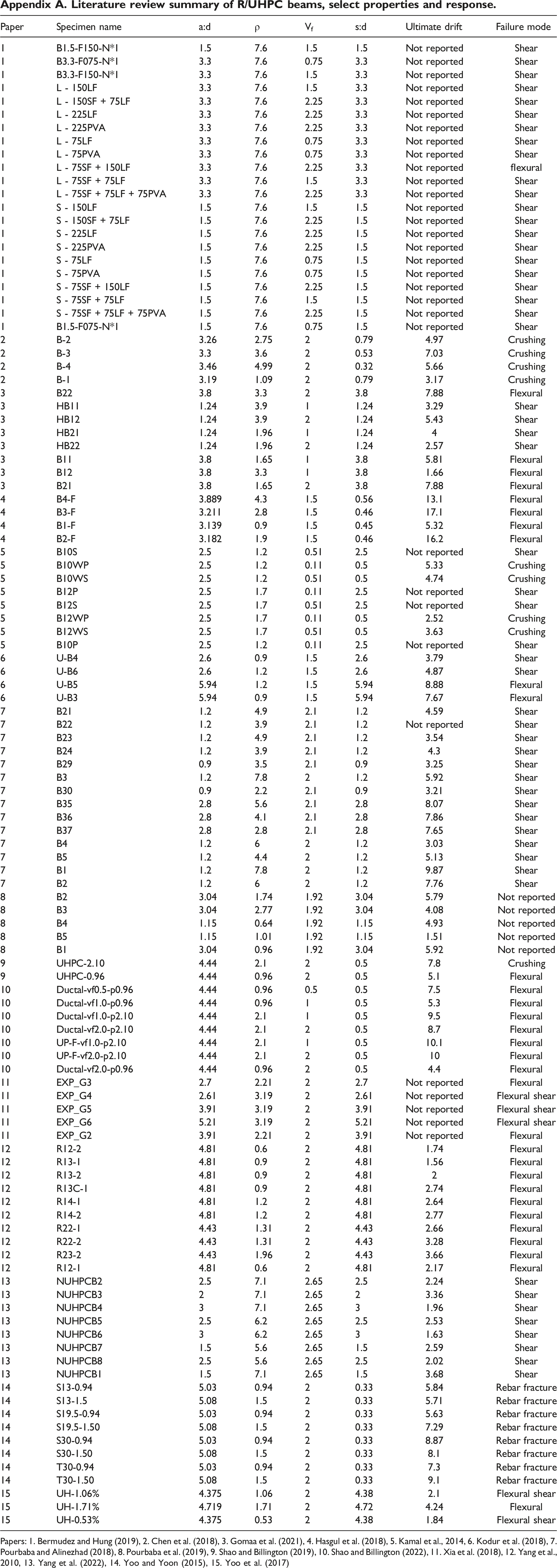
Paper
Specimen name
a:d
ρ
Vf
s:d
Ultimate drift
Failure mode
1
B1.5-F150-N*1
1.5
7.6
1.5
1.5
Not reported
Shear
1
B3.3-F075-N*1
3.3
7.6
0.75
3.3
Not reported
Shear
1
B3.3-F150-N*1
3.3
7.6
1.5
3.3
Not reported
Shear
1
L - 150LF
3.3
7.6
1.5
3.3
Not reported
Shear
1
L - 150SF + 75LF
3.3
7.6
2.25
3.3
Not reported
Shear
1
L - 225LF
3.3
7.6
2.25
3.3
Not reported
Shear
1
L - 225PVA
3.3
7.6
2.25
3.3
Not reported
Shear
1
L - 75LF
3.3
7.6
0.75
3.3
Not reported
Shear
1
L - 75PVA
3.3
7.6
0.75
3.3
Not reported
Shear
1
L - 75SF + 150LF
3.3
7.6
2.25
3.3
Not reported
flexural
1
L - 75SF + 75LF
3.3
7.6
1.5
3.3
Not reported
Shear
1
L - 75SF + 75LF + 75PVA
3.3
7.6
2.25
3.3
Not reported
Shear
1
S - 150LF
1.5
7.6
1.5
1.5
Not reported
Shear
1
S - 150SF + 75LF
1.5
7.6
2.25
1.5
Not reported
Shear
1
S - 225LF
1.5
7.6
2.25
1.5
Not reported
Shear
1
S - 225PVA
1.5
7.6
2.25
1.5
Not reported
Shear
1
S - 75LF
1.5
7.6
0.75
1.5
Not reported
Shear
1
S - 75PVA
1.5
7.6
0.75
1.5
Not reported
Shear
1
S - 75SF + 150LF
1.5
7.6
2.25
1.5
Not reported
Shear
1
S - 75SF + 75LF
1.5
7.6
1.5
1.5
Not reported
Shear
1
S - 75SF + 75LF + 75PVA
1.5
7.6
2.25
1.5
Not reported
Shear
1
B1.5-F075-N*1
1.5
7.6
0.75
1.5
Not reported
Shear
2
B-2
3.26
2.75
2
0.79
4.97
Crushing
2
B-3
3.3
3.6
2
0.53
7.03
Crushing
2
B-4
3.46
4.99
2
0.32
5.66
Crushing
2
B-1
3.19
1.09
2
0.79
3.17
Crushing
3
B22
3.8
3.3
2
3.8
7.88
Flexural
3
HB11
1.24
3.9
1
1.24
3.29
Shear
3
HB12
1.24
3.9
2
1.24
5.43
Shear
3
HB21
1.24
1.96
1
1.24
4
Shear
3
HB22
1.24
1.96
2
1.24
2.57
Shear
3
B11
3.8
1.65
1
3.8
5.81
Flexural
3
B12
3.8
3.3
1
3.8
1.66
Flexural
3
B21
3.8
1.65
2
3.8
7.88
Flexural
4
B4-F
3.889
4.3
1.5
0.56
13.1
Flexural
4
B3-F
3.211
2.8
1.5
0.46
17.1
Flexural
4
B1-F
3.139
0.9
1.5
0.45
5.32
Flexural
4
B2-F
3.182
1.9
1.5
0.46
16.2
Flexural
5
B10S
2.5
1.2
0.51
2.5
Not reported
Shear
5
B10WP
2.5
1.2
0.11
0.5
5.33
Crushing
5
B10WS
2.5
1.2
0.51
0.5
4.74
Crushing
5
B12P
2.5
1.7
0.11
2.5
Not reported
Shear
5
B12S
2.5
1.7
0.51
2.5
Not reported
Shear
5
B12WP
2.5
1.7
0.11
0.5
2.52
Crushing
5
B12WS
2.5
1.7
0.51
0.5
3.63
Crushing
5
B10P
2.5
1.2
0.11
2.5
Not reported
Shear
6
U-B4
2.6
0.9
1.5
2.6
3.79
Shear
6
U-B6
2.6
1.2
1.5
2.6
4.87
Shear
6
U-B5
5.94
1.2
1.5
5.94
8.88
Flexural
6
U-B3
5.94
0.9
1.5
5.94
7.67
Flexural
7
B21
1.2
4.9
2.1
1.2
4.59
Shear
7
B22
1.2
3.9
2.1
1.2
Not reported
Shear
7
B23
1.2
4.9
2.1
1.2
3.54
Shear
7
B24
1.2
3.9
2.1
1.2
4.3
Shear
7
B29
0.9
3.5
2.1
0.9
3.25
Shear
7
B3
1.2
7.8
2
1.2
5.92
Shear
7
B30
0.9
2.2
2.1
0.9
3.21
Shear
7
B35
2.8
5.6
2.1
2.8
8.07
Shear
7
B36
2.8
4.1
2.1
2.8
7.86
Shear
7
B37
2.8
2.8
2.1
2.8
7.65
Shear
7
B4
1.2
6
2
1.2
3.03
Shear
7
B5
1.2
4.4
2
1.2
5.13
Shear
7
B1
1.2
7.8
2
1.2
9.87
Shear
7
B2
1.2
6
2
1.2
7.76
Shear
8
B2
3.04
1.74
1.92
3.04
5.79
Not reported
8
B3
3.04
2.77
1.92
3.04
4.08
Not reported
8
B4
1.15
0.64
1.92
1.15
4.93
Not reported
8
B5
1.15
1.01
1.92
1.15
1.51
Not reported
8
B1
3.04
0.96
1.92
3.04
5.92
Not reported
9
UHPC-2.10
4.44
2.1
2
0.5
7.8
Crushing
9
UHPC-0.96
4.44
0.96
2
0.5
5.1
Flexural
10
Ductal-vf0.5-p0.96
4.44
0.96
0.5
0.5
7.5
Flexural
10
Ductal-vf1.0-p0.96
4.44
0.96
1
0.5
5.3
Flexural
10
Ductal-vf1.0-p2.10
4.44
2.1
1
0.5
9.5
Flexural
10
Ductal-vf2.0-p2.10
4.44
2.1
2
0.5
8.7
Flexural
10
UP-F-vf1.0-p2.10
4.44
2.1
1
0.5
10.1
Flexural
10
UP-F-vf2.0-p2.10
4.44
2.1
2
0.5
10
Flexural
10
Ductal-vf2.0-p0.96
4.44
0.96
2
0.5
4.4
Flexural
11
EXP_G3
2.7
2.21
2
2.7
Not reported
Flexural
11
EXP_G4
2.61
3.19
2
2.61
Not reported
Flexural shear
11
EXP_G5
3.91
3.19
2
3.91
Not reported
Flexural shear
11
EXP_G6
5.21
3.19
2
5.21
Not reported
Flexural shear
11
EXP_G2
3.91
2.21
2
3.91
Not reported
Flexural
12
R12-2
4.81
0.6
2
4.81
1.74
Flexural
12
R13-1
4.81
0.9
2
4.81
1.56
Flexural
12
R13-2
4.81
0.9
2
4.81
2
Flexural
12
R13C-1
4.81
0.9
2
4.81
2.74
Flexural
12
R14-1
4.81
1.2
2
4.81
2.64
Flexural
12
R14-2
4.81
1.2
2
4.81
2.77
Flexural
12
R22-1
4.43
1.31
2
4.43
2.66
Flexural
12
R22-2
4.43
1.31
2
4.43
3.28
Flexural
12
R23-2
4.43
1.96
2
4.43
3.66
Flexural
12
R12-1
4.81
0.6
2
4.81
2.17
Flexural
13
NUHPCB2
2.5
7.1
2.65
2.5
2.24
Shear
13
NUHPCB3
2
7.1
2.65
2
3.36
Shear
13
NUHPCB4
3
7.1
2.65
3
1.96
Shear
13
NUHPCB5
2.5
6.2
2.65
2.5
2.53
Shear
13
NUHPCB6
3
6.2
2.65
3
1.63
Shear
13
NUHPCB7
1.5
5.6
2.65
1.5
2.59
Shear
13
NUHPCB8
2.5
5.6
2.65
2.5
2.02
Shear
13
NUHPCB1
1.5
7.1
2.65
1.5
3.68
Shear
14
S13-0.94
5.03
0.94
2
0.33
5.84
Rebar fracture
14
S13-1.5
5.08
1.5
2
0.33
5.71
Rebar fracture
14
S19.5-0.94
5.03
0.94
2
0.33
5.63
Rebar fracture
14
S19.5-1.50
5.08
1.5
2
0.33
7.29
Rebar fracture
14
S30-0.94
5.03
0.94
2
0.33
8.87
Rebar fracture
14
S30-1.50
5.08
1.5
2
0.33
8.1
Rebar fracture
14
T30-0.94
5.03
0.94
2
0.33
7.3
Rebar fracture
14
T30-1.50
5.08
1.5
2
0.33
9.1
Rebar fracture
15
UH-1.06%
4.375
1.06
2
4.38
2.1
Flexural shear
15
UH-1.71%
4.719
1.71
2
4.72
4.24
Flexural
15
UH-0.53%
4.375
0.53
2
4.38
1.84
Flexural shear
References
Supplementary Material
Please find the following supplemental material available below.
For Open Access articles published under a Creative Commons License, all supplemental material carries the same license as the article it is associated with.
For non-Open Access articles published, all supplemental material carries a non-exclusive license, and permission requests for re-use of supplemental material or any part of supplemental material shall be sent directly to the copyright owner as specified in the copyright notice associated with the article.