
Abstract
This study aims to experimentally and numerically investigate the behavior of reinforced concrete (RC) beams designed to exhibit flexure and shear failure behavior by changing the shear reinforcement ratio, which has undergone different corrosion rates under the effect of impact loading. Corrosion is the damage type that affects RC members the most throughout their economic life due to environmental conditions. Studies in literature examine the behavior of corroded RC beams under the effect of static and reversible repeated dynamic loads such as earthquakes or wind. However, the literature does not present a comprehensive experimental study examining the behavior of corroded RC beams under the effect of sudden dynamic impact loads. The planned study selects the corrosion percentage of RC beams and the status of exhibiting shear or flexural failure as experimental variables in a design approach. Acceleration, displacement, and loading time changes under the impact loading applied to corroded RC beams are measured and evaluated with the authors’ free weight drop test setup. The beams’ collapse mechanisms and energy dissipation capacities are interpreted, and the effects of corrosion on the behavior of the beams under the impact loading are investigated. The results obtained from the experimental part of the study and the numerical analysis results performed with the Ls-Dyna finite element software are compared, and the extent to which successful FEA analyses could be obtained is interpreted. It is observed that the corrosion occurring in RC beams negatively affected behavior under the impact loading significantly, reduced the maximum acceleration values measured from the beams by an average of 118%, and increased the maximum displacement and permanent residual displacement values occurring under the applied impact loading effect by an average of 142% and 167%, respectively. Corrosion also negatively affected the energy dissipation capacities of RC beams under the impact loading effect significantly and caused an average decrease of 81%.
Introduction
Corrosion is one of the major causes of significant deterioration in Reinforced Concrete (RC) structures. Reinforcing steel corrosion is arguably the most extensive problem, particularly when exposed to aggressive environments of the various deterioration mechanisms affecting RC structures. As steel bars corrode, the cross-sectional areas of the reinforcing bars decrease, and the corrosion products (rust) with higher volume surround the steel reinforcement. The rust exerts tensile forces on the surrounding concrete, causing deep splitting cracks. Hence, the bond stress between the steel reinforcement and concrete will deteriorate (Al-Saidy and Al-Jabri 2011; Almusallam, 2001). Besides, the reduction in the cross-section of steel reinforcement may lead to dramatic decreases in the flexural capacity and stiffness of the RC member (Liu et al., 2016). Fortunately, destructive corrosion is normally a long process and can be stopped if preventive measures are implemented as soon as the early signs of corrosion are detected (Liu et al., 2022a; Liu et al., 2022a; Stewart et al., 2012; Stewart and Peng, 2010). Chloride-induced corrosion, particularly, is a well-studied issue affecting coastal structures such as wharf columns, bridge girders, beams, and piers. The main deterioration mechanisms of RC members that are exposed to aggressive chloride-induced corrosion environments include (1) loss of cross-sectional area and degradation of yield strength of rebar due to the pitting, (2) deterioration of bond-slip between rebar and concrete due to the corrosion products, and (3) generation of rust expansive pressure that caused cracking, spalling and delaminating of the concrete cover (Liu et al., 2022c). Owing to the detrimental consequences of corrosion damage, understanding the post-corrosion hazard resistance of RC members is necessary for reliable evaluation of structural performance, determination of repair methods, development of durable maintenance technologies, and prediction of the service life of the structures. Corrosion is one of the most important causes of damage to RC members due to environmental reasons. Therefore, this issue has been given importance in literature, and many studies have been conducted on it. In these studies, the damages that RC members receive due to corrosion, general load displacement behaviors, load carrying capacity, stiffness, displacement ductility ratios, decrease in energy dissipation rates, and how negative effects are affected by corrosion have been examined. However, in most of these studies, the general behaviors of corroded RC members under the effect of monotonic static loads or reversal cyclic dynamic loads such as earthquakes and winds of longer duration have been investigated. No comprehensive study has been found in the literature examining the behaviors of corroded RC members under the effect of sudden dynamic impact loading. Studies aimed at improving the mechanical properties of concrete by adding different fibers and additives to the concrete in order to reduce and prevent damage and load-bearing capacity deficiencies that may occur on reinforced concrete structural elements due to corrosion and similar reasons are also found in the literature. However, it has been observed that these studies also examine the behavior of reinforced concrete structural elements under the effect of static loads (Elkhouly et al., 2025; Hamoda et al., 2024, 2025; Mim et al., 2025).
It is shown that a section’s dynamic impact loading response can differ significantly from conventional static, quasi-static, or cyclic loading conditions. Corroded RC structures may undergo low-velocity impact loads as a dynamic load within their designed service life. For example, marine structures adjacent to tidal zones may be subject to impact loads. Furthermore, collisions between vehicles and bridges occur periodically. Most studies regard quasi-static loading or low-rate reversal cyclic dynamic loading, as often occurs during seismic events (Choe et al., 2009; Inci et al., 2013; Ma et al., 2012; Yalciner et al., 2012). However, there has been little research on corroded RC members under the influence of high-rate impact loads that may occur during different conditions. These conditions can be vehicles hitting corroded highway bridge beams, marine vehicles hitting corroded seaway bridge beams, hits by objects brought by waves, structures being hit by falling rocks, and hits by objects brought by landslides and floods. For example, rock sheds and protective retaining walls are typical RC structures to which impact loads are applied. Whereas these structures are typically designed to maintain a sufficient margin of safety in their initial condition, the effects of long-term deterioration on safety are unclear. For example, these structures are often installed along the coast directly below a steep terrain, making them susceptible to salt-enhanced corrosion damage. Among RC members, especially in highway and sea bridges, it is very common for RC beams to be subject to corrosion during the economic life of the bridges. It is an extremely important research topic to know the capacities and general behaviors of these beams that have been corroded due to changing and increasing traffic loads under the impact loads that may occur. In the comprehensive literature review, it is seen that there are very few studies on this subject and that there is no comprehensive research. Therefore, an experimental study is planned on the behaviors of corroded RC beams at different rates under the effect of sudden dynamic impact loads. The research on corroded RC members subjected to impact and blast loads is very limited. Tamai et al., 2020 deployed the experimental tests of RC beams with various corrosion degrees subjected to drop weight impact. They concluded that the pre-existing corrosion-induced cracks mainly influence the decreased impact resistance of RC beams. Liu et al., 2022d performed the fragility analysis of the corroded RC columns under blast loads using Monte Carlo simulation and quantified the increment of blast damage with corrosion effect. It is well-known that the analysis and design of RC members under quasi-static and low-rate dynamic loads cannot be directly applied to the design of members subjected to impact loads (Hao et al., 2016; Pham et al., 2018). In this regard, the nonlinear response of corroded RC members under high-rate impact loads involving stress wave propagation in the members is more complex and time-dependent. This makes some simplified approaches in modeling the corrosion effect not necessarily led to reliable response predictions of corroded RC members. Therefore, there is a need to investigate the nonlinear response of corroded RC members under impact loads and predict the behavior of RC beams with different corrosion degrees. Liu et al., 2023 used the experimental study results by Tamai et al., 2020 to validate the numerical analysis model they created to obtain the behavior of corroded beams. Based on the validated model, the finite element (FE) models of corroded RC columns with a maximum corrosion degree of 15% were established, and their responses and damage to blast loads in various blasting scenarios were calculated. It is found that the blast response of the column increases with the degree of corrosion. The blast damage mode may change from combined shear and flexural damage to concrete spalling damage with the increment of corrosion degree. Furthermore, the residual axial loading capacity and stiffness of post-blast columns were calculated, and they were found to degrade as the corrosion degree increased. Daneshvar et al., 2021 investigated the behavior of corroded RC slabs under impact loading. This paper investigated the dynamic behavior of RC slabs with corroded reinforcement and evaluated the effects of strengthening using externally bonded Fiber Reinforced Polymer (FRP). Five RC slabs of 1100 × 450 × 60 mm were subject to accelerated corrosion using a constant current technique. One control slab, two corroded, and two strengthened corroded slabs were tested under low-velocity impact loads. A simple yet practical macro-scale Finite Element (FE) model is developed and validated using the experimental results with an average error of 10 and 13% for positive and negative peak acceleration, respectively. The FE model employed concrete damage plasticity and accounted for the steel mass losses and the volumetric changes of the corrosion products. Finally, a parametric study quantified the relations between the carbon FRP strengthening ratio and the corrosion levels.
As stated above, as a result of the comprehensive literature review, an extremely limited number of studies are found examining the behavior of corroded RC beams under sudden dynamic impact loading. Except for the study conducted by Tamai et al., 2020, no other study has examined the behavior of corroded RC beams under impact loading. For this reason, an experimental study is planned to examine the behavior of corroded RC beams at different rates under impact loading. In the experimental study, the effect of corrosion percentage is inspected with the design of RC beams in 2 different failure types: shear and flexural failure. In other words, RC beam specimens are designed in two groups. The first group is intended to have a shear failure under loading, while the other group is intended to have a flexural failure. So, the effect of corrosion in these two failure types can be seen separately and compared. The impact loading design for corroded RC beams is carried out with a free weight drop test setup made by the authors, and acceleration-time, displacement-time, and applied impact loading-time measurements are taken on the beams. In addition, the beams’ collapse mechanisms and energy dissipation capacities are also interpreted, and the effects of the variables are examined in the experimental study on the behavior of corroded RC beams under impact loading. Then, the tested corroded RC beams within the experimental study’s scope are analyzed using the numerical analysis model. It is performed with Ls-Dyna FE software. Results of the experimental study and the FE analysis are compared to see the extent of the FE analysis models of corroded RC beams, and it is seen that the FE analysis gave successful results compared to the experimental study.
Experimental study
Test specimens and materials
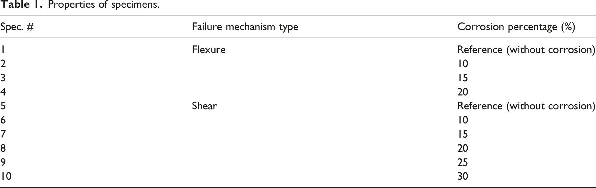
Properties of specimens.
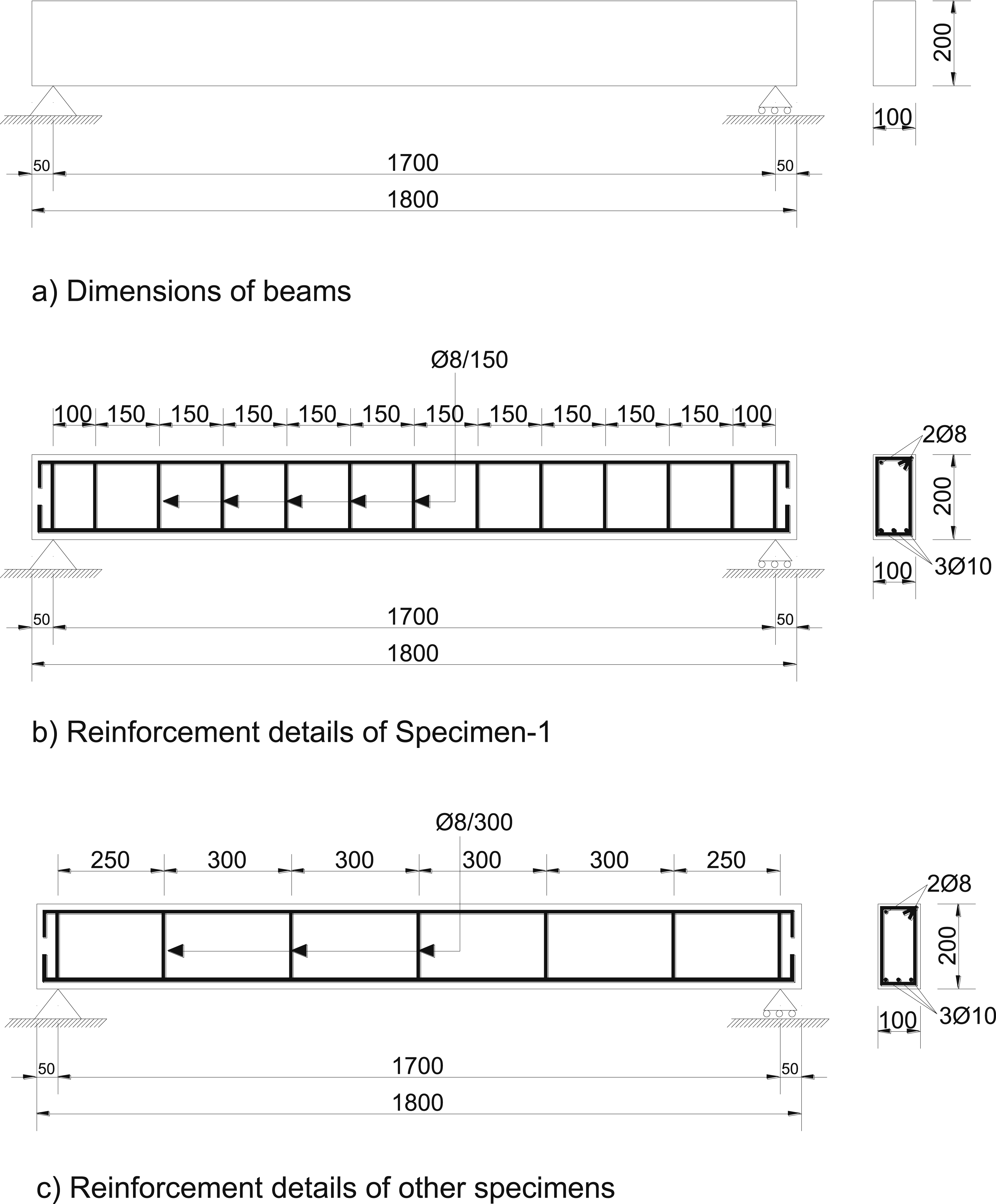
Dimensions and reinforcement details of specimens (Dimensions in mm.).
When the reinforcement details given in Figure 1 are examined, it is seen that there are differences in the reinforcement details of the RC beams that are intended to exhibit bending failure and the beams that are intended to exhibit shear failure. Shear reinforcement is placed at 150 mm intervals in the beams intended to exhibit bending failure and at 300 mm intervals in the beams intended to exhibit shear failure. Molds are prepared for the number of specimens, aiming to produce all specimens simultaneously for concrete casting of reinforced concrete beams. First, the reinforcement cages of the RC beams are prepared, as detailed in Figure 1. For the accelerated corrosion test system to be applied later, cables are connected to the longitudinal reinforcements of the beams to transmit electricity and arranged so that they would not be damaged during concrete pouring. After the prepared reinforcement cages are placed in the molds, paying attention to the allowances, concrete is poured using ready-mixed concrete. Examples selected from the photographs taken during the production of the test elements are given in Figure 2. Selected examples from photographs taken during the manufacturing of specimens.
C35 concrete is supplied as ready-mixed concrete and standard cube samples with dimensions of 150 × 150 × 150 mm is taken from the ready-mixed concrete to cast the test elements to produce the specimens. Cube concrete samples and RC beams produced as specimens are stored under the same curing conditions. The concrete compressive strengths of the specimens are determined by testing 11 concrete cube test elements taken after the 28-day curing period, and the concrete compressive strengths obtained from the tests of the cube samples varied between 33.47 MPa and 35.11 MPa. The average concrete compressive strength value of RC specimens is 34.67 MPa. The cube concrete samples are tested with a computer-controlled concrete press with a constant loading speed fixed at 0.1 mm/sec to determine the compressive strength of the specimens. The equipment used to produce the specimens is provided at once to ensure their mechanical properties are identical. In producing the specimens, 8 mm diameter deformed bars are used as shear reinforcement and assembly reinforcement, and 10 mm deformed bars are used as longitudinal reinforcement. Three samples from each reinforcement are taken, and an axial tensile test is applied to determine the mechanical strength values of two different types of reinforcement. Axial tensile tests of the reinforcement are carried out using a computer-controlled testing system, and the loading rate is fixed at 0.1 mm/sec. The yield strength, tensile strength, and elastic modulus values of 8 mm diameter deformed bars are 427 MPa, 516 MPa, and 201 GPa, respectively. Yield strength, tensile strength, and elastic modulus values for 10 mm diameter deformed bars are determined as 433 MPa, 528 MPa, and 202 GPa, respectively.
After the production and curing periods of the RC beam specimens are completed, the process of inflicting accelerated corrosion damage on the beams is carried out. Necessary information about the test system and procedure used to assess beam corrosion damage is briefly summarized below. First, the stirrups and longitudinal reinforcement used in the production of each beam are weighed, and the total reinforcement weights are determined. The average reinforcement weights for bending and shear failure beams are 6600 g and 6300 g, respectively. Then, the beam samples are corroded until a theoretical weight loss of 10%, 15%, 20%, 25% and 30% occurred at these determined weights. Since the electric current used to cause corrosion damage to RC beams is chosen as constant, the corrosion test times required to achieve the desired theoretical weight loss are determined by the Faraday equation before starting the experiment. The constant corrosion current is chosen as 1.0 ampere. The Faraday equation given in equation (1) is used to determine the time required to achieve theoretical weight losses. The experiments are terminated after applying an electric current at the selected constant ampere value for the calculated periods for the theoretical weight losses to reach 10%, 15%, 20%, 25%, and 30%.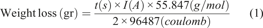
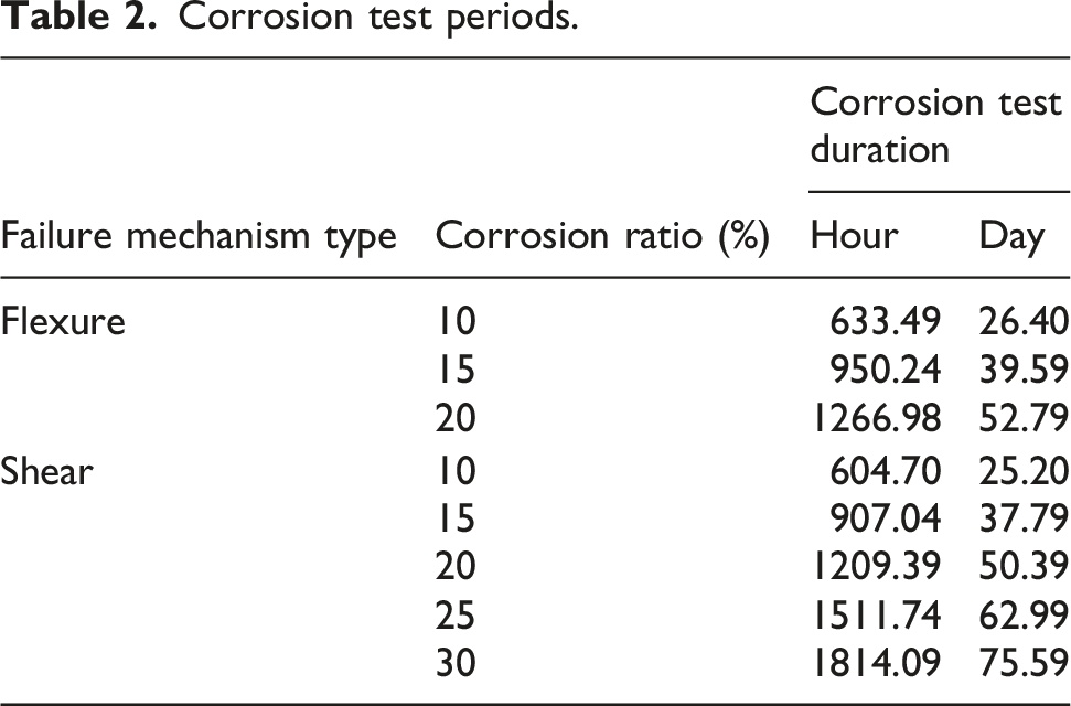
Corrosion test periods.

Accelerated corrosion application test setup of specimens.
The reinforcements in the beam (working electrode) are connected to the positive pole of the direct current source, which applies 1.0 Ampere constant current to the system, and the stainless-steel plate (counter electrode) is connected to the negative pole. In this circuit, the reinforcement in the beam serves as the anode, the stainless-steel plates serve as the cathode, and the NaCl solution serves as the electrolyte. In the corrosion process of the beams, one beam is connected to a DC power source. The test elements, which are left in the test apparatus designed for the corrosion process for the periods given in Table 2, are removed after the period is completed and tested by applying impact loading directly with the free-weight test apparatus without any operation on them.
Test setup and instrumentations
Impact loading on the RC beam specimens is applied using a free drop weight test setup designed by the authors, which is previously used in many studies in the literature (Yılmaz et al., 2022). The details of the experiment and measurement setup used in the experimental study are presented in Figure 4. A constant energy impact load of 2.2367 kJoule is applied to the RC beam specimens by dropping a 152 kg impactor from a height of 1.5 m. The dimensions of the RC beams tested in the experimental study were determined by considering the capacity of the free-weight test setup used for the tests and the measurement capacities of the sensors used in the measurements. The geometric dimensions of the tested RC beams were also selected according to the impact loading energy magnitude that can be applied in the test setup. A reasonable specimen size has been determined to sustain damage that can be monitored at the energy level of the applied impact loading and where the differences caused by the variables examined in the experimental study can be monitored. In addition, the geometry of the RC beam specimens is determined by considering the sensitivities and capacities of the measurement sensors used in the experimental study. The dimensions of the steel support system used were determined according to the geometric dimensions of the RC beams tested in the experimental study, and the support system is produced using high-strength ST52 class structural steel. Impact loading test setup and instrumentations.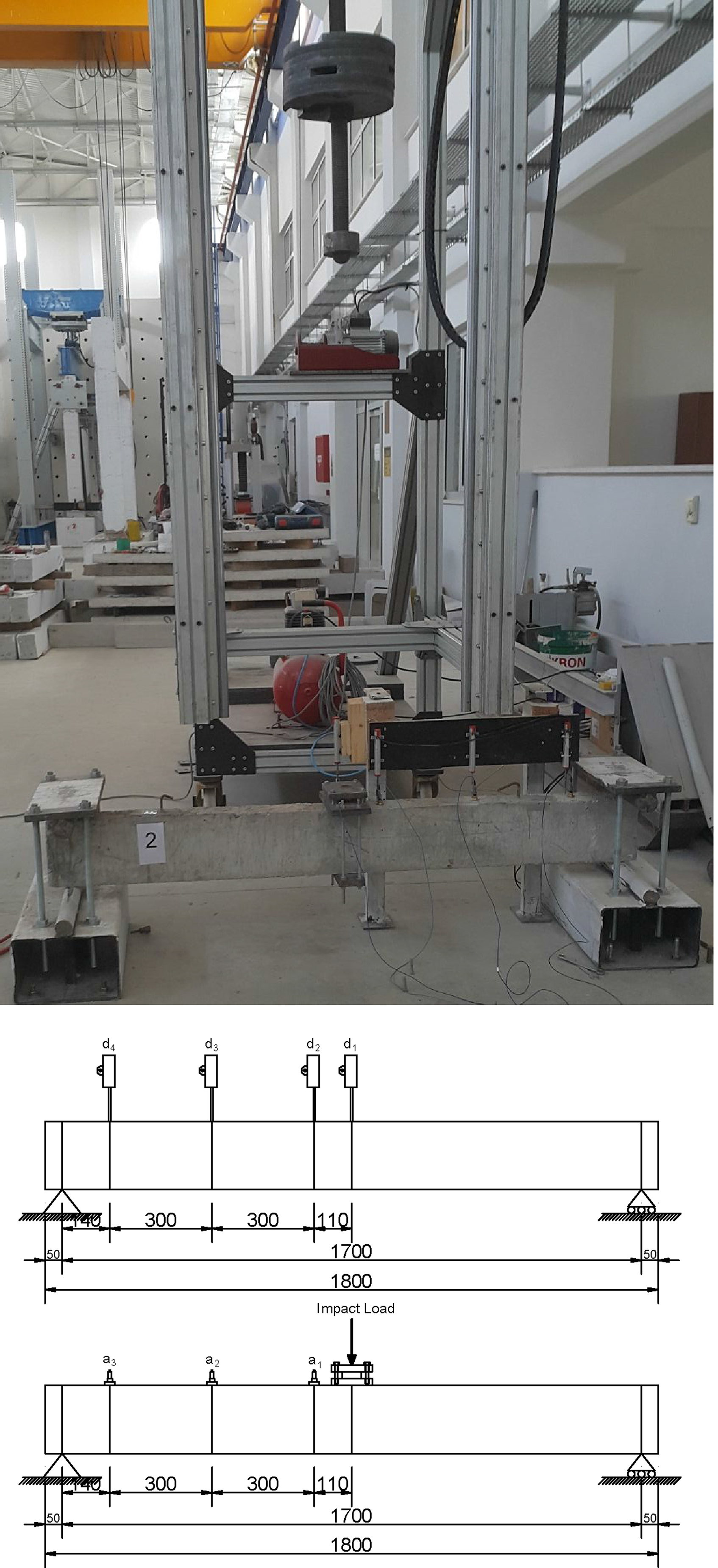
Impact loading on the RC beams is applied and measured by a dynamic load cell between two high-strength steel plates placed exactly at beam midpoints. Placing the dynamic load cell between two steel plates protects the specimens, and the impact load is applied to all specimens from the same point and distributed to an identical area, thus preventing any possible eccentricity during loading. Details about the positions of the steel plates with a dynamic load cell placed on the specimens and the locations of other acceleration and displacement sensors according to the position of these plates are given in Figure 4. A high-strength two steel loading plates with dimensions of 150 × 200 × 15 mm was placed at the application point of impact load so that the impact loading could be acted on the entire beam section. The dynamic load cell is placed between these two steel loading plates and connected to the midpoint of the beam. Impact loads were applied to the mid-span of the RC beams. RC beam specimens were placed on a support system composed of steel profiles, which can be assumed as simply support at both ends, preventing their horizontal and vertical movements but enabling them to rotate freely. An impactor head of high-strength steel with hemispherical geometry is used to apply the constant energy impact load to the specimens. The acceleration-time, displacement-time, and impact loading-time histories that occurred due to the application of impact load to the RC beam specimens were measured and interpreted. By measuring the acceleration from 3 points and the displacement from 4 points from each of the RC beam specimens, it is aimed to investigate how the displacement and acceleration varied in the RC beams due to the application of the impact load are distributed and how their changes occur as we move away from the impact point. RC beams were placed on a support setup made of steel profiles and supported on two sides to be accepted as hinge support. Hinge supports were placed 50 mm inside from both ends of the RC beams, and the beams were supported by compressing them using rollers so that they could rotate freely in the middle of two high-strength steel plates.
The impact loading transferred to the specimens was measured with a dynamic load cell connected to RC beam mid-point between two steel plates. For each RC beam, three acceleration, four displacements, and one impact load time history, eight measurements were taken with the frequency of 10 kHz, transferred via a dynamic data acquisition system to the computer, and recorded. For acceleration measurements, three Model 352B70 piezoelectric ICP-type accelerometers from PCB Group were used (Figure 5(a)). The selection of mounting method considered location, amplitude range, strength, accessibility, temperature, and portability. According to tests by the manufacturer (Figure 5(b)), screw mounting was preferred for optimal high frequency response. Holes were drilled into the RC beams and steel dowels were inserted to secure the brass mounting apparatus, ensuring precise measurements. Displacement profiles were captured using four Opkon SLPS 100 D 5K 10 M potentiometers (Figure 5(g)), with specifications including 100 mm stroke, ±0.2% linearity, <0.01 mm repeatability, infinite resolution, and 5 kOhm resistance. Data acquisition was performed using National Instruments systems: NI 9234 for accelerations (Figure 5(c)) and NI 9201 for displacements (Figure 5(d)), connected to an eight-channel sensor supply box (Figure 5(e)) and integrated into a cDAQ-9174 chassis (Figure 5(f)). Measurements were recorded and calibrated via LabVIEW Signal Express software. Low-noise PCB 003A10 coaxial cables were used for signal transmission (Figure 5(h)). (a) ICP-type accelerometer (PCB 352B70), (b) mounting methods of accelerometers and sensitivity-duration curves, (c) NI 9234 accelerometer data acquisition module, (d) NI 9201 displacement data acquisition module, (e) cDAQ-9174 compact data acquisition chassis, (f) multi-channel data acquisition system prepared for testing, (g) potentiometric displacement transducer, and (h) low-noise coaxial cable with structural components.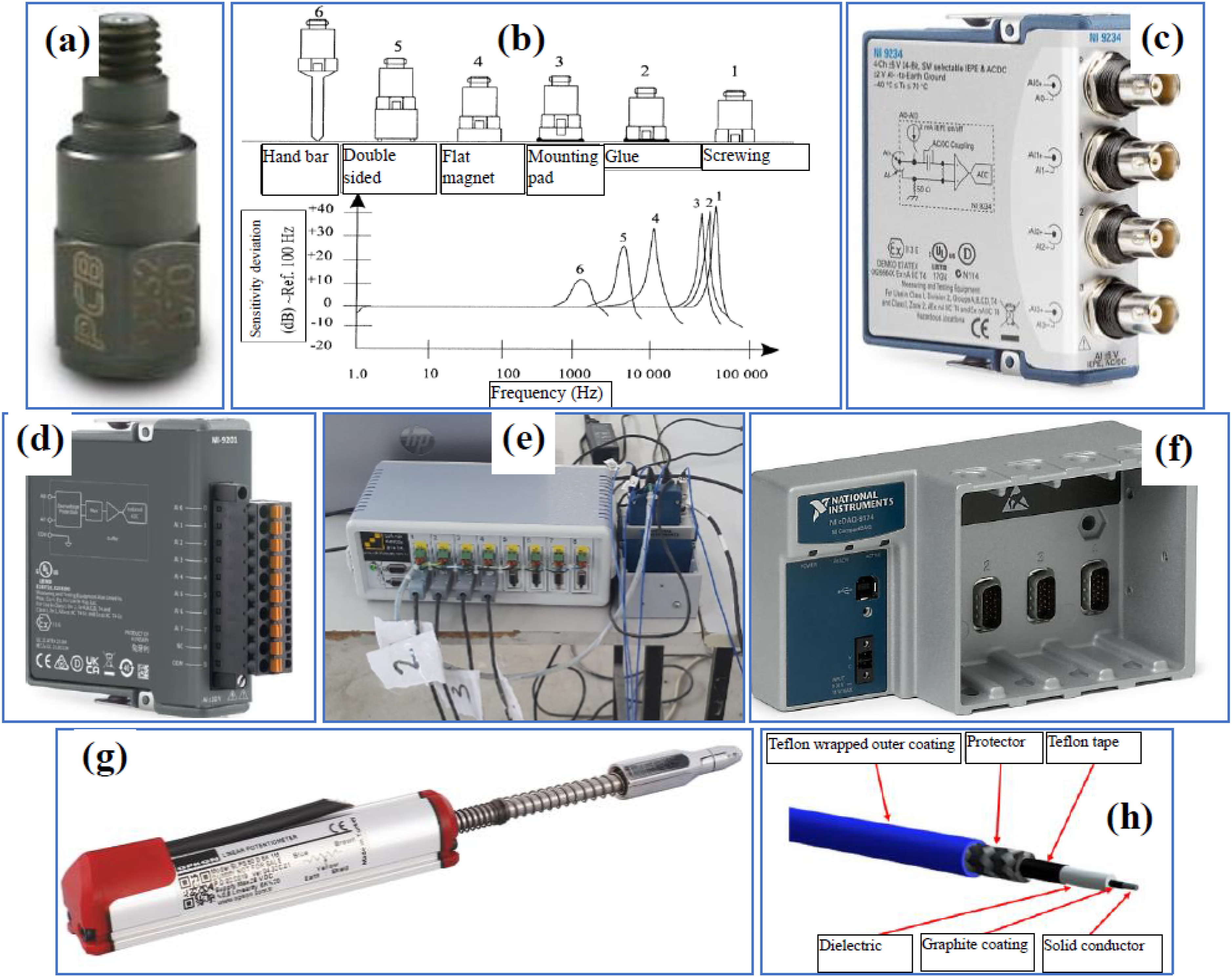
Experimental results and discussions
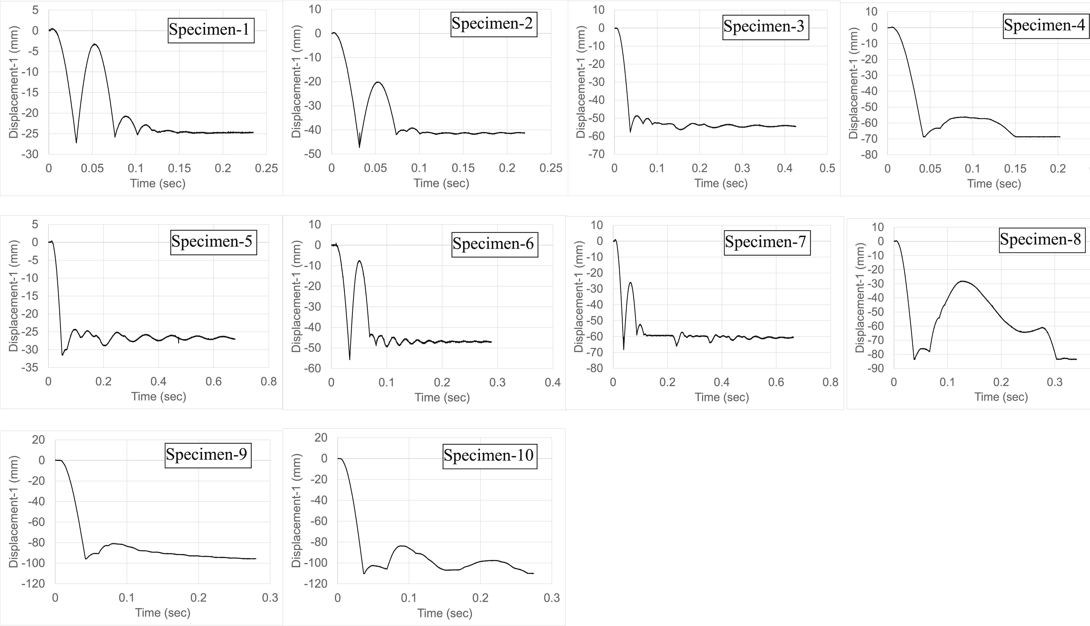
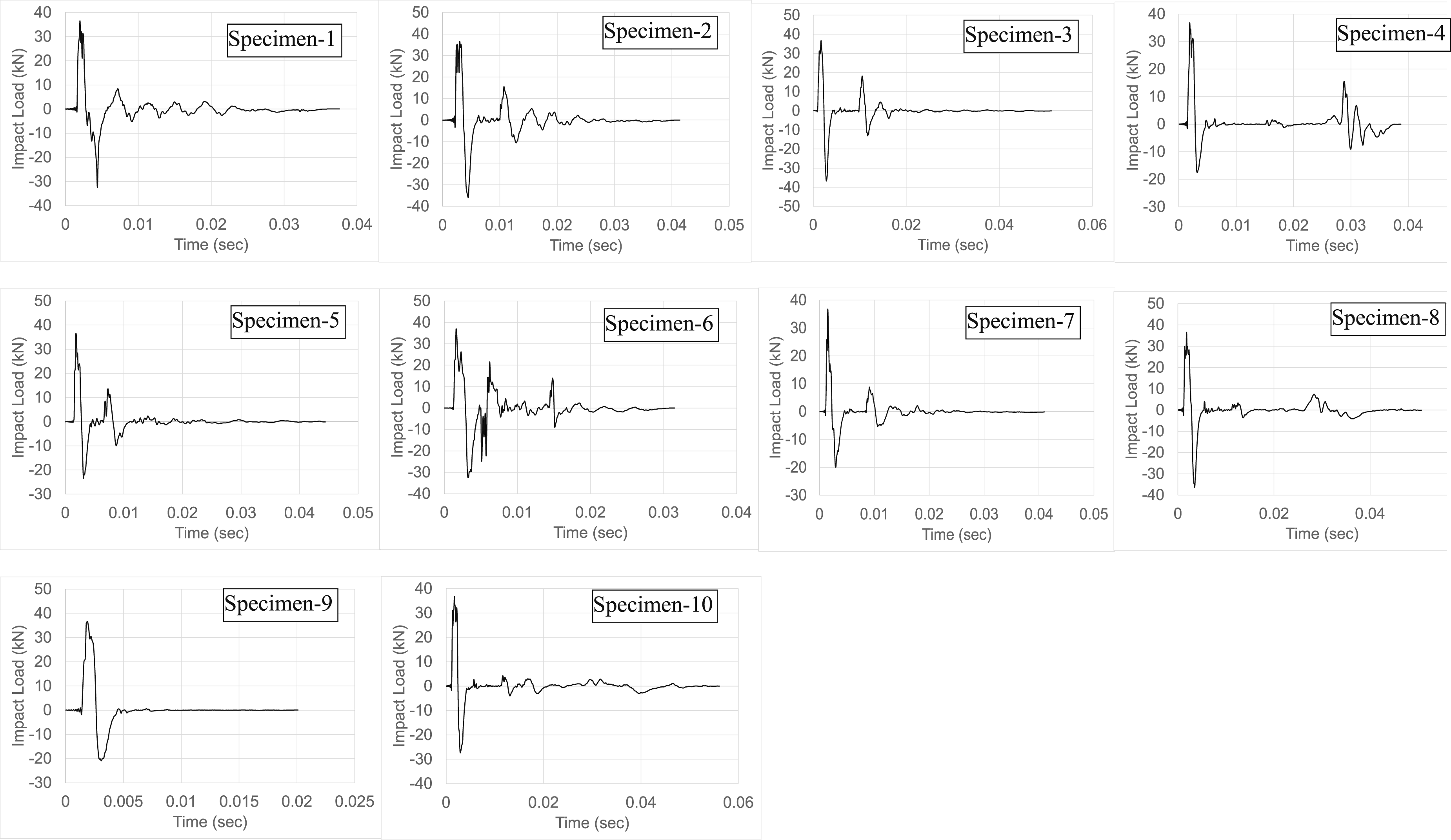
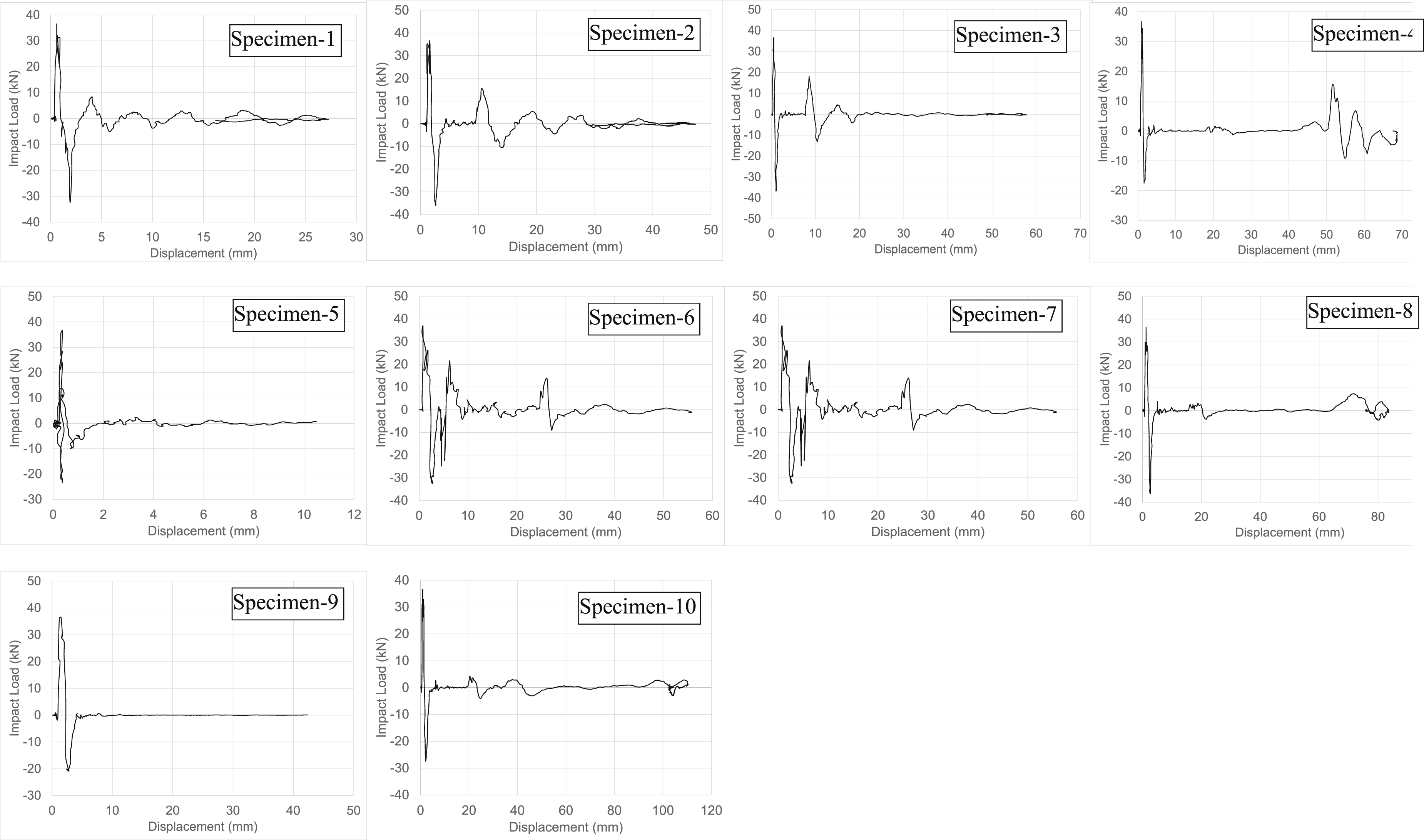
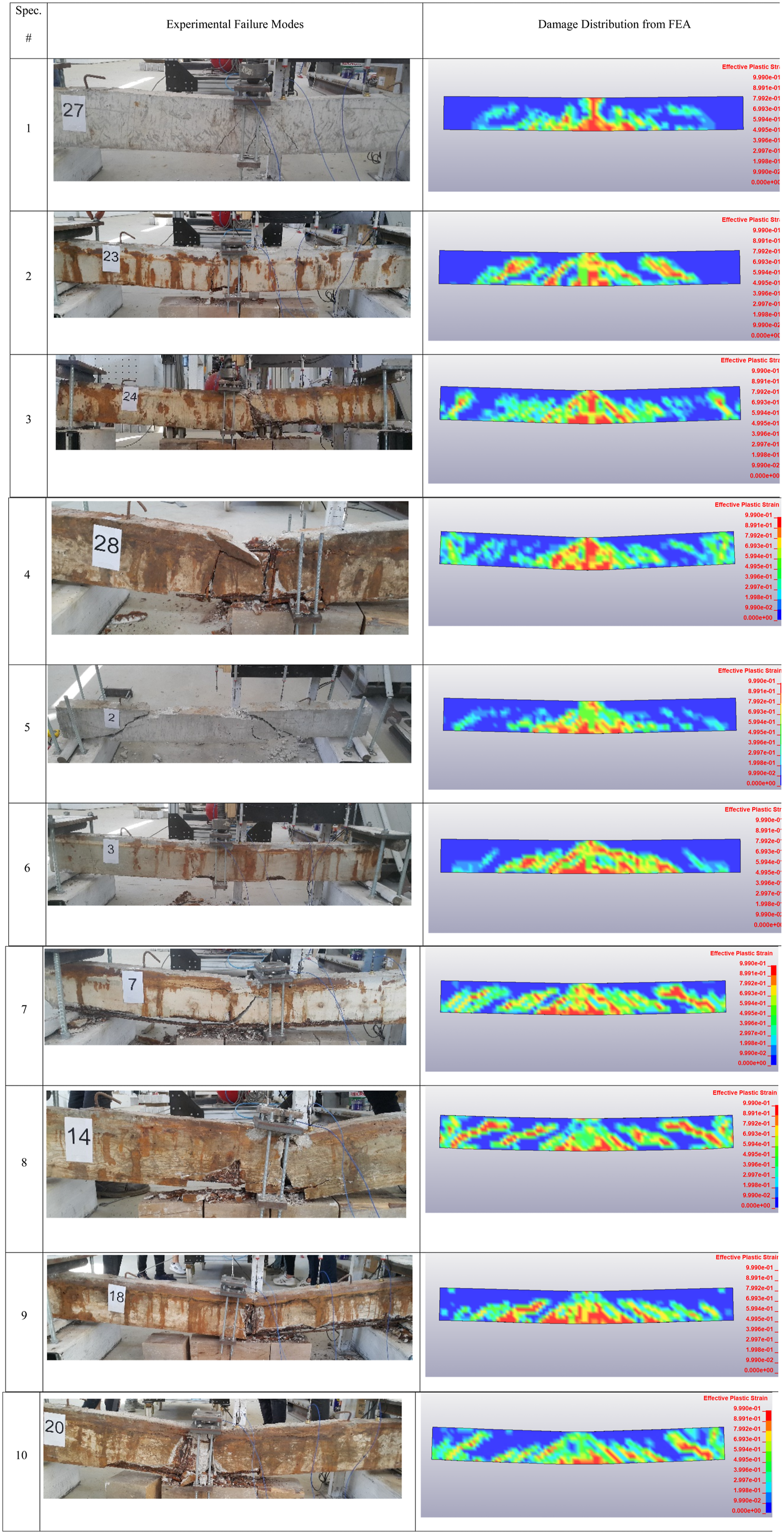
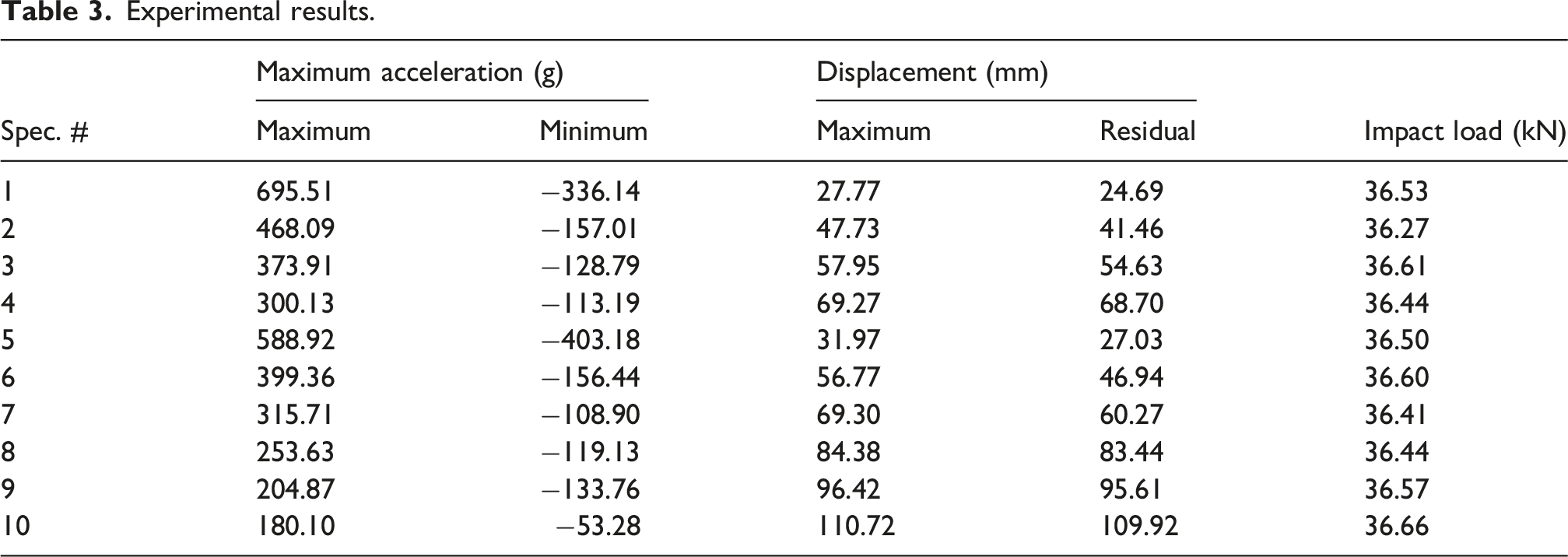
Acceleration-time, displacement-time, and maximum impact loading-time changes are measured for comments on the general behavior and performance of corroded RC beams under impact loading. In addition, the damage distributions caused by impact loading in beams, how acceleration and displacement change along the beam shear span, impact loading-displacement graphs, and energy absorption capacities are also calculated and examined. How the specimens are affected by experimental variables is also investigated. Among the three acceleration and four displacement values measured from the test elements, the maximum acceleration-time and maximum displacement-time changes closest to the midpoint of the beam where impact loading is applied are given in Figures 6 and 7, respectively. The impact loading-time graphs applied to the test elements are presented in Figure 8. The impact loading applied to corroded RC beams and the maximum displacement values at the midpoint of the beams are brought together in a graph for the same period, and impact loading-displacement graphs are drawn and given in Figure 9. The damage distributions after impact loading tests applied to corroded RC beams and those obtained from numerical analysis are given comparatively in Figure 10. The results obtained from the experiments are presented in Table 3. Table 3 presents the maximum and minimum acceleration values, maximum displacement value, and maximum value of impact loading measured from each test element. In addition, the displacement value formed as permanent plastic displacement after damping the vibration occurring in the beams due to the impact loading by reading from the maximum displacement graph for each test element is given in Table 3. The maximum displacement values are calculated by adding the absolute value of the downward and upward displacement values occurring in the beams due to impact loading. When the maximum impact load values applied to the specimens are examined, it is seen that they varied between a minimum of 36.27 kN and a maximum of 36.65 kN, and the average of the maximum impact load values is 36.50 kN. The maximum values of the impact loading applied to the test elements are measured at values very close to each other; the standard deviation value is obtained as 0.1103 kN, and the variance value is 0.0122 kN. These results showed that the free weight drop test setup, in which impact loading is applied to the test elements, can apply loads with identical impact energy levels to the RC beams by dropping the fixed weight from the same height. It has been observed that the energy losses that may occur due to friction in the free weight-dropping test setup used in the study remain at an extremely low level, and the test system can apply impact loads with identical energy levels. Maximum acceleration-time graphs of specimens. Maximum displacement-time graphs of specimens. Impact load-time graphs of specimens. Impact load-displacement graphs of specimens. Comparison of experimental failure modes of specimens and damage distributions from FEA. Experimental results.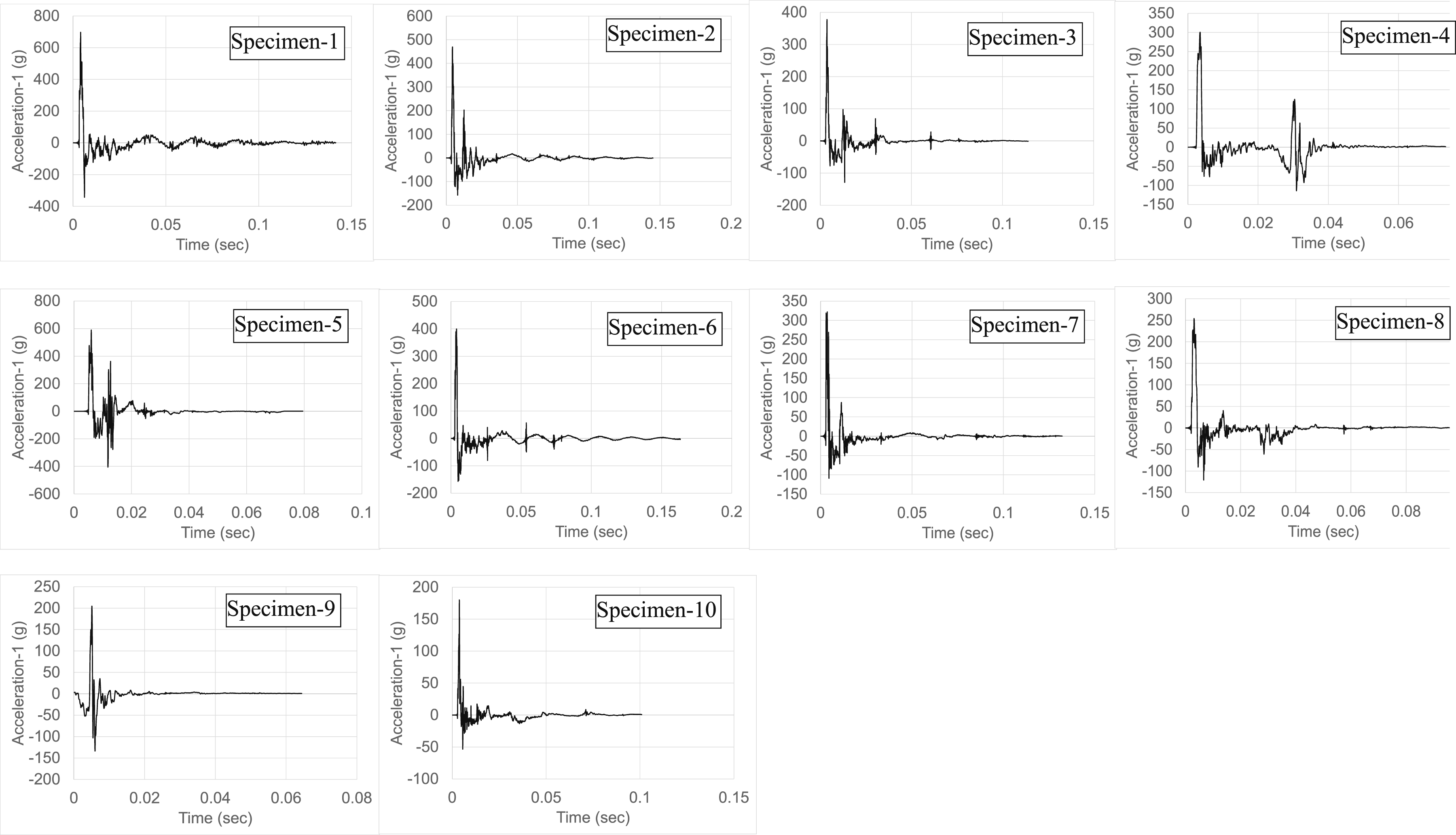
One of the variables examined within the scope of the study is that RC beams subjected to corrosion are designed to exhibit bending and shear failure as a design approach. The general behavior and performance of RC beams under impact loading have been negatively affected and decreased due to the applied corrosion effect. As a result of the corrosion applied to RC beams, the maximum acceleration values measured from the beams decreased by an average of 118% compared to the corrosion-free reference test elements, and the maximum displacement and permanent displacement values increased by an average of 142% and 167%, respectively. Corrosion of the reinforcement in the RC beams significantly reduced both the bending moment and shear force carrying capacity, rigidity, and hardness of the beams, and the decrease in these values significantly reduced the performance of the beams under the impact of impact loading. The general behavior of corroded RC beams, which are designed to exhibit shear failure, under impact loading is much more negatively affected, and their performance decreased much more than that of the specimens exhibiting bending failure. The maximum acceleration values of corroded RC beams exhibiting shear failure decreased by an average of 136% compared to the corrosion-free reference test element, and the maximum displacement and permanent displacement values increased by an average of 161% and 193%, respectively. While the maximum acceleration values of corroded RC beams exhibiting bending failure decreased by an average of 89% compared to the corrosion-free reference test element, the maximum displacement and permanent displacement values increased by 110% and 122%, respectively. The insufficiency of shear reinforcement, which also serves as confinement reinforcement in beams, led to the buckling of longitudinal reinforcements due to the displacement caused by the impact loading. Due to the decrease in the positive effect of the confinement effect on the compressive strength of concrete, the performance of RC beams under the effect of impact loading had a much more negative impact.
Another variable examined in the study is the percentage of corrosion applied to RC beams. Corrosion percentages of 10%, 15%, and 20% are applied to the test series exhibiting bending failure, and corrosion percentages of 10%, 15%, 20%, 25%, and 30% are applied to the test element series exhibiting shear failure. As the percentage of corrosion applied to RC beams increased, their performance under impact loading was negatively affected and decreased. The maximum acceleration value of the test elements exhibiting bending failure with a corrosion percentage of 10% is 25% greater than the test element with a corrosion percentage of 15%. The maximum displacement and permanent displacement values of the test element exhibiting bending failure with a 15% corrosion rate were 21% and 32% higher, respectively, than the beam with a 10% corrosion rate. The maximum acceleration value of a beam exhibiting bending failure with a corrosion percentage of 15% is 25% greater than that of a beam with a corrosion percentage of 20%. The maximum displacement and permanent displacement values of the beam exhibiting bending failure with a 20% corrosion percentage are 20% and 26% higher than the test element with a 15% corrosion percentage, respectively. The test elements exhibiting shear failure showed a very similar behavioral trend to the test elements exhibiting bending failure, and their performance under impact loading decreased with increasing corrosion percentage. The maximum acceleration value of the beam exhibiting shear failure with a 10% corrosion rate is 26% greater than the test member with a 15% corrosion rate. The maximum and permanent displacement values of the beam with shear failure with a 15% corrosion percentage are 22% and 28% higher, respectively, than the beam with a 10% corrosion percentage. The maximum acceleration value of the beam exhibiting shear failure with a 15% corrosion rate is 24% greater than the test member with a 20% corrosion rate. The maximum and permanent displacement values of the beam with shear failure with 20% corrosion percentage are 22% and 38% higher, respectively, than the beam with 15% corrosion percentage. The maximum acceleration value of the beam exhibiting shear failure with a 20% corrosion rate is 24% greater than the test member with a 25% corrosion rate. The maximum and permanent displacement values of the beam with shear failure with a 25% corrosion percentage are 14% and 15% higher, respectively, than the beam with a 20% corrosion percentage. The maximum acceleration value of the beam exhibiting shear failure with a 25% corrosion rate is 14% greater than the test member with a 30% corrosion rate. The maximum and permanent displacement values of the beam with shear failure with a 30% corrosion percentage are 15% and 15% higher, respectively, than the beam with a 25% corrosion percentage. The results showed that the increase in corrosion percentage in RC beams exhibiting both bending and shear failure showed a similarly negative trend on the performance of the beams under the impact loading effect. While each 5% decrease in the corrosion percentage in RC beams caused the maximum acceleration values to increase by an average of 23%, a 5% increase in the corrosion percentage caused an average increase of 19% and 26% in the maximum and permanent displacement values, respectively.


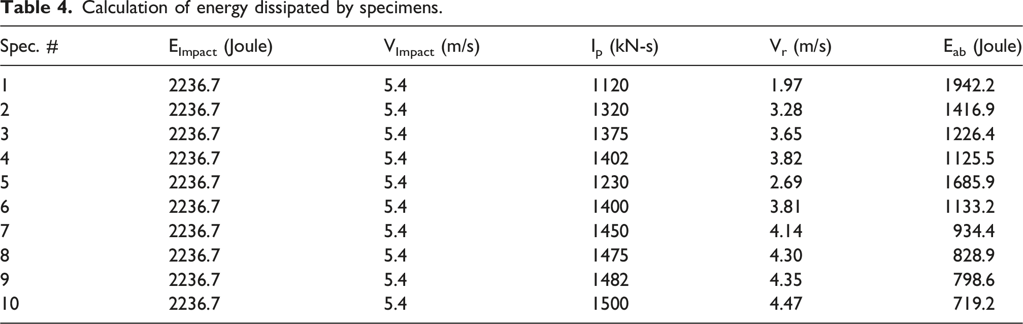
Calculation of energy dissipated by specimens.
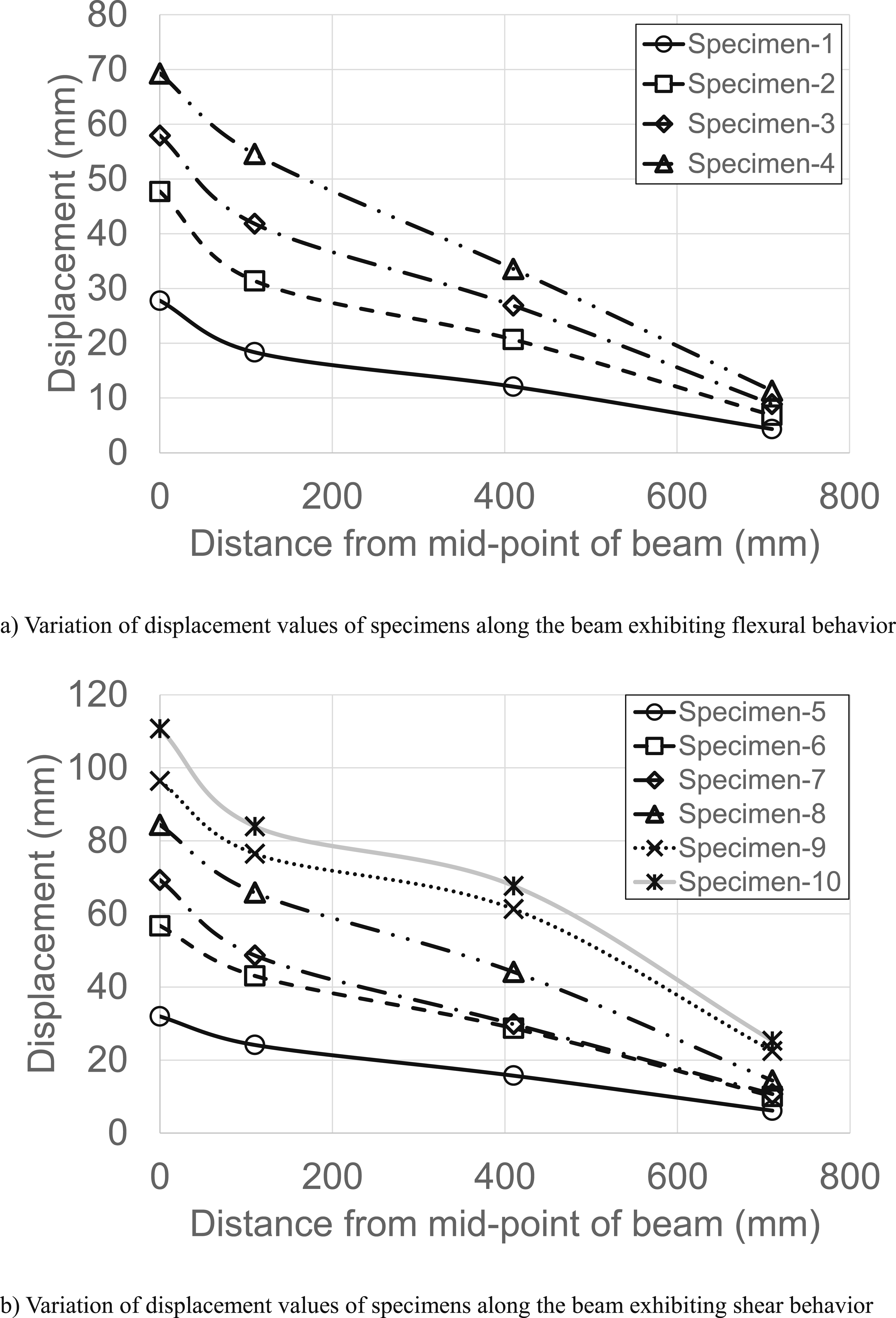
It is aimed to examine how acceleration and displacement values change between the beam midpoint where impact loading is applied and the beam support by taking three acceleration and four displacement measurements on corroded RC specimens. How the maximum acceleration values obtained between the beam midpoint and supports of the test elements change as they move away from the beam midpoint is shown in the graphs in Figure 11, and the change in the maximum displacement values is presented in Figure 12. Figure 11 presents the changes in the measured maximum acceleration values between the beam support and its midpoint separately for the test elements exhibiting bending and shear failure. It is observed that the acceleration values measured along the beam shear span, which are among the specimens exhibiting both bending failure and shear failure, decreased from the midpoint of the beam to the support, showing a behavior trend that could be considered linear. It is seen that the slope of the lines showing the behavior trend of the maximum acceleration values showing a decreasing trend towards the beam support in the test elements exhibiting shear failure is higher than in the experimental elements exhibiting bending failure. In RC beams exhibiting shear failure, the acceleration spread from the middle point of the beam towards the support due to impact loading decreased more rapidly, and the acceleration wave occurring in the beams was damped more quickly, decreased, and moved towards the support. When the maximum displacement values of the specimens presented in Figure 12 are examined, it is seen that there is a rapid decrease in maximum displacement for beams exhibiting both bending failure and shear failure from the beam midpoint to the second measurement point. However, in the beams exhibiting shear failure, the decrease rate between the first two measurement points in the maximum displacement values is higher than in the beams exhibiting bending failure. In RC beams exhibiting shear failure, the displacement propagation occurring due to impact loading is damped much faster. This behavior trend is observed more clearly, especially in RC beams with higher corrosion percentages. In beams with 25% and 30% corrosion rates and exhibiting shear failure, the decrease and damping in the maximum displacement values along the shear span are seen more clearly. Corrosion applied to RC beams has also significantly affected the collapse mechanisms and damage distributions under impact loading and has an extremely negative effect on them. When the photographs given in Figure 10 are examined, it is seen that the application of corrosion in the RC beams of both series, which are designed to exhibit bending and shear failure separately, negatively affects the magnitude and distribution of the damage. As the percentage of corrosion applied to RC beams increased, the amount of damage to RC beams exhibiting bending and shear failure increased, crack widths increased significantly, and the resulting collapse mechanism became much more destructive. When the damage distributions of RC beams exhibiting shear and bending failure are compared, it is seen that the damage occurring in beams designed to exhibit shear failure is much greater, and the fractures occurring in the concrete and the spalling in the concrete cover are distributed to much larger areas. In the specimens designed to exhibit shear failure, due to the lack of the confinement effect created by the shear reinforcement around the longitudinal reinforcements on the concrete, spalling occurred in much larger areas in the concrete cover area located at the bottom of the longitudinal reinforcements, and the widths of the cracks are much larger. Crushing and fractures in the concrete have also spread to a wider area. It is observed that ruptures in the longitudinal and shear reinforcements also occurred in the test elements exhibiting shear failure, where 30%, 25%, and 20% corrosion percentages are applied. Variation of accelerations measured from specimens with distance. Variation of displacements measured from specimens with distance.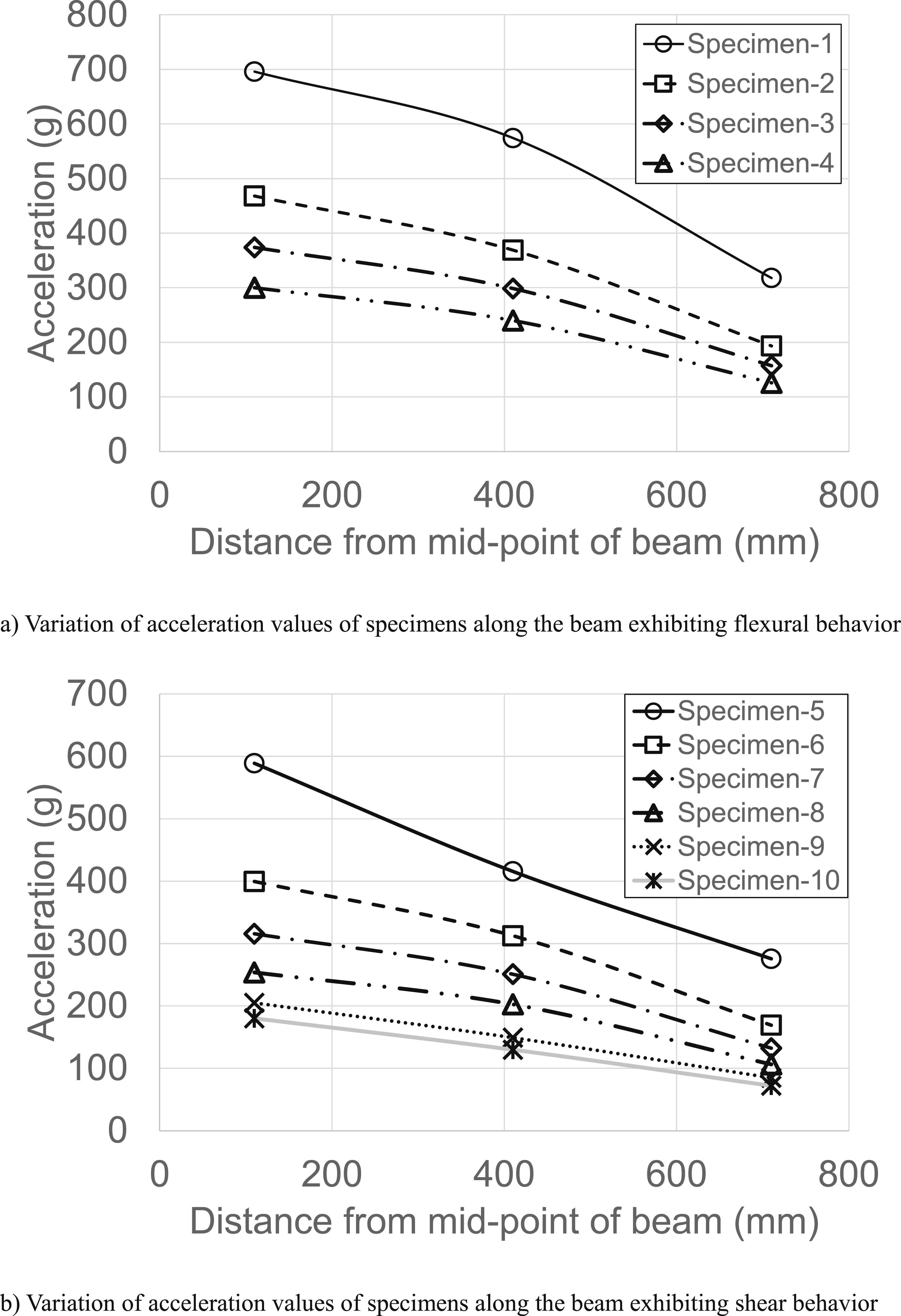
Numerical study
LS-DYNA software has been utilized for generation the finite element model (FEM) of the corroded RC beams subjected to impact loading (LS-DYNA, 2007). The LS-DYNA software, which can perform nonlinear dynamic analysis, includes many concrete material models for dynamic loading and allows for application of advanced contact algorithms for simulating the interaction of collided parts during impact analysis (Şengel et al., 2022a, 2022b).
The generated FEM composes of the RC beam, corroded steel rebar, loading plate, support and hammer parts. While an 8-node hexahedron solid element was used for modeling the RC beam, loading plate, support, and hammer, the steel rebars were modeled with a Hughes-Liu beam element (Şengel et al., 2022a, 2022b). The finite element model of Specimen 1 is given in Figure 13 as an example. After mesh convergence trials, it has been found that the element sizes of rebars, concrete, loading plate, supports, and hammer, taken as 25, 20, 20, 5, and 5 mm, respectively, provide optimum results considering accurate responses and computational time. Impact load was applied by defining the velocity of the hammer at the moment of collision. The friction occurring in the drop of steel weight was neglected. Finite element model of Specimen-1.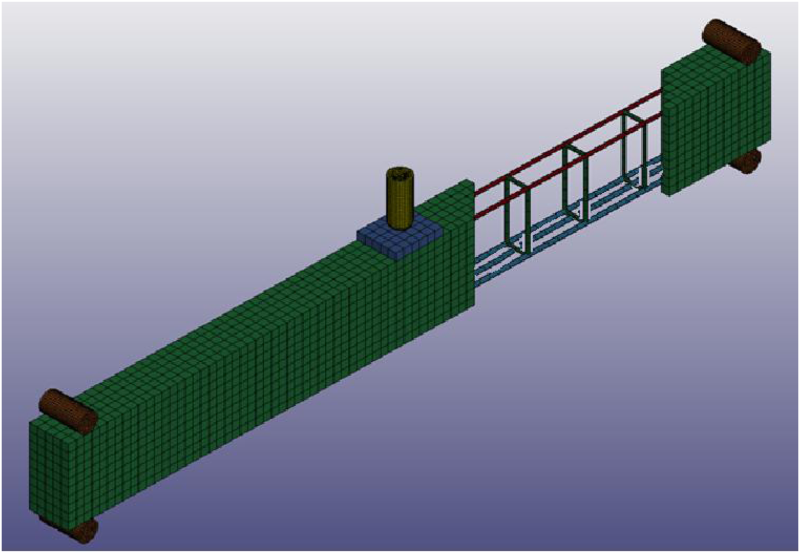
The concrete material was modeled utilizing the 159- CSCM concrete (Continuous Surface Cap Model) material model, which is based on isotropic constitutive equations and includes a continuous yield surface formulated in terms of three stress invariants of the deviatoric stress tensor. The yield surface can be considered ductile and brittle damage, utilizing a damage parameter ranging from zero (undamaged) to one (fully damaged) (Xiao et al., 2017b). The model allows element erosion once the damage parameter reaches one; the damaged concrete is removed from the solution, and computational overflow is prevented. Detailed properties of the CSCM model are presented in its user’s manual (Murray, 2007). The CSCM model requires only three parameters to model concrete material: the unconfined compressive strength, maximum aggregate size, and density. The maximum aggregate size and concrete density were defined as 20 mm and 2400 kg/m3, respectively. In LS-DYNA, the CSC model mainly includes the failure surface, damage functions, and strain rate formulations. The failure surface is combined with the shear failure surface and cap hardening surface, in which these two surfaces are continuously and smoothly connected, as presented in Figure 14(a). The failure surface is characterized by three stress tensor invariants (J1, J2, and J3) and the cap hardening parameter κ. The shear surface consists of a triaxial compression (TXC) surface, a triaxial extension (TXE) surface, and a triaxial torsion (TOR) surface. Figure 14(b) and (c) present the triaxial compression and tension meridians, respectively. Detailed information about the CSCM concrete model, whose stress-strain graphs are given in Figure 14, is given. The CSCM model, suitable for concrete with a compressive strength between 28 MPa and 58 MPa, was also utilized for modeling concrete since the CSCM model best captured dynamic responses and failure modes in the experimental results compared to other models like *MAT_WINFRITH_CONCRETE (MAT_084-085) and MAT_CONCRETE_DAMAGE_REL3 (MAT_072R3) in the preliminary analysis carried out. Besides, the fact that the CSCM material model successfully models the dynamic response and failure behavior of the concrete material has been reported in previous studies. Cscm concrete model stress-strain relationships.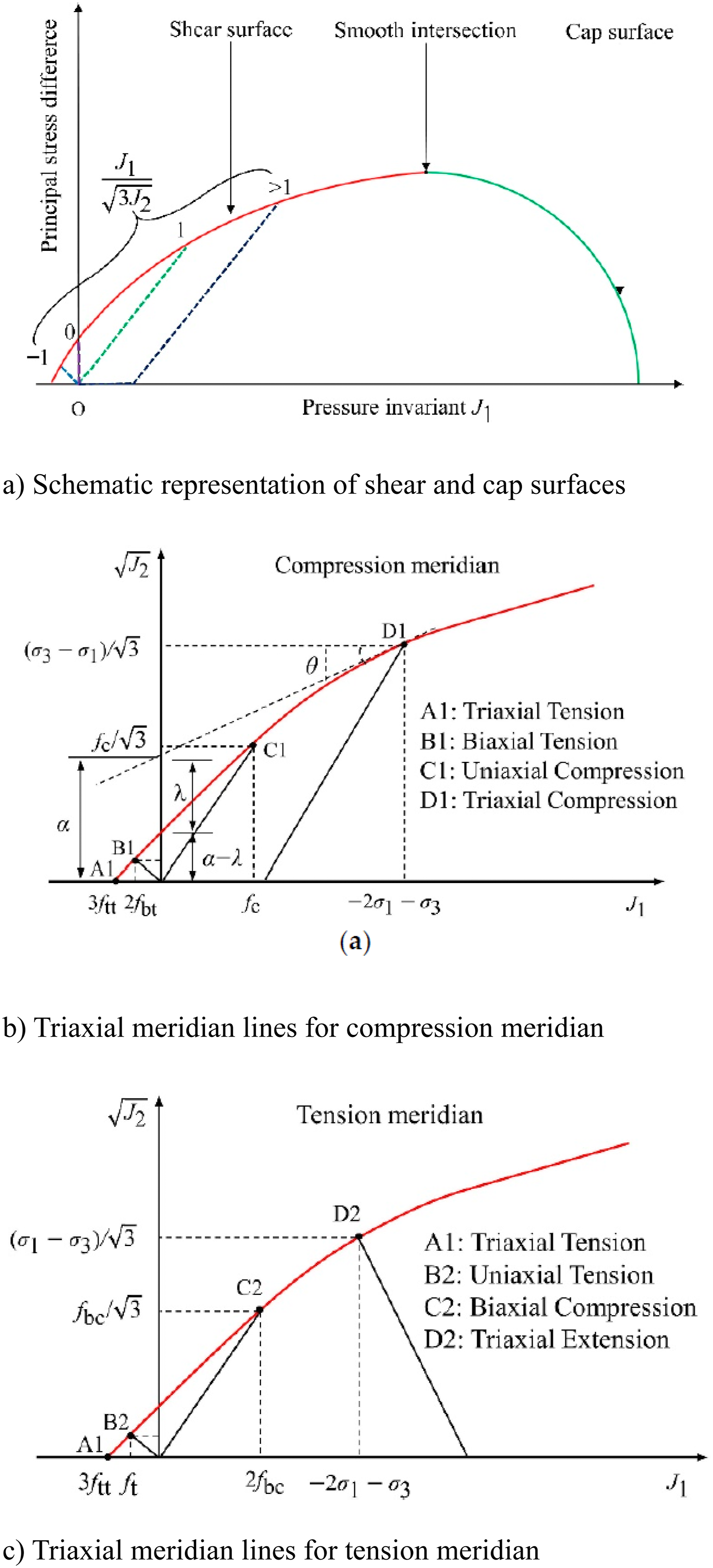
The longitudinal rebars and stirrups were modeled as elastic-plastic material without hardening. The steel yield strengths and elastic modulus of longitudinal bars and shear reinforcements were defined as 433 MPa, 202 GPa, and 427 MPa, 201 GPa, respectively. Poisson’s ratio and the density were taken as 0.3 and 7850 kg/m3 for whole rebars. While the loading plate was modeled as an elastic material by defining the elastic Modulus and Poisson’s ratio as 200,000 MPa and 0.3, respectively, the hammer and supports were rigid assumptions.
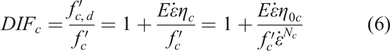
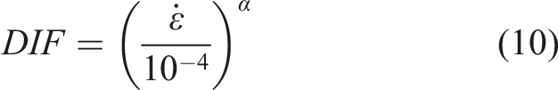
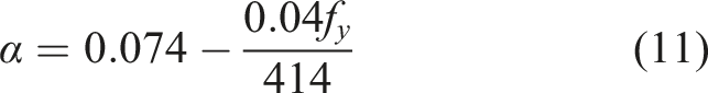
Impulsive loading enhances steel and concrete materials’ tensile and compressive strength. This phenomenon is known as a strain-rate effect; its consideration in impact analysis is compulsory for properly evaluating dynamic responses (Şengel et al., 2022a, 2022b). This effect is commonly implemented in the material model using a Dynamic Increase Factor (DIF), which refers to a ratio of dynamic strength to static strength. Several equations were presented to define DIFs of steel and concrete materials in the literature (Fan et al., 2011; Hao and Hao, 2014; Malvar, 1998; Malvar and Crawford, 1998; Malvar and Ross, 1998). For the CSCM model, tensile (DIF
t
) and compression (DIF
c
) dynamic increase factors can be expressed as follows (Guo et al., 2018):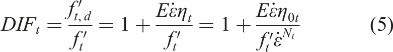
η
t
, η
c
, and η
s
, which are the fluidity parameters in uniaxial tensile stress, shear stress, and uniaxial compressive stress, can be defined as follows: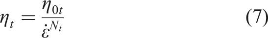
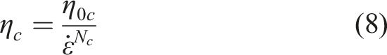

Translation DOFs of the steel support were constrained, while rotation DOFs were free using the ∗BOUNDARY_SPC_SET keyword. The interface nodes of the RC beam and the loading plate were merged to get a fully bonded contact behavior. These two parts are fixed together in the test by anchored studs. The penalty-based contact algorithm was used to interface the hammer and the loading plate.
The corrosion-induced deteriorations on RC beams were implemented in present FEM by empirical equations, i.e., the degradation of effective cross-sectional area and yield strength of reinforcements, concrete strength, and the rebar-concrete bond-slip relationship (Lindvall, 2000; Wu et al., 2024). In the FEM, it was assumed that the reinforcements subjected to uniform corrosion, and the effective cross-sectional are and yield strength which can be calculated by equations (12) and (13), respectively (Du et al., 2005; Wu et al., 2024):

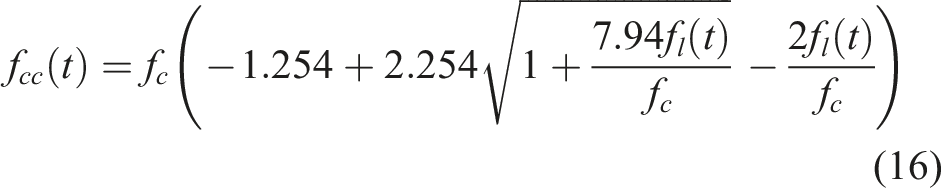
Due to the volumetric expansion of corrosion products formed during the accelerated corrosion process, additional tensile stresses were introduced, leading to a considerable reduction in the strength of the concrete. The residual compressive strength of the corroded concrete cover can be calculated using equations (14) and (15) (Coronelli and Gambarova, 2004; Wu et al., 2024) while the compressive strength of the confined concrete, denoted as f
cc
(t), is obtained through equation (16) (Mander et al., 1988).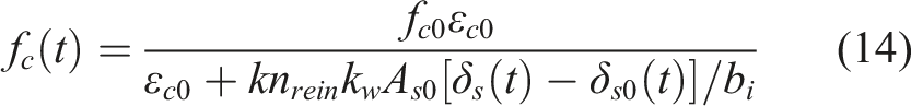


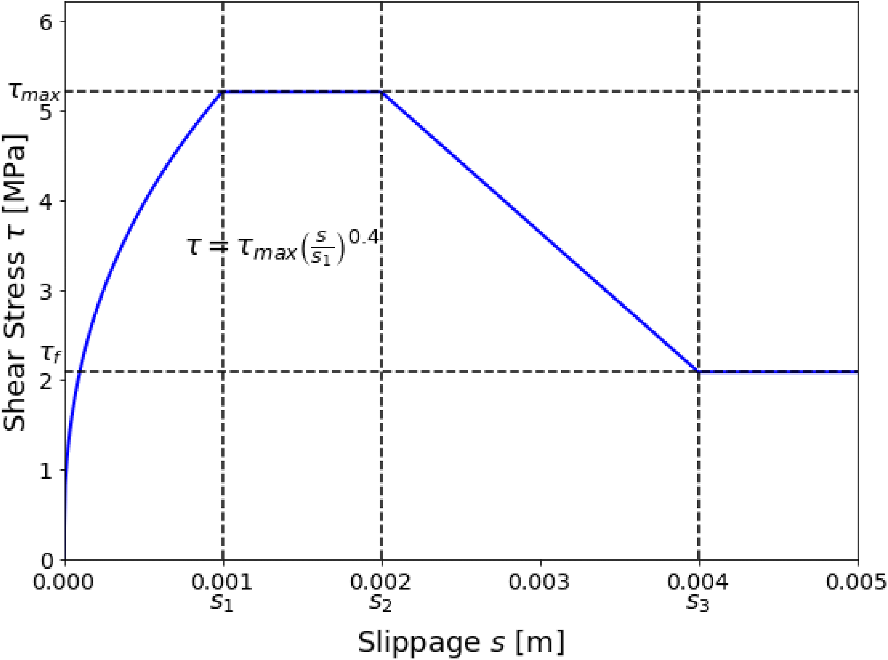
The rebar-concrete bond-slip relationship degrades because of the volume expansion of corrosion products during the accelerated corrosion process. The rebar-concrete bond-slip relationship, which is depicted in Figure 15, has been defined utilizing *CONSTRAINED_BEAM_IN_SOLID existing in the LS-DYNA. In the Figure 13, τ
max
and τ
f
are the maximum and residual shear stress at the rebar-concrete interface, respectively. The relative slippage between reinforcements and concrete s was calculated based on the τ
max
given in equation (18) considering corrosion degree (Lee et al., 2002): Rebar-concrete bond-slip relationship.
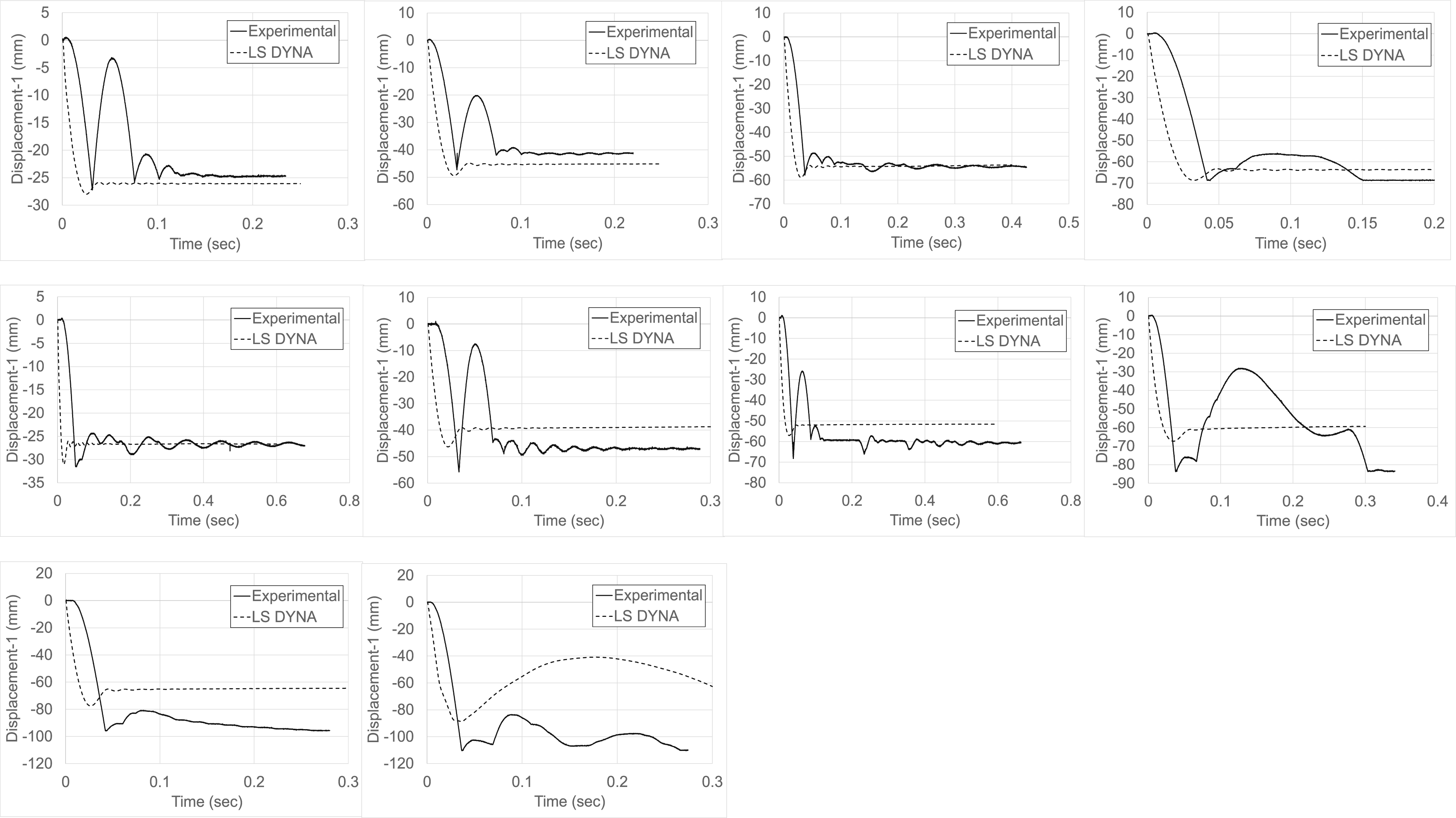
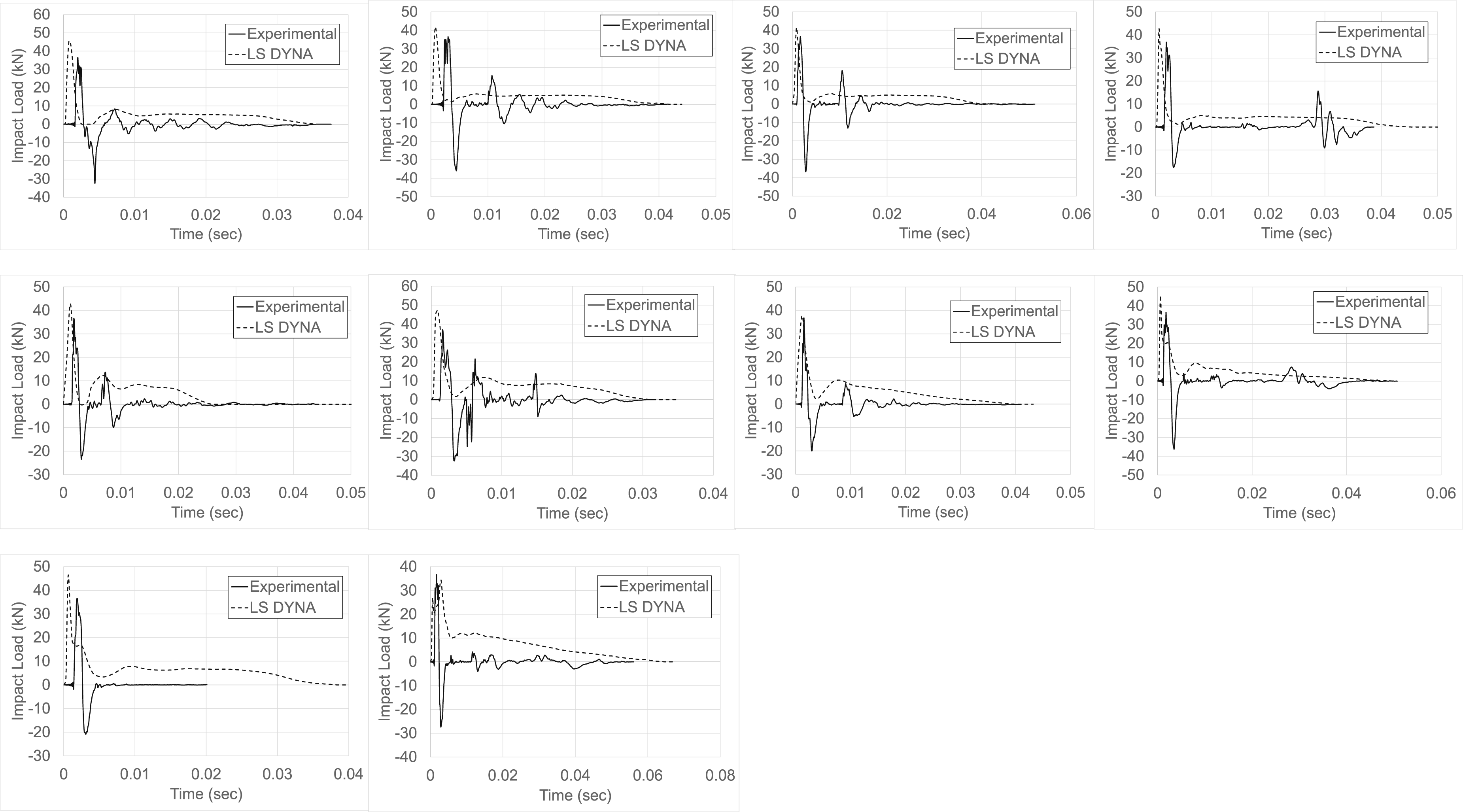
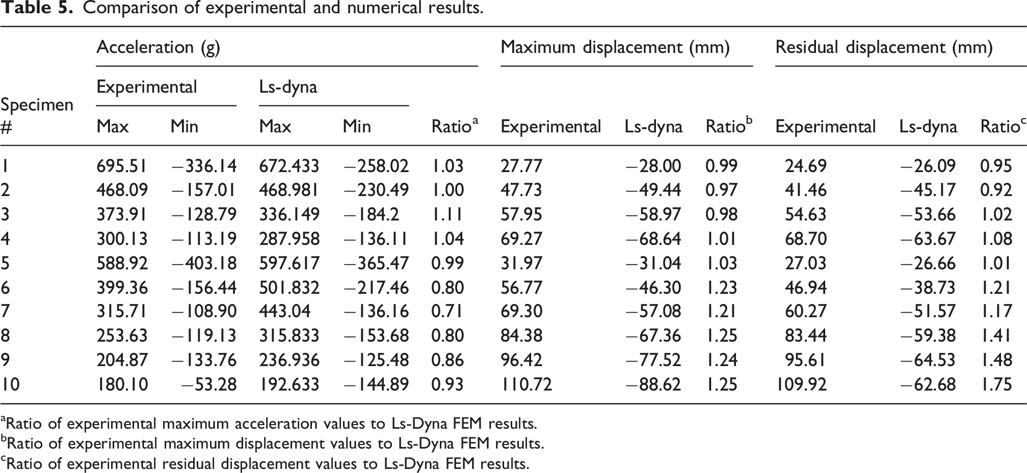
Dynamic responses of acceleration, displacement, and impact loads obtained by finite element analysis have been depicted in Figure 16, Figure 17, and Figure 18, compared with test results. The comparison of experimental and finite element analysis results is presented in Table 5. Besides, Figure 10 depicts the damage distributions obtained from numerical analysis. When the results given in Table 5 are examined, it is seen that the numerical analysis results of the series exhibiting flexural failure among the corroded RC beams with two different failure modes tested within the scope of the study are quite successful and a behavior that is significantly compatible with the experimental results is obtained. The average values of the ratios of the experimental maximum acceleration, maximum displacement and residual displacement values of the corroded RC beams designed to fail by exhibiting flexural failure, where the shear reinforcement is placed at a sufficient rate, to the results obtained as a result of the numerical analysis were calculated as 1.05, 0.99 and 0.99, respectively, and the results are in great agreement with the experimental values. The numerical analysis results obtained in the series of corroded RC beams designed to exhibit shear failure and insufficient shear strength, could not exhibit results as successful as the corroded beam specimens designed to exhibit flexural failure. The average ratios of the experimental maximum acceleration, maximum displacement and residual displacement values of the corroded beam specimens exhibiting shear failure to the values obtained from the numerical analysis were calculated as 0.85, 1.20 and 1.34, respectively. It was observed that the experimental maximum acceleration values of the RC beams with insufficient shear reinforcement exhibited lower values than the numerical values, while the experimental maximum and residual displacement values had greater values than the numerical values. These obtained results showed that the numerical analysis model exhibited a more rigid behavior compared to the experimental specimens, and due to its greater hardness and rigidity, the accelerations were calculated larger and the displacement values were calculated lower. In corroded RC beams with insufficient shear reinforcement, the insufficient confinement effect created by shear reinforcement in longitudinal reinforcements, the increase in the risk of buckling in longitudinal reinforcements due to the lack of positive effect created by confinement in longitudinal reinforcements and the increase in spalling and pitting in the concrete shell as a result of buckling in longitudinal reinforcements, the confinement effect created by shear reinforcements not having a positive effect on the compressive strength due to the behavior principles of the concrete under the effect of 3-axis stress, can be counted as the problems observed in RC beams with insufficient shear strength. It is thought that the problems that occur in RC beams with insufficient shear strength and corrosion, which are briefly summarized above, cannot be completely transferred to the numerical analysis model and the differences between the experimental results and the numerical analysis results are caused. Despite a comprehensive review in the literature, a suitable concrete material model and strain rate effect function could not be found for modeling RC beams with insufficient shear reinforcement, lacking the confinement effect provided by the shear reinforcement and the ability to reduce the buckling risk in longitudinal reinforcements. Although the 159-CSCM concrete material model used in the numerical analyses of the study is the most preferred and used material model in the current literature on this subject, it is not thought that the effects of shear reinforcement on the material behavior of concrete are fully taken into account in this model. It can be seen from the analysis results of the first experimental specimen series that exhibited flexural failure that the negative effects of corrosion on the material behavior of concrete can be successfully transferred to the numerical analysis model to a significant extent. However, it has been concluded that the inadequacy of shear reinforcement is effective together with corrosion, and the main reason for not achieving the same success in the experimental specimens where shear failure occurs is that the effects of inadequate shear strength and inadequate confinement effect of shear reinforcement on the concrete material behavior in numerical analysis cannot be fully taken into account. Comparison of maximum acceleration-time graphs from experiment and FEA. Comparison of maximum displacement-time graphs from experiment and FEA. Comparison of impact load-time graphs from experiment and FEA. Comparison of experimental and numerical results. aRatio of experimental maximum acceleration values to Ls-Dyna FEM results. bRatio of experimental maximum displacement values to Ls-Dyna FEM results. cRatio of experimental residual displacement values to Ls-Dyna FEM results.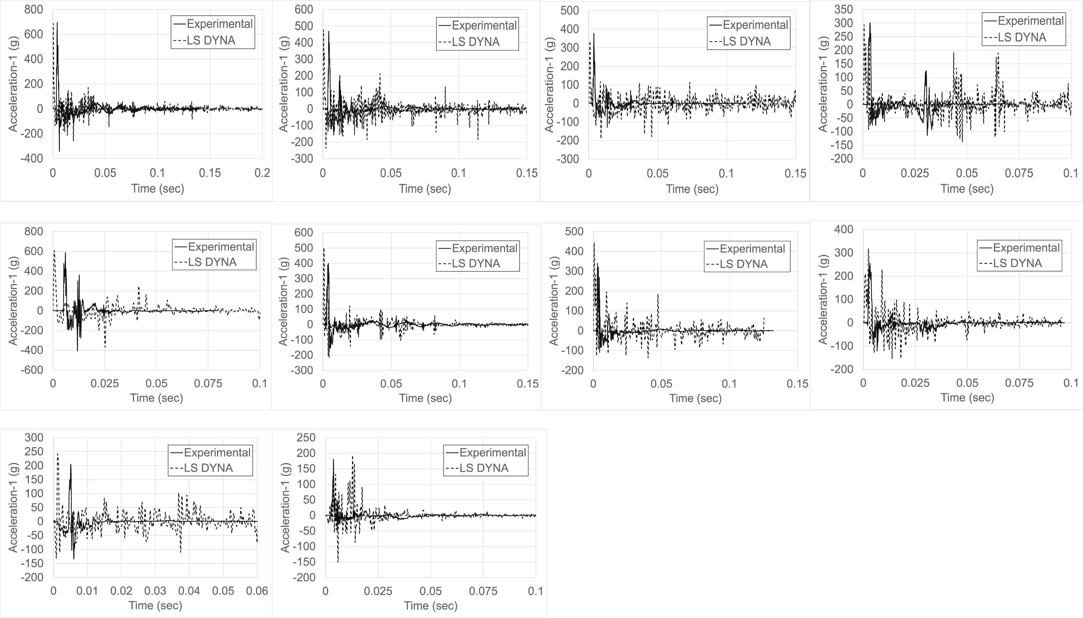
Conclusions
Corrosion is one of the most common problems in RC structures due to environmental effects, which negatively affects important structural parameters such as load-displacement behavior, carrying capacity, rigidity, and energy consumption capacity of RC beams under the influence of static, quasi-static, and cyclic loading. When the literature is examined, it can be seen that many studies examine the behavior of corroded RC structural elements and beams under the influence of static, quasi-static, and cyclic loading and investigate the problems caused by corrosion on their strength and general performance. However, after a comprehensive literature review, it is seen that there are a limited number of studies examining the behavior of RC beams subjected to corrosion under the influence of sudden dynamic impact loading and that there is no comprehensive research on this subject. Corroded RC beams may be subjected to impact loading for different reasons, such as vehicles hitting highway and sea bridges, hitting objects brought by water, hitting soil or rocks due to landslides, and hitting air shock waves resulting from explosions. For this reason, an experimental study is planned to examine the behavior and performance of corroded RC beams under impact loading. The study examines the percentage of corrosion applied to RC beams and the design of the beams to exhibit shear and bending failure as experimental variables. Impact loading is applied to the beams using a free weight-dropping test setup designed by the authors. The beams’ acceleration-time, displacement-time, and impact loading-time distributions were measured, and the effects of the experimental variables on the behavior were interpreted. • It has been determined that the performance and general behavior of RC beams under impact loading due to corrosion are negatively affected, maximum acceleration values decrease, and maximum and permanent displacement values increase significantly. The maximum acceleration values of the corrosion-free reference test elements were, on average, 118% greater than the corroded beams, and the maximum and permanent displacement values of the corroded reinforced concrete beams were, on average, 89% and 136% greater than the corrosion-free reference beams. • Insufficient shear reinforcement design of RC beams to exhibit shear failure, combined with the effect of corrosion, has negatively affected and reduced the overall behavior and performance level under impact loading much more. The maximum acceleration values of corroded RC beams designed to exhibit flexural failure were, on average, 18% greater than the test elements exhibiting shear failure, and the maximum and permanent displacement values of the beams exhibiting shear failure were 20% and 15% greater, respectively than the test elements exhibiting flexural failure. • As the corrosion percentage of RC beams increased, their performance under impact loading was significantly negatively affected; maximum acceleration values decreased, and maximum and permanent displacement values increased significantly. As the corrosion percentage of corroded reinforced concrete beams increased by 5%, the maximum displacement and permanent displacement values increased by an average of 19% and 26%, respectively, and as the corrosion percentage decreased by every 5%, the maximum acceleration values increased by an average of 23%. • Numerical analyses of corroded RC beams exhibiting two different failure modes included in the experimental program were performed using the Ls-dyna software. It was observed that the numerical analysis results of corroded RC beams exhibiting flexural failure were highly compatible and successful with the experimental results. However, the numerical analysis results of corroded RC beams exhibiting shear failure with insufficient shear reinforcement were not as compatible and successful as the experimental results. • The corrosion-induced deteriorations on RC beams were implemented in present FEM by empirical equations, i.e., the degradation of effective cross-sectional area and yield strength of reinforcements, concrete strength, and the rebar-concrete bond-slip relationship. It is thought that this integrated holistic approach implemented in the Ls-Dyna software, which includes all the effects of corrosion occurring in the reinforcement, is effective in obtaining successful numerical analysis results that are compatible with the experimental results. • It is thought that the main reasons for obtaining less successful numerical analysis results in corroded RC beams exhibiting shear failure due to insufficient shear reinforcement are the failure to fully consider the negative effects of insufficient shear reinforcement on the material model of the concrete and the difference in the strain-rate effect functions of beams with insufficient shear resistance.
Footnotes
Funding
The authors received no financial support for the research, authorship, and/or publication of this article.
Declaration of conflicting interests
The authors declared no potential conflicts of interest with respect to the research, authorship, and/or publication of this article.