
Abstract
This paper presents regression-based backbone models for lumped-plasticity nonlinear hinges representing H-shaped beams, H-shaped braces, and HSS columns in steel moment-resisting and concentrically braced frames. The formulations are calibrated against 66 published cyclic tests and expressed in normalized form for direct implementation as user-defined hinges in commercial analysis software. Connection-specific beam hinges are developed for welded flange–bolted web (WFBW), reduced beam sections (RBSs) and cover-plated connections (CPCs) details, while brace and column hinges explicitly account for asymmetric inelastic behavior and axial load effects, respectively. Validation against experimental envelopes and existing code-oriented hinge models demonstrates improved prediction of strength and deformation capacities, particularly for modern high-strength steels. System-level application to a 15-story steel building is demonstrated through pushover analysis of the moment-resisting frame configuration and nonlinear response history analysis of the concentrically braced frame configuration. The results reveal that the proposed connection-specific hinges accurately predict a strong-column-weak-beam failure mechanism, whereas generalized code models overestimate beam ductility and misidentify failure modes. The dynamic analysis further illustrates the framework’s applicability to braced systems. These findings demonstrate that accurate component-level hinge modeling is essential for credible performance-based seismic assessment in ASCE 41-23 compliant evaluations.
Keywords
Introduction
Steel moment-resisting frames (MRFs) and concentrically braced frames (CBFs) are among the most widely adopted structural systems in seismic regions due to their ductility, energy dissipation capacity, and adaptability to diverse architectural layouts. Their seismic effectiveness, however, relies critically on accurately predicting nonlinear behavior under strong ground motions. Historical earthquakes, including the 1994 Northridge event in the United States, the 1995 Kobe earthquake in Japan, and the 1999 Chi-Chi earthquake in Taiwan, revealed vulnerabilities in steel systems, such as local and global buckling, brittle brace fracture, and premature connection failures (Miller, 1998; Tsai et al., 2000; Youssef et al., 1995). These observations underscore the need for advanced performance-based seismic design (PBSD) methodologies capable of reliably capturing structural inelasticity.
To facilitate PBSD, standards such as ATC-40 (Applied Technology Council, 1996) , FEMA 273 (BSSC, 1997), ASCE (2023), AISC (2022a), and TEASPA-V5.0 (Lin et al., 2025) as well as preliminary screening methodologies for existing high-rise steel structures (Lin et al., 2026b) outline procedures for seismic evaluation and retrofit, commonly employing nonlinear static pushover analysis (NSPA) and nonlinear response history analysis (NRHA) to assess global and local performance. The accuracy and practical utility of these analyses hinge directly on the component models used to idealize beams, columns, and braces.
Distributed plasticity (fiber) models provide detailed sectional behavior and can represent the spread of inelasticity along a member’s length (Prakash and Srivastava, 2019), but they incur significantly higher computational costs, making them less practical for large-scale building analyses (Pantoja et al., 2025). In contrast, for system-level analysis where balancing computational efficiency with accuracy is paramount (Hou et al., 2023), the lumped plasticity approach is favored. In commercial software platforms such as ETABS and SAP2000, which are central to routine engineering practice, behavior is most commonly modeled using lumped-plasticity hinges. These hinges are defined by a backbone (monotonic) curve and a built-in cyclic rule, with parameters typically adopted from generalized code tables. The computational efficiency of this approach is well established, with studies noting it can reduce analysis time by nearly 50% compared to more complex models for certain applications (Lee et al., 2021). Consequently, the reliability of the entire assessment depends critically on the fidelity of these simplified backbone formulations. This reliance on accurate component modeling is equally critical for emerging resilient structural schemes, such as mega-frame with sub-structure isolation, where hierarchical energy dissipation and inertial tuning must be precisely captured (Xu et al., 2026a).
The paradigm of structural safety is shifting toward resilience rather than resistance, adaptability rather than rigidity, and sustainability rather than overdesign, guiding the development of experimentally calibrated component models for performance-based seismic design (Xu et al., 2026b). Code-oriented hinge backbones are necessarily generalized and may not accurately represent the behavior of modern high-strength steels (e.g., SM570, SN490 B, Q460 C) or contemporary connection types such as pre-Northridge welded flange–bolted web (WFBW), reduced beam sections (RBSs) and cover-plated connections (CPCs) details. Recent experimental and numerical investigations on high-strength steel H-section columns have demonstrated that flange width-to-thickness ratios significantly influence cyclic performance, with seismic-grade HSS exhibiting favorable hysteretic behavior and enhanced ductility compared to conventional grades (Han et al., 2025). In a related development, regression-based hinge modeling frameworks have recently been extended to concrete-filled steel tubular (CFST) columns, confirming their applicability beyond bare steel sections and highlighting the need for composite-specific hinge models in design standards (Lin et al., 2026). These materials and detailing practices are underrepresented in the legacy datasets underlying provisions such as AISC 342-22. Experimental evidence and PBSD guidance indicate that predicted collapse capacities and other performance metrics can be sensitive to assumptions regarding nonlinear component backbones and deterioration models (Cravero et al., 2020; Lignos et al., 2019; NIST, 2010), highlighting that recommended parameters in current standards represent calibrated best estimates rather than universally applicable rules. These observations motivate the development of experimentally grounded, component-specific hinge formulations tailored to modern materials and connection details, while remaining compatible with the simplified hinge formats used in mainstream software such as ETABS and SAP2000.
This study addresses this gap by developing a suite of regression-based nonlinear hinge models for three critical components in steel MRFs and CBFs: H-shaped beams (including WFBW, RBS, and CPC connections), H-shaped braces, and HSS columns. The models are calibrated against a curated database of 66 cyclic tests, encompassing conventional and high-strength steels (Chen, 1991, 2019, 2020a, 2020b; Chou and Wu, 2017; Chung et al., 2005; Hashimoto et al., 2011; Hsueh, 2016; Huang, 2019; Lee, 2006; Lin, 2010; Lin et al., 2013; Ou, 2010; Popov and Stephen, 1972; Tang, 2013; Tsai, 2010; Tsai and Popov, 1988; Uenoya et al., 2002; Wang et al., 2014; Wu, 2005; Yang, 2016). Normalized backbone curves are derived through least-squares regression, explicitly incorporating parameters such as flange and web slenderness, expected yield strength, and axial load ratio, that govern strength and deformation capacity. The resulting hinge formulations are designed for direct implementation as user-defined hinges in commercial software, ensuring practical applicability in routine performance-based assessment workflows. To illustrate the practical implications of the proposed hinge models at the structural level, a 15-story steel building is analyzed under two lateral system configurations. A pushover analysis of the MRF compares the code-based backbone with the proposed connection-specific models and explores how backbone definitions affect global response, drift distributions, and predicted plastic mechanisms. A NRHA of the CBF configuration demonstrates the proposed brace hinge model under dynamic loading.
The remainder of this paper is organized as follows. The next section presents the development of the nonlinear hinge models, including the experimental database, calibration framework, and hysteretic rule selection. Their component-level performance is then validated against experimental data and existing code provisions, followed by a system-level application through a 15-story building case study. The paper finishes with the conclusions of the study.
Development of nonlinear hinge models
This section presents the development of experimentally calibrated nonlinear hinge models for three steel frame components: H-shaped beams, H-shaped braces, and HSS columns. The methodology proceeds in three stages. First, a curated database of 66 cyclic tests is compiled and analyzed statistically to establish the calibration framework. Second, backbone curves are calibrated through regression analysis. Third, hysteretic rules are defined for practical implementation.
Experimental database and calibration framework
Summary of material strengths.
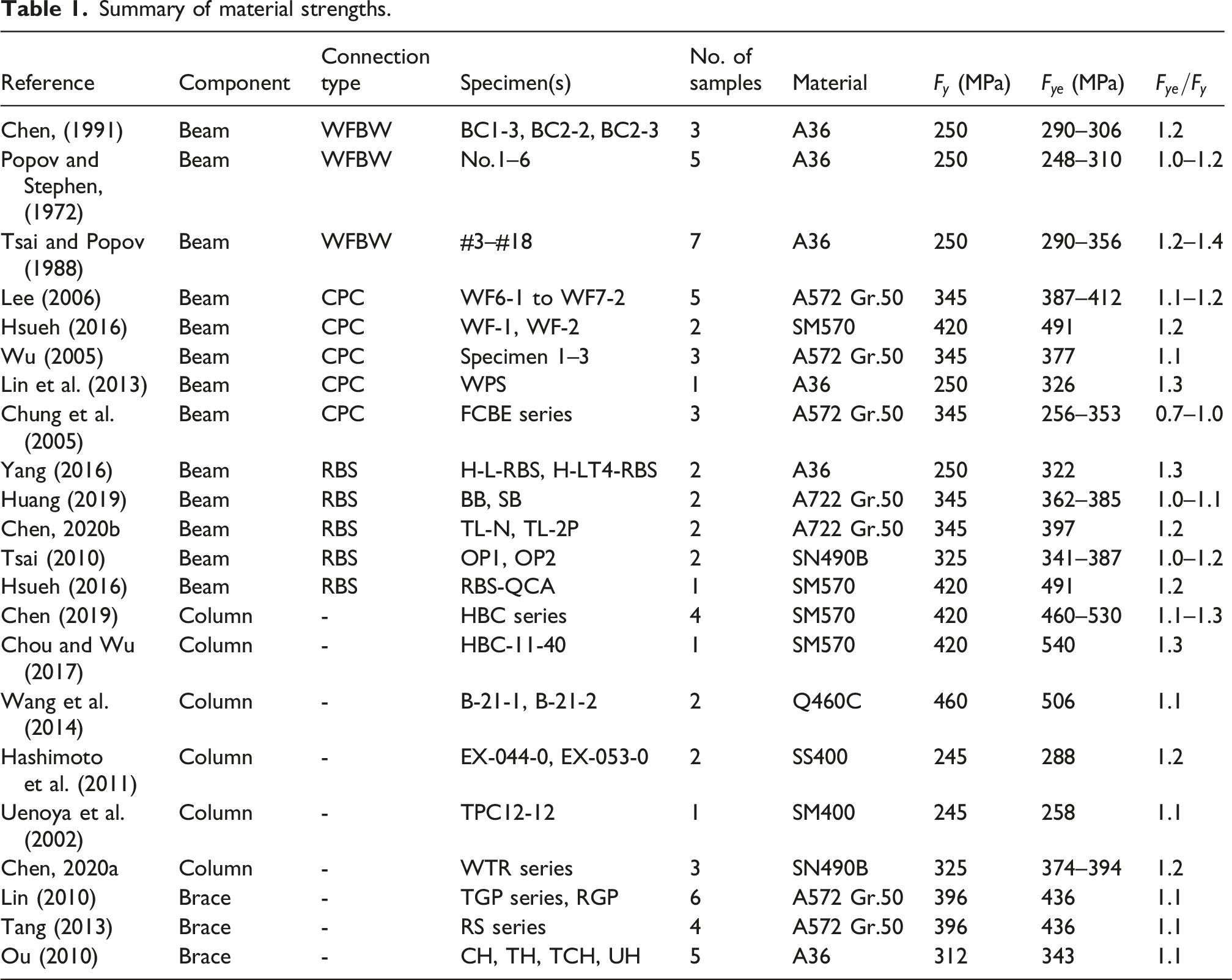
The database advances beyond traditional collections. In addition to conventional grades (ASTM A36, A572 Gr.50), it includes 16 specimens of high-strength steels widely used in Asia: SM570, SN490 B, and Q460 C (Table 1). This compositional diversity supports application to a wide range of modern construction practice.
A key aspect of the calibration is the use of expected strength (
General calibration approach
The nonlinear hinge models were calibrated using a systematic procedure to ensure accuracy and broad applicability. Both strength capacities (yield, peak, ultimate:
Regression analysis was then conducted using least-squares fitting of normalized data, such as
Proposed flexural hinge model for H-shaped beams
The generalized deformation of a beam under flexural loading is illustrated in Figure 1(a). The end rotation is approximated by (a) Bending deformation of a beam, (b) five-point nonlinear hinge model, and (c) normalized form of the hinge model.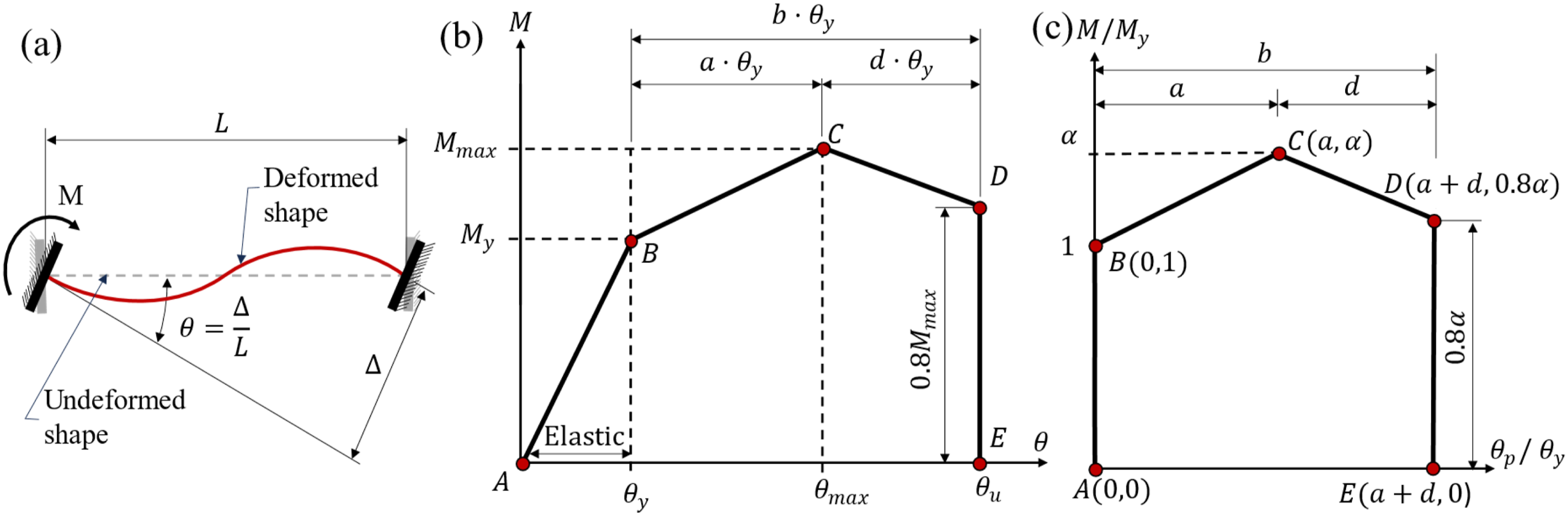
To generalize behavior across member sizes and strengths, the backbone is normalized as shown in Figure 1(c), with
Consistent with the steel component backbone definitions in ASCE 41-23 (2023), the reference moment 
The corresponding chord rotation at Point B is obtained from flexural and shear deformations as: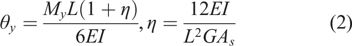
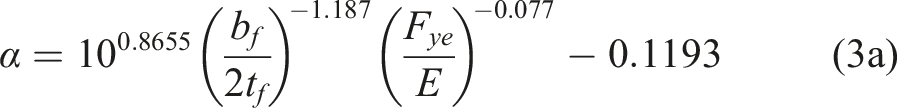
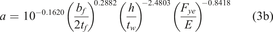
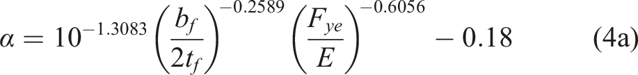
The normalized backbone parameters 1. For WFBW joints: 2. For CPC joints, nonlinear hinge parameters are:

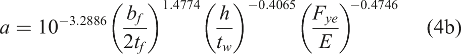

Section parameter collection scopes are 3. For RBS joints nonlinear hinge parameters are:
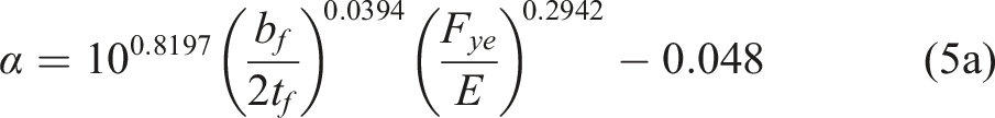
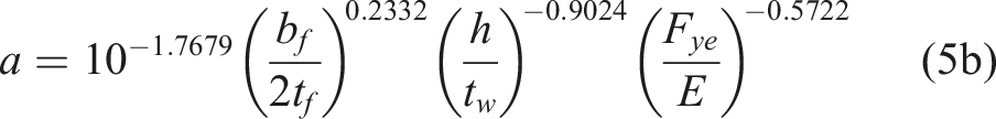

Section parameter collection scope:
The influence of the small-exponent terms is negligible within the calibrated ranges and can be approximated as constants. Specifically,
The values of
It should be noted that the proposed beam backbone models are calibrated against bare steel beam specimens tested without composite floor slabs, consistent with the experimental configurations in the underlying database (Table 1) and the convention adopted by current seismic evaluation standards including ASCE 41-23 and AISC 342-22, which define nonlinear hinge parameters for bare steel sections. The primary effect of a composite floor slab is to introduce asymmetry between positive and negative moment capacities: under positive bending, the slab in compression increases the effective yield moment, while under negative bending, concrete cracking renders the slab contribution negligible. When composite action is significant for a specific project, the reference yield moment
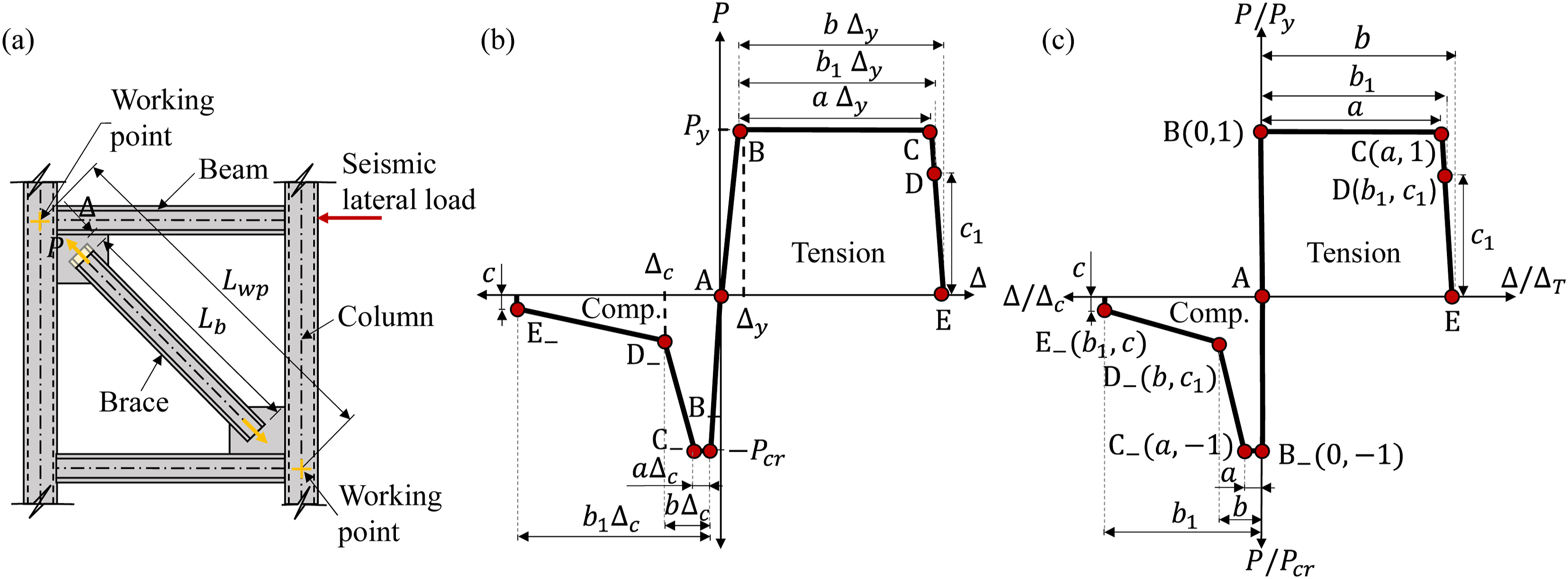
Proposed axial hinge model for braces
The hysteretic behavior of concentric braces is fundamentally asymmetric, characterized by yielding and strain hardening in tension, and buckling-induced strength degradation and pinching in compression. To accurately capture this response, an axial hinge model utilizing distinct normalized backbone curves for tensile and compressive actions is proposed. The model presented in this section is calibrated specifically for H-shaped steel braces, a common brace section type in steel construction. Extension to other section geometries (e.g., HSS, double-angle, or channel braces) would require independent calibration against section-specific experimental data, as local buckling modes, post-buckling degradation paths, and fracture characteristics differ fundamentally across section types.
The formulation of the model begins with the definition of key axial capacities and their corresponding deformations. The tensile yield capacity, (a) Schematic diagram of brace length, (b) Recommended brace nonlinear hinge development diagram, (c) Normalized brace nonlinear hinge backbone curve.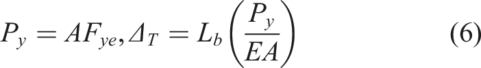
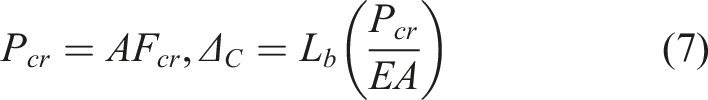
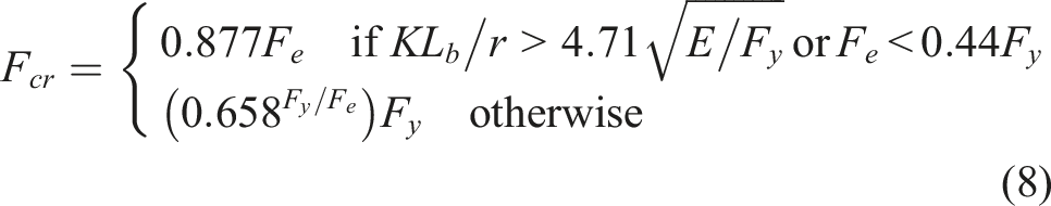
The buckling stress strength 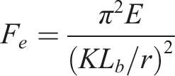
The axial force-deformation response is idealized using a five-point, multi-linear backbone curve for both tension and compression, as depicted in the hinge development diagram (Figure 2(b)). To generalize the model for members of different sizes, the responses are normalized. The normalized backbone curve (Figure 2(c)) defines the five characteristic points in terms of the normalized plastic deformation (labeled
For H-section braces meeting compactness limits (
While for compression they are:
These parameters reflect the fundamentally different failure mechanisms in tension and compression. In tension, the large plateau length (
The calibration is based on H-shaped braces made of A36 and A572 Gr.50 steel, covering three representative section sizes with slenderness ratios between 65.8 and 93.4, which is a range commonly encountered in concentrically braced frame design. Direct application to other brace cross sections, such as hollow structural sections or built-up double angle members, is not recommended without independent recalibration, as these sections exhibit different post buckling degradation mechanisms, for example corner-initiated fracture in HSS following local plate buckling. The backbone parameters are calibrated based on the clear brace length
Proposed flexural-axial hinge model for columns
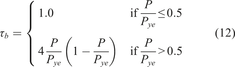
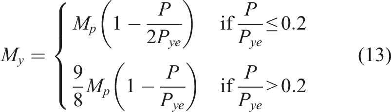
The nonlinear hinge for HSS columns mirrors the beam model with points A-E but incorporates axial load and combined flexural-shear behavior. The yield rotation (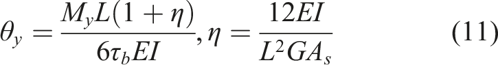
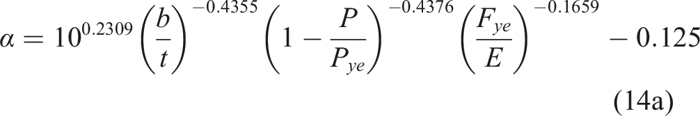
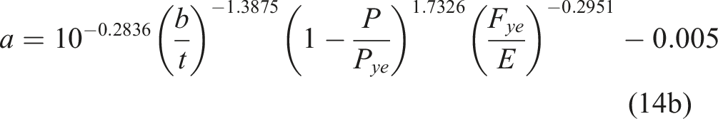

These were validated for HSS columns with
Hysteretic model specification
Cyclic hinge response depends on both the backbone envelope and the rules governing unloading, reloading, and degradation. Advanced phenomenological models such as the Ibarra-Medina-Krawinkler (IMK) family incorporate deterioration in strength and stiffness (Hartloper and Lignos, 2017; Ibarra et al., 2005; Lignos and Krawinkler, 2011). Their parameters, however, are not straightforward to calibrate and are not natively available as standard options in most commercial software. This challenge is evident in recent studies; for example, calibration of the modified Ibarra–Krawinkler model for cold formed hollow sections requires bespoke regression equations for each parameter and still relies on high fidelity experimental data for validation (Bosco et al., 2024). In addition, such models are not natively implemented in standard commercial platforms such as ETABS and SAP2000.
To ensure direct applicability in practical NRHA, the present study adopts a platform-oriented approach in which hysteretic behavior is restricted to built-in element models available in ETABS. This decision reflects a deliberate focus on engineering implementation rather than development of new cyclic deterioration formulations. Accordingly, the primary contribution of this work is the experimental calibration of backbone envelope models, while the hysteretic rules are selected to provide numerically stable and physically reasonable cyclic response within standard software environments.
For components exhibiting stable, symmetric hysteretic response with limited pinching, specifically H-shaped beams and HSS columns, the Kinematic hysteresis model available in ETABS was adopted. Among the built-in options in ETABS, the Kinematic model provides the most appropriate representation of steel flexural behavior: the Isotropic model neglects stiffness degradation and Bauschinger effects, while the Takeda model, originally developed for reinforced concrete, captures pinching and stiffness changes that are not characteristic of compact steel sections. The Kinematic model, illustrated for a beam element in Figure 3(a) and for a column element in Figure 3(b), defines unloading and reloading paths based on the initial elastic stiffness and the backbone envelope. It provides a robust representation of the stable energy dissipation observed in the experimental data for these flexure-dominated members. Kinematic hysteresis model adopted for (a) H-shaped beams and (b) HSS columns.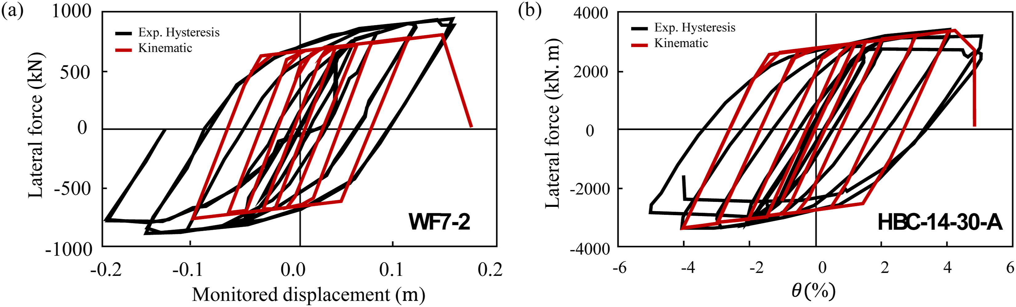
For H-shaped braces, which exhibit asymmetric cyclic response characterized by tensile yielding with strain hardening and compressive buckling with post-buckling degradation and pinching, the Pivot hysteresis model available in ETABS was adopted. Unlike the symmetric Kinematic rule, the Pivot formulation employs scalar parameters that independently govern unloading and reloading stiffness, making it well suited for components dominated by buckling and stiffness asymmetry.
The Pivot parameters were selected to reproduce representative cyclic behavior observed in the experimental database, using specimen UH1620 as a reference case. It is emphasized that the Pivot rule was not newly calibrated as a phenomenological model; rather, it was selected from the built-in options in ETABS, and its parameters were tuned to produce physically realistic pinching and degradation characteristics consistent with H-shaped brace test data. Two bounding cases were first evaluated to assess sensitivity: a high-stiffness case and a low-stiffness (high-pinching) case. As shown in Figure 4(a) and (b), these extreme settings lead to unrealistic responses, either overly stiff unloading or excessive pinching. A balanced parameter set was then adopted to capture intermediate behavior. The resulting response, shown in Figure 4(c), provides reasonable agreement with the experimental envelope of UH1620 in terms of unloading stiffness, pinching severity, and post-buckling degradation. The influence of the post-yield parameter η was found to be negligible, and the ETABS default Pivot hysteresis model behavior: (a) high-stiffness parameter case; (b) low-stiffness (high-pinching) case; (c) recommended parameter set compared with experimental envelope of specimen UH1620 (Ou, 2010).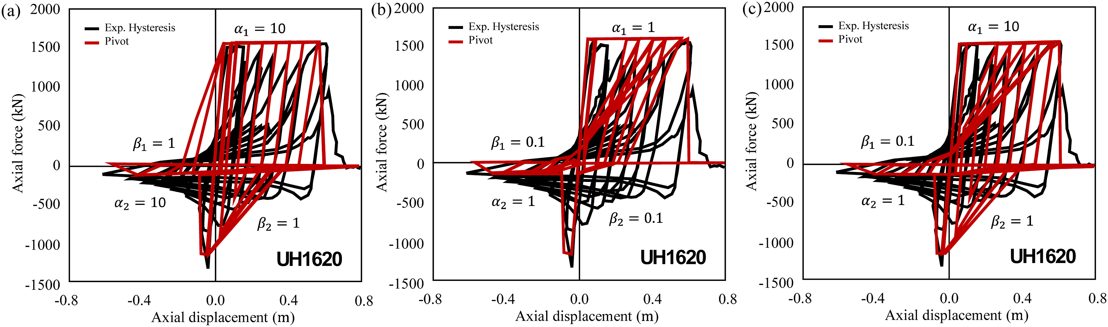
It is noted that the built-in hysteretic rules adopted in this study, particularly the Kinematic model, may produce somewhat fuller hysteresis loops than observed experimentally, leading to a potential overestimation of cyclic energy dissipation. This limitation is inherent to simplified cyclic formulations that do not explicitly capture progressive strength and stiffness deterioration. However, the primary contribution of this work is the experimentally calibrated backbone envelope, which governs the strength and deformation acceptance criteria in ASCE 41-23-based performance assessment. Since key engineering demand parameters such as peak strength, plastic rotation capacity, and residual strength are directly controlled by the backbone and are independent of the cyclic rule, the main conclusions and system-level performance predictions remain unaffected. For applications where cumulative energy dissipation and near-collapse behavior are critical, more advanced degrading hysteretic models (e.g., the IMK family) may be adopted when available in the analysis platform.
Verification against experimental data and code provisions
Following calibration, the proposed hinge models were validated at the component level through systematic comparison with experimental results and established code provisions. The flexural hinge for H-shaped beams was benchmarked against AISC 342-22 (AISC, 2022a); the axial hinge for H-shaped braces was compared with ASCE 41-17 (ASCE, 2017) and AISC 342-22 (AISC, 2022a); and the combined flexural–axial hinge for HSS columns was evaluated against AISC 342-22 (AISC, 2022a) and the model proposed by Chen (2019). These comparisons quantify the predictive accuracy of the proposed formulations relative to current practice.
Model performance was assessed by comparing predicted backbone parameters with values extracted from experimental envelope curves. For strength-related quantities (yield moment 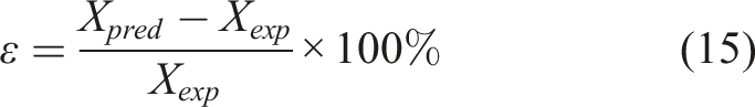
When tests were terminated prior to complete strength degradation, the ultimate deformation was taken as the final recorded point on the experimental envelope. This convention was applied consistently to both the proposed and benchmark models to ensure an equitable basis for comparison. Error statistics are reported as mean percent error and standard deviation, expressed in the form mean ± standard deviation, which jointly describe systematic bias and dispersion. Positive values indicate overprediction, while negative values indicate underprediction.
All experimental envelopes were digitized directly from the original references. Backbone parameters for benchmark models were computed strictly according to their published procedures, without recalibration or adjustment.
Flexural hinges for H-shaped beams
The proposed connection-specific hinge models are validated by comparing their predicted backbone curves against both experimental data and the default models prescribed in AISC (2022a). This comparison provides a basis for evaluating the ability of each modeling approach to represent both strength and deformation capacity across different connection types.
The existing code models adopt a generalized backbone formulation in which key parameters, including post-yield stiffness and plastic rotation limits, are primarily defined using member geometric ratios. While this approach provides a unified modeling framework, it does not explicitly differentiate between connection-specific failure mechanisms. As illustrated in Figure 5 through Figure 7, this simplification leads to observable deviations in predicted backbone behavior for different connection types. Validation of proposed flexural hinge model against experimental data and AISC 342-22 for WFBW connections.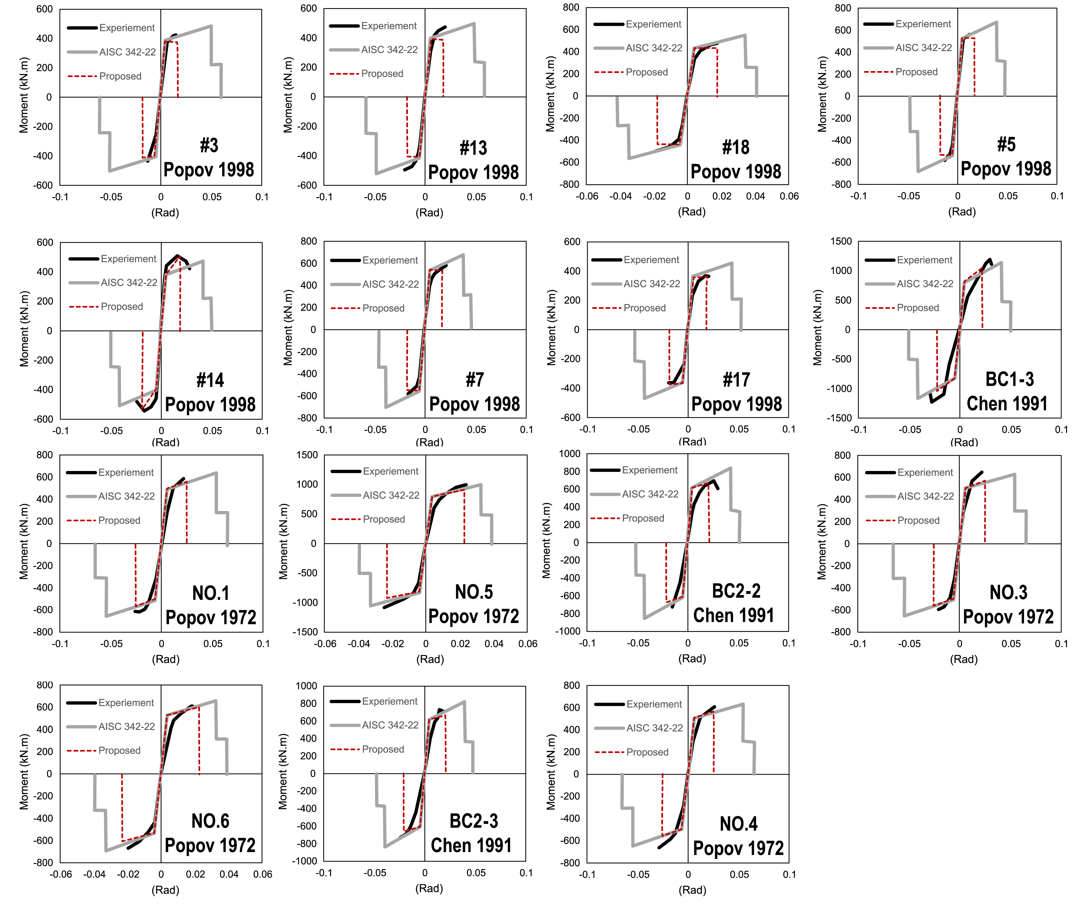
For WFBW connections as shown in Figure 5 (prone to brittle fracture), the AISC 342-22 model severely overestimates deformation capacity. In contrast, for CPC (Figure 6) and RBS connections (Figure 7) which are designed for ductility, the code models generally overpredict both strength and, especially, deformation, with errors for ultimate rotation ( Validation of proposed flexural hinge model against experimental data and AISC 342-22 for CPC connections. Validation of proposed flexural hinge model against experimental data and AISC 342-22 for RBS connections.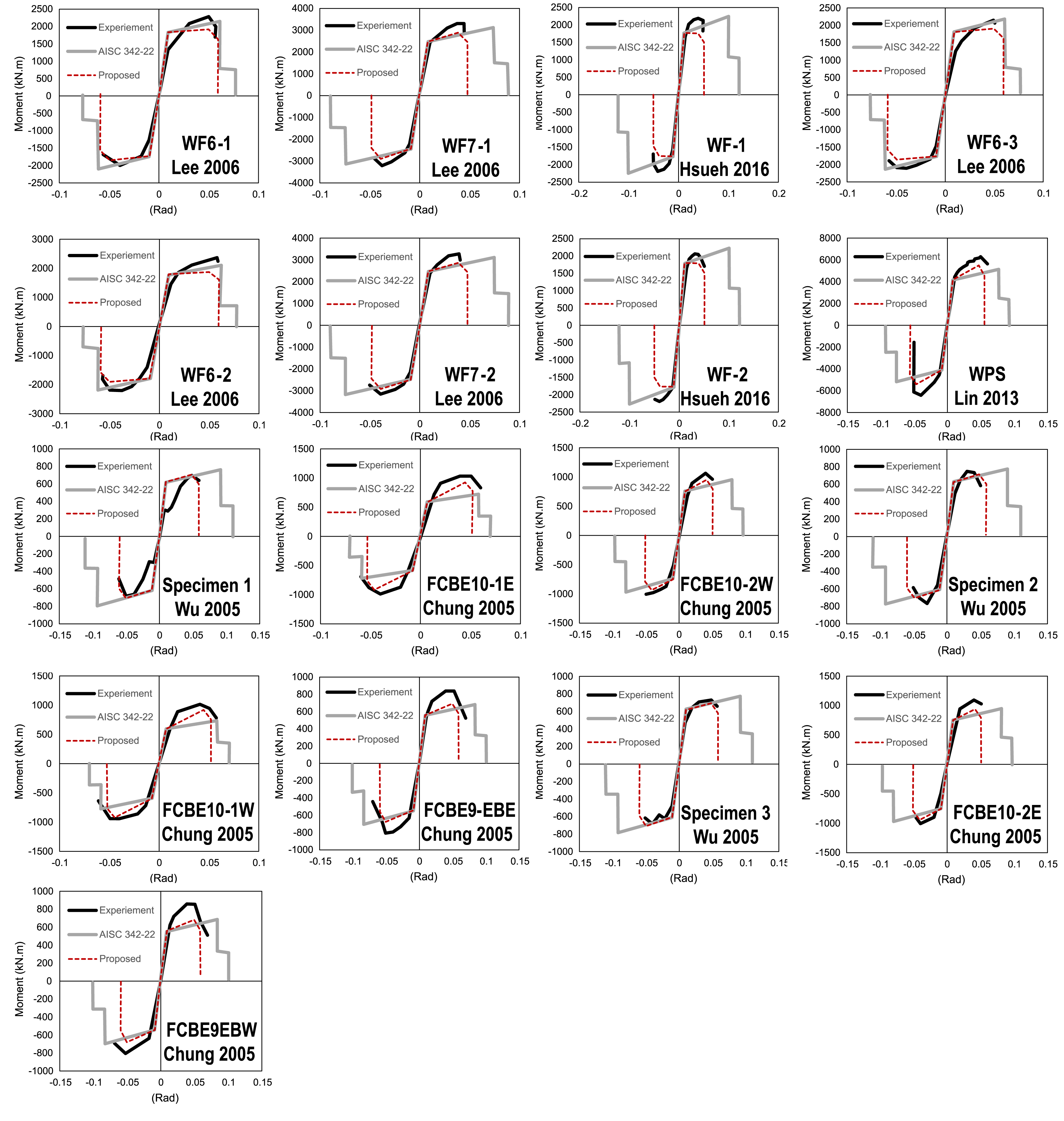
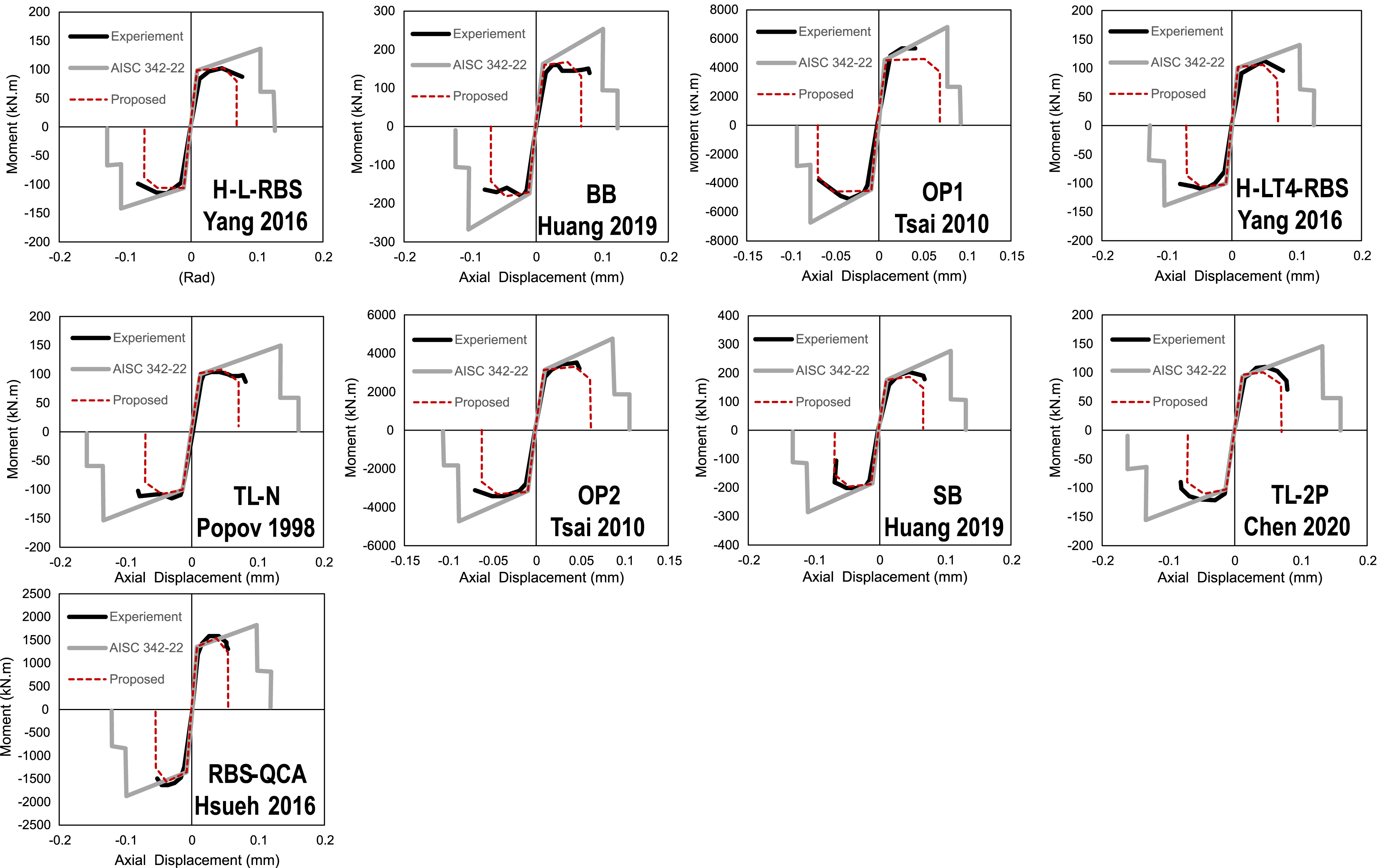
In contrast, the proposed connection-specific models achieve closer and more consistent alignment with experimental behavior across all connection types. The key advantage is their transformative accuracy in estimating deformation capacity, which is the most critical parameter for seismic performance assessment.
The quantitative results underscore the performance of the proposed approach. As illustrated in Figure 8, the error analysis by connection type highlights the performance gains: for WFBW connections (Figure 8(a)), the proposed model reduces the mean error in predicting the rotation at maximum strength ( Error analysis of the proposed hinge model by connection type: (a) WFBW, (b) CPC, and (c) RBS.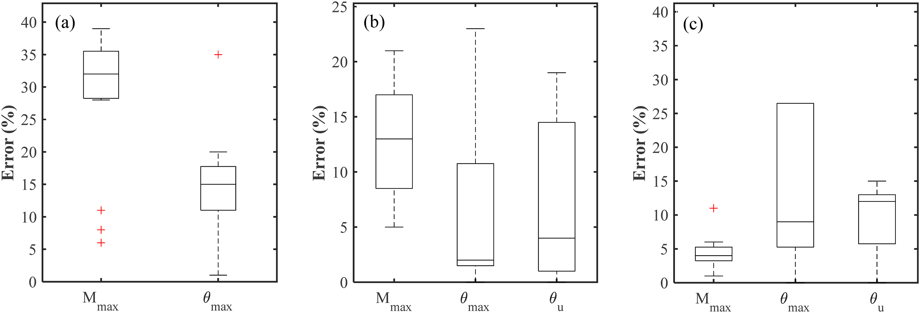
This substantial improvement ensures that the proposed hinge models are more consistent with experimental observations, providing more reliable estimates for performance-based seismic design. These results highlight the importance of connection-specific calibration, demonstrating that the proposed approach captures strength and ductility demands more realistically than current code provisions.
Axial hinges for H-shaped braces
The proposed axial hinge model effectively captures the asymmetric hysteretic behavior of concentric braces, with tensile response governed by yielding and strain hardening, and compressive response dominated by buckling-induced strength loss and pinching. As shown in Figure 9, the model uses distinct backbone curves for tension and compression with a pivot hysteresis rule and demonstrates closer agreement with experiments than ASCE 41-17 and AISC 342-22. Validation of proposed axial hinge model against experimental data, ASCE 41-17, and AISC 342-22 for H-shaped braces.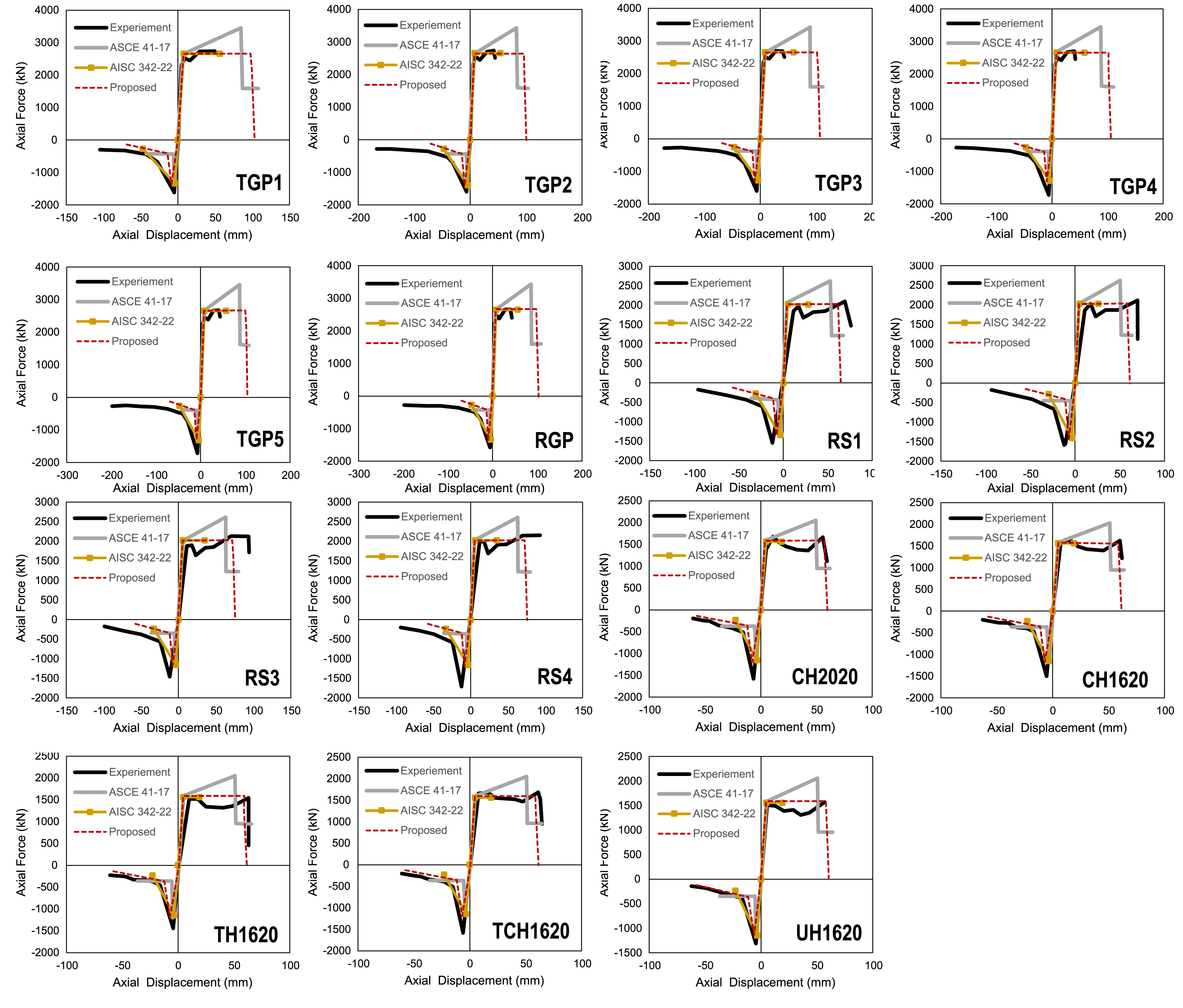
Across most specimens (RS, CH, TH, TCH, UH series), the model accurately reproduces post-buckling degradation, asymmetric pinching, and tensile strain hardening. In contrast, ASCE 41-17 tends to overestimate tensile deformation, while AISC 342-22 is relatively conservative on the tension side, underpredicting strain hardening.
It should be noted that the TGP and RGP specimens were not completed in tension due to equipment limitations, and therefore provide calibration value only on the compression side. The seemingly better performance of AISC 342-22 in these cases reflects incomplete data rather than true predictive accuracy.
It should be noted that both the proposed model and the code-based comparisons (ASCE 41-17, AISC 342-22) shown in Figure 9 pertain exclusively to H-shaped brace sections. Current standards similarly provide section-type-specific modeling parameters, recognizing that backbone characteristics are not transferable across section geometries.
Flexural-axial hinges for HSS columns
The predictive performance of the proposed flexural–axial hinge model for HSS columns is evaluated through comparison with experimental results and existing models, including AISC 342-22 AISC (2022a), and the model proposed by Chen (2019). The validation encompasses axial load ratios ranging from Validation of proposed flexural–axial hinge model against experimental data, AISC 342-22, and Chen (2019) for HSS columns. Error analysis for HSS column nonlinear hinge models: (a) proposed model, (b) Chen (2019), and (c) AISC 342-22.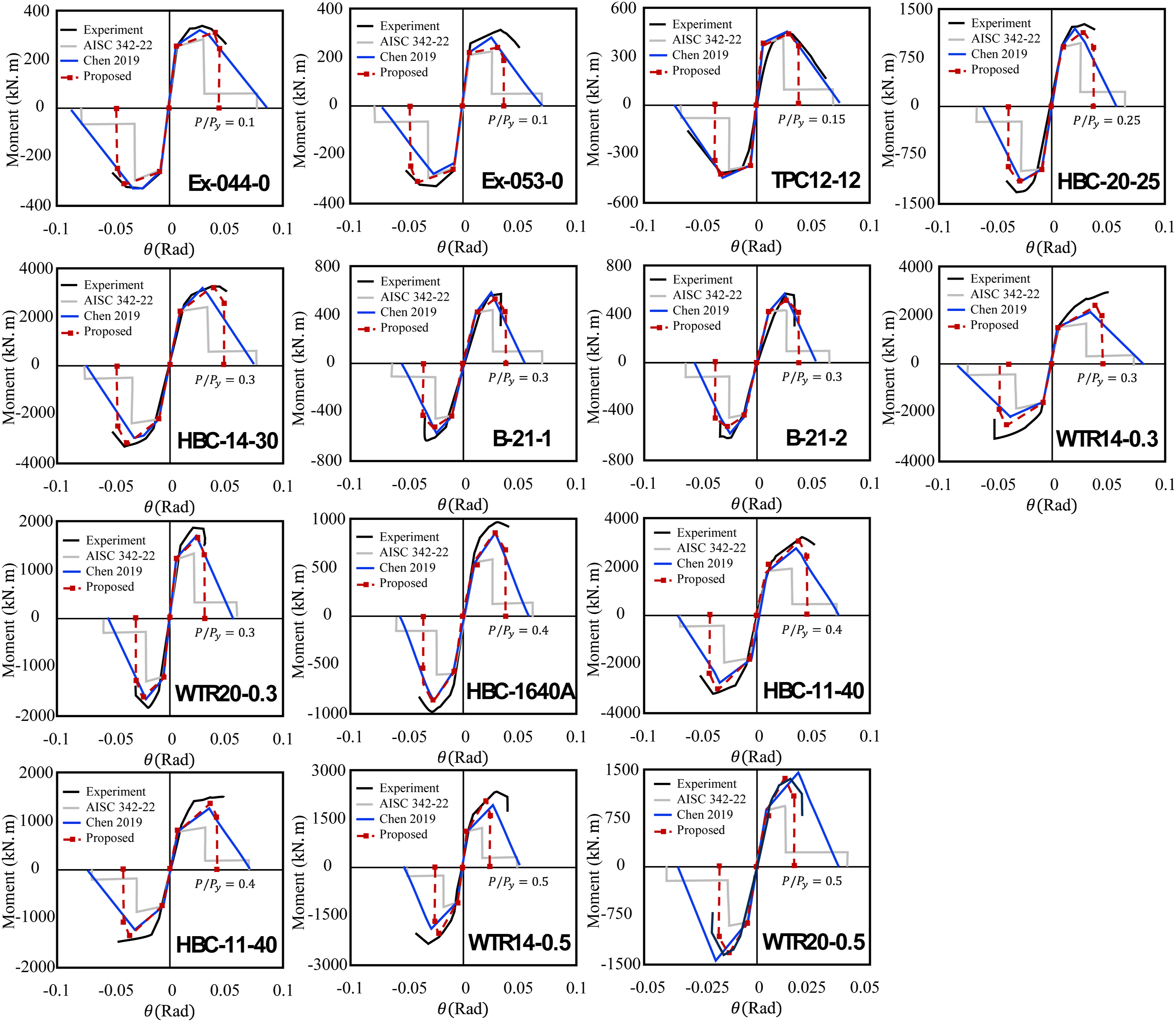
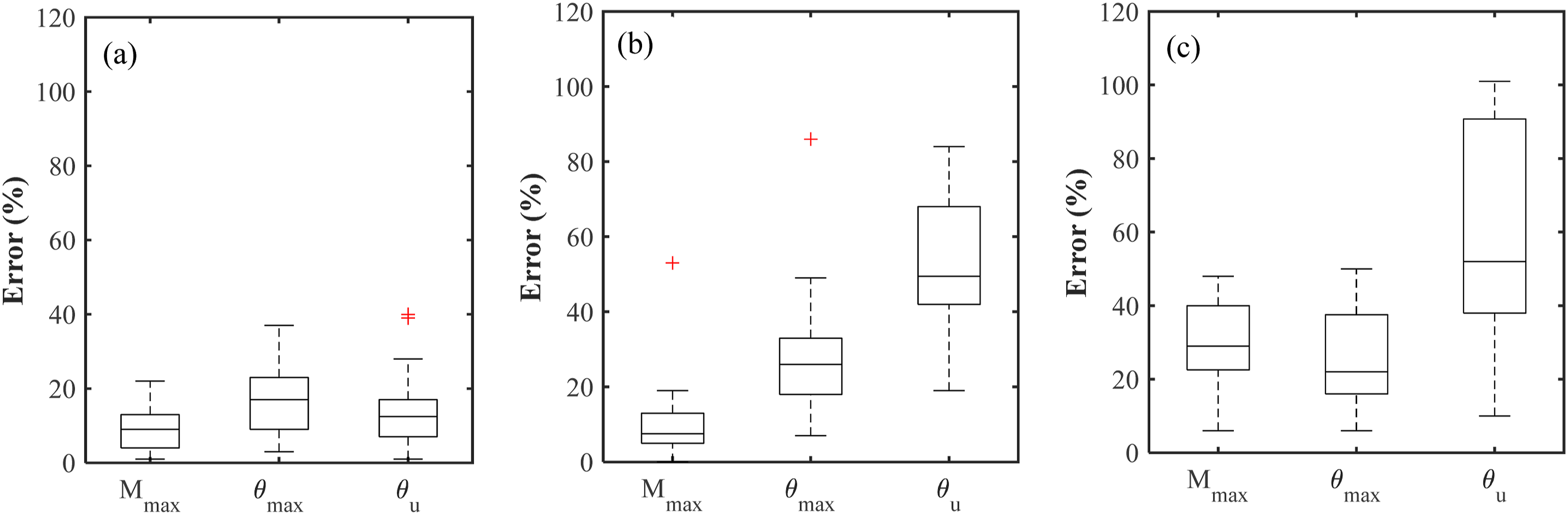
As shown in Figure 11(a), the hinge model developed in this study produces a compact and well-centered error distribution for all response metrics. The mean prediction error in maximum strength is limited to 9% ± 5%, while the rotation at peak strength and ultimate rotation are predicted with mean errors of 17% ± 10% and 16% ± 12%, respectively. The relatively small dispersion indicates stable performance across specimens with varying axial load ratios. Importantly, the model captures the experimentally observed degradation of both strength and ductility with increasing axial demand, demonstrating that the coupled flexural–axial formulation preserves key behavioral trends that govern column performance.
The error distribution associated with the model by Chen (2019), shown in Figure 11(b), reveals a different balance of accuracy. Strength predictions are generally conservative and reasonably accurate, with a mean
Figure 11(c) illustrates the performance of the AISC 342-22 formulation. While the bilinear interaction model moderately reduces error in predicting rotation at maximum strength (
Taken together, the results demonstrate that the proposed hinge formulation achieves a balanced performance in terms of accuracy and consistency compared to the reference models. Its error distributions remain narrow while preserving essential axial load dependence, supporting its suitability for performance-based seismic assessment of HSS columns in practical nonlinear analysis.
System-level application
Modeling framework
The system-level implications of the proposed nonlinear hinge formulations are evaluated using both nonlinear static and nonlinear dynamic analyses of a representative steel building. The objective is to quantify how component-level modeling assumptions influence global seismic response under different analysis frameworks.
All analyses were conducted using ETABS, with hinge properties defined according to the formulations presented in presented earlier in this paper. Flexural hinges were assigned to beams and columns, while axial hinges were assigned to braces where applicable. Hysteretic behavior was modeled using the kinematic and pivot rules described in the hysteretic model specification. This modeling approach reflects a platform-oriented strategy, enabling direct implementation without user-defined elements or external scripting.
Geometric nonlinearity, including P–Δ effects, was explicitly included in all analyses. Gravity loads were applied prior to lateral loading using a combination of 1.0DL + 0.5LL.
Case study building and structural configurations
A single 15-story steel building is considered to isolate the influence of structural system and component modeling assumptions. The structure is located in Taipei’s second seismic zone and is designed for public use. It has a rectangular plan measuring 25.5 m × 24.75 m, with three bays in each direction and a total height of 52.7 m. The structural layout is illustrated in Figure 12(a) to (c), while the braced configuration is shown in Figure 12(d). Case-study building configuration (a) Plan view (b) Elevation view (c) 3D model (MRF) (d) 3D model with braces (CBF).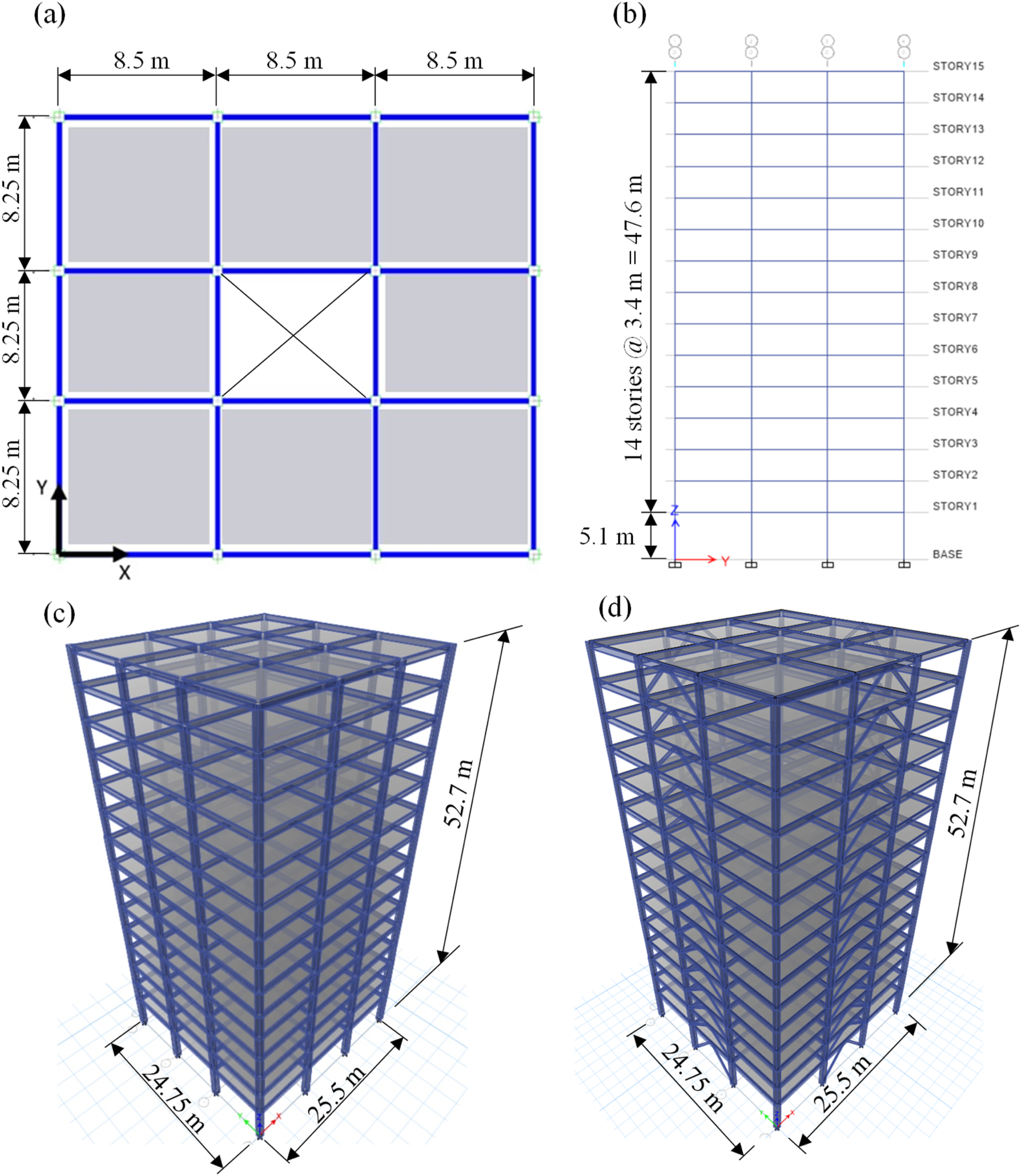
Structural member section sizes and corresponding unit dead loads per story.
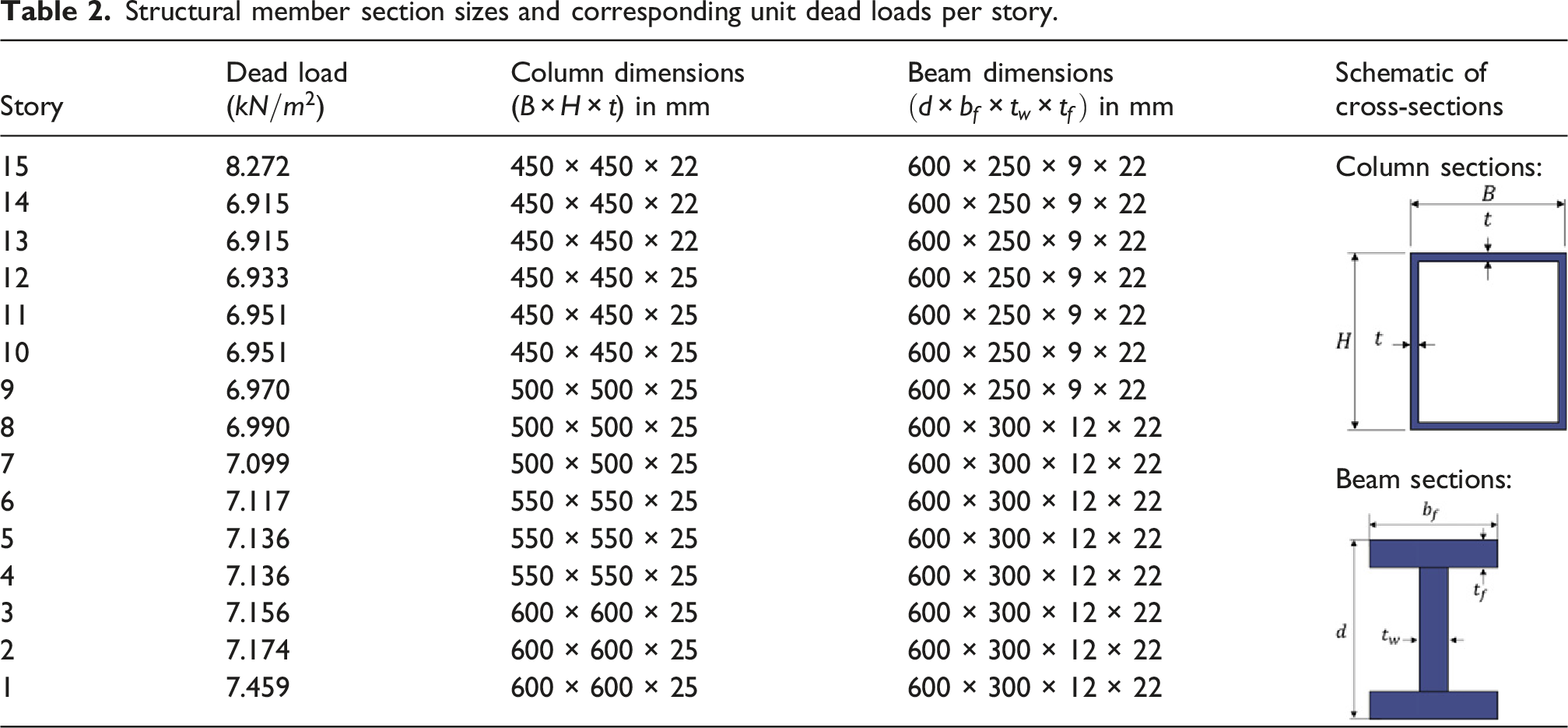
Two lateral force-resisting configurations are investigated using the same structural geometry: 1. MRF, in which lateral resistance provided by beam-column flexural action, and 2. CBF, in which braces introduced into the same layout to provide axial resistance
This approach enables a controlled comparison in which differences in response are attributed directly to system configuration and hinge modeling assumptions.
Analysis procedure
Two complementary analysis approaches are adopted to evaluate the influence of component modeling assumptions.
For the MRF configuration, nonlinear static pushover analysis is employed using a first-mode lateral load pattern. This approach isolates the influence of connection-specific backbone definitions on global strength, deformation capacity, and failure mechanism under controlled loading conditions.
For the CBF configuration, NRHA is performed to capture the inherently asymmetric and cyclic nature of brace behavior, including buckling, strength degradation, and energy dissipation. Static pushover analysis is insufficient to represent these effects; therefore, dynamic analysis is required to evaluate the influence of hysteretic modeling.
This combined framework allows backbone-controlled behavior (MRF) and hysteresis-controlled behavior (CBF) to be examined using the most appropriate analysis method for each system.
For the MRF, four beam hinge models are evaluated: the proposed backbones for WFBW, CPC, and RBS connections (Equations 3–5), and the generalized backbone defined in AISC 342-22. The building is detailed with WFBW connections; therefore, the proposed–WFBW model represents the physically consistent case, while the others provide bounding comparisons.
MRF configuration: Influence of connection-specific backbone selection
A displacement-controlled pushover analysis was performed using a load pattern proportional to the first mode shape. The resulting base shear versus roof displacement relationship for the proposed–WFBW model is shown in Figure 13(a). The pushover curve exhibits a post-yield plateau followed by strength degradation, reaching a maximum base shear of approximately 15,000 kN. Analysis diagrams after nonlinear static pushover. (a) Base shear versus roof displacement relationship, and (b) Converted S
a
versus S
d
relationship.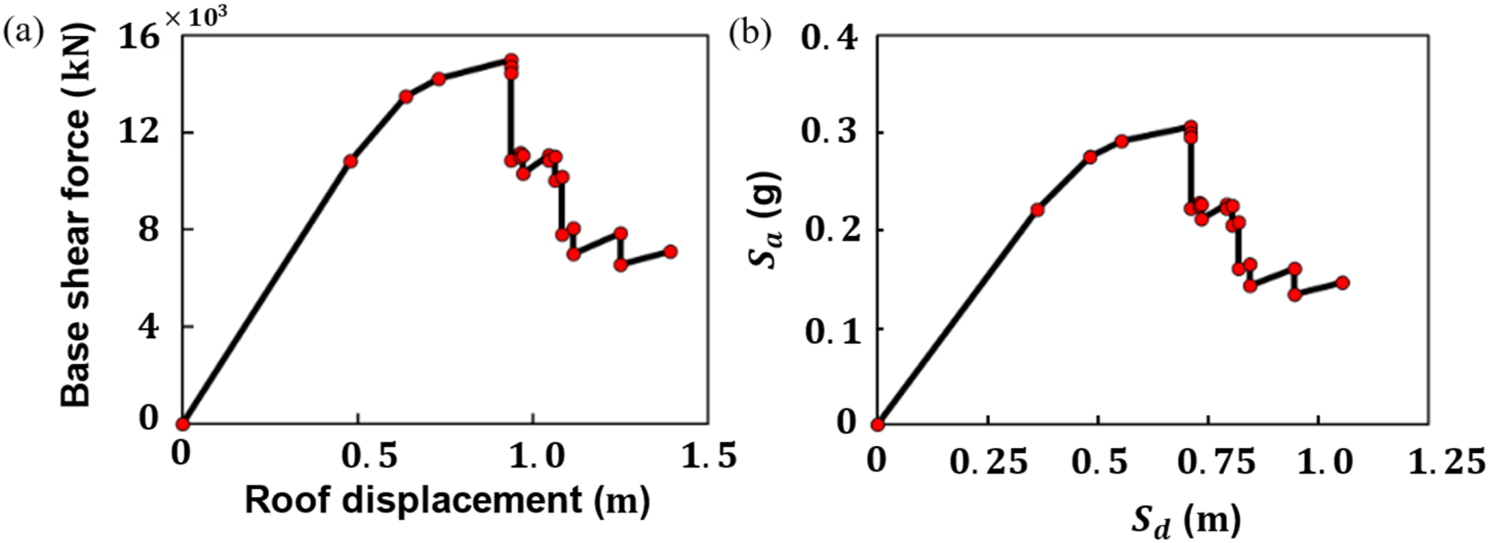
The capacity spectrum method (CSM) was employed to evaluate seismic performance. The pushover curve was converted to Acceleration-Displacement Response Spectrum (ADRS) format, as shown in Figure 13(b). The performance point, representing the intersection of the capacity curve with the demand spectrum, occurs at a spectral acceleration
The pushover responses obtained under the four hinge modeling scenarios are compared in Figure 14. Three important findings emerge, each of which can be traced directly to the component-level backbone characteristics validated in model verification section. Connection-specific backbone models (WFBW, RBS, CPC) versus AISC 342-22.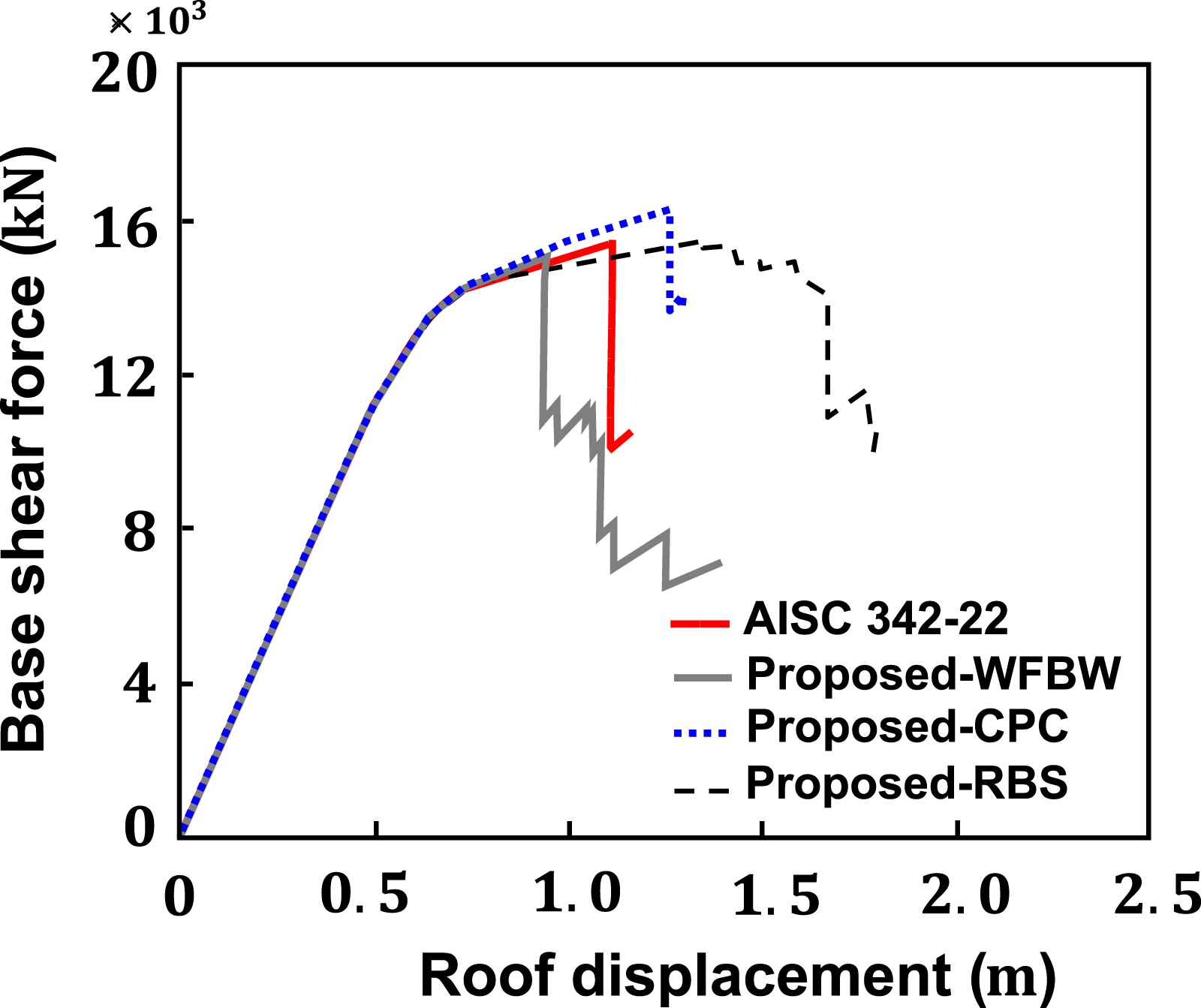
First, the four models produce markedly different global responses despite identical building geometry and member sizes. The proposed–WFBW model reaches peak capacity at the smallest roof displacement (∼0.9 m) and exhibits a sharp post-peak descent, consistent with the zero post-peak deformation (d = 0) and the limited rotation capacity observed at the component level (Figure 5). The Proposed–CPC model sustains a moderately larger displacement (∼1.0 m) with a more gradual descent, reflecting the intermediate ductility (
Second, the AISC 342-22 generalized backbone produces a global response with a peak roof displacement of approximately 1.1 m, which is larger than that of the proposed–WFBW model (∼0.9 m). As discussed in the component-level validation section, the AISC 342-22 backbone tends to provide larger deformation capacities for WFBW connections relative to the proposed formulation (Figure 8(a)). Consequently, differences in the assumed backbone parameters influence the progression of yielding and the distribution of inelastic response within the structural system.
Third, the hinge model determines not only the global ductility but also the predicted failure mechanism. This is evident in the contrasting plastic hinge patterns and inter-story drift profiles discussed below.
The inter-story drift profiles at the first pushover step under the design seismic force are presented in Figure 15 for the proposed–WFBW and AISC 342-22 models. At this loading stage, both models exhibit nearly identical drift distributions along the building height, indicating similar initial global stiffness response under the applied lateral loading. No significant concentration of drift demand or localized irregularity is observed. The overall drift pattern is consistent with the expected response of a regular multi-story moment-resisting frame. Inter-story drift angle verification under design seismic force.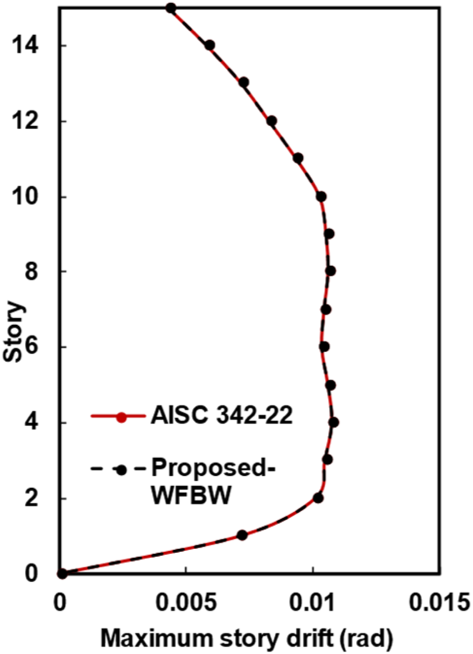
The potential for irregularity was assessed per ASCE 7 and ATC-40 criteria. The lateral stiffness ratio between adjacent stories
The fundamental period from the pushover analysis was
The progression of plastic hinge formation is shown in Figure 16 for both models. The two models exhibit different hinge distribution patterns during the pushover analysis. Nonlinear plastic hinge development diagram for structural model members: (a) proposed (b) AISC 342-22.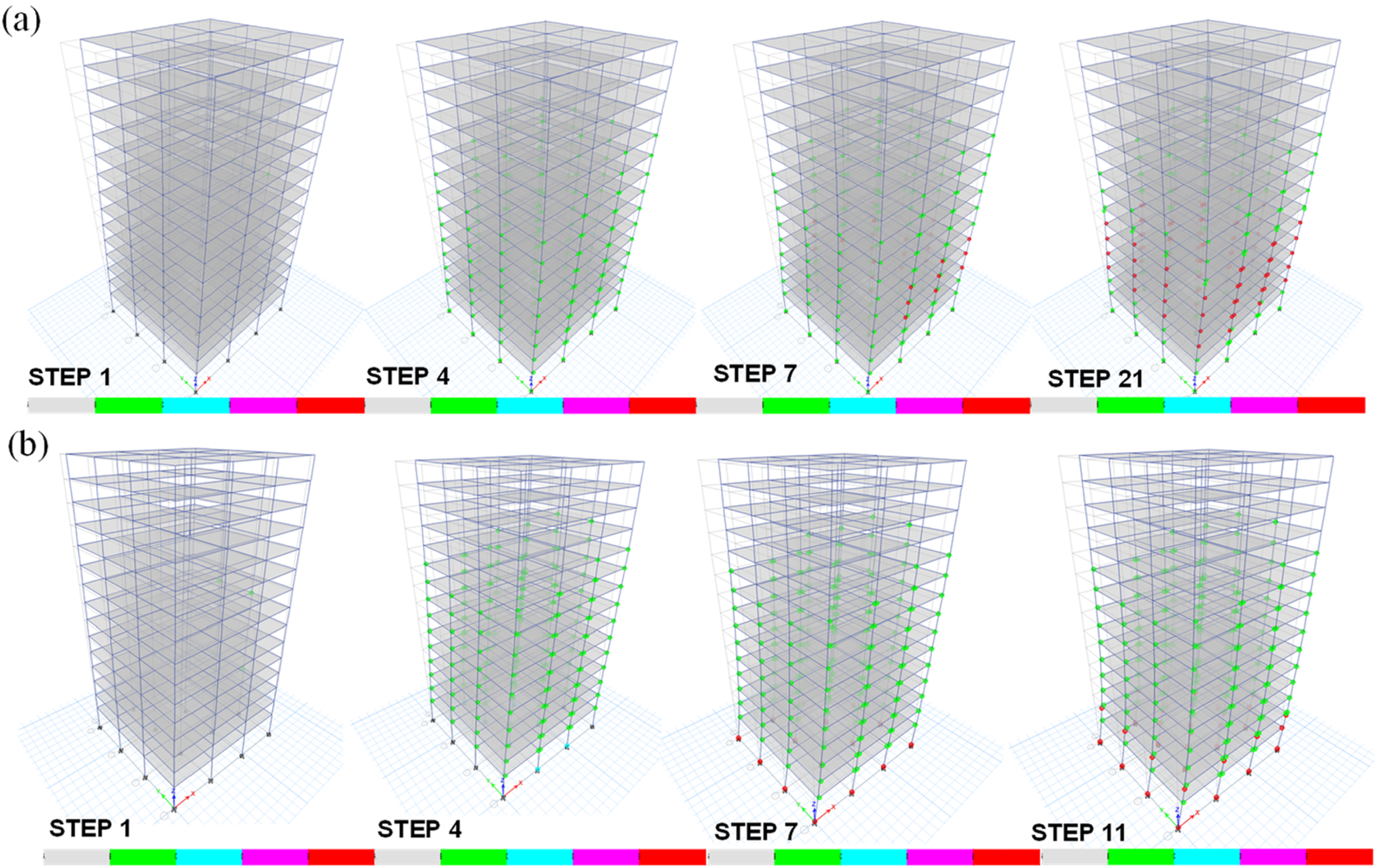
In the proposed–WFBW model (Figure 16(a)), hinges form predominantly in beam ends and propagate upward from the lower stories. Column hinges remain in the elastic or early yield range. This strong-column-weak-beam pattern is consistent with the proposed beam backbone for WFBW connections, which assigns a limited plastic rotation capacity (d = 0) that causes beams to exhaust their deformation capacity before columns are significantly loaded.
In the AISC 342-22 model (Figure 16(b)), plastic hinges are more frequently observed in column elements at lower stories. This difference is associated with the adopted backbone characteristics, where larger assumed beam deformation capacity and relatively lower column strength influence the distribution of inelastic response between beams and columns. As a result, the two modeling approaches produce different system-level hinge patterns under the same loading protocol.
Representative moment–rotation responses extracted from individual beam and column hinges during the pushover analysis are shown in Figure 17. In the proposed–WFBW model (Figure 17(a)), the beam hinge (B15H5, B600 × 300 × 12 × 22) reaches its backbone limit at approximately 2% plastic rotation, followed by a rapid strength reduction characteristic of the adopted WFBW backbone definition. The corresponding column hinge (C12H31, C600 × 600 × 25) develops limited rotational demand relative to the beam hinge response while remaining within the predefined backbone range. Nonlinear plastic hinge development relationship diagrams for a beam, and column members: (a) proposed; (b) AISC 342-22.
In the AISC 342-22 model (Figure 17(b)), the beam hinge accommodates substantially larger plastic rotations, extending to approximately ±12.5%, consistent with the larger deformation capacity assumed in the generalized code-based backbone formulation. The column hinge also develops noticeable inelastic deformation, with response characteristics differing from those observed in the proposed model. These differences in hinge response are consistent with the distinct backbone assumptions adopted in the two modeling approaches.
These component-level responses within the system analysis are fully consistent with the standalone validation results against experimental data and code provisions: the proposed backbone accurately predicts the limited rotation capacity of WFBW connections (mean
CBF configuration: Influence of brace hinge modeling
The second configuration considers the same building with the addition of concentric braces, forming a CBF. Unlike the MRF analysis, which focuses on backbone-controlled behavior, the CBF response is governed by cyclic and asymmetric brace behavior. Therefore, NRHA is adopted to evaluate system performance.
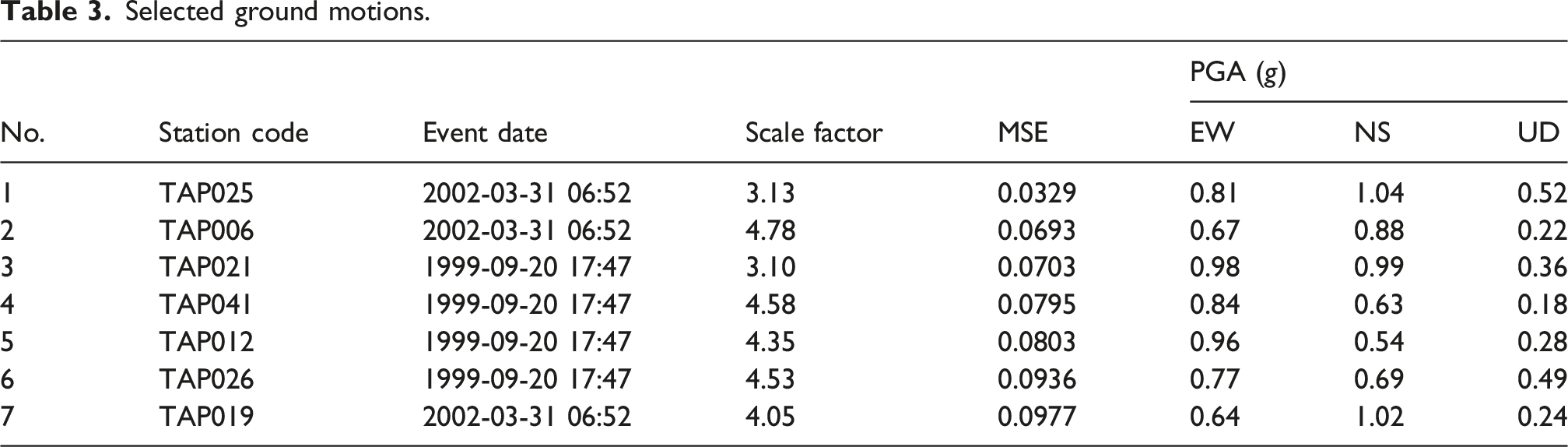
The lateral system comprises CBFs in both orthogonal directions, with H-shaped braces (H294 × 200 × 8 × 12,
Selected ground motions.
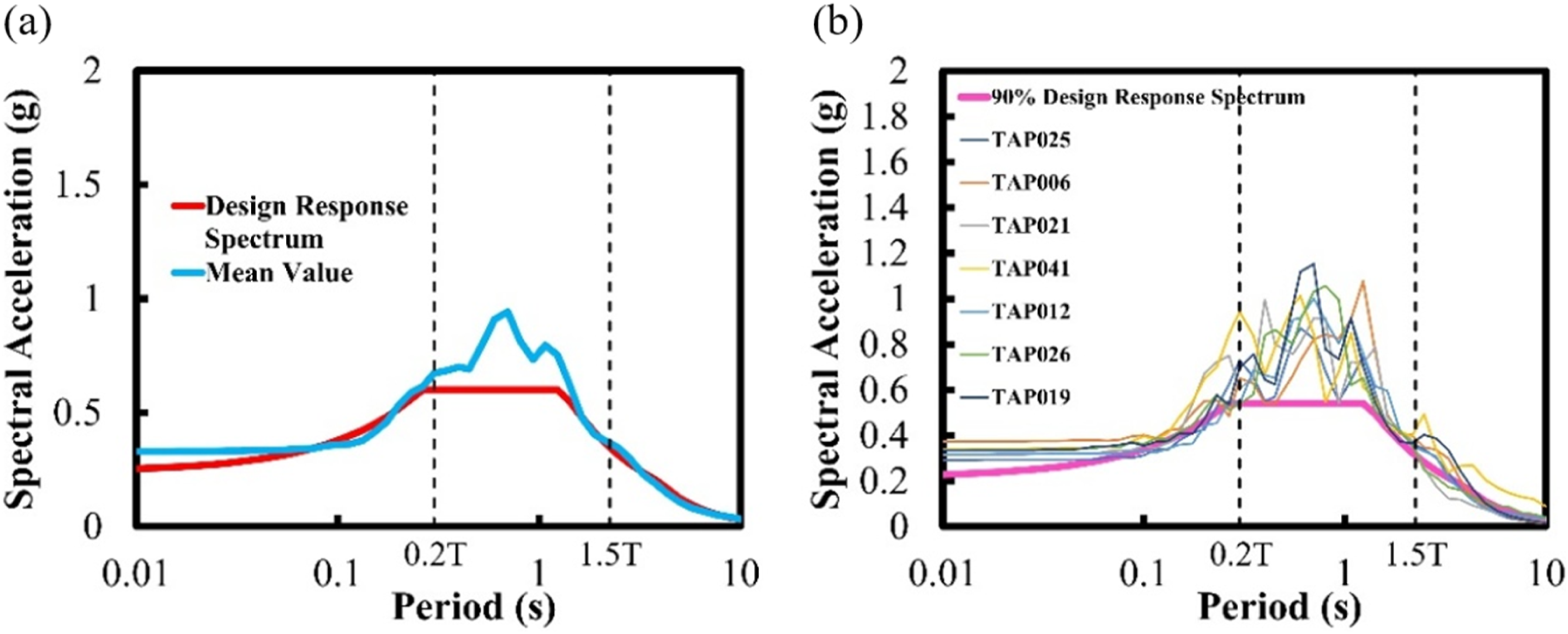
Selected ground motion response spectra. (a) Comparison of design response spectrum and mean scaled ground motion spectrum. (b) Scaled ground motion response spectra from seven selected earthquake records with a 2% damping ratio, compared against the 90% design response spectrum.
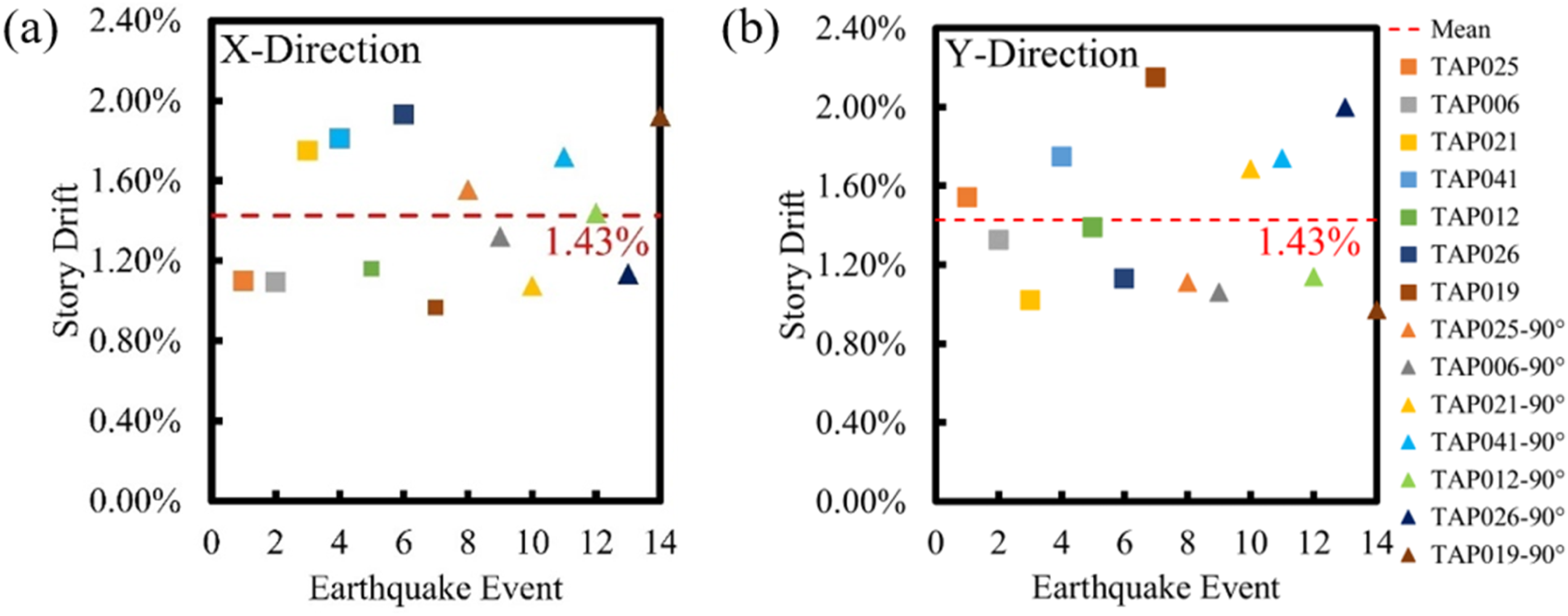
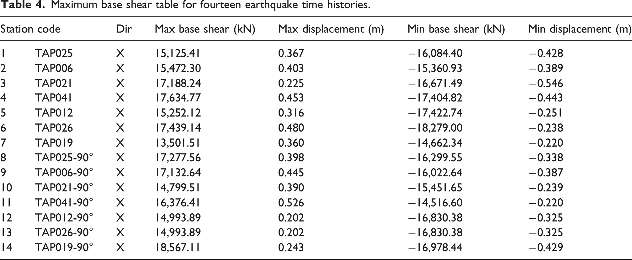
The NRHA was performed using the Hilber–Hughes–Taylor integration scheme with a damping ratio of 0.02. The maximum inter-story drift ratios over all stories and ground motions are presented in Figures 19 and 20. As shown in Figure 20, a peak inter-story drift of 2.15% was recorded under the TAP019 ground motion. However, consistent with established protocols for NRHA, seismic performance is evaluated based on the mean maximum inter-story drift across the complete ground motion suite, rather than on isolated peak responses from individual records. The calculated mean maximum drift was determined to be 1.43%, which falls below the 1.5% threshold prescribed for structures with an importance factor of Inter-story drift angle distributions for 14 ground motion records. Maximum inter-story drift ratios for each earthquake event: (a) X-direction, and (b) Y-direction.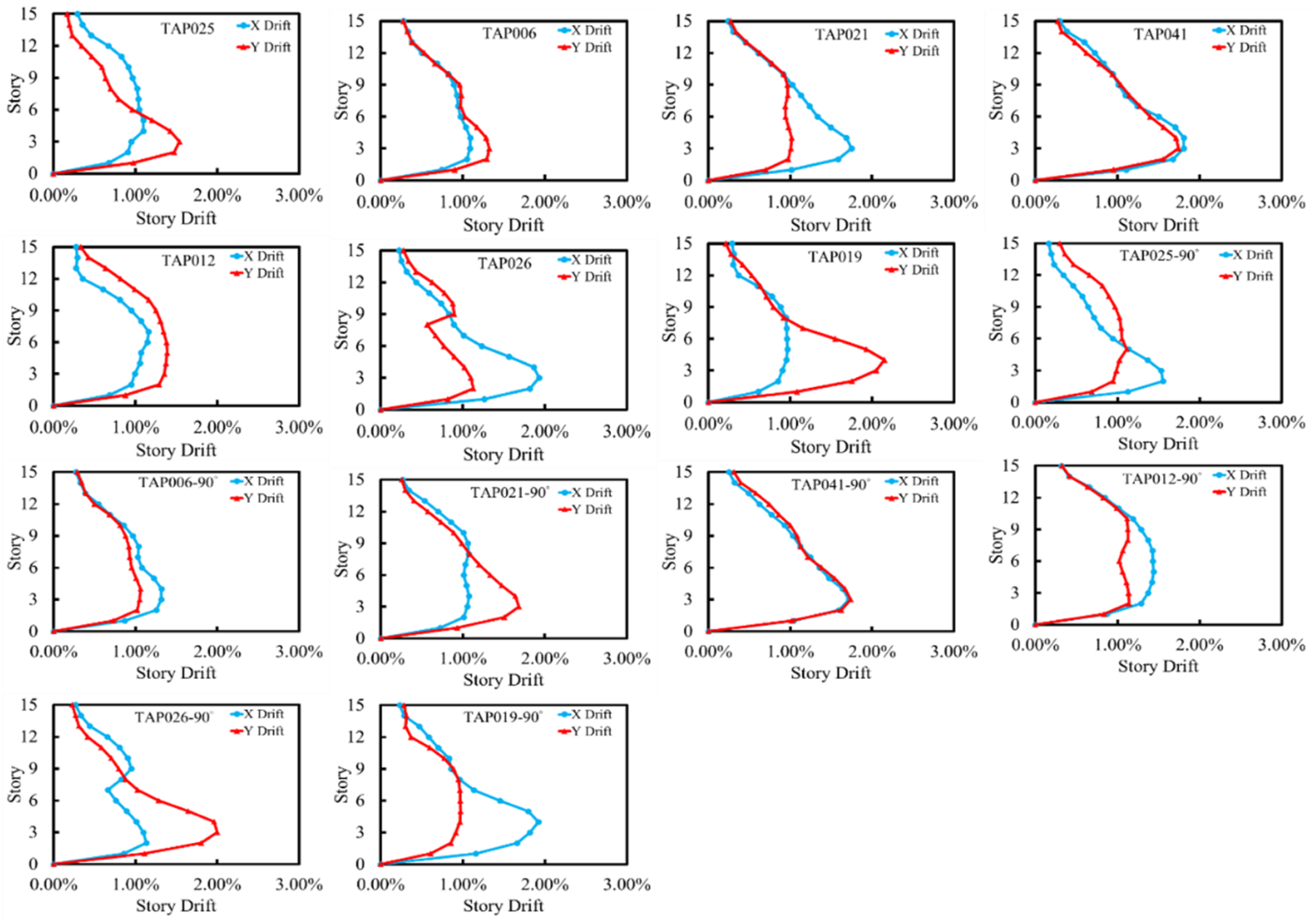
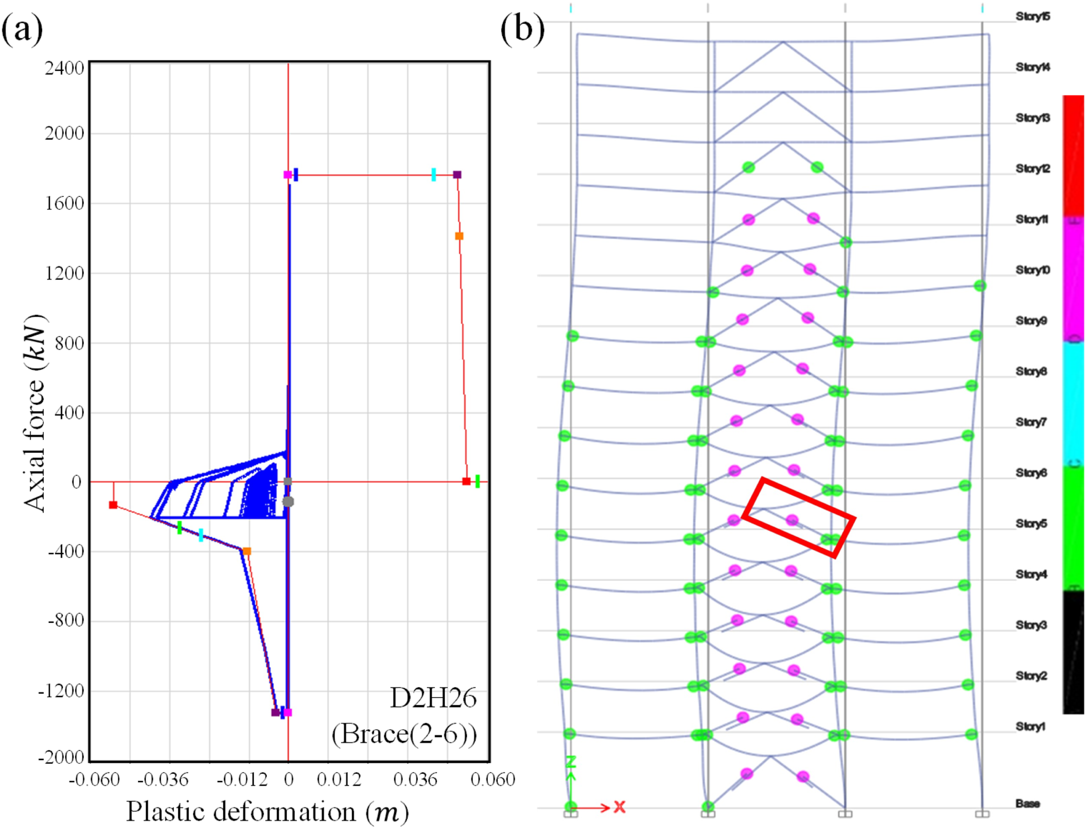
The hysteretic behavior of individual components highlights the model’s ability to reproduce key inelastic mechanisms. Figure 21 illustrates stable, symmetric loops for beams (a) and columns (b), consistent with the kinematic formulation. In contrast, braces display pronounced asymmetry, with pinching and strength degradation under compression and strain hardening in tension, features effectively captured by the pivot hysteresis model (Figure 22). The brace response demonstrates the model’s capacity to simulate post-buckling degradation and energy dissipation characteristic of CBFs. Hysteresis loops for (a) a beam and (b) a column element. (a) Brace force-deformation hysteresis and (b) corresponding deformed shape.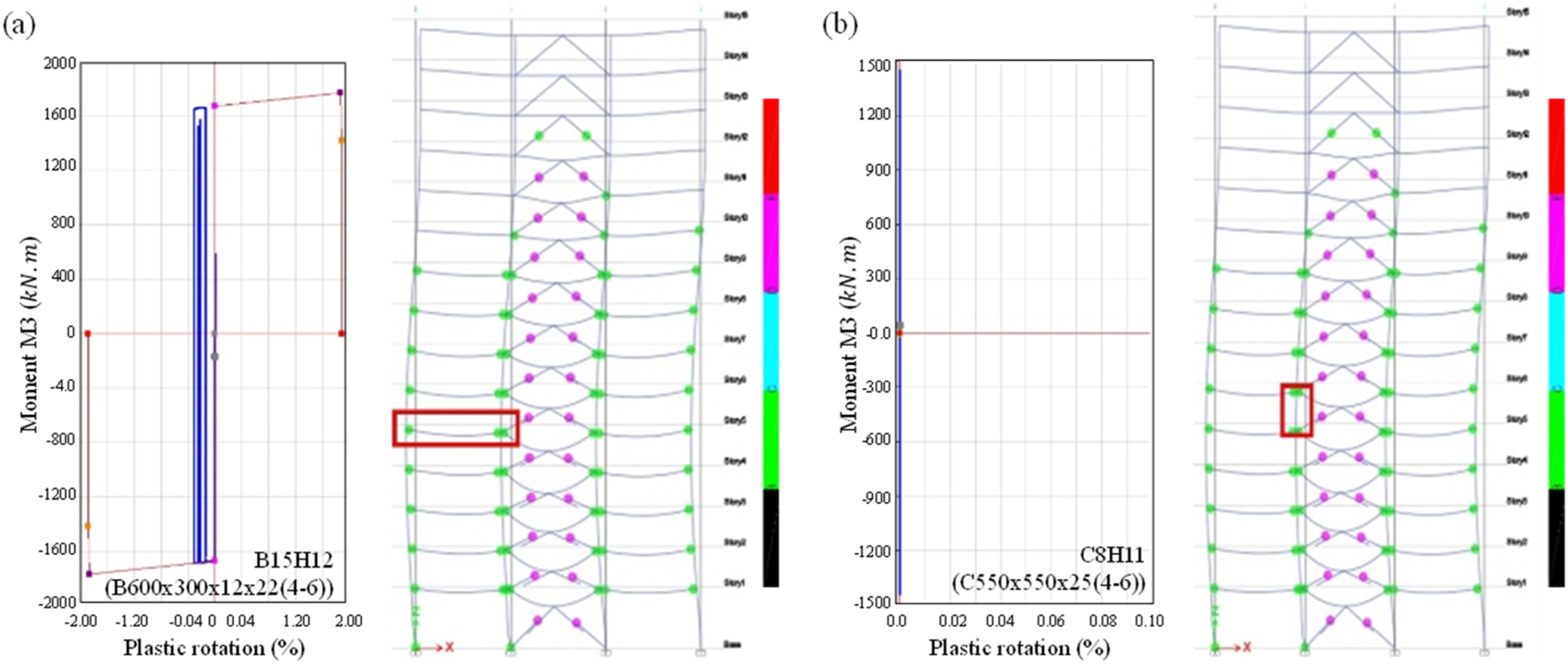
Maximum base shear table for fourteen earthquake time histories.
Conclusions
This study developed experimentally calibrated nonlinear hinge models for three component classes in steel MRFs and CBFs: H-shaped beams, H-shaped braces, and HSS columns. Based on regression analysis of 66 cyclic tests, the proposed formulations are intended for direct implementation in commercial analysis software and provide improved representation of component behavior compared with generalized code provisions, particularly for modern high-strength steels. The main findings are summarized as follows: 1. The proposed flexural hinges effectively capture the distinct inelastic characteristics of WFBW, CPC, and RBS connections. By moving beyond generalized parameters, the models reduce dispersion in deformation capacity predictions, lowering ultimate rotation errors to below 15%. 2. The axial hinge model accurately reproduces the fundamental asymmetry of H-shaped braces through distinct tension and compression backbones. It reliably captures post-buckling degradation and tensile strain hardening, reducing the mean absolute error in buckling strength predictions to 5.8%. 3. The proposed HSS column hinges directly embed axial load effects into the backbone formulation. This approach achieves a balanced accuracy, with mean errors of 9% for strength and 16% for ultimate rotation, while properly capturing ductility degradation under elevated axial demands. 4. A pushover analysis of a 15-story steel moment-resisting frame demonstrates that these component-level improvements are important for global response prediction. The connection-specific models predict a strong-column–weak-beam mechanism, whereas generalized code backbones show different hinge distributions due to higher beam ductility assumptions.
The proposed models are calibrated based on quasi-static cyclic tests of H-shaped beams (WFBW, CPC, and RBS connections), H-shaped braces, and welded HSS box columns. The validity range is defined by the slenderness ratios, yield strengths, and axial load ratios used in the regression analysis. Application outside these ranges, or to section types not included in the database (e.g., wide-flange columns, composite beams, HSS or double-angle braces, circular hollow sections, CFST members), should be supported by additional experimental evidence. The models do not explicitly include strain-rate effects, low-cycle fatigue, or elevated temperature effects, and system-level validation is limited to monotonic pushover analysis.
Future research should address these limitations by (1) expanding the experimental database to include broader section geometries, steel grades, and connection configurations, with particular emphasis on composite floor slab effects in beam backbones and section types prevalent in international practice; (2) extending the framework to composite members such as CFST columns; (3) developing degrading hysteretic rules for accurate cyclic energy dissipation and strength deterioration in nonlinear response history analyses; and (4) incorporating large-scale experimental validation, including shake-table and full-frame subassembly tests, to physically verify predicted failure mechanisms and dynamic responses under realistic seismic demands.
Footnotes
Acknowledgments
The authors thank the NCREE for supporting this research.
Author contributions
All authors contributed to the study conception and design. Material preparation, data collection, and analysis were carried out by Min-Lang Lin, Chao-Hsun Huang, Hui-Yu Chang, and Mojtaba Fathisepahvand. The first draft of the manuscript was written by Mojtaba Fathisepahvand, and all authors reviewed and commented on previous versions of the manuscript. All authors read and approved the final version.
Funding
The authors received no financial support for the research, authorship, and/or publication of this article.
Declaration of conflicting interests
The authors declared no potential conflicts of interest with respect to the research, authorship, and/or publication of this article.
Data Availability Statement
The datasets during the current study are available from the corresponding author on reasonable request.