






Abstract
Fiber reinforced polymer (FRP) has been increasingly used in combination with concrete, steel, and other materials to form novel composite structural members owing to its excellent durability and high strength-to-weight ratio. Recently, a novel type of FRP-steel-concrete composite member (FSCM) including a truncated elliptical FRP tube and a concrete-encased steel I-section, was developed at The Hong Kong Polytechnic University. FSCMs can serve as ductile coupling beams in coupled shear wall systems, or as columns when lateral loading in one principal direction is considerably larger than in the other. An experimental study on compressive behaviour of such FSCM based on tests of 18 specimens (including 13 FSCMs and five corresponding concrete-filled FRP tubes) are presented in this paper. The test parameters include the thickness of FRP tubes and the cross-sectional dimensions of the embedded steel I-sections. It is shown that FSCMs with properly designed FRP tubes and steel I-sections can provide effective lateral confinement to the concrete infill, enabling the specimens to achieve satisfactory load-carrying capacity and ductility. The additional confinement provided by the steel I-section can increase the axial strength of the confined concrete in the post-yielding stage. Within the range investigated, variations in the steel I-section dimensions have limited influence on the overall structural performance of the FSCMs, whereas the FRP tube thickness exerts a more significant effect.
Keywords
Introduction
Fiber-reinforced polymer (FRP) has received extensive application in the structural engineering because of its high strength-to-weight ratio and excellent durability (Lam and Teng, 2003; Mirmiran and Shahawy, 1997; Teng et al., 2003; Teng and Lam, 2002, 2004; Wang and Wu, 2008; Xia et al., 2023). Among the various existing applications of FRP in structural engineering, an emerging one is to use FRP in combination with typical conventional construction materials (e.g., steel, concrete, wood, etc.) to form novel hybrid structural members. Various types of such novel structural members have been proposed in existing studies (e.g., Teng and Lam, 2002; Xia et al., 2025; Yu, 2007) and their structural advantages such as high strength, good ductility and durability due to the combined use of FRP and conventional materials have been well demonstrated (e.g., Ozbakkaloglu, 2013; Teng and Lam, 2002). It is well known that for concrete-filled circular FRP tubes, the circular FRP tubes act in pure lateral tension to provide uniform lateral confinement, which represents the highest confinement effectiveness of FRP tubes (Teng and Lam, 2004). While for concrete-filled noncircular FRP tube, such as concrete-filled rectangular FRP tubes (e.g., Zeng et al., 2018) and concrete-filled elliptical FRP tubes (e.g., Liu et al., 2026; Teng and Lam, 2002) which is highly relevant to the current study, the FRP confinement is non-uniform and the confinement effectiveness of the FRP tubes is relatively low as parts of FRP tubes act in combined lateral bending and tension to restrain the lateral expansion of concrete (e.g., Zeng et al., 2018). To address this issue, technologies such as curvilinearization of non-circular sections (e.g., Zeng et al., 2021; Zhu et al., 2020) and use of embedded steel sections to provide additional confinement (e.g., Huang et al., 2017) have been developed.
Over the past two decades, hybrid FRP-steel-concrete members (FSCMs) have attracted increasing research interest (Cao et al., 2019; Chan et al., 2026; Chen et al., 2020; Huang et al., 2017, 2018; Idris and Ozbakkaloglu, 2014; Ozbakkaloglu and Louk Fanggi, 2015; Pan et al., 2023; Ren et al., 2020; Teng et al., 2007; Yu, 2007; Yu et al., 2006, 2010b, 2016; Zakaib and Fam, 2012). A typical FSCM consists of an FRP outer tube, a concrete infill and an embedded steel section (e.g., steel I-section, steel tube). The advantages of FSCMs have been well demonstrated in many relevant studies: (1) the FRP tube acts as an anti-corrosion protective jacket and provides highly effective lateral confinement to the concrete and steel; (2) the concrete core exhibits high strength and ductility due to the lateral confinement from the FRP tube as well as the embedded steel section; (3) the buckling of the steel section is well delayed or restrained by the confined concrete, allowing the compressive strength of steel to be fully utilized (Huang et al., 2018, 2021; Ren et al., 2020). Although various forms of FSCMs have been proposed, most existing studies have focused on FSCMs as columns (i.e., FRP-steel-concrete composite columns, FSCCs), with only a limited number examining FSCMs as beams, where promising potential has been demonstrated (e.g., Idris and Ozbakkaloglu, 2014; Yu et al., 2006). Against the above background, a novel type of FSCM was recently proposed at The Hong Kong Polytechnic University (Han et al., 2026). This novel FSCM consists of a truncated elliptical FRP outer tube and an inner concrete-encased steel I-section. Owing to the truncated elliptical cross-sectional shape and the inherent structural advantages of FSCMs, the proposed FSCM offers the following advantages: (1) the steel I-section can extend to the outermost fiber to fully develop its flexural capacity, as concrete cover is no longer needed due to the FRP outer tube; (2) shear strength can be effectively increased due to the FRP outer tube with fibers oriented close to the hoop direction; (3) the flat side of the FRP outer tube can be well connected to the superstructure (e.g., slab) without the risk of interference with reinforcement during construction (Han et al., 2026). This configuration is particularly well suited for use as ductile coupling beams in coupled shear wall systems and as columns when lateral loading in one principal direction is considerably larger than in the other.
Han et al. (2026) demonstrated that the proposed FSCM possesses excellent compressive performance using small-scale specimens (sectional height = 152.4 mm) with a single cross-sectional configuration. To systematically investigate the structural behaviour of the composite action among FRP, steel, and concrete in this novel FSCM, axial compression tests on short column specimens with various cross-sectional configurations were conducted in the current study. The test parameters considered in this study include the FRP thickness and the cross-sectional dimensions of the embedded steel I-sections. The experiment results are found to provide in-depth insights into the compressive behaviour of the proposed FSCM.
Experimental program
Specimen details
The experimental program involved 18 specimens (i.e., 13 FRP-steel-concrete composite columns (FSCCs) and five FRP-confined concrete columns (FCCCs)) subjected to monotonic axial compression. A specimen height of 535 mm was adopted for both the FSCC and FCCC specimens, and all of the specimens have a truncated elliptical cross-sectional configuration with an overall cross-sectional height (h) of 270 mm, an overall width (b) of 180 mm, and four rounded corners with the radius (r) of 45 mm as shown in Figure 1. This configuration was adapted from the previous study (Han et al., 2026), and was obtained from an ellipse (with major axis of 360 mm and minor axis of 180 mm) by cutting it with two lines parallel to the minor axis, with a distance equal to the cross-sectional height. The resulting two flat sides were then connected to the elliptical sides by rounded corners with a corner radius of 45 mm. In this study, the cross-sectional aspect ratio was set to 1.5. This aspect ratio is commonly adopted for beams that are intended to resist bending, where the flexural stiffness about one axis is significantly greater than that about the other axis. For all the FSCCs, the embedded steel I-sections have the same cross-sectional height of 266 mm. Cross-sectional configurations of FSCCs and FCCCs.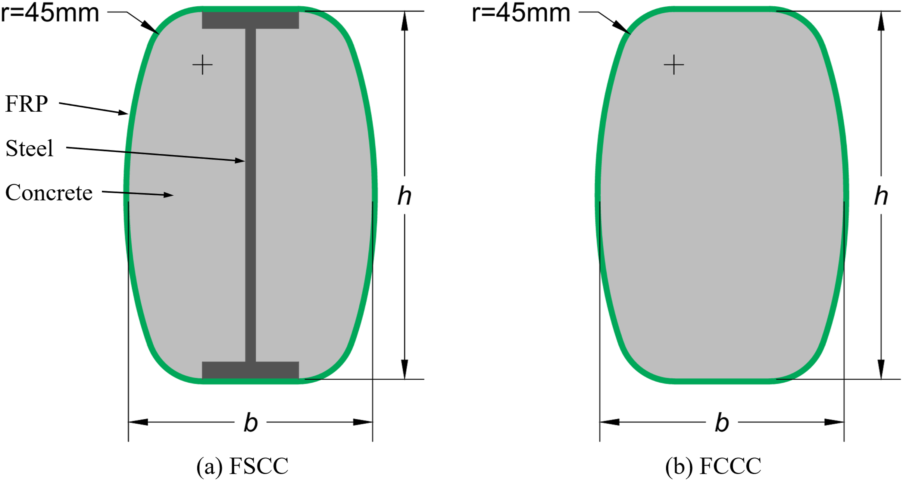
Test specimens.
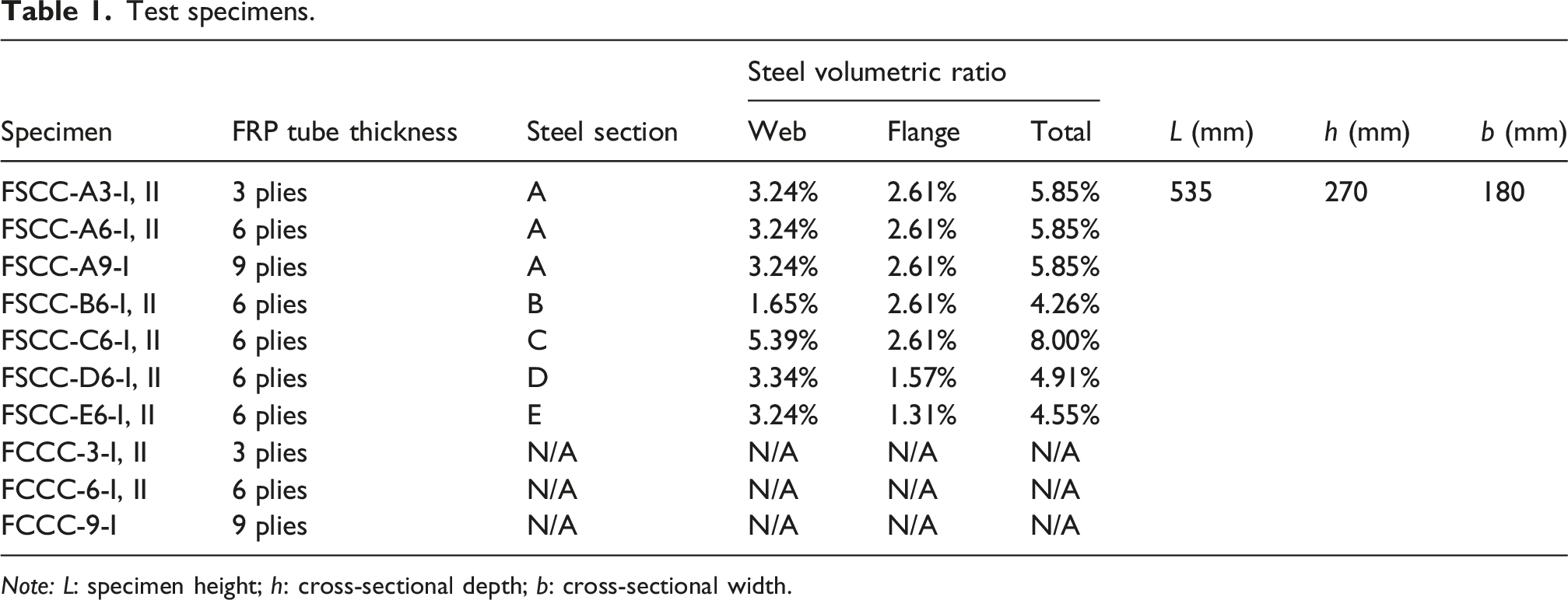
Note: L: specimen height; h: cross-sectional depth; b: cross-sectional width.
Dimensions of the steel I-sections.
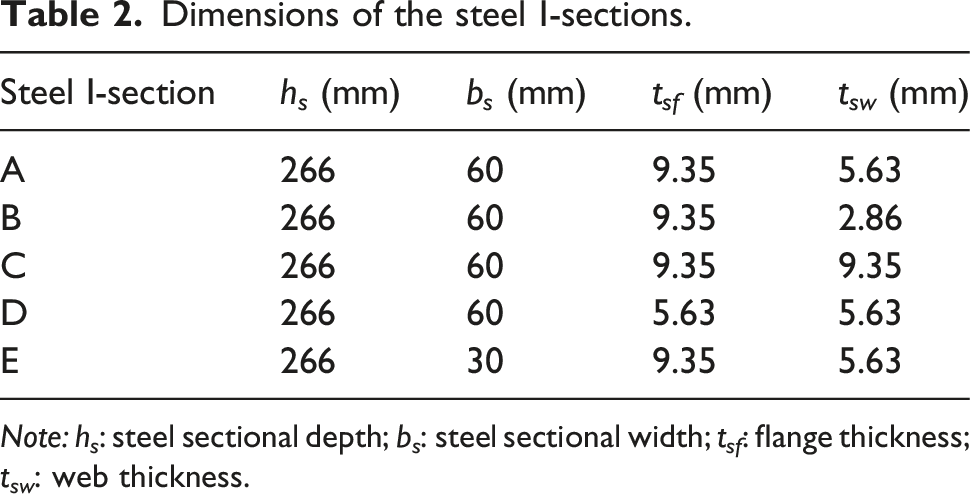
Note: h s : steel sectional depth; b s : steel sectional width; t sf : flange thickness; t sw : web thickness.
In this study, the following specimen naming convention is adopted for ease of discussion. The names of specimens begin with four letters indicating the specimen type (e.g., FSCC or FCCC), followed by a capital letter A to E (for FSCC specimens only) denoting the type of embedded steel I-sections as defined in Table 2. The following is a number (i.e., 3, 6, or 9) representing the number of FRP layers. Finally, Roman numerals I and II are adopted to differentiate the two nominally identical specimens. For example, FSCC-B6-I denotes the FSCC specimen with a steel I-section B and 6-ply FRP tube.
Material properties
Mix proportion of ready-mixed concrete.

Material properties of steel with different thicknesses.

Preparation of specimens
The FRP tubes were fabricated using the filament winding process. The cured tubes were then cut into segments of 535 mm and fixed on a wooden formwork with waterproof sealant at the bottoms, steel I-sections were then fitted into the FRP tubes and concrete was cast as shown in Figure 2. The specimens were then cured in ambient environment with proper watering for 28 days. Prior to testing, both ends of each specimen were strengthened with 3-ply 40-mm-wide CFRP strips to prevent premature end failures of specimens. Fabrication of specimens.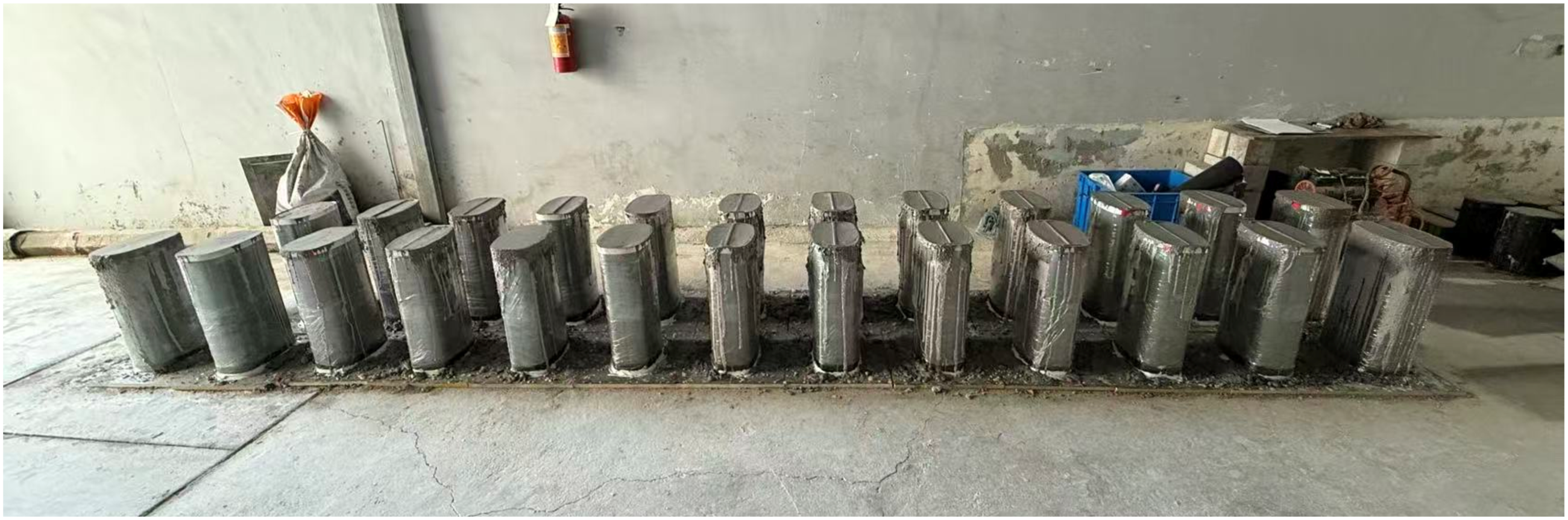
Test setup, instrumentation and loading scheme
Figure 3 illustrates the strain gauge arrangement on the test specimens. For FRP tubes, eight 20 mm strain gauges were attached in the hoop direction at the mid-height (four at the corners, two at the elliptical sides and two at the flat sides); in addition, four axial strain gauges with the same gauge length were mounted on both elliptical sides and flat sides of the FRP tubes to monitor the axial shortening. For the steel I-sections embedded in the specimens, six strain gauges of 5 mm gauge length were attached at the mid-height of the embedded steel I-sections (four axial strain gauges on the flange and web, and two lateral strain gauges on the web). Arrangement of strain gauges.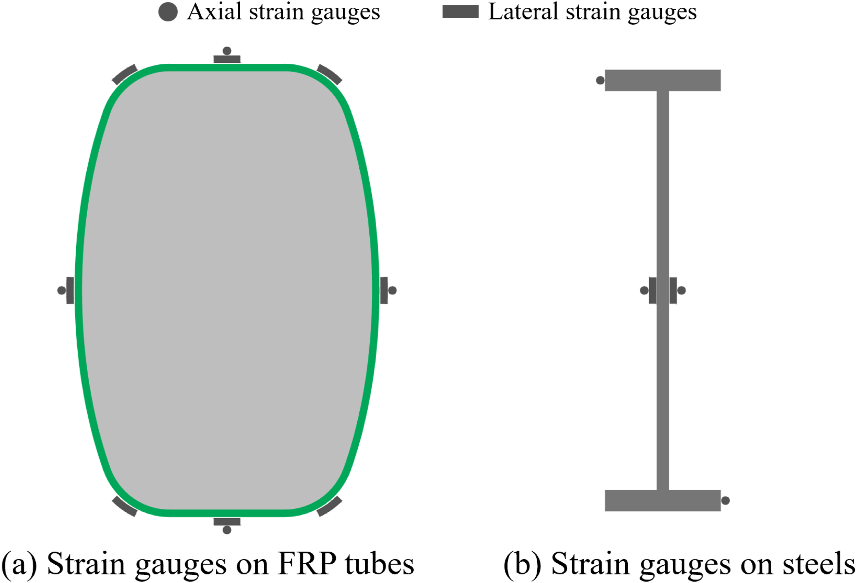
Six Linear Variable Differential Transformers (LVDTs) were employed to measure both the global and local deformations of the specimens as shown in Figure 4. Four LVDTs, denoted as LVDTs 1–4, were mounted near four corners of the specimens to capture the axial deformation over the full height of the specimens, while two additional LVDTs, denoted as m1 and m2, with a gauge length of 200 mm were attached on the specimen to monitor the local deformation of the mid-height region. Displacement control with a loading rate of 0.4 mm/min was applied during tests, this loading rate was derived from the stress rate of 0.5 MPa/s according to the standard GB/T 50081 (2019). Test setup and arrangement of LVDTs.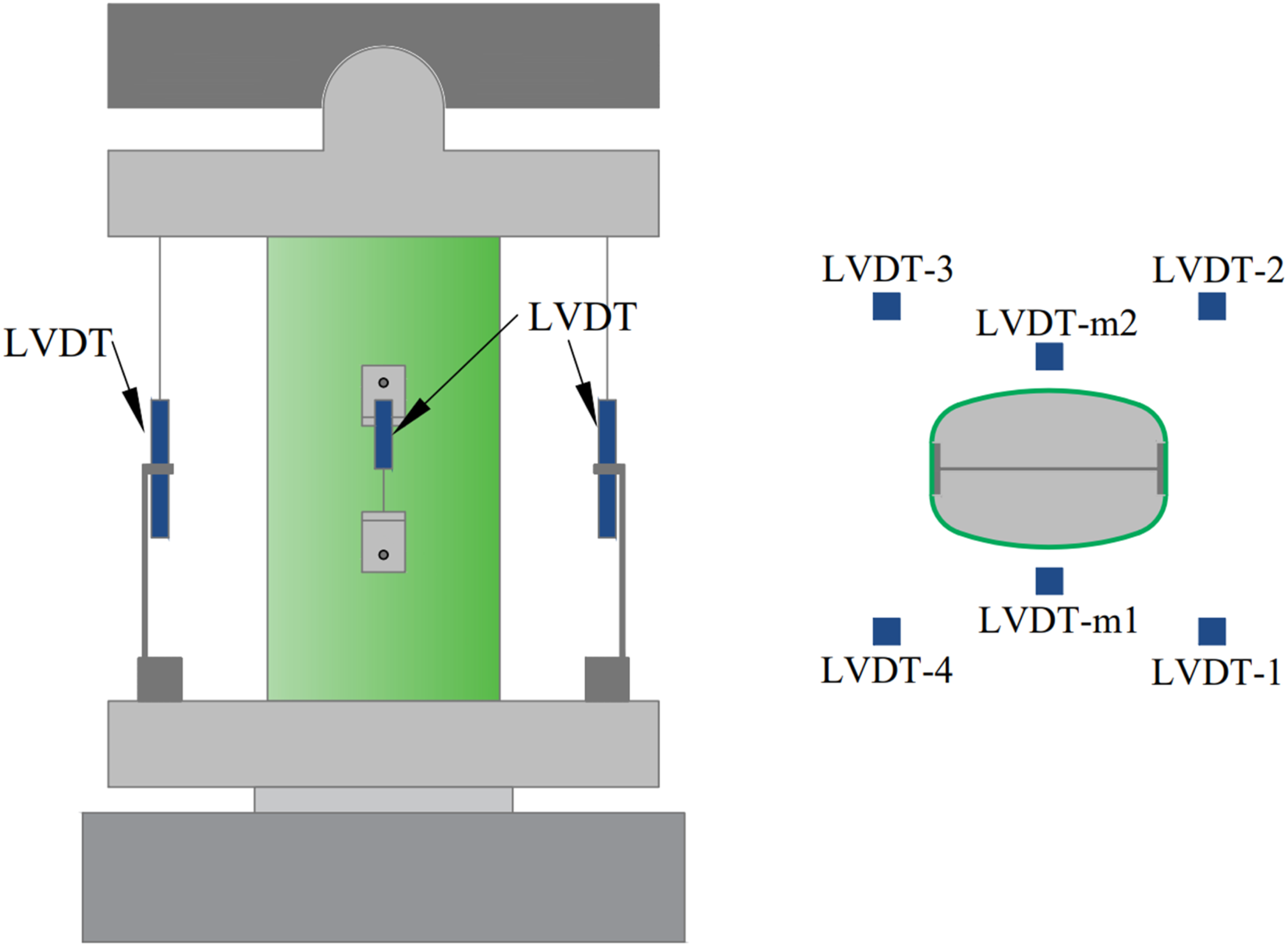
Test results and discussions
Failure modes
Figure 5 presents the typical failure modes of the FSCC and FCCC specimens. Most specimens failed by hoop rupture of FRP tube, which occurred near the corner regions around the mid height, as illustrated in Figure 5(a) and 5(b). Correspondingly, a sharp and extensive drop of axial load was observed at failure. Similar failure modes have been extensively reported in existing studies on FRP confined concrete with rectangular cross-sections (e.g., Zeng et al., 2018). It should be noted that some specimens tested in this study (marked with a superscript “*” in Table 5) experienced minor fracture of FRP tubes (see Figure 5(c)) during loading, which was generally accompanied by a slight drop of axial load as discussed later in this paper. The steel I-section embedded in FSCCs is constrained by the concrete and FRP tube, so its buckling is impossible as demonstrated by a prior study (Han et al., 2026). Consequently, in the present study, the failure mode of the steel section is not presented here. Typical failure modes of FSCCs and FCCCs.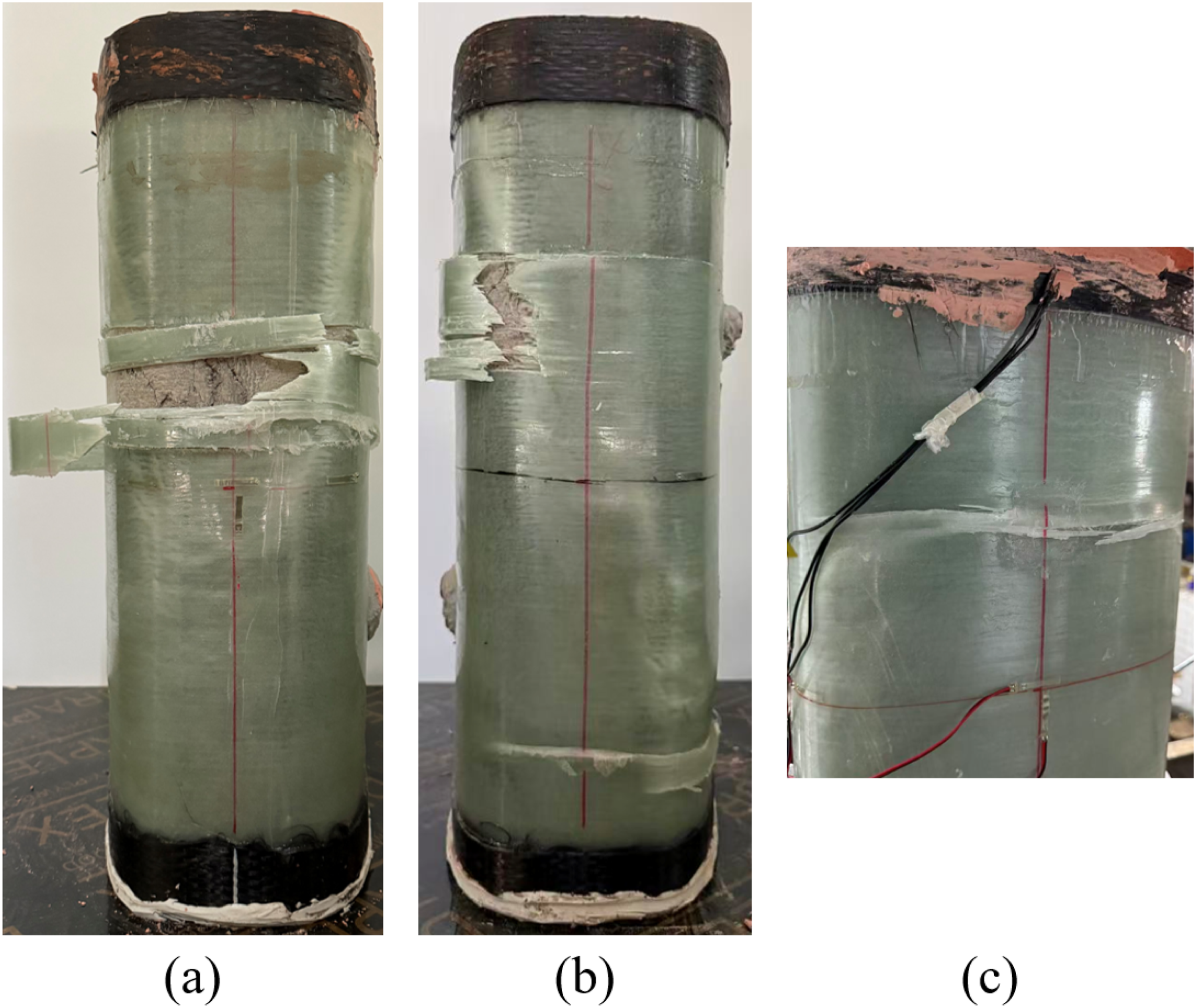
Axial load–axial strain behaviour of FCCCs
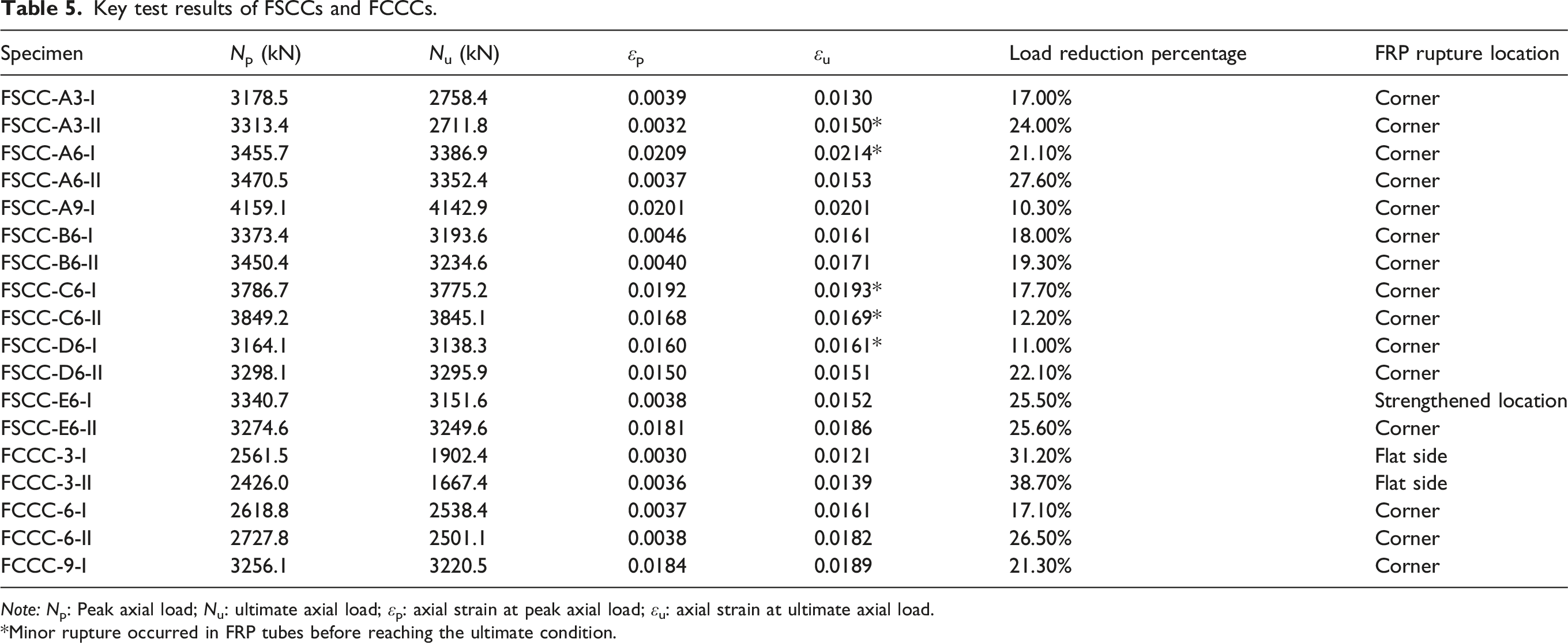
The axial load–strain relationships of the five FCCC specimens are shown in Figure 6, and Table 5 provides the test results. Specimen FCCC-9-I was unloaded when axial shortening reached 0.0148 to conduct an inspection, after which it was reloaded until failure. The unloading-reloading curve was removed from the following analysis. It should be noted that all axial strains reported in Figure 6, Table 5, and subsequent figures were obtained from the four full-height LVDTs (i.e., LVDTs 1–4 in Figure 4) for both FCCCs and FSCCs. This is because the data obtained from two LVDTs at mid-height (i.e., LVDTs m1 and m2 in Figure 4) were found to be inaccurate due to the relative axial slippage between the concrete core and the FRP tubes during loading. It should be noted that all specimens exhibited a certain degree of fluctuation in axial load. However, the load cell had been calibrated and was capable of accurately measuring the axial loads. As shown in Figure 6, all FCCC specimens exhibited an obvious load drop after approaching the first peak load at axial strains of approximately 0.30%–0.38%, with the load drop ranging from 17.1% to 38.7% of the first peak load. This load drop could be caused by the following two reasons: (1) the ready-mix concrete used in this study experienced some unexpected shrinkage due to the use of slag powder in mix design, which led to a tiny gap between the FRP tube and the concrete core before loading, and this could delay the activation of FRP confinement and lead to the load drop after the first peak load (Vincent and Ozbakkloglu, 2015); (2) compared to circular FRP tubes, the truncated elliptical FRP tubes used in this study has a relatively lower confinement efficiency for the concrete core, which could lead to a load drop after the first peak load due to lack of lateral confinement. Axial load-strain behaviour of FCCCs.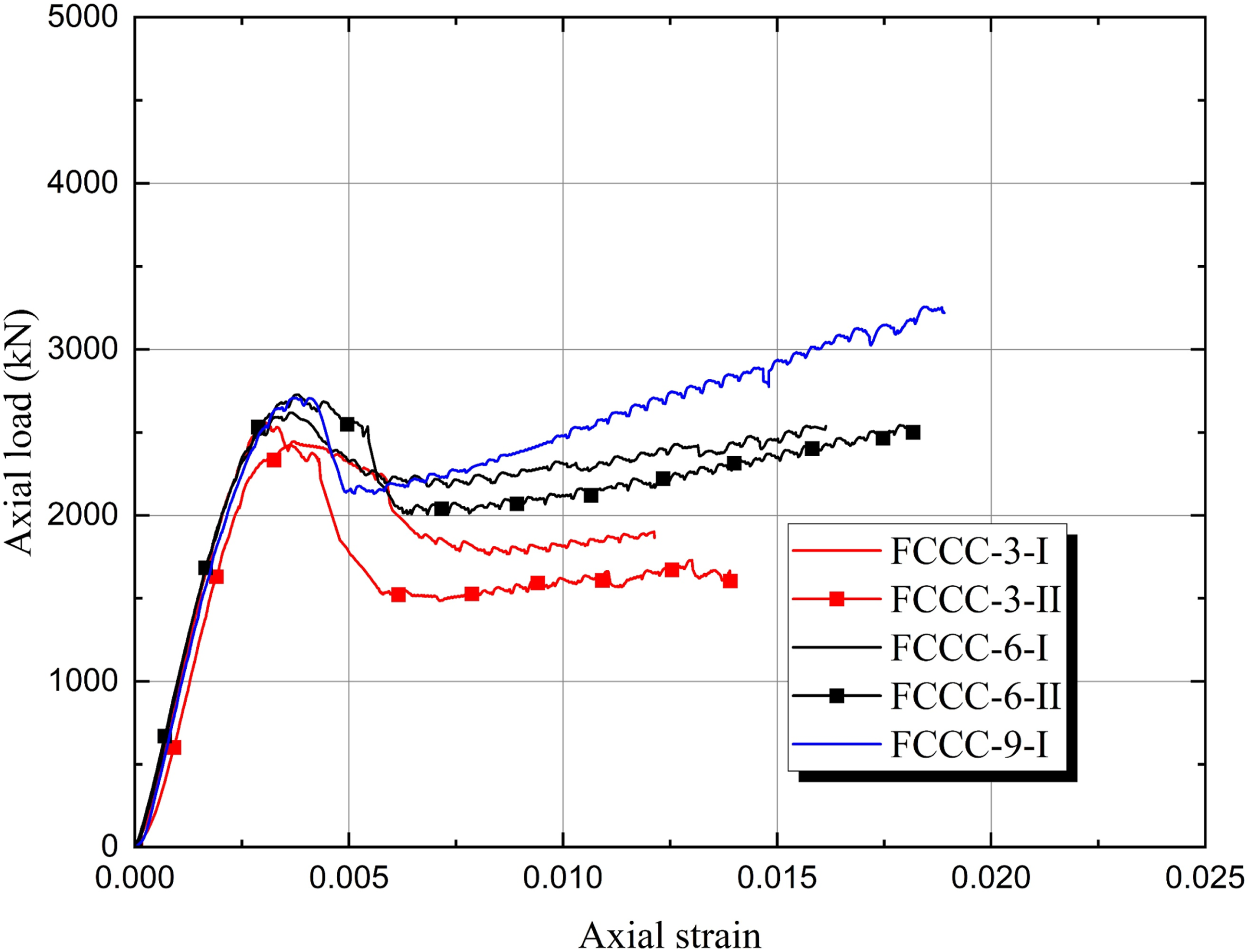
Among the specimens, FCCC-3-I and FCCC-3-II exhibited the most significant load drops, reaching 31.2% and 38.7%, respectively. In contrast, the 6-ply specimens exhibited relatively smaller load drops of 17.1% and 26.5%, while the 9-ply specimen showed a load drop of 21.3%. These observations suggest that increasing the thickness of the FRP tube enhances the confinement effect, thereby mitigating the severity of load drop. With further increase in axial strain after the load drop, the axial load of all FCCC specimens tended to increase again as shown in Figure 6. It can also be observed that, in the second ascending branches, the slope, the ultimate load, and the ultimate strain of FCCC specimens increased with increasing FRP tube thickness. This is because increasing the thickness of the FRP tube enhances the confinement stiffness provided to the concrete core. Similar observations have been widely reported in previous studies (Lam and Teng, 2003; Liu et al., 2023).
Axial load–axial strain behaviour of FSCCs
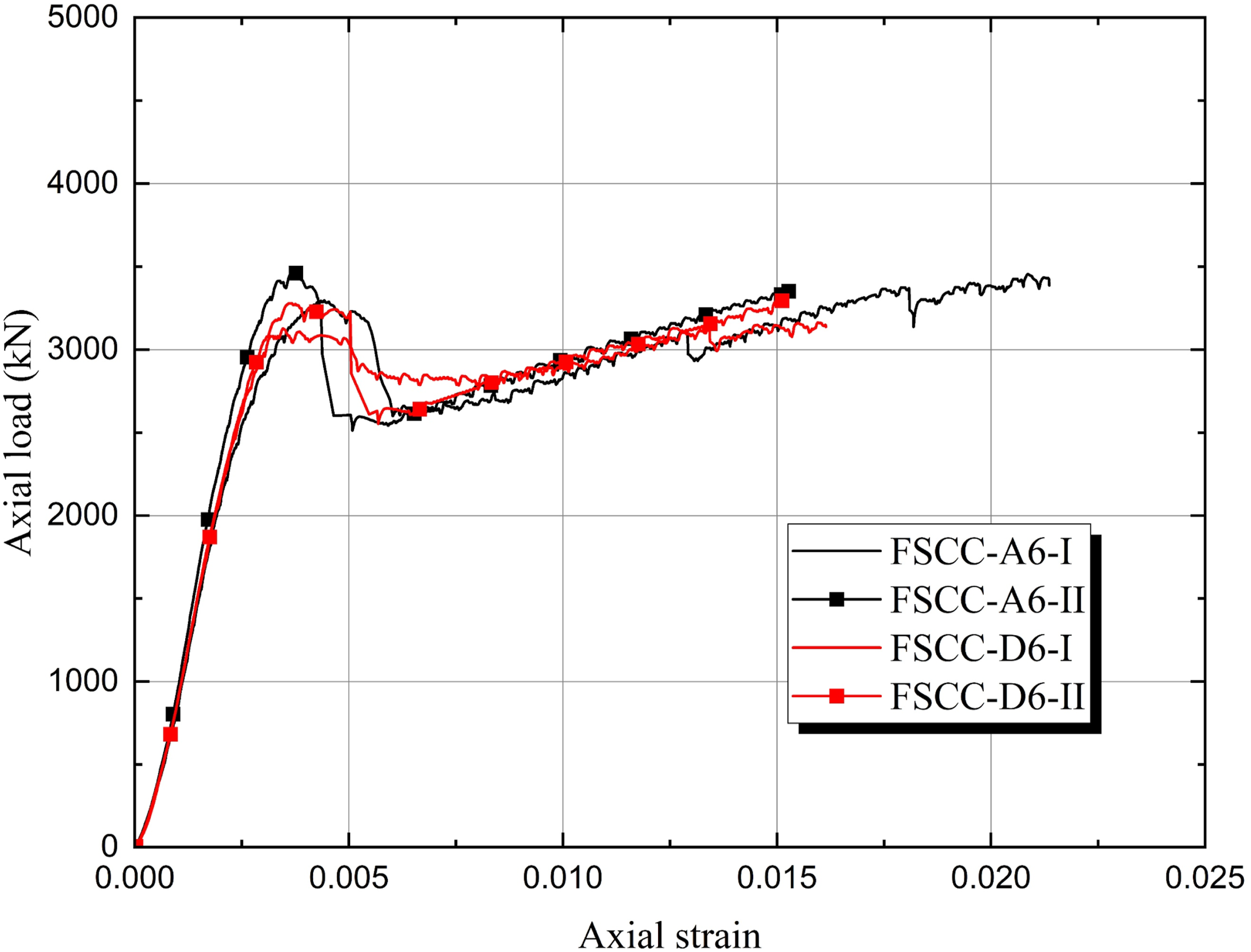
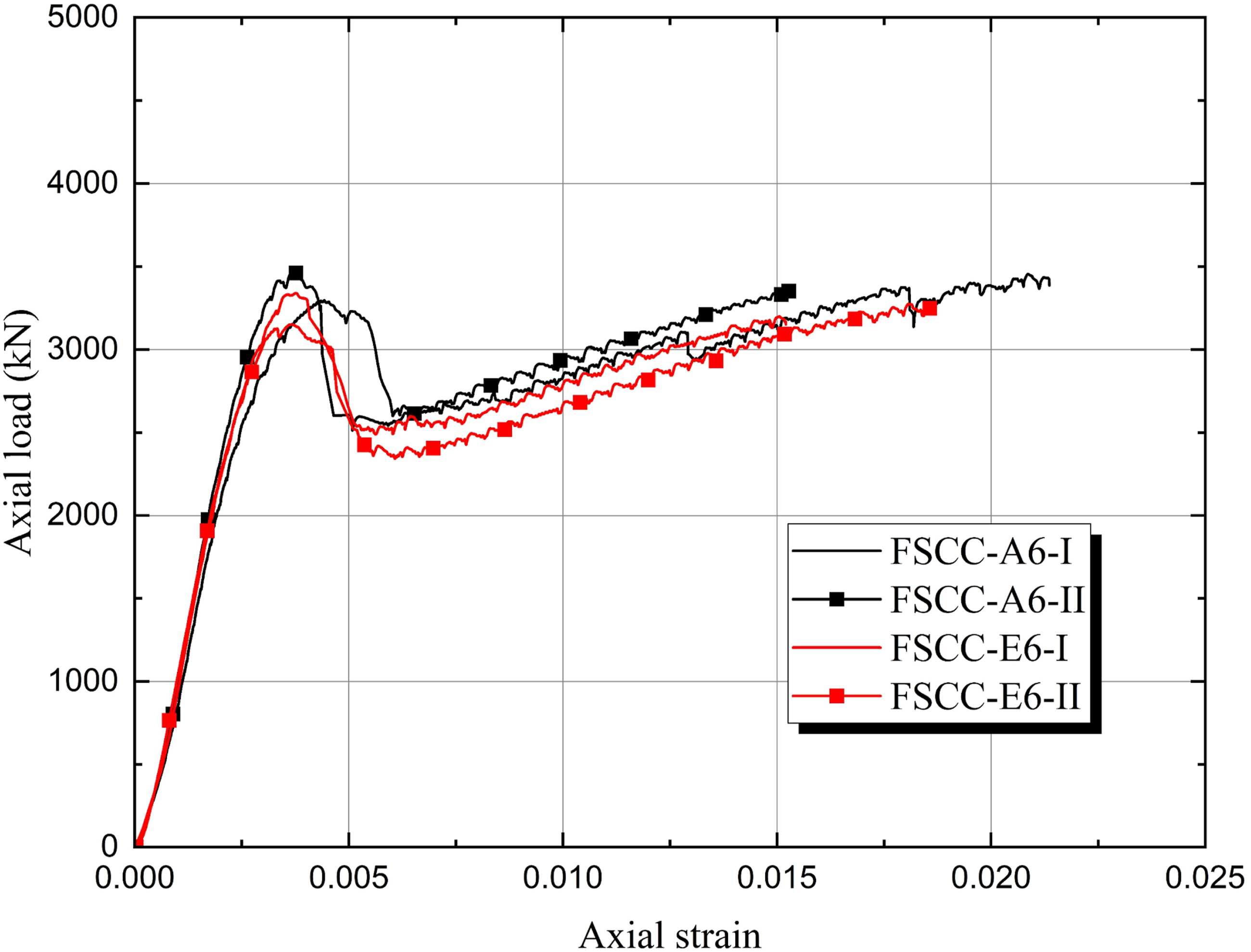
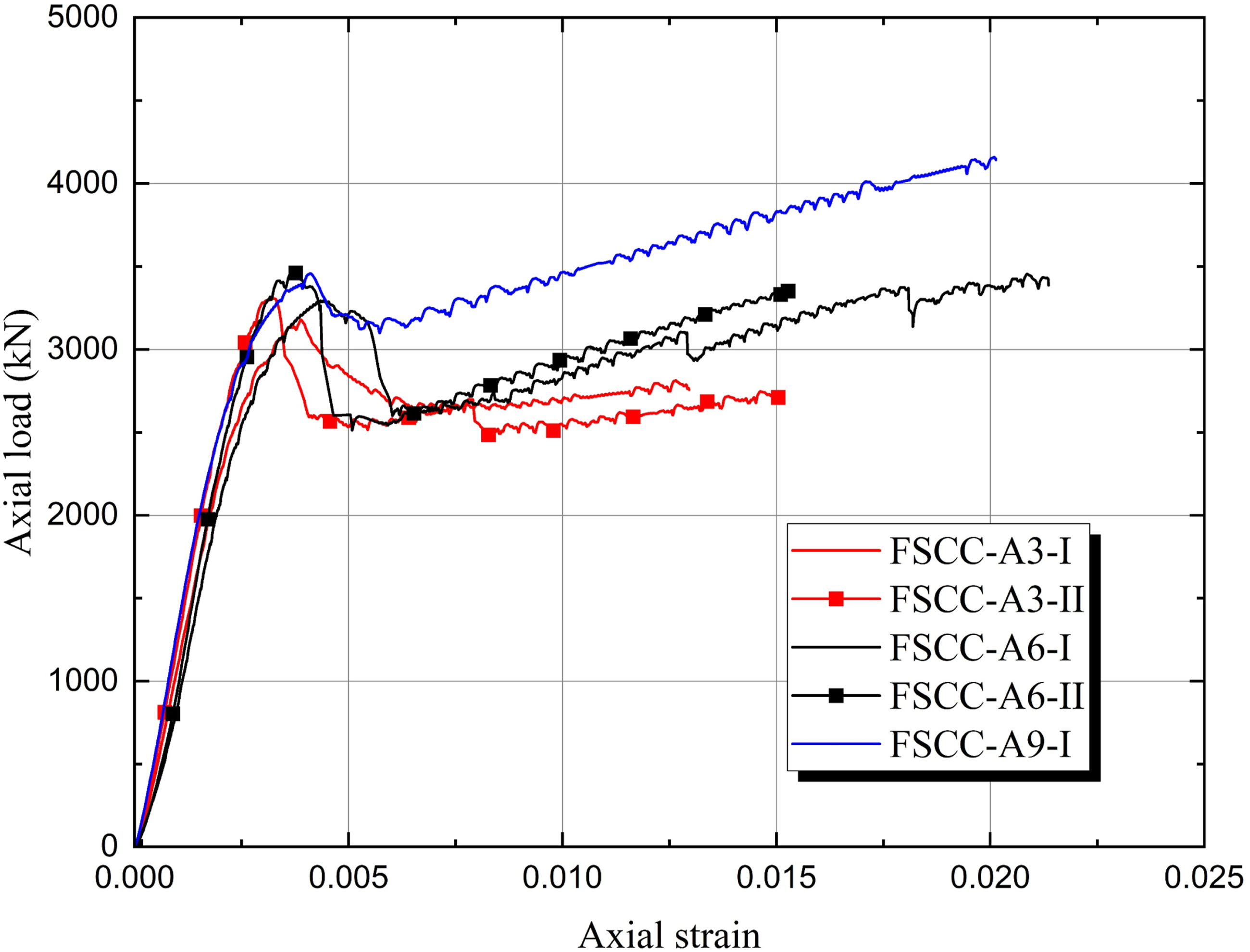
The axial load–axial strain relationships of all FSCC specimens are shown in Figures 7–10, and Table 5 provides the summary of the key test values. To facilitate the evaluation of the parameter influences on the axial load–strain behaviour, the curves are grouped and discussed according to the test parameters (i.e., FRP tube thickness and steel I-section dimensions). It is observed that all FSCC specimens exhibited a certain degree of load drop (10.3%–27.6%) after approaching the first peak load (at axial strains of approximately 0.32%–0.46%), similar to that of FCCC specimens. The dropping ratios were slightly smaller but the dropping values were roughly the same, since the first peak load of FSCC was higher than that of the corresponding FCCC. This behaviour differs from that reported in the previous study (Han et al., 2026), where FSCC specimens with low-strength concrete typically show a bilinear axial load–strain response without noticeable load drop, while those with high-strength concrete show a gradual load drop followed by a recovery of axial load. As discussed in the previous section, this is again likely related to the shrinkage of concrete and employing noncircular FRP tube. After the load drop, as shown in the figures, all FSCC specimens exhibited ductile behaviour with increasing axial shortening until failure occurred due to FRP rupture in hoop direction. It is worth noting that the concrete used in this study had a compressive strength of 59.1 MPa, which was somewhat between normal-strength concrete and high-strength concrete. Thus, the conclusions of this study may be carefully checked when the compressive strength is remarkable different (e.g., lower than 40 MPa or higher than 80 MPa). Effect of web thickness on axial load-strain behaviour of FSCCs. Effect of flange thickness on axial load-strain behaviour of FSCCs. Effect of flange width on axial load-strain behaviour of FSCCs. Effect of FRP thickness on axial load-strain behaviour of FSCCs. Key test results of FSCCs and FCCCs. Note: Np: Peak axial load; Nu: ultimate axial load; εp: axial strain at peak axial load; εu: axial strain at ultimate axial load. *Minor rupture occurred in FRP tubes before reaching the ultimate condition.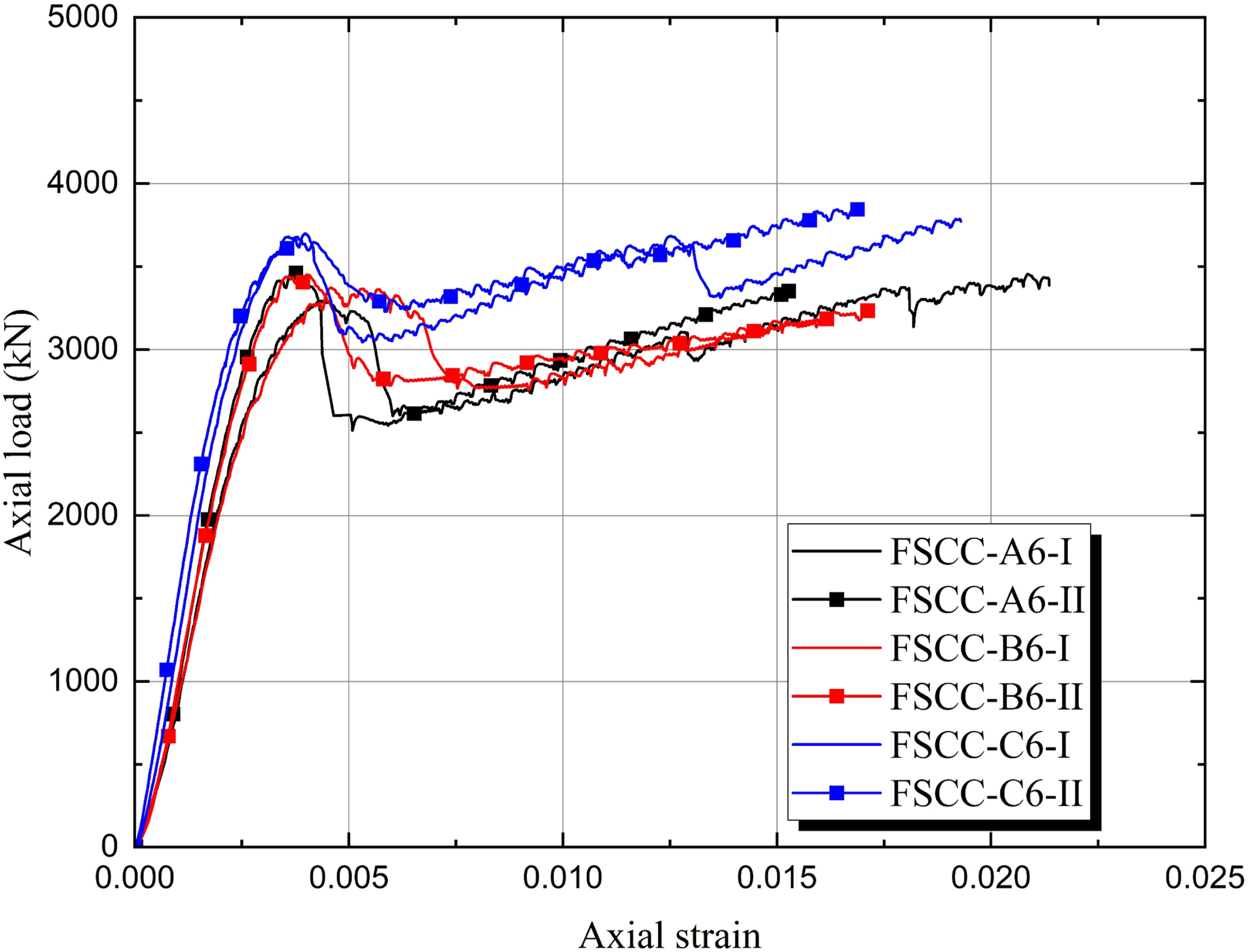
Effect of web thickness
Figure 7 illustrates the influence of web thickness on the relationships of axial load–strain. It is shown that the curves of FSCC-A6-I and FSCC-C6-I exhibited a slight drop in the second branch at axial strains of approximately 0.0129 and 0.0181, respectively. This is because at these axial strains, both FSCC-A6-I and FSCC-C6-I experienced a minor localized FRP rupture which resulted in a slight reduction of lateral confinement provided by the FRP tubes. Nevertheless, it is observed that the minor localized FRP rupture also led to a minor localized axial deformation in the rupture region, resulting in slightly larger ultimate axial strains of these specimens as shown in Figure 7. Therefore, for accuracy of comparisons, only the axial load–strain relationships of specimens with no local FRP damage are considered in later discussions.
As shown in Figure 7, the increase of web thickness results in a higher and steeper first ascending branch (prior to the load drop) and a higher second ascending branch (after the load drop) of the axial load–strain relationships. In the initial loading stage, the lateral confinement from the FRP tubes and steel I-sections has not been activated, thus the higher and steeper initial ascending branch is attributed to only the higher steel volume ratio caused by the increase of web thickness. Whereas for the second ascending branches, increasing web thickness results in only higher curves, but causes minor effect on the slope and ultimate strain of the axial load–strain relationships (e.g., for specimens FSCC-A6-II, FSCC-B6-I and FSCC-C6-II). This is because in the second ascending branches: (1) the yielded steel web acting in axial compression and lateral tension provided only marginal lateral confinement compared to the FRP tube; (2) the slope of the curve mainly depends on the stiffness of lateral confinement, roughly the lateral FRP confinement, which is the same for all the specimens; (3) the higher curve is mainly due to the use of larger web thickness, which leads to a larger cross-sectional area of steel I-section that carries a higher axial load; (4) the ultimate strain of the curve mainly depend on the FRP rupture strain, which is the same for all the specimens.
Effect of flange thickness
Figure 8 shows the influence of flange thickness on the axial load–axial strain responses of FSCCs. The results indicate that in the variation of flange thickness considered in this study plays only a minor role in affecting the axial stress–strain behaviour of FSCCs. The reasons include (1) All the specimens in Figure 8 have the same FRP tube thickness, thus FRP confinement is roughly the same for all the specimens; (2) the lateral confinement provided by steel I-section, which is mainly governed by web thickness, is marginally affected by the thickness of flange; (3) the relatively small variation of flange thickness considered in this study has marginal effect on the cross-sectional area of the steel I-section and thus the axial load carried by the steel I-section.
Effect of flange width
Figure 9 illustrates the effect of the width of flange on the axial load–strain responses of FSCCs. Similar to the observations in Figure 8, Figure 9 shows that the changing of flange width considered in this study only slightly affects the height of the curves. This is mainly due to the variation of axial load directly carried by the steel I-section, which is caused by the variation of flange width. In addition, existing studies (Huang et al., 2021, 2023) have shown that when the flange width is larger than a small threshold, further increase of flange width exhibit minor effect on the confinement effect of the steel I-section.
Effect of FRP tube thickness
The influence of FRP thickness on the axial load–strain relationships of FSCCs is illustrated in Figure 10. It shows that the variation of FRP tube thickness mainly affects the second ascending branches (after the load drop) of the curves, and it is clearly seen that increasing FRP tube thickness results in a longer and steeper second ascending branch. The mechanism behind has reported in many existing studies: (1) a thicker FRP tube provides a higher confining stiffness, leading to a higher slope of the curves; (2) for the same axial strain, a thicker FRP tube leads to a smaller hoop strain of FRP due to its larger confining stiffness, and thus at the same hoop rupture strain of FRP, a thicker FRP tube results in a higher ultimate axial deformation (Lam and Teng, 2003).
Comparisons of FSCCs and FCCCs
The axial load-axial strain curves of FSCCs and FCCCs are compared in Figure 11. It is clearly shown that with the same FRP tube thickness, FSCC specimens have higher initial stiffness and first peak loads than the corresponding FCCC specimens due to the embedded steel I-sections in the former. The difference in the first peak loads between the FSCC and FCCC specimens was approximately 735 kN, which is close to the axial load carried by the corresponding steel I-sections (765 kN) alone. Comparation of axial load-strain behaviour of FSCCs and FCCCs.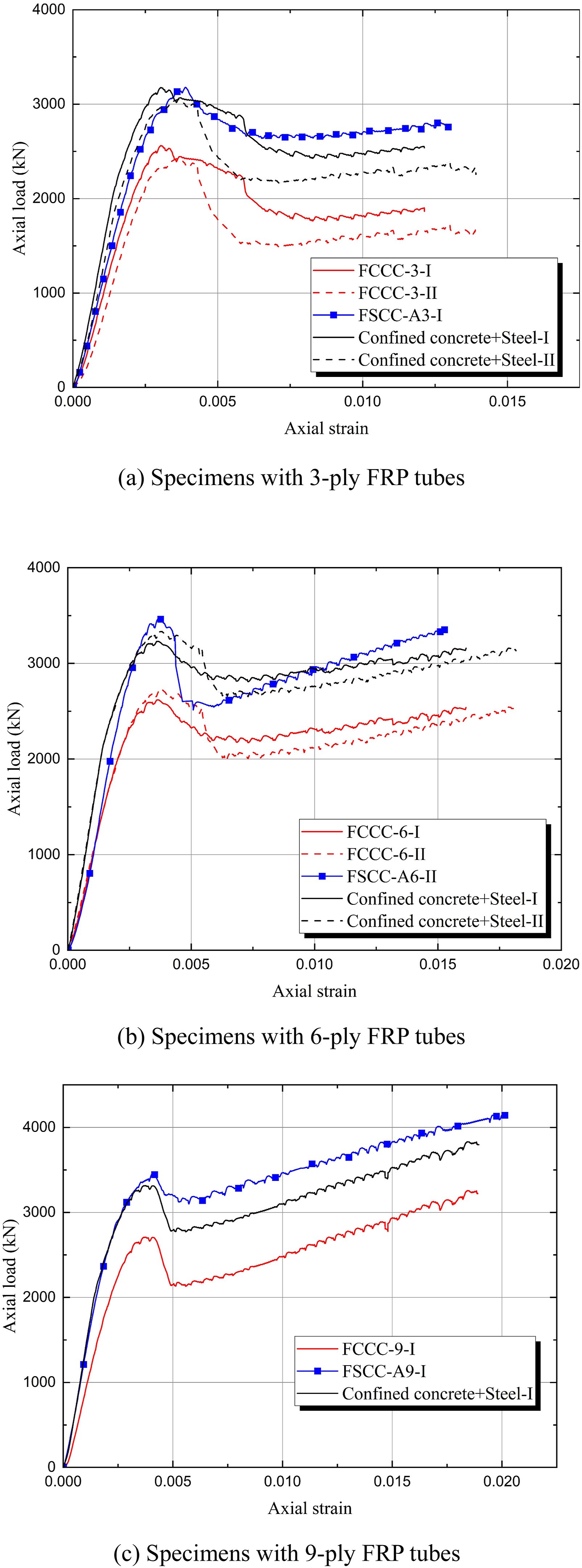
Notably, the FSCC specimens also generally exhibit smaller load drops compared with the corresponding FCCC specimens. The reason is believed to be that when the load drops happened, the steel I-section provided some lateral confinement for the concrete in FSCCs, which somewhat mitigated the load drops. It can be seen from Figure 11 that there is no significant difference between the second-branch stiffness of the curves of FSCCs and FCCCs except for some difference between the comparisons of specimens with 6-layer FRP tubes. This is because in the second branch, the steel I-sections in FSCCs are generally in yield state and its confinement for the concrete tends to be constant, therefore the confinement stiffness, which determines the stiffness of the second branch of the curves, mainly determined by the confining stiffness of the FRP tube.
The summation axial load–axial strain curves of confined concrete and steel I-section are also compared with the axial load–axial strain relationships of FSCCs in Figure 11. The data for confined concrete in the summation curve are taken from the test results of FCCCs, while the data for the steel I-section in the summation curve are obtained from the test results of steel coupons. The contribution of FRP tube is not considered in the summation curve as the axial load carried by the FRP tube is believed to be negligible. It can be observed that, regardless of the thickness of the FRP tube, the FSCCs exhibit higher axial loads in the post-yielding stage compared to the corresponding summation curve, confirming the dual confinement effect of FRP and steel I-sections in FSCCs.
Behaviour of FRP tubes of FSCCs and FCCCs
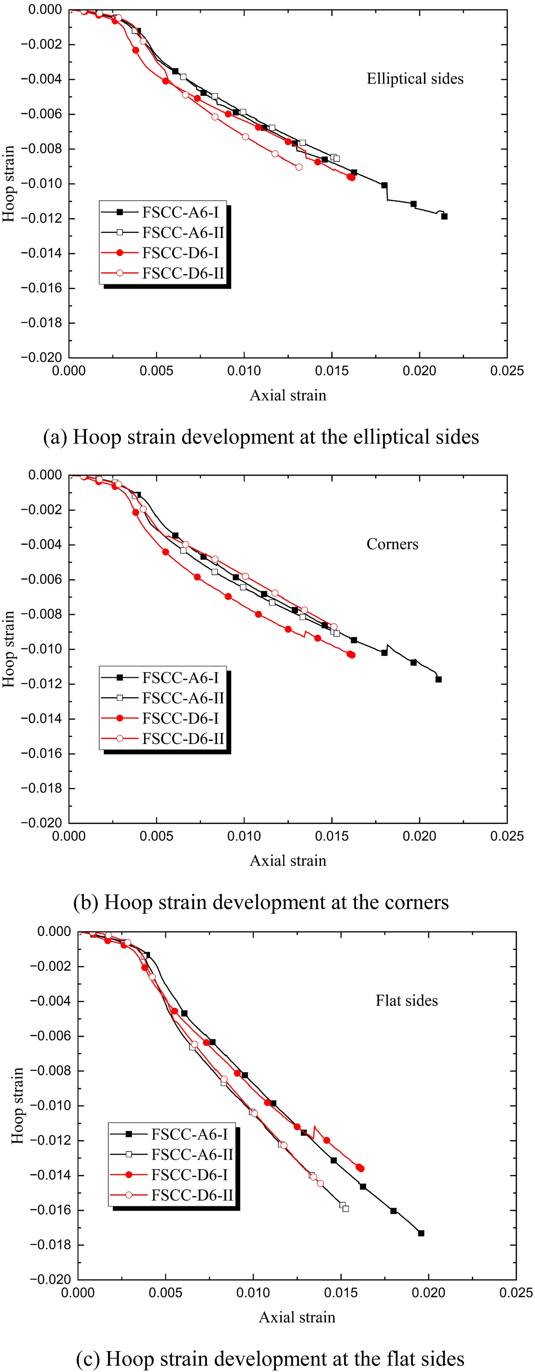
Figures 12–15 show the effects of various test parameters on the hoop strain–axial strain relationships of the FRP tubes of FSCC specimens. In these figures, the axial strains are derived from the total axial deformation of each specimen, whereas the hoop strains come from hoop strains measured at the mid-height of the FRP tubes by strain gauges. For the elliptical and flat sides, the hoop strains represent the mean of valid readings from two opposite sides; for the corners, it is the mean of valid readings from four corner strain gauges. Effect of web thickness on FRP hoop strain of FSCCs. Effect of flange thickness on FRP hoop strain of FSCCs. Effect of flange width on FRP hoop strain of FSCCs. Effect of FRP thickness on FRP hoop strain of FSCCs.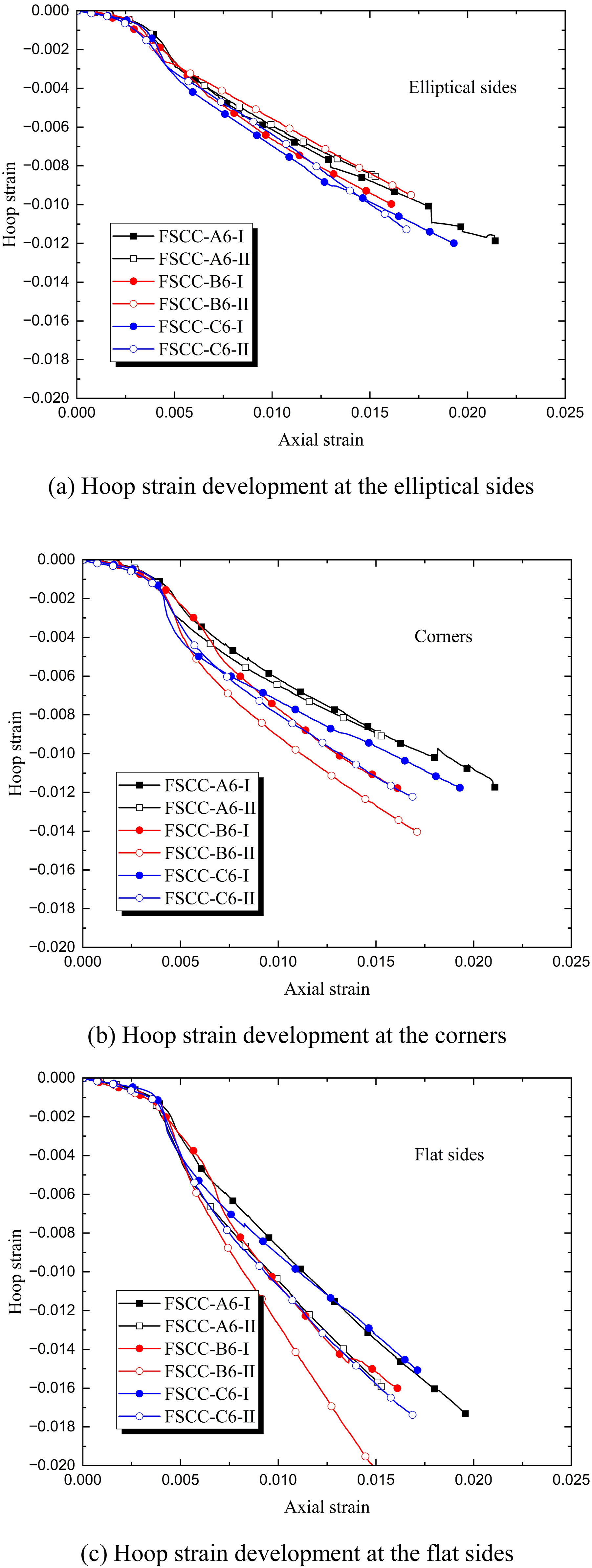
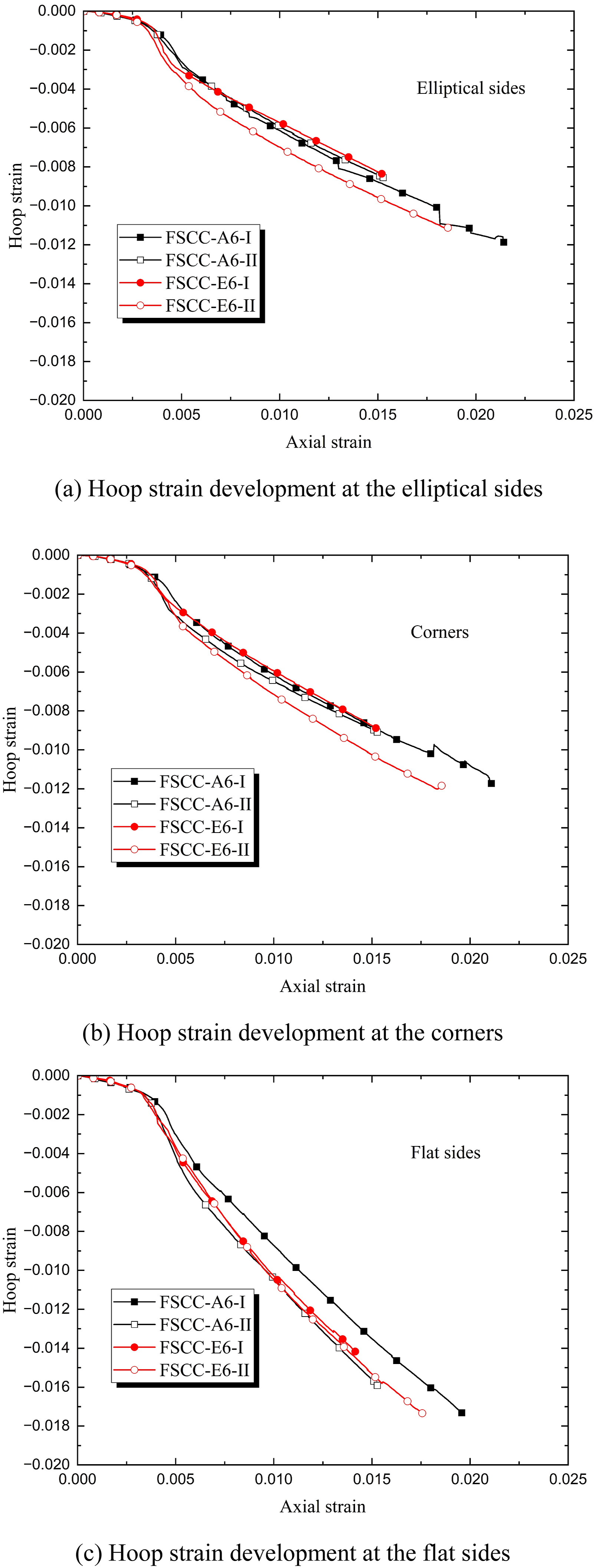
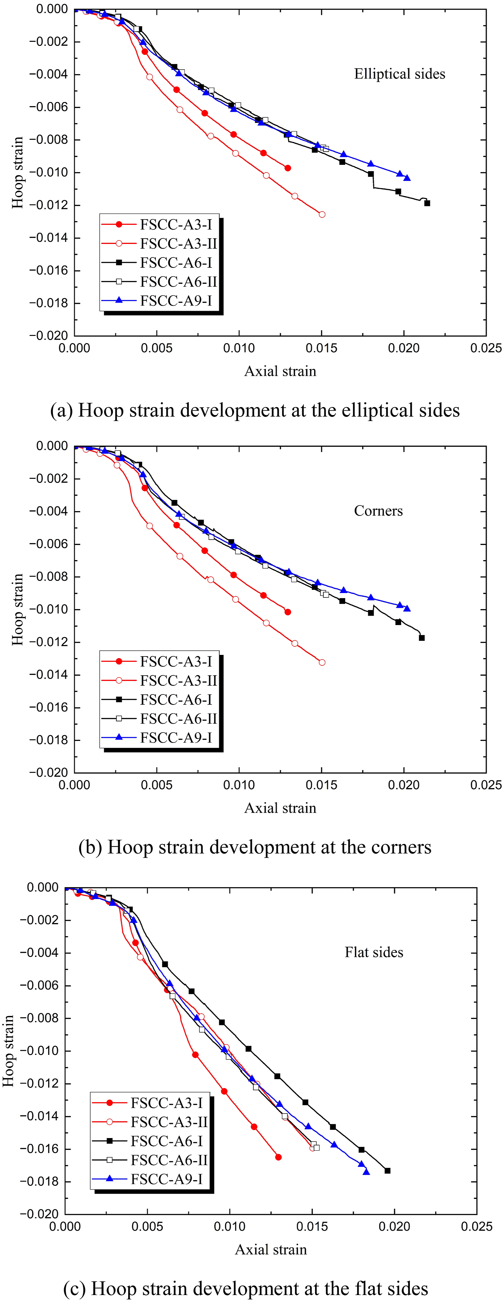
In the elastic stage, the hoop strains at different locations increase gradually with axial strain for all specimens. Upon reaching the first peak load of the axial load–axial strain curve (e.g., at the axial stain of around 0.35%), the FRP tube was triggered by lateral expansion of concrete and began to provide lateral confinement, which leads to a faster increase in hoop strains thereafter.
Effect of web thickness
Figure 12 illustrates the influence of web thickness on the hoop strain development of the FRP tube in FSCCs. The steel web thickness of Section A, B and C was 5.63 mm, 2.86 mm and 9.35 mm, respectively. It can be observed that variations in web thickness have only marginal effects on the hoop strains at the middle of elliptical sides, but pronounced effects on those at the corners and flat sides. This is because the confinement of steel I-section mainly affects the concrete in the regions near the two flange-web intersections (Huang et al., 2023), and these regions are close to the flat sides and the corners but far away from the middle of elliptical sides. It is shown from Figure 12 that the increase of web thickness leads to a smaller FRP hoop strains at corners and flat sides. This is because increasing web thickness tends to increase the lateral confinement provided by steel I-section. The concrete near the corners and flat sides is thus better confined, leading to smaller lateral expansion and thus smaller hoop strains of FRP therein. This observation is further supported by the comparison of hoop strain responses between 6-ply FSCCs and FCCCs shown in Figure 17, which will be discussed later on.
Effect of flange thickness
Figure 13 presents the influence of flange thickness on the hoop strains of FRP tubes in FSCCs. The flange thickness of Section A and D is 9.35 mm and 5.63 mm. Figure 13 shows that this variation of flange thickness has no remarkable effect (the effect can be smaller than the scatter of data) on the FRP hoop strains at the elliptical side, the flat sides and the corners. This is because (1) the hoop strains of FRP at the elliptical sides is hardly affected by the steel I-section as discussed earlier and (2) the lateral confinement from the steel I-section is hardly affected by the variation of flange thickness considered in the current study, and thus the lateral expansion and the hoop strains of FRP is hardly affected.
Effect of flange width
Figure 14 shows how varying the flange width influences the hoop strain development of FRP tubes in FSCCs. The flange width of steel Section A and E is 60 mm and 30 mm, respectively. Similar to the case of flange thickness, the effect of the flange width on the hoop strains of FRP tube is not evident. This is because the variation of flange width considered in the current study hardly affects the lateral confinement provided by the steel I-section, and thus hardly affects the lateral expansion of concrete near the corners and the flat sides and the hoop strains of FRP there. In addition, the FRP hoop strains at the middle of elliptical sides remain insensitive to variations in flange width for the same reason discussed earlier.
Effect of FRP tube thickness
Figure 15 shows the influence of FRP thickness on the hoop strains of FRP tubes in FSCCs. The only difference among five specimens in this figure is the thickness of FRP tube. It can be observed that for a given axial strain, increasing FRP thickness generally results in smaller hoop strains of FRP tube at the elliptical sides, the flat sides and the corners. This is because for the FSCC specimens tested in this study, the lateral confinement from the FRP tube is dominant. At the same axial strain, a thicker FRP tube provides a stronger lateral confinement which leads to a smaller expansion of concrete and smaller hoop strain of FRP tube. Similar observations have reported in many existing relevant studies (Yu et al., 2010a).
Effect of embedment of steel I-sections
The typical hoop strain distributions of FRP tubes in FSCC and FCCC specimens are illustrated in Figure 16(a) and 16(b), respectively. As can be clearly seen in the figure, once the axial strain exceeds the strain at the first peak load (i.e., at the axial strain around 0.35%), the hoop strains on the flat sides of FRP tend to be obviously higher than those at the elliptical sides and the corners. The rapid development of hoop strains at the flat sides, particularly in the FCCC specimens, can be attributed to the lateral expansion of the concrete toward these regions. Due to the relatively low out-of-plane stiffness of the flat sides, the FRP tube tends to undergo outward bending deformation at the initial loading stage, resulting in a relatively low confinement efficiency. With continued loading, the deformation behaviour of the flat sides gradually shifts from bending toward a membrane tension state, leading to the progressive mobilization of confinement provided by the flat sides (Zhu et al., 2020). For the FSCC specimens, the embedded steel I-section provides additional restraint against the lateral dilation of concrete toward the flat sides. However, while this confinement mitigates the outward deformation of the concrete core, within the investigated range, it does not fully eliminate the trend; consequently, the largest hoop strains still occur in these regions. Distribution of FRP hoop strain in FCCCs and FSCCs.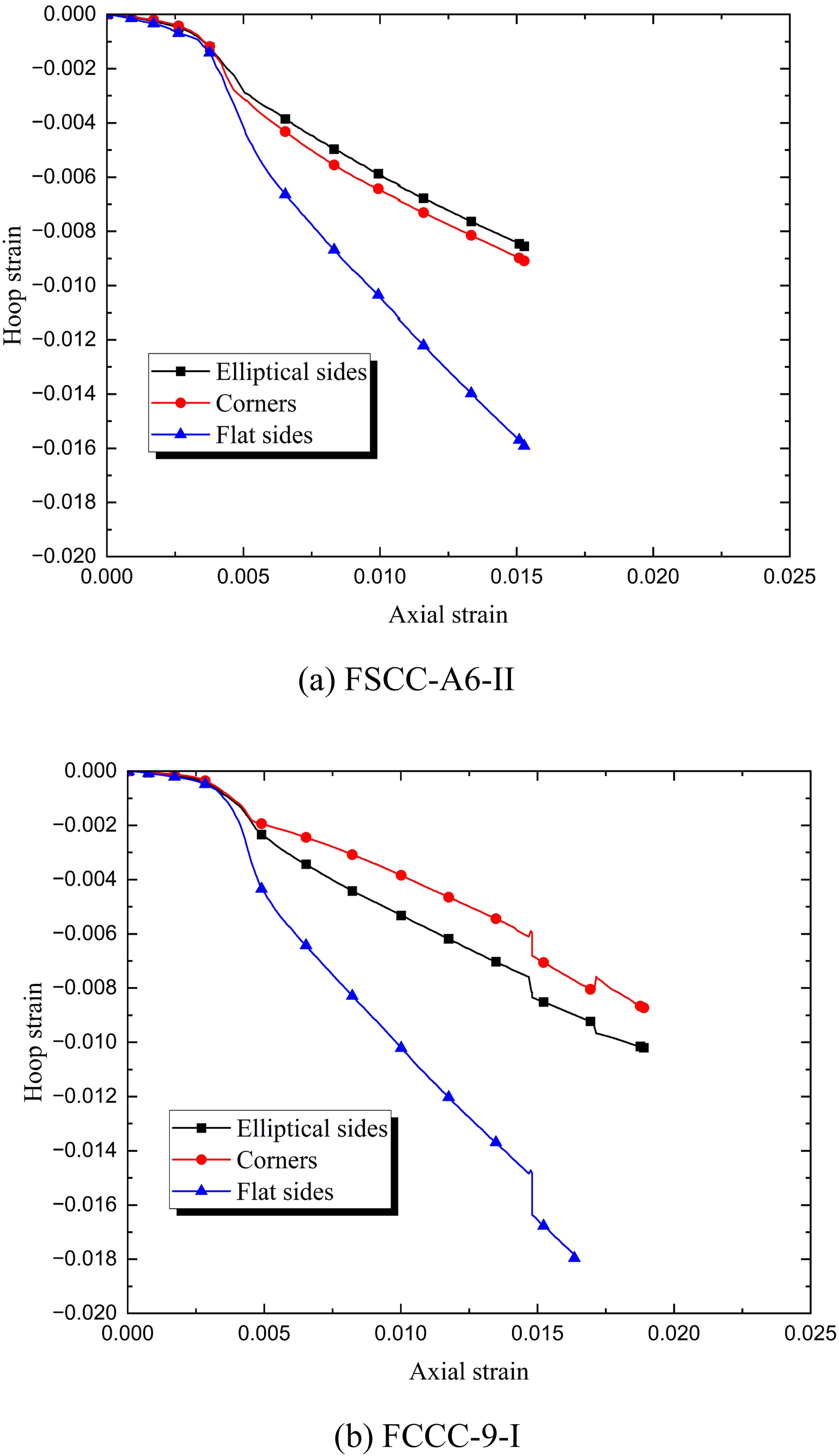
Figure 17 further compares the hoop strains of FSCC and FCCC specimens with identical FRP thicknesses. Due to the lack of valid strain data for most FCCC specimens with 3-layer and 6-layer FRP tubes, only the hoop strains at corners and flat sides of one FCCC specimen with 6-ply FRP tube (i.e., FCCC-6-II) and strains on three locations of FCCC specimens with 9-ply FRP tubes (i.e., FCCC-9-I) are selected for comparison with the corresponding FSCC specimens. Figure 17(a) and 17(b) present comparisons for specimens with 6-ply FRP tubes, while Figure 17(c)–(e) present that of specimens with 9-ply FRP tubes. Note that the slight fluctuation in the hoop strain observed in Figure 17(e) at an axial strain of 0.0148 is caused by the unloading-reloading process, however, this does not affect the relevant conclusions of the current study. Effect of embedment of steel I-sections on FRP hoop strain of FSCCs.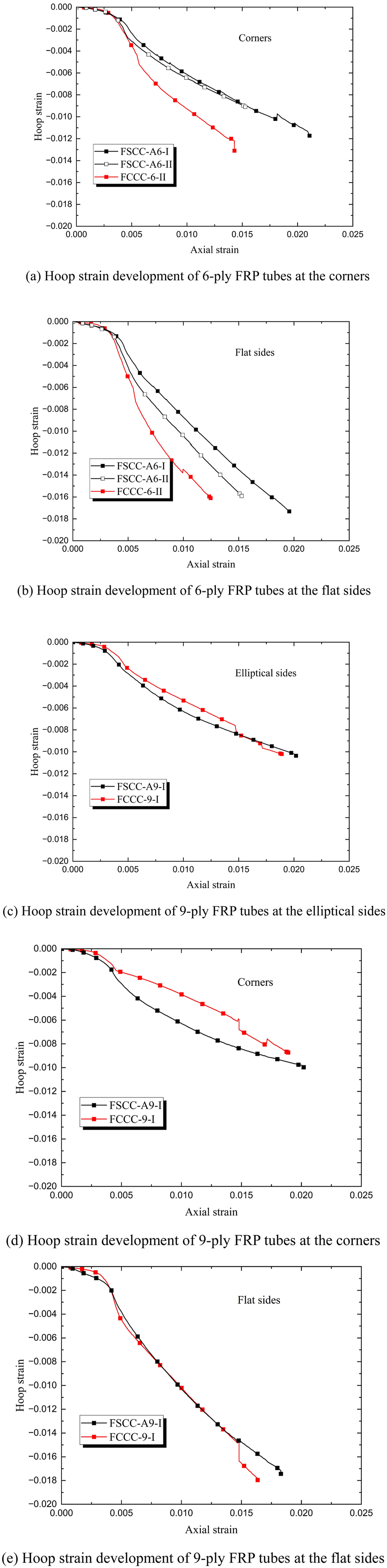
As shown in Figure 17(a) and 17(b), the incorporation of steel I-sections in FCCC specimens can effectively reduce the hoop strains at the corners and flat sides of specimens with 6-ply FRP tubes. This is not difficult to understand as the steel I-section in FSCC specimen provides additional confinement especially for the concrete near the flat sides and corner regions as discussed in previous sections. However, when 9-ply FRP tubes were used, the hoop strain responses at all three locations in FSCC and FCCC specimens become nearly identical (Although there is slight divergence in hoop strain at corners occur during loading, the divergence disappears at the ultimate condition). This indicates that when relatively thick FRP tubes (i.e., with high confinement ratio) are employed, the contribution of the steel I-sections to the lateral confinement becomes less pronounced since the confinement from FRP tube is much more significant.
Conclusions
This paper presents an experimental investigation on the compressive behaviour of a novel type of FSCM recently proposed at The Hong Kong Polytechnic University. The proposed FSCM includes a truncated FRP outer tube and a steel-encased concrete infill, of which the truncated cross-sectional shape makes it suitable for columns and beams (coupling beams). In this study, a total of 18 specimens were fabricated and tested under axial compression, with the FRP thickness and the cross-sectional dimensions of steel I-sections as key test parameters. The experimental results and discussions lead to the following conclusions: (1) The combination of embedded steel I-sections and truncated elliptical FRP tubes provides effective confinement to the concrete infill, thereby enhancing both the strength and ductility of the FSCCs. (2) Increasing the FRP tube thickness significantly enhances the load-carrying capacity and ductility of the FSCCs, while reducing the load drop after the first peak load. (3) The additional confinement provided by the steel I-section can increase the axial strength of the confined concrete in the post-yielding stage, but it has a limit effect on the slope of the second branch of the axial stress-strain relationships because the steel web is in yield state and its confinement for the concrete tends to be constant. (4) Within the investigated range, variations in the web and flange dimensions of the steel I-section have a relatively limited effect on the axial load–strain response and the overall structural performance of FSCCs. (5) The hoop strain distribution in the FRP tubes of FSCCs is highly non-uniform, with the largest hoop strain occurring at the flat sides. The embedded steel I-sections provide additional restraint against the lateral dilation of concrete, thereby influencing the hoop strain distribution in the FRP tubes; however, this effect becomes less significant in specimens with thicker FRP tubes.
Footnotes

Author Contributions
Dong Han: Investigation, Data curation, Writing – original draft.
Le Huang: Supervision, Methodology, Validation, Writing – review and editing.
Tao Yu: Conceptualization, Methodology, Supervision, Validation, Writing – review and editing, Funding acquisition.
Funding
The authors disclosed receipt of the following financial support for the research, authorship, and/or publication of this article: The authors are grateful for the financial support received from the Research Grants Council of the Hong Kong Special Administrative Region (Project No. 15222321) and the State Key Laboratory of Climate Resilience for Coastal Cities at the Hong Kong Polytechnic University.
Declaration of conflicting interests
The authors declared no potential conflicts of interest with respect to the research, authorship, and/or publication of this article.