






Abstract
All-concrete liquefied natural gas (ACLNG) storage tanks have emerged as an innovative and cost-effective alternative to conventional LNG containment systems. However, their structural behaviour under the simultaneous action of blast loading and cryogenic temperature conditions remains largely unexplored, despite the critical implications for structural safety and operational reliability. This study investigates the dynamic response and blast-induced damage of ACLNG storage tanks constructed with both normal strength concrete (NSC) and ultra-high performance concrete (UHPC). Temperature-dependent constitutive models incorporating cryogenic strength enhancement, reduced ductility, and strain rate effects were developed to accurately represent material behaviour at low temperatures. The adopted models were validated against experimental data, confirming their ability to capture concrete response under combined cryogenic and dynamic loading conditions. A full-scale finite element model of the ACLNG storage tank was established in LS-DYNA to simulate the structural response to blast loading with explicit consideration of cryogenic temperature effects. The results demonstrate that low-temperature exposure significantly increases concrete brittleness and markedly alters the damage patterns of the inner containment vessel during blast events, emphasising the necessity of incorporating temperature-dependent material behaviour in structural design. The findings provide new insights into the blast resistance of ACLNG storage tanks and offer practical guidance for enhancing structural safety and resilience under extreme service conditions.
Keywords
Introduction
The growing worldwide demand for liquefied natural gas (LNG) as a low-emission energy source has accelerated the development of advanced LNG storage systems. Traditional full-containment LNG storage tanks, which rely heavily on 9% nickel steel for their inner containment, present challenges such as high construction costs, long project timelines, and reliance on imported raw materials. In response to these limitations, all-concrete LNG (ACLNG) storage tanks have emerged as a viable alternative storage solution (Kogbara et al., 2013). The inner tank of an ACLNG storage tank is exposed to extreme cryogenic temperatures, specifically −161.5°C, during its operational lifetime, while the outer tank is typically subjected to thermal shock only under accident scenarios, such as spillage, leakage, or rupture of the inner tank (Rostasy and Wiedemann, 1983). In the present study, the term ‘cryogenic’ refers specifically to temperatures at or below −160°C, consistent with the operational storage temperature of LNG. Additionally, potential exposure to dynamic loading events, such as accidental blasts or terrorist attacks, poses critical safety challenges for ACLNG tanks. However, the unique structural and material characteristics of ACLNG tanks when exposed to severe environmental, such as cryogenic temperatures as well as dynamic loading events, remain underexplored. The combined effects of cryogenic temperatures as well as dynamic loading on the performance of ACLNG storage tanks are complex and necessitate a thorough understanding to ensure structural integrity and reliability in demanding operational environments.
Exposure to cryogenic temperatures markedly affects the mechanical characteristics of normal strength concrete (NSC), introducing changes in strength (Rostasy et al., 1979; Xie et al., 2014), brittleness (Jiang et al., 2020; Lin et al., 2022), fracture (Maturana et al., 1990; Rocco et al., 2001) and dynamic behaviour (Chi et al., 2024a; Qiao et al., 2016). The enhanced mechanical performances of NSC under low temperatures were attributed to the frozen pore water. However, NSC demonstrated noticeable brittleness under such conditions (Chi et al., 2024d; Lin et al., 2022).
Ultra-high-performance concrete (UHPC) adopted as an innovative substitute for NSC in many applications (Bani et al., 2025; Stefaniuk et al., 2024; Wu et al., 2023). This advanced material demonstrates exceptional promise for low-temperature applications, offering remarkable mechanical properties such as elevated strength, enhanced toughness and higher performance under dynamic loadings that effectively address the traditional limitations of NSC (Chi et al., 2024b; Kim et al., 2017). Jin et al. (Jin et al., 2024a) investigated the mechanical properties of modified UHPC with coarse aggregate incorporation and varying steel fibre contents across a temperature range from 20°C to −90°C. It showed that the specimens with 2% steel fibre content have an increase of 46.3% for compressive strength at −90°C compared to room temperature and the 38.6% of improvement for splitting tensile strength at −90°C relative to 20°C. Liu et al. (Liu et al., 2023) performed both three-point as well as four-point bending experiments to examine the flexural behaviour as well as fracture properties of UHPC over a wide temperature range, from ambient temperature to cryogenic conditions as low as −160°C. The tests were conducted using beam specimens with dimensions of 515 × 100 × 100 mm (length × height × width). The results demonstrated a significant improvement in flexural performance at lower temperatures. In particular, the fracture energy at −160°C was approximately 1.87 times higher than that measured at 20°C, indicating enhanced resistance to crack propagation under cryogenic conditions.
Recent research has explored the flexural bending behaviour of reinforced concrete structures at ultra-low temperatures. Liu et al. (Liu et al., 2010; Xiang-Lin et al., 2025) conducted four-point bending tests on 6 reinforced NSC beams with dimensions of 40 × 40 × 300 mm to evaluate their flexural behaviour over a temperature range from 20°C to −180°C. The experimental findings indicated that decreasing temperature led to a clear enhancement in both structural stiffness and load-carrying capacity. In particular, the ultimate load capacity increased substantially at lower temperatures, reaching approximately 1.3, 1.4, 1.9, 2.1, and 2.6 times the ambient temperature capacity at −40, −80, −120, −160, and −180°C, respectively. These results demonstrate the significant influence of cryogenic conditions on the flexural performance of reinforced NSC members. To further explore the performance of reinforced concrete beams at cryogenic temperatures, Yan and Xie (Yan and Xie, 2017a) conducted larger-scale experiments. A total of twelve sets of four-point bending tests were conducted on 65 mm × 120 mm × 1600 mm reinforced concrete beams. The experimental findings demonstrated that the load-carrying capacity of reinforced NSC beams increased under reduced temperature conditions. Specifically, the ultimate strength of the beams increased by factors of 1.0, 1.1, and 1.3 at −40°C, −70°C, and −100°C, respectively, compared to the corresponding beam tested at room temperature. Xie et al. (Xie et al., 2017) also investigated the ultimate strength behaviour of unbonded prestressed NSC beams with dimension of 65 × 120 × 1600 mm at 20, -40, −70 as well as −100°C with prestress levels: 0.4, 0.6 and 0.75 of the characteristic tensile strength of prestressed strands via four-point bending test. It was found that prestressing effectively delayed cracking even in low temperatures, and the crack initiation resistance increased by13.8% at −40°C, 20.42% at −70°C and 35.83% at −100°C, compared to the room temperature. Jin et al. (Jin et al., 2024b) investigated the shear behaviour of reinforced concrete beams at low temperatures through a two-stage thermo-mechanical coupled mesoscale simulation method. The researchers conducted numerical analyses considering variations in temperature (20°C to −90°C), structural size (300–1200 mm height), and shear span-to-depth ratio (1.0–2.3). Their findings revealed that compared to room temperature, RC beams at low temperatures exhibited more rapid shear failure with increased brittleness, enhanced nominal shear strength (up to 57.0% increase at −90°C), reduced mid-span displacement (up to 46.8% decrease), and more significant influences of size effects on nominal shear strength (increasing from 21.1% to 41.5% reduction when scaling from 300 mm to 1200 mm height).
The structural safety of LNG storage tanks under the action of extreme loading scenarios (e.g. impact (Liu et al., 2025) and blast loadings) is of great importance. A number of studies have explored the impact performance of LNG storage tanks (Peng et al., 2021; Zou et al., 2021, 2022). Zou et al. (2022) carried out large-scale impact tests as well as validated numerical simulations on all-steel LNG storage tanks subjected to wind-borne missile impacts with velocities up to 50 m/s and missile masses of approximately 36.5 kg. Their results revealed that, despite significant plastic deformation in the outer tank, the inner tank remained undamaged, primarily owing to the energy dissipation provided by the tank structure and the resistance of the internal liquid. Peng et al. (2019) explored numerical simulations to assess the response of large LNG storage tanks to aircraft impact scenarios. The study simulated the complete impact process of an A320 aircraft striking the LNG tank at 150 m/s, analysing impact forces, deflections, and plastic strains in both the outer concrete tank and 9% Nickel inner tank. Parametric analyses examined the effects of impact angle (0°–45°), position (three different heights), and velocity (100–150 m/s) on the tank’s dynamic response. The results indicated that although the outer tank experiences significant damage with the maximum deflections reaching 306 mm and plastic strains exceeding failure limits, the 9% Nickel inner tank where LNG is stored maintains its integrity.
Regarding the blast resistance of LNG storage systems, several studies have investigated the structural performance of concrete containment structures under explosive loading. Lee et al. (2016) explored the explosive resistant capabilities of prestressed concrete exterior walls in a 2.7
The present study focuses on analysing the structural behaviour of ACLNG storage tanks under blast loading, taking into accounting for the impacts of cryogenic temperatures on the concrete. Through comprehensive numerical simulations and systematic parametric analyses, this research evaluates both impacts of blast loading and cryogenic temperatures on the structural behaviour, damage mechanisms, and failure characteristics of ACLNG storage tanks, providing valuable understanding for improving their safety and design performance in extreme operational environments.
Structural configuration and components of the ACLNG storage tank
In this study, a full-scale ACLNG storage tank with a total storage capacity of 8 Schematic diagram of ACLNG storage tank (a) Global structural layout of the ACLNG tank (Arup) (b) Arrangement of wall reinforcement and prestressing tendons (Standard, 2006). Key geometric properties of ACLNG storage tank (in unit: m) (Arup).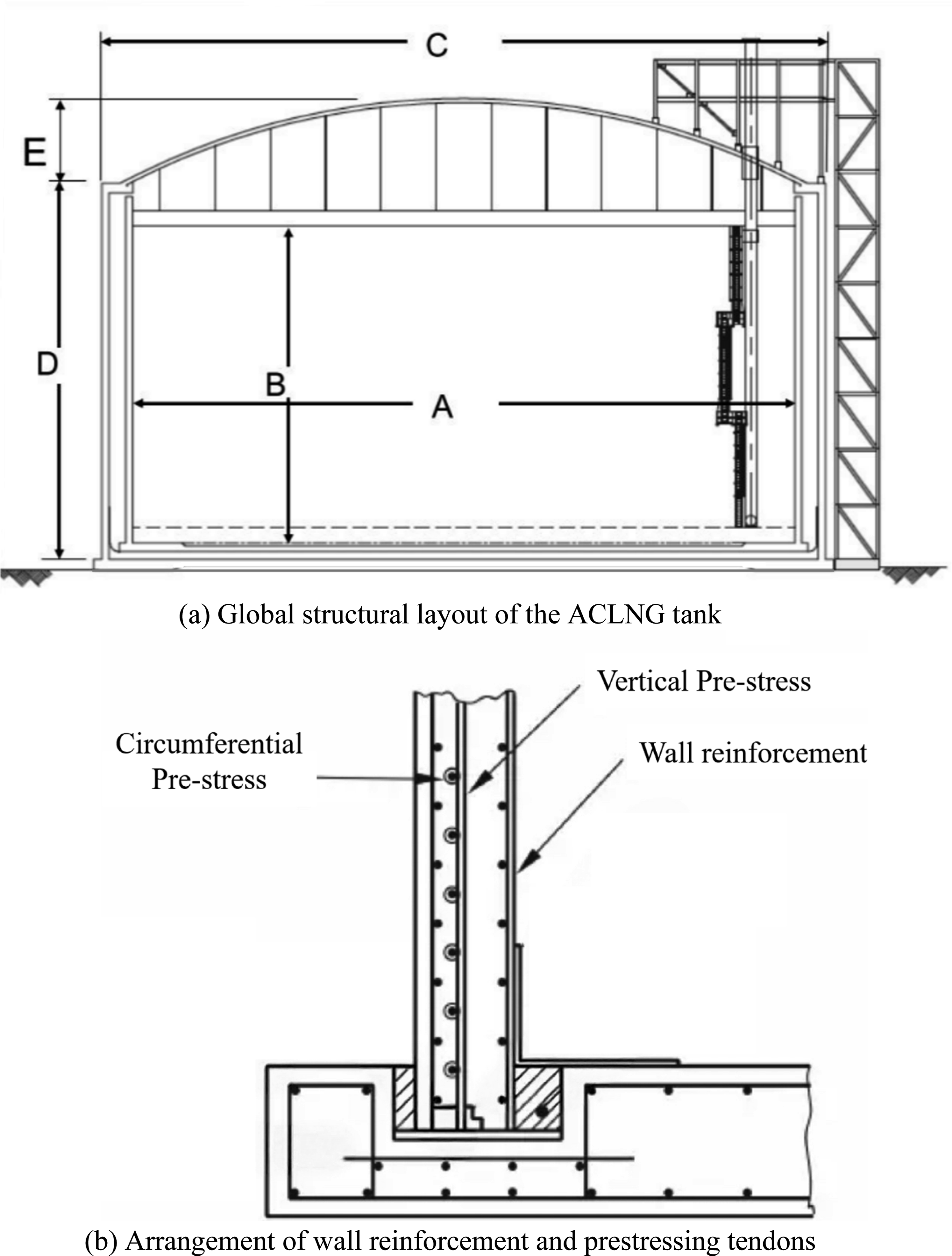
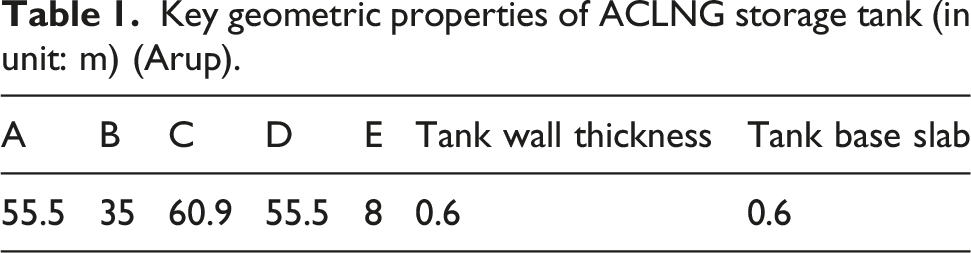
Based on the ACLNG tank configuration and the assumed thermal boundary conditions, the numerical analysis must capture the coupled effects of cryogenic temperature and blast induced high strain rates. Cryogenic exposure changes the mechanical performance of concrete as well as steel, while blast loading introduces strong rate dependence and damage evolution. Therefore, a temperature and rate-sensitive constitutive description is required. Besides NSC, UHPC is introduced as an alternative tank material to enhance structural robustness under the multi-hazard scenarios. This is motivated by the expected benefits of UHPC, including substantially higher mechanical performances, which are critical for maintaining containment integrity during blast events. Therefore, the modelling strategy considers both NSC and UHPC, enabling a direct comparison of damage localisation and overall blast resistance under cryogenic exposure. The following section provides a description of the constitutive relationships and material properties applied to concrete and reinforcement in LS-DYNA.
Material constitutive relationships and parameters
Karagozian & case concrete model
LS-DYNA provides several advanced constitutive models for simulating concrete behaviour under dynamic loading (e.g. KCC (Malvar et al., 1997), RHT (Borrvall and Riedel, 2011) as well as CSCM (Wu et al., 2012)). These models have been extensively applied in the analysis of NSC structures under the action of blast effects. Among them, the KCC model is particularly advantageous because its material parameters can be estimated directly from the uniaxial compressive strength, allowing reliable numerical implementation even when detailed experimental data are limited. In contrast, UHPC exhibits significantly different mechanical characteristics compared to NSC, including enhanced tensile strength, improved fracture resistance, and greater load-carrying capacity. As a result, the default parameter generation approach is not sufficient, and appropriate calibration of the KCC model parameters is required to accurately represent UHPC behaviour (Lin, 2018). Furthermore, exposure to cryogenic temperatures alters key material properties, such as stiffness, strength, and failure mechanisms, while strain-rate effects under blast loading further influence the structural response. Therefore, these temperature-dependent and rate-sensitive characteristics must be incorporated into the constitutive modelling to ensure accurate simulation of both NSC and UHPC under combined cryogenic and blast loading scenarios.
Strength surface parameters
In the KCC model, the material parameters can be generated directly based on the unconfined compressive strength of concrete. For NSC, the strength surface parameters are determined using the empirical relationships provided in equations (1)–(3), which describe the failure envelope of concrete under different stress conditions (Malvar et al., 2000). In these equations, 


Updated strength surface parameters for NSC.

Updated strength surface parameters for UHPC.

Within the KCC constitutive framework, the tensile strength of concrete under cryogenic conditions is an essential parameter, as it governs the cracking behaviour and residual tensile capacity of concrete structures at cryogenic temperatures. For NSC, Shi et al. (Shi et al., 2016) proposed an empirical relationship describing the variation in tensile strength (
The UHPC tensile strength values adopted in this study were 7.20 MPa at 25°C and 11.25 MPa at −160°C, based on the experimental results reported by Chi et al. (2024b).
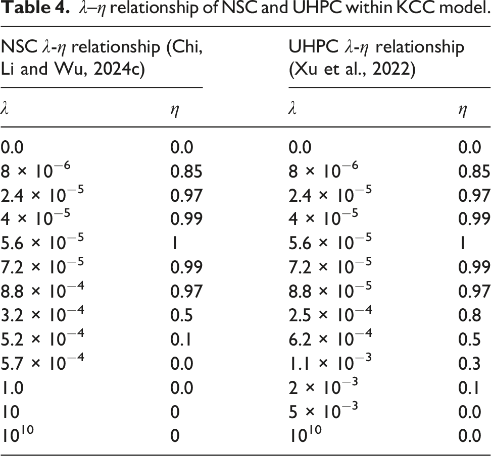
Relationship between λ and η
λ–η relationship of NSC and UHPC within KCC model.
Strain rate sensitivity
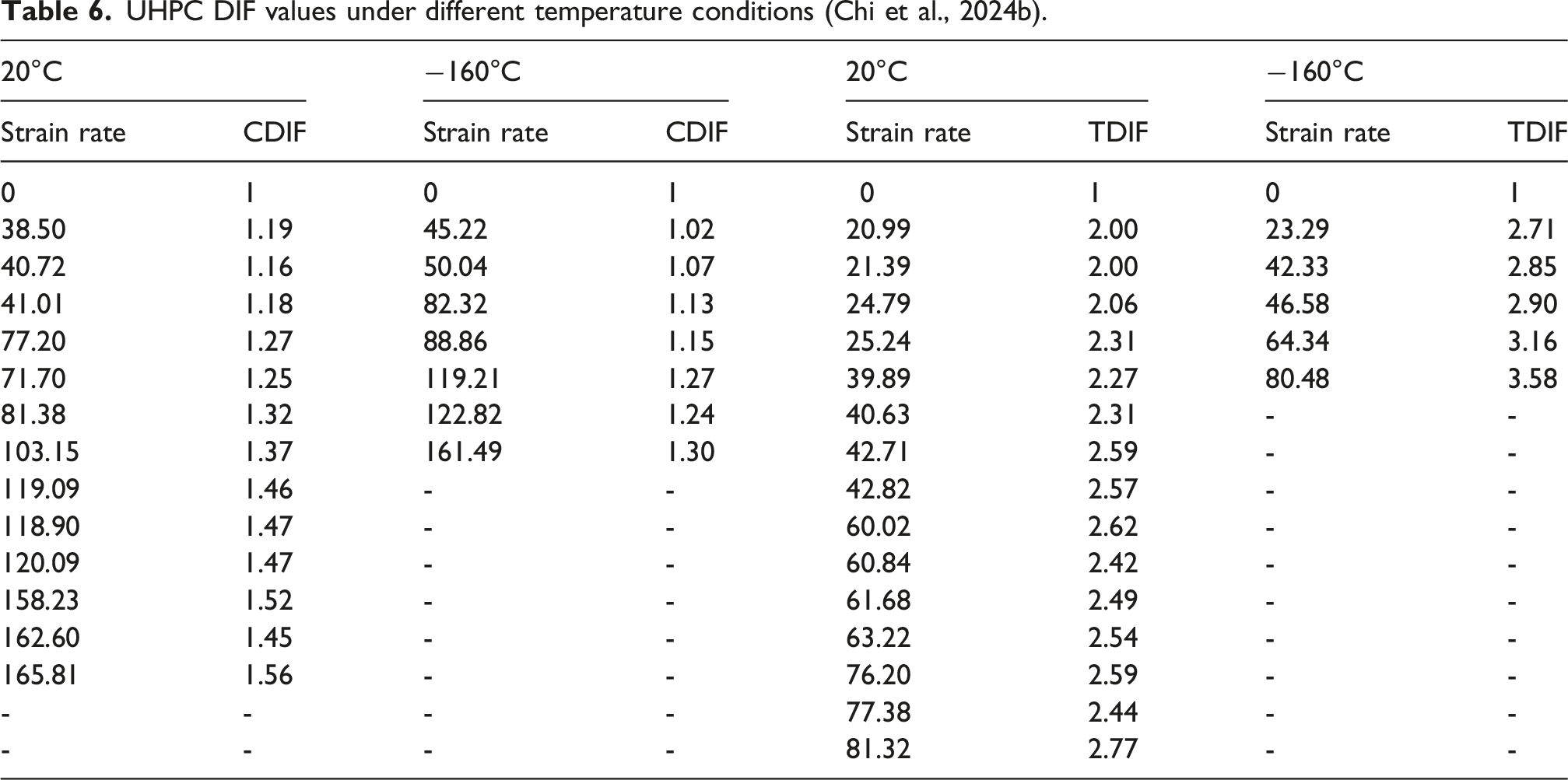
Material behaviour under dynamic loading is strongly influenced by strain rate effects. The dynamic increase factor (DIF) is widely used to characterise this rate dependency and is defined as the ratio of material strength under dynamic loading to its corresponding static strength.
NSC DIF values under different temperature conditions (Chi et al., 2024a).
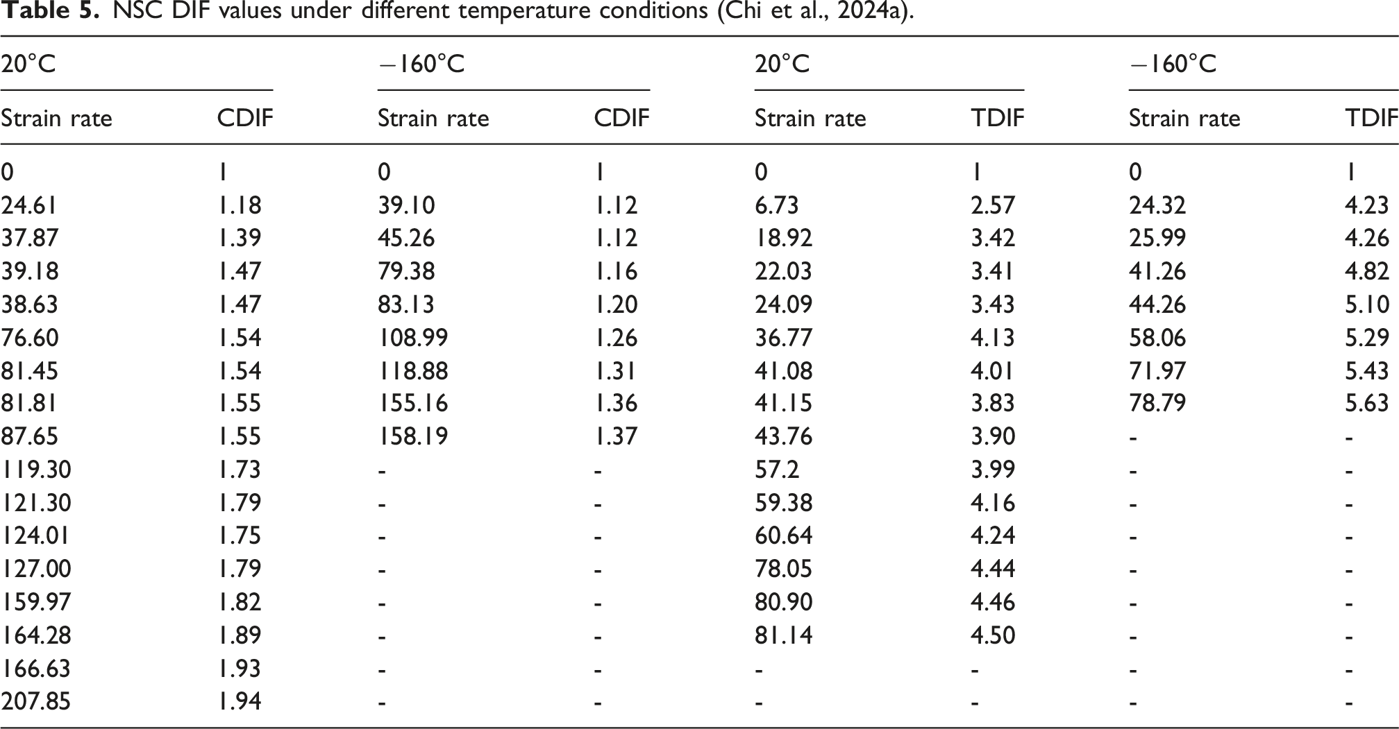
In contrast, the TDIF increases at −160°C. At this temperature, the frozen pore water forms a continuous ice skeleton within the concrete microstructure, which acts as a natural crack-bridging mechanism and enhances the resistance to crack initiation and propagation under dynamic tensile loading (Zhengwu et al., 2018). The ice-filled microcracks provide additional internal restraint and generate a prestressed effect that delays crack growth. These mechanisms collectively contribute to the enhanced tensile strain-rate sensitivity and the observed increase in TDIF at −160°C.
UHPC DIF values under different temperature conditions (Chi et al., 2024b).
Equation of state (EOS)
EOS for NSC at cryogenic temperature.


EOS for UHPC at cryogenic temperature.

Determination of damage accumulation parameters
Wu and Crawford (Wu and Crawford, 2015) reported that the parameter Single element test configuration (Xu et al., 2020). Single model stress-strain curve under uniaxial compression.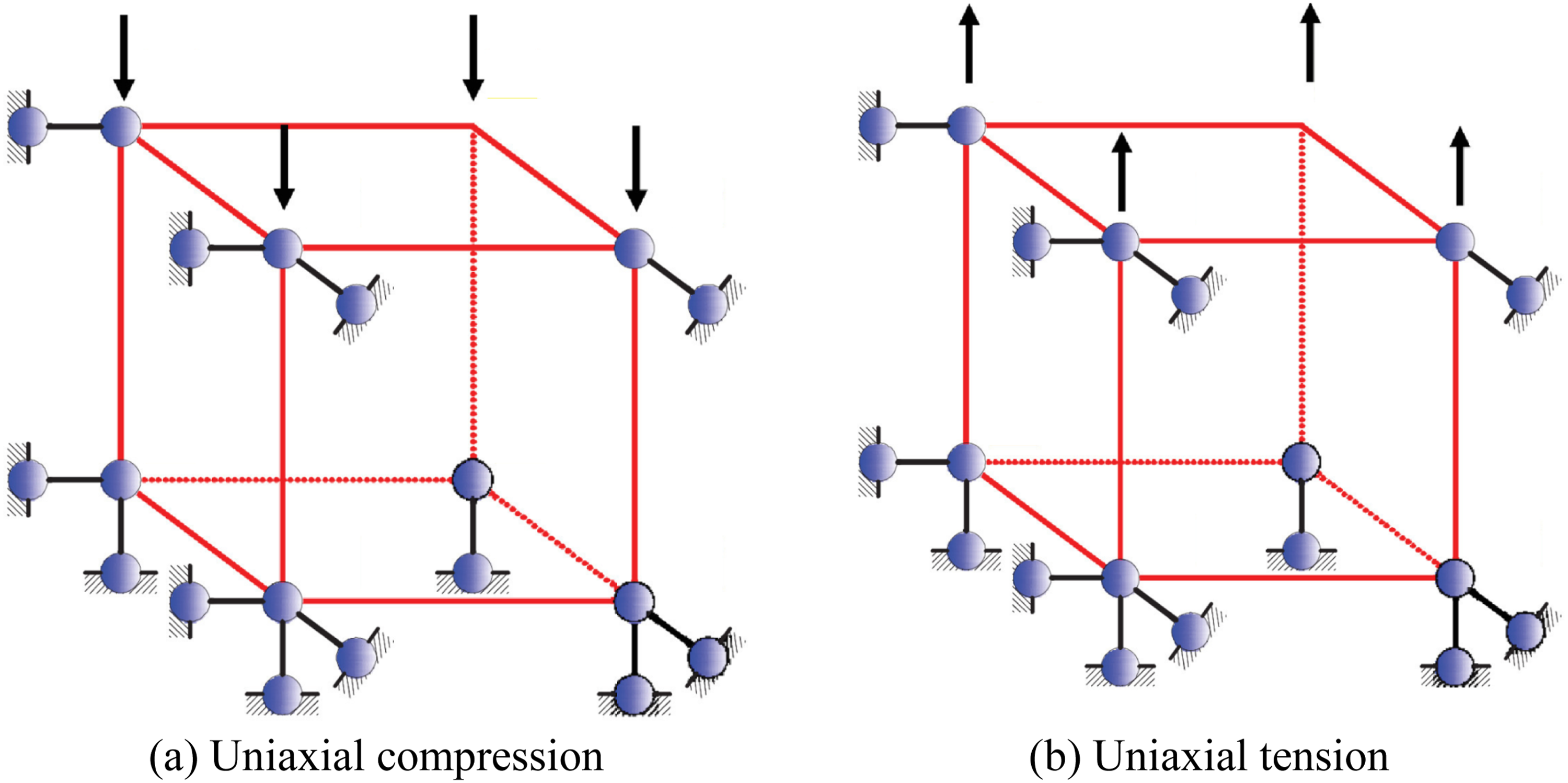
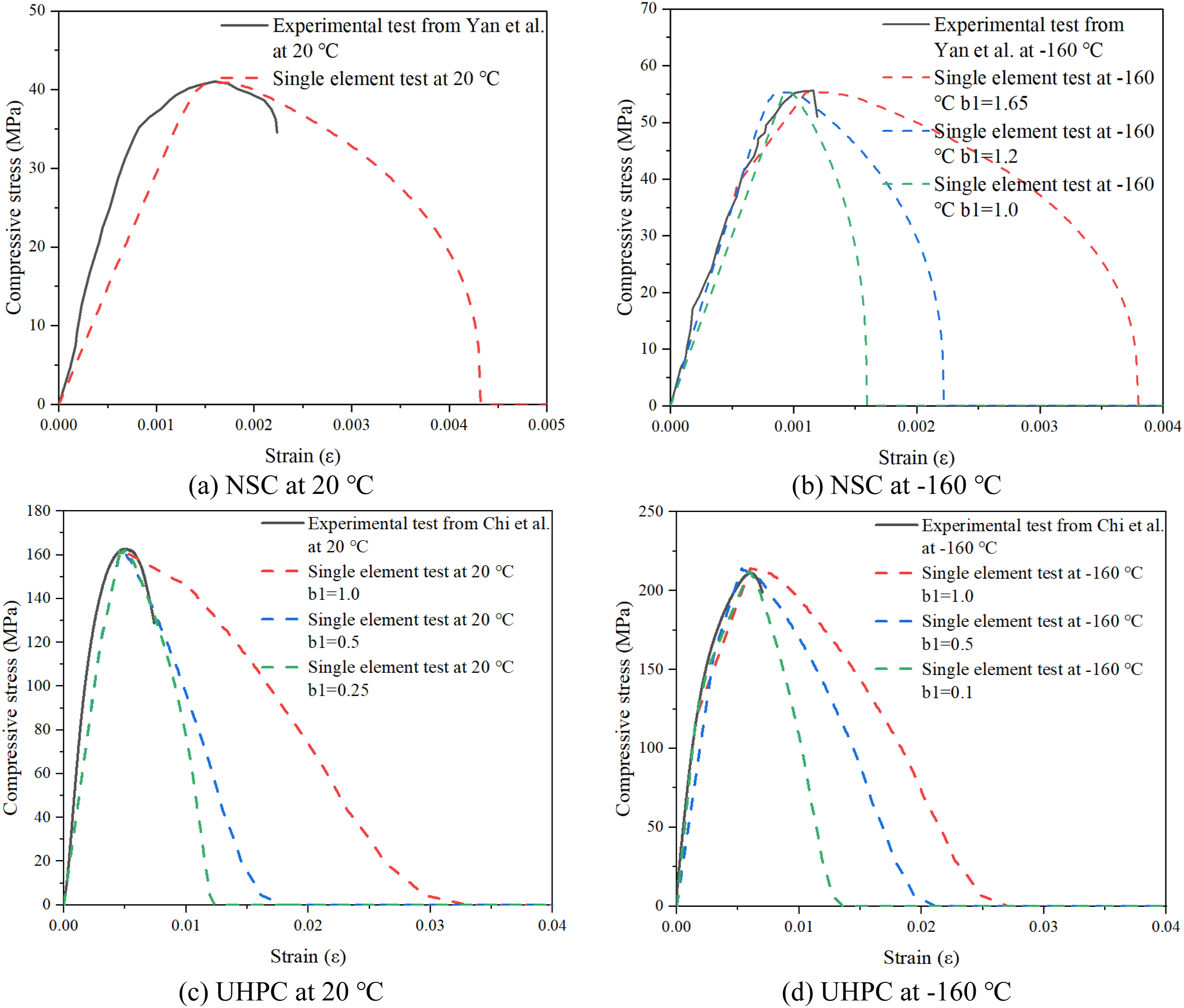
In the present investigation, the parameter Single model stress-strain curve under uniaxial tension.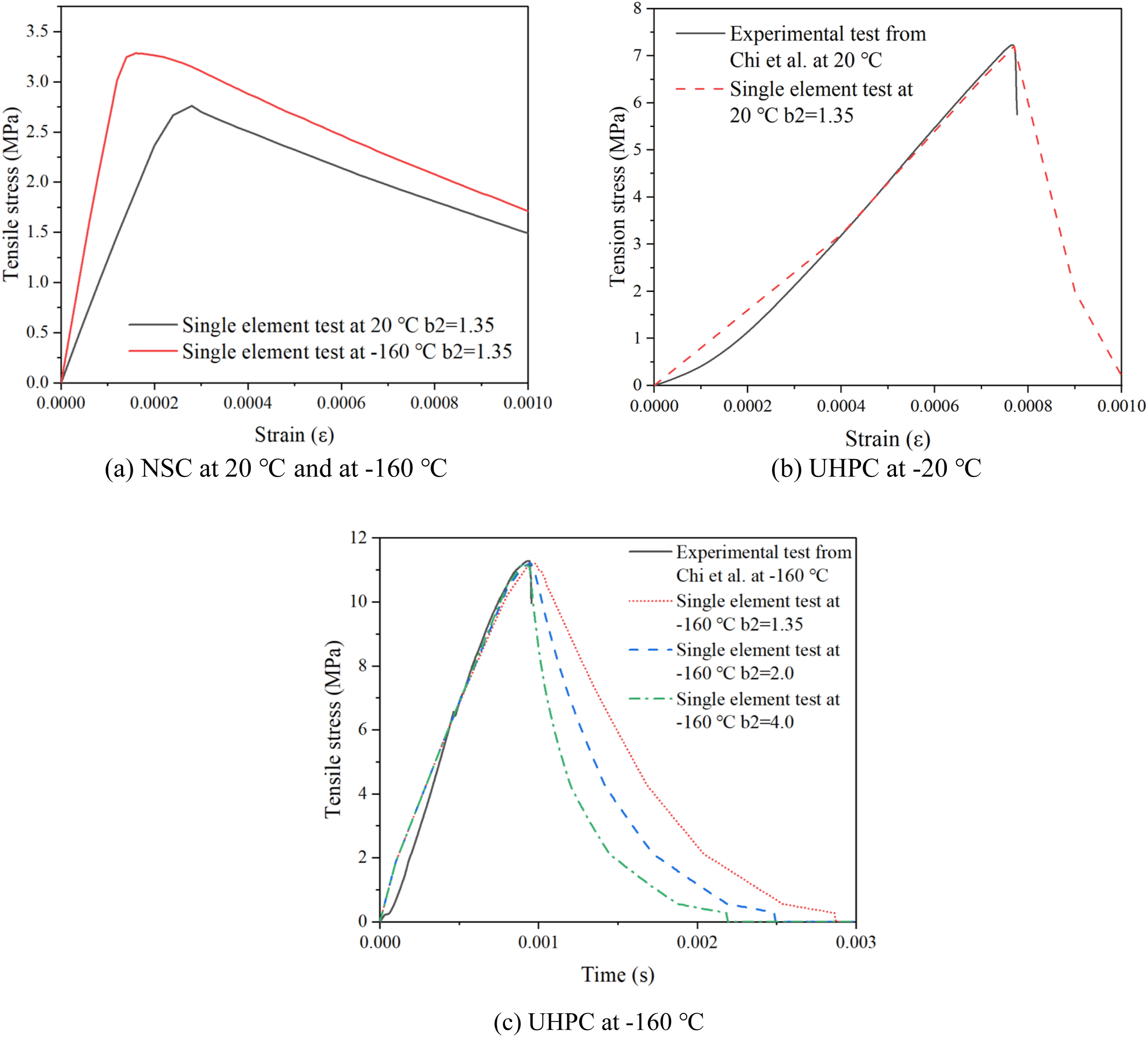
The KCC model includes a damage parameter,
Constitutive model for steel reinforcement
Effect of temperature on material
Steel reinforcement exhibits noticeable changes in mechanical behaviour when subjected to cryogenic temperatures. Chanda (2015) reported that X80 steel experienced moderate strength enhancement under cold conditions, with yield strength increasing by 4.8% at −30°C and 11.7% at −90°C relative to room temperature. Dahmani et al. (2007) further demonstrated that extremely low temperatures can significantly improve steel strength. Their study showed that reinforcing steel gained approximately 77.0% higher yield strength at −196°C, while prestressing steel showed a 17.9% increase at −165°C compared with ambient conditions. Additional investigations by Yan and Xie (2017b) on reinforced steel grades, including HRB335 and HRB400, revealed increases in stiffness and strength as temperature decreased. For HRB335 steel, reductions in temperature to −165°C resulted in increases of 9.5% in elastic modulus, 16.6% in yield strength, and 22.8% in ultimate strength. However, this strength improvement was accompanied by a decrease in ductility of approximately 30%. Similarly, Xie et al. (2023) examined mild steels such as Q235, Q355, and Q460 and found that cryogenic exposure led to considerable strength enhancement. In particular, Q235 steel showed increases of 61.1% in yield strength and 29.0% in ultimate strength at −165°C compared with room temperature. These findings demonstrate that while cryogenic temperatures improve the strength and stiffness of steel reinforcement, they may also reduce ductility, which is an important consideration for structural performance under extreme loading conditions.
Steel reinforcement exhibits distinct thermal behaviour compared to the surrounding concrete. Under cryogenic exposure, steel undergoes relatively small dimensional changes. This mismatch in thermal response between steel and concrete can help limit excessive deformation of the reinforcement, thereby contributing to the preservation of its structural function under low-temperature conditions. Some studies have indicated that the bond stiffness and bond strength are enhanced at low temperatures. Experimental pull-out tests by Vandewalle (1989) demonstrated that the ultimate bond strength between steel and concrete increased by 94.4% at −165°C, compared with ambient conditions. Similarly, Jin et al. (2023) and Zhang et al. (2023) evaluated the bond performance at cryogenic temperatures through combined pull-out tests and numerical simulations, reporting an approximately linear increase of 11.8% in ultimate bond strength as the temperature decreased from 20°C ∼ −120°C.
Yan and Xie (2017b) and Xie et al. (2023) investigated the mechanical behaviour of reinforcing steel under cryogenic temperature conditions. Their findings indicated that reductions in temperature resulted in increases in Young’s modulus, yield strength, as well as ultimate strength. However, a transition from ductile to brittle behaviour was observed for HRB335 and HRB400 reinforcing steels when the temperature decreased below approximately −80°C. The experimental trends of the normalised elastic modulus as well as tensile strength, respectively, in accordance with the results reported by Yan and Xie and Xie presented in Figure 5(a) and 5(b). Variation in elastic modulus and yield strength with temperature for different steels.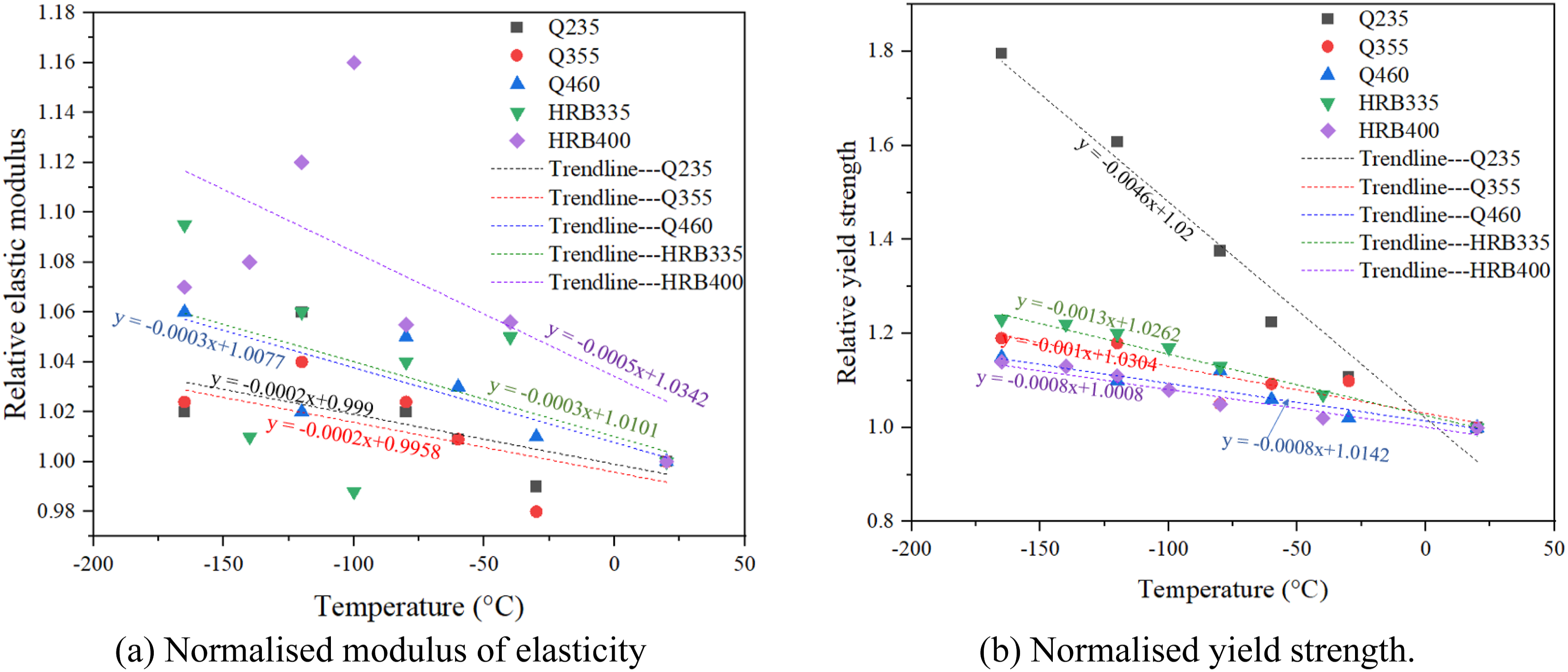
Based on the experimental observations, regression analysis was performed to establish temperature-dependent relationships for steel reinforcement properties. In this study, the variation in elastic modulus and yield strength with temperature was defined using empirical expressions derived from the HRB335 steel data, as given below:

Strain rate effect
The strain rate sensitivity of steel reinforcement is incorporated using the dynamic increase factors for yield and ultimate tensile strengths, as proposed in the CEB model (Béton, 1988), are expressed as follows:

Model validation for a reinforced concrete beam subjected to static loading under cryogenic conditions
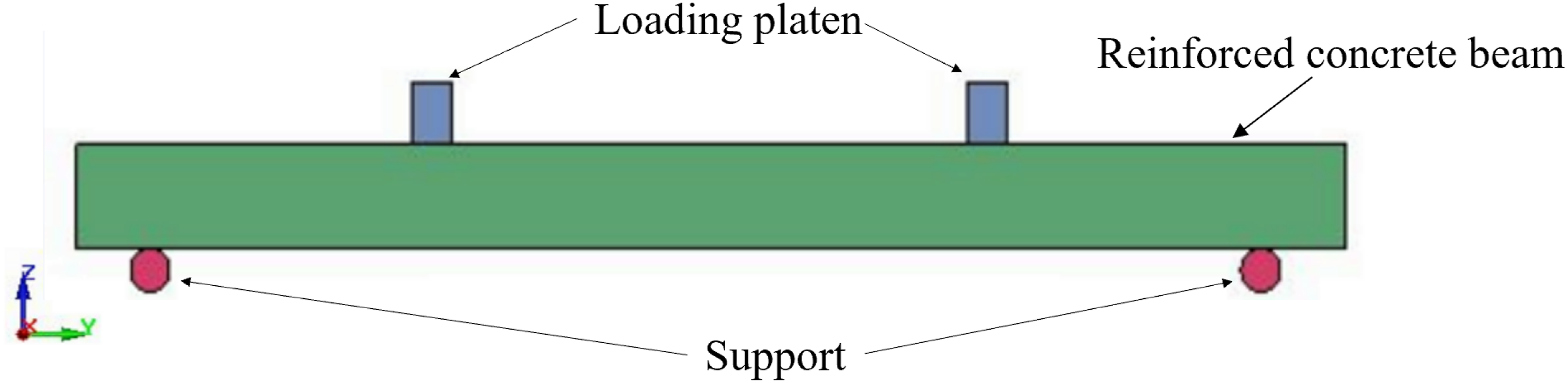
To validate the reliability of the reinforced concrete model under cryogenic conditions, the quasi-static bending test conducted by Liu et al. (2010) and Xiang-Lin et al. (2025) was used as a reference. According to the experimental data, the concrete compressive strength was approximately 20 MPa. The reinforced concrete beam specimens had dimensions of 40 mm × 40 mm × 300 mm. The longitudinal and secondary reinforcement bars had a diameter of 4 mm, while the stirrups were formed using steel wires with a diameter of 1.6 mm, as illustrated in Figure 6. Additional geometric and reinforcement details are available in Liu et al. (Liu et al., 2010; Xiang-Lin et al., 2025). A corresponding finite element model was developed in LS-DYNA to replicate the quasi-static test conditions, using the implicit solver to ensure numerical stability and accuracy. As shown in Figure 7, the numerical model consisted of three main components: the reinforced concrete beam, the loading platen, and the support system, which together simulated the experimental setup. A mesh sensitivity study was conducted to evaluate the influence of element size on numerical accuracy and computational efficiency. Three mesh schemes were examined. In Group 1, the element sizes assigned to the concrete, reinforcement, loading platen as well as support were 5 mm, 2.5 mm, 5 mm, as well as 5 mm, respectively. For Group 2, the mesh sizes were increased to 10 mm for the concrete, loading platen, and support, while a mesh size of 5 mm was used for the reinforcement. In Group 3, a coarser discretisation was adopted, with element sizes of 20 mm for the concrete, loading platen, and support, and 10 mm for the reinforcement. The results showed that further mesh refinement from group 2 to group 1 led to only minor changes in the predicted response while significantly increasing computational cost, whereas the coarser mesh in group 3 resulted in noticeable deviations in the numerical results. Therefore, the mesh configuration in group 2 was selected as a reasonable compromise between computational efficiency and numerical accuracy for subsequent analyses. Dimensions of reinforced concrete beam (Liu et al., 2010). Details of the reinforced concrete beam configuration.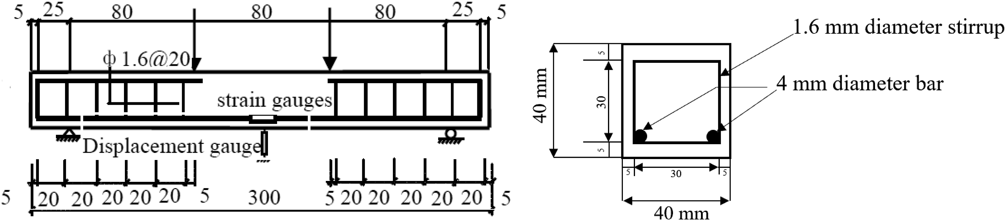
Material properties of concrete and steel reinforcement used in the quasi-static validation.
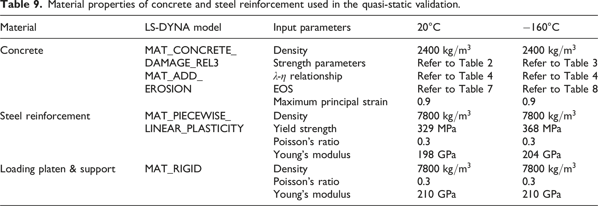
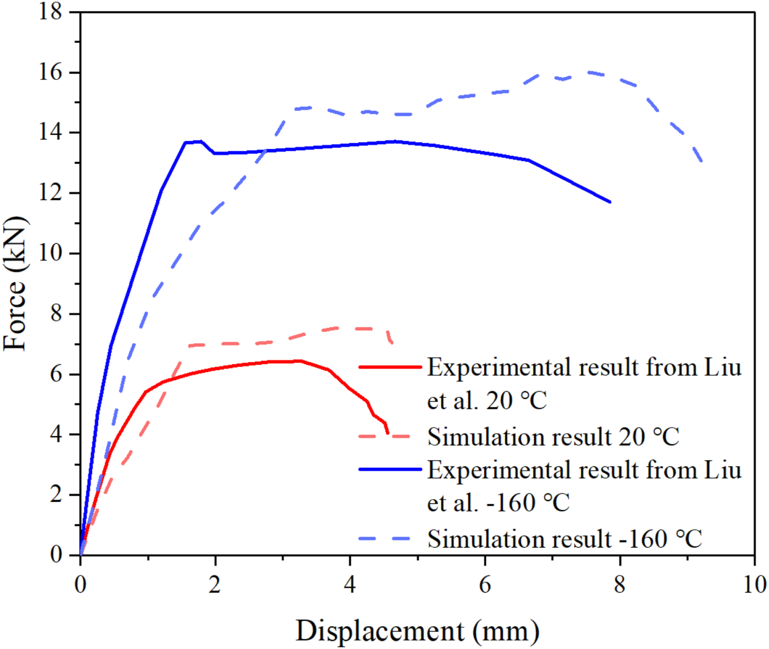
Figure 8 illustrates the damage pattern of the reinforced concrete beam subjected to displacement-controlled loading. The accuracy of the numerical model was assessed by comparing its predictions with the quasi-static four-point bending experimental results (Liu et al., 2010). As shown in Figure 9, the simulated load–deflection relationship at 20°C closely follows the experimental trend, with a discrepancy of nearly 11.43%. At −160°C, the numerical predictions show strong agreement with the corresponding test observations. The model effectively captured the influence of low temperature on both the material behaviour and the overall structural response. Notably, the beam exhibited greater stiffness and an increased load-bearing capacity at −160°C compared to ambient conditions, which is consistent with the expected strengthening effect of cryogenic exposure. The difference in the maximum deflection between the simulation and experiment at −160°C was approximately 12.51%, confirming the reliability and accuracy of the developed finite element model in reproducing the structural response under cryogenic conditions. Comparison of reinforced concrete beam failure patterns at (a) 20°C and (b) −160°C (Xiang-Lin et al., 2025). Load–deflection curves from experimental and simulation results.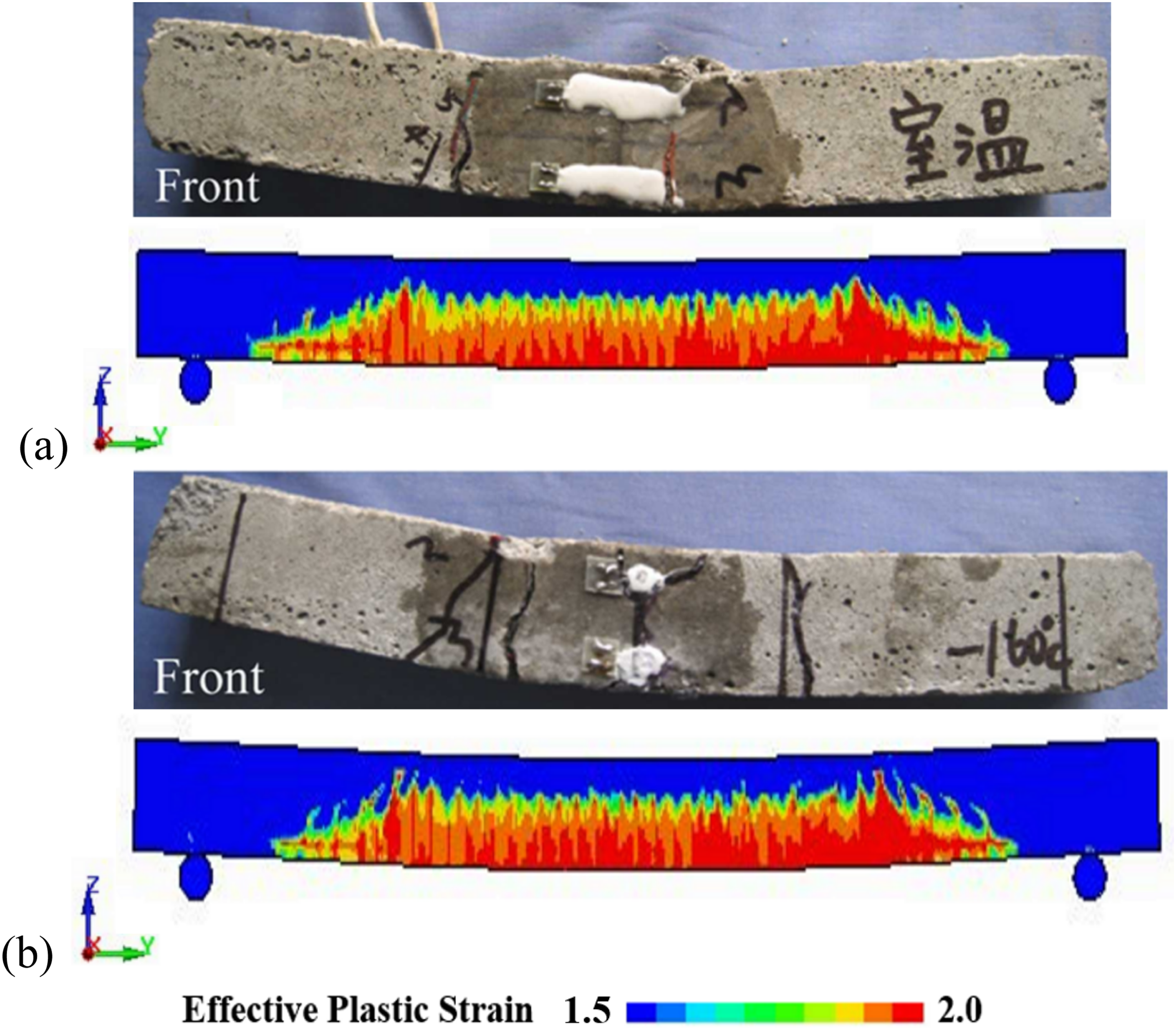
Model validation of reinforced concrete slab subjected to blast loading
Experimental programme
Validation of the numerical model was performed using blast experimental results obtained by Choi et al. (2018) on a prestressed reinforced concrete slab. The tested slab had dimensions of 1.0 m × 1.4 m × 0.3 m (width × length × thickness), and the reinforcement layout and rebars details are shown in Figure 10. The slab was reinforced with both prestressing tendons and reinforcing bars. Steel bars with a nominal diameter of 13 mm were arranged in two orthogonal directions to form a reinforcing mesh. The reinforcing bars were placed near both the top and bottom faces of the slab, with a concrete cover of 50 mm. The bar spacing in both primary and secondary direction was 100 mm. The slab was prestressed using 7-strand steel tendons with a nominal diameter of 15.2 mm and an ultimate tensile strength of 1860 MPa. Each tendon was applied with an initial prestressing force of approximately 510 kN. Geometric and reinforcement details of the prestressed concrete slab in the blast experiment (Choi et al., 2018) (unit: mm).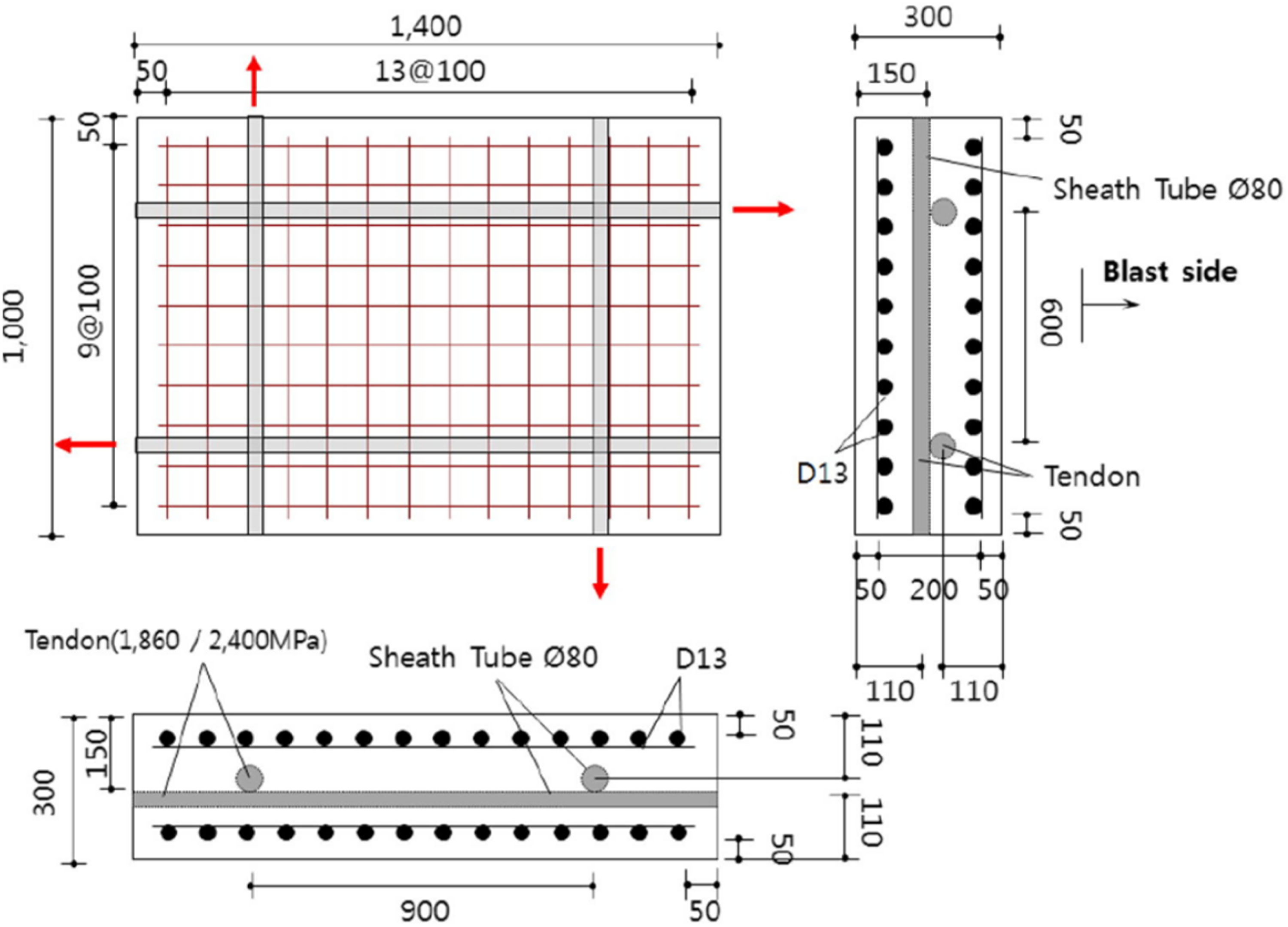
The blast loading was generated by a spherical explosive charge of 25 kg ANFO, detonated at a standoff distance of 1.0 m from the slab surface. The structural response of the slab was monitored during the test. In particular, the midspan deflection was measured using a linear variable differential transformer (LVDT) installed at the centre of the rear surface of the slab. After the blast event, the rear-surface crack patterns and damage distribution were recorded and used as key indicators for model validation.
Finite element model
A finite element model was established in LS-DYNA to replicate the experimental setup. The numerical model included the explosive, surrounding air domain, and the prestressed reinforced concrete slab, as illustrated in Figure 11. Numerical simulation model of the prestressed reinforced concrete slab.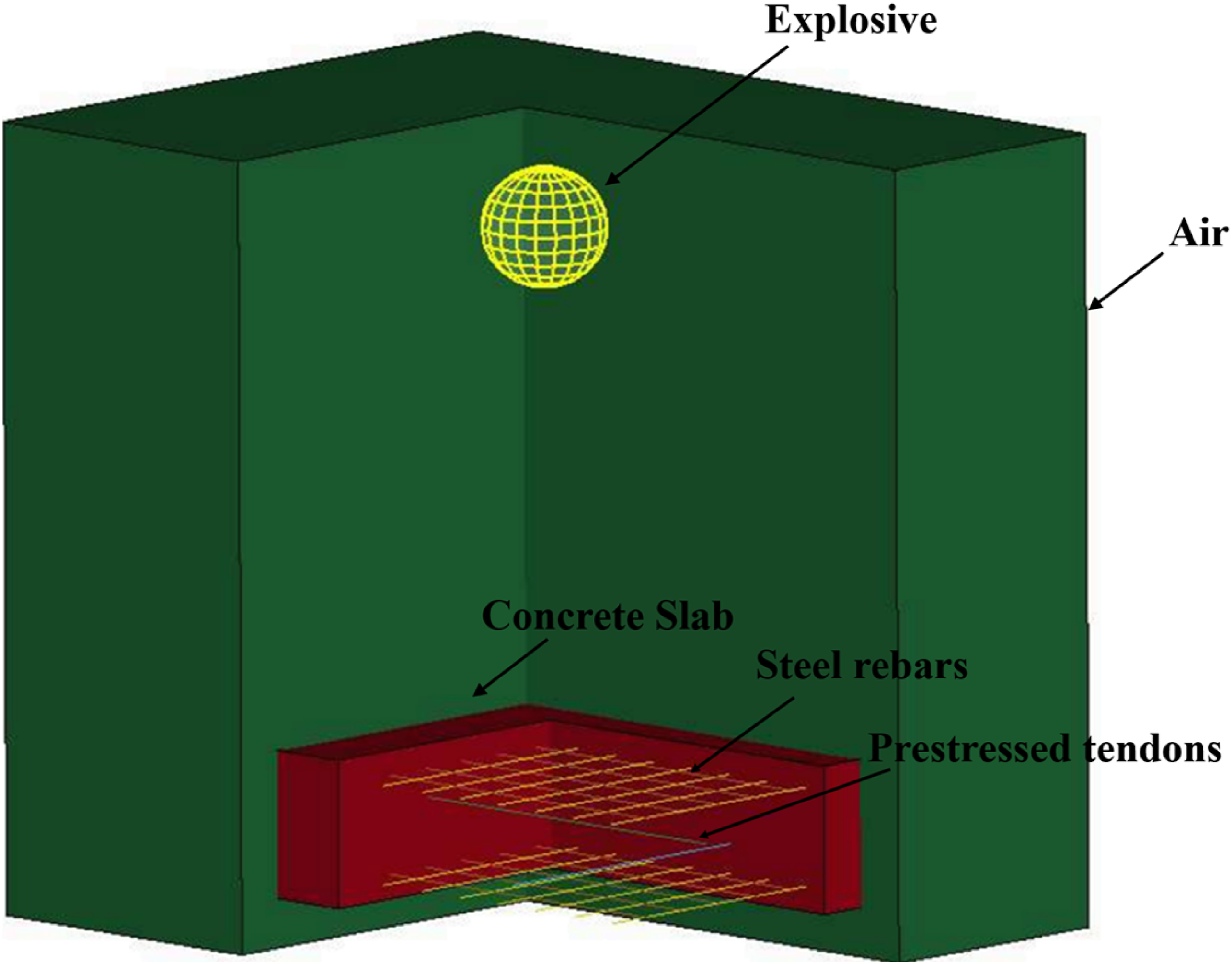
The air as well as explosive was represented utilising the Arbitrary Lagrangian–Eulerian (ALE) multi-material formulation, whereas the concrete slab was modelled using solid Lagrangian elements. Based on the mesh sensitivity analysis discussed in Section 4, a uniform element size of 10 mm was adopted throughout the model. Fluid-structure interaction (FSI) between the ALE domain and the concrete slab was implemented using the CONSTRAINED_LAGRANGE_IN_SOLID coupling algorithm to ensure accurate transmission of blast loads. The reinforcement was embedded within the concrete using the CONSTRAINED_BEAM_IN_SOLID approach.
The explosive charge was defined as a spherical ANFO charge with a mass of 25 kg, implemented utilising the INITIAL_VOLUME_FRACTION_GEOMETRY method. The concrete material behaviour was described utilising the KCC constitutive model, with parameters corresponding to C40 concrete at ambient temperature.
Material properties and constitutive models
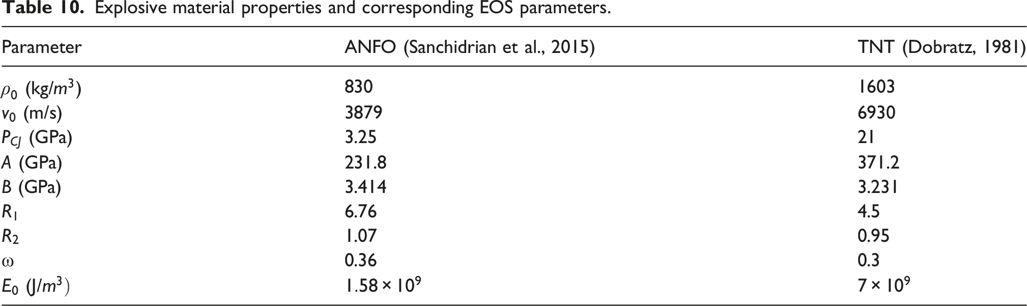
In LS-DYNA, air behaviour is commonly defined using the MAT_NULL material model in combination with the EOS_LINEAR_POLYNOMIAL (Hallquist, 2013). The general expression for pressure is given by:


Explosive material properties and corresponding EOS parameters.
The strain response of the prestressing tendon and concrete beam follows the condition of compatible condition (Do et al., 2018),
In the numerical model, prestressing was introduced by simulating thermal contraction of the tendons. Based on the compatibility of deformation between the concrete and prestressed tendon, the required temperature variation (

The temperature-dependent behaviour of the prestressing tendons was defined using MAT_ADD_THERMAL_EXPANSION, which enables the introduction of thermal strain through a prescribed temperature history. A LOAD_THERMAL_LOAD_CURVE was employed to specify the relationship between temperature and time for the tendons. In combination with this thermal loading, the CONTROL_DYNAMIC_RELAXATION option was adopted to establish the prestressing force by allowing the model to reach a stable equilibrium state prior to the blast analysis.
Model validation
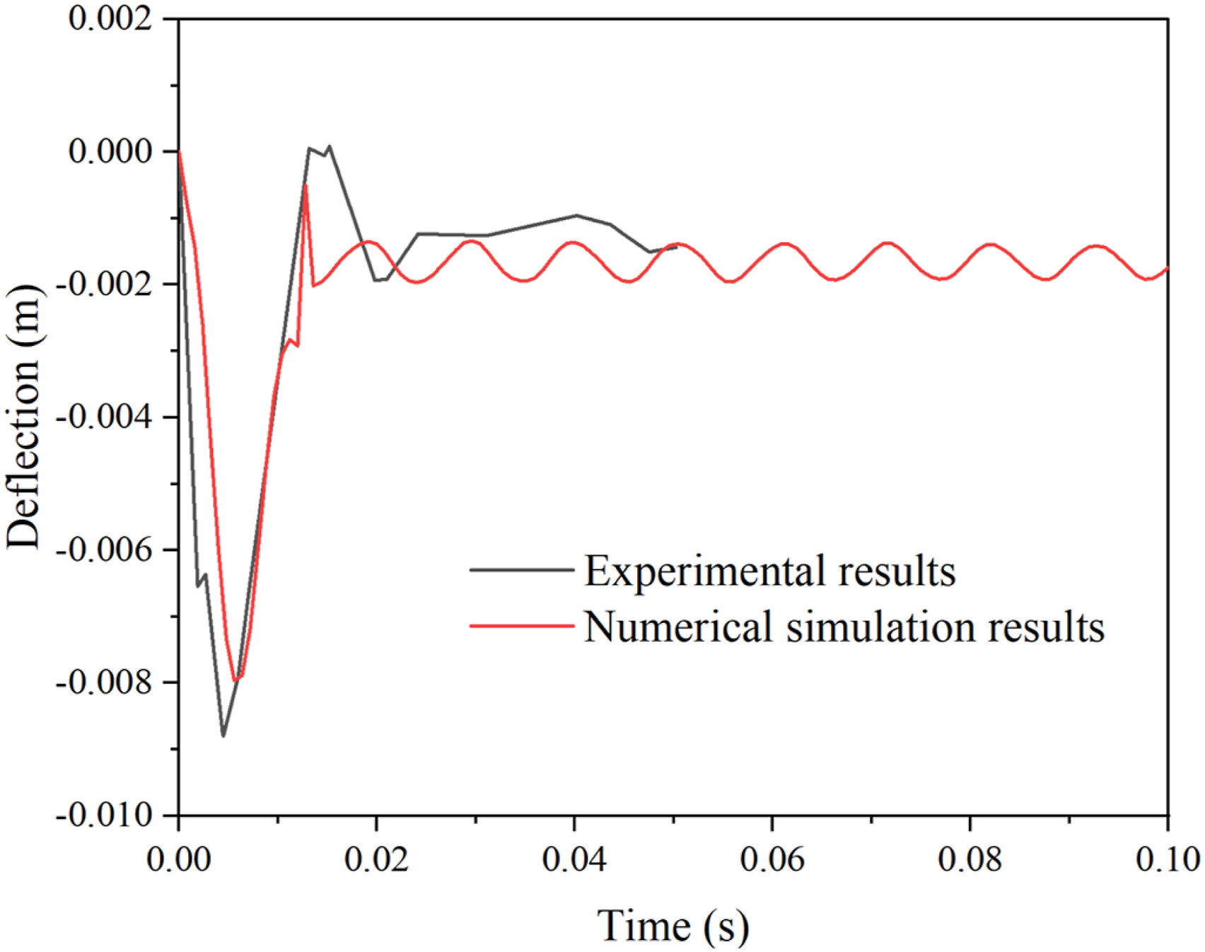
Figure 12 compares the experimentally observed rear-surface crack pattern with the numerically predicted failure pattern. It showed good agreement in damage distribution and crack orientation. Figure 13 presents the midspan displacement time-history curves obtained from both the experimental measurements and the numerical simulations. The deflection response was recorded using a LVDT positioned at the mid-point of the rear surface of the concrete slab. A close correlation between the experimental and numerical results is observed according to both the overall deformation trend and peak displacement response. The predicted response from the finite element model closely follows the experimentally measured behaviour. In addition, the maximum deflection values obtained from the simulation and the experiment differ by approximately 10.12%, demonstrating that the numerical model provides an accurate representation of the structural response of the prestressed concrete slab subjected to blast loading. Experimental and numerical failure pattern comparison of the RC slab. Midspan response time histories.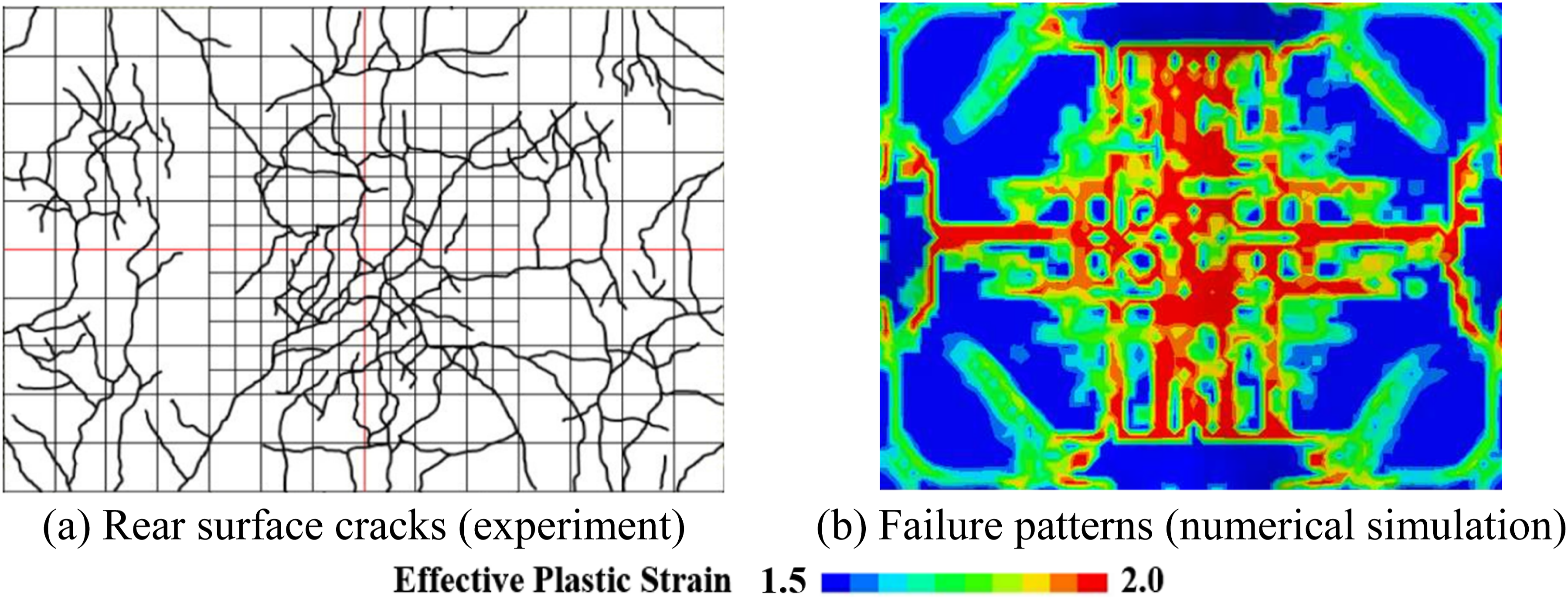
Structural performance of the ACLNG storage tank to blast loading at cryogenic temperature
To evaluate the dynamic behaviour of the ACLNG storage tank subjected to blast loading, a full-scale numerical model was developed. The computational domain included an air region covering a domain of 70 m × 70 m × 65 m along the X, Y, and Z directions, as illustrated in Figure 14. Finite element model of ACLNG storage tank.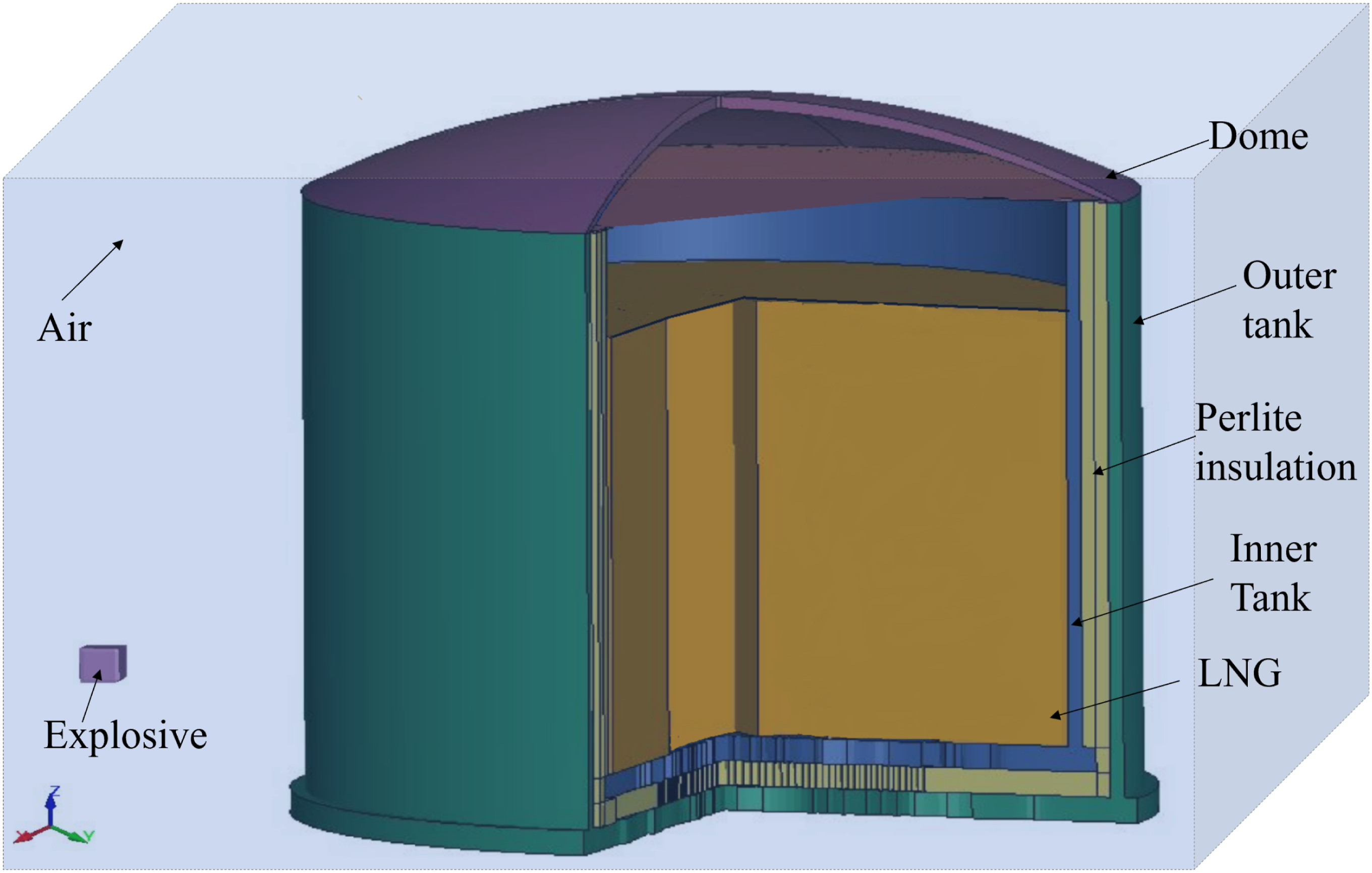
The LNG was modelled using MAT_NULL, consistent with the formulation adopted for air, while the pressure–volume relationship of LNG was defined using the Grüneisen equation of state. Under compressive conditions, the pressure is expressed as: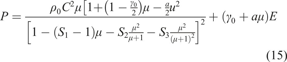
For expansion, the pressure is given by:
Key design and material values of the ACLNG storage tank.
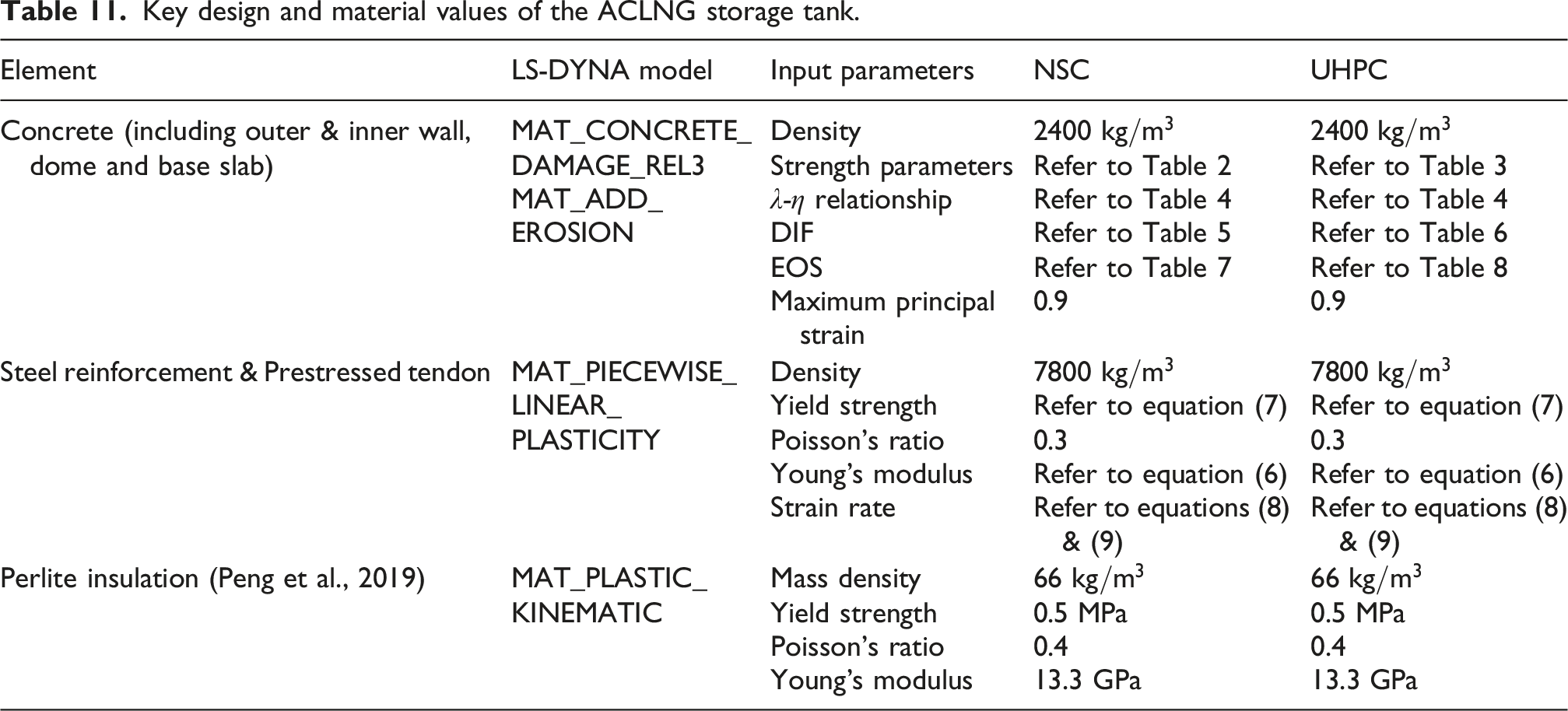
In accordance with AS 3961: 2017 (Standard, 2017), safety regulations require a minimum separation distance of 1.5 m between the tank and the surrounding protective barrier. Accordingly, a standoff distance of 1.5 m was adopted between the TNT and the outer tank wall in the present analysis.
The explosive charge was implemented using the INITIAL_VOLUME_FRACTION_GEOMETRY approach as a rectangular TNT-equivalent load of 1800 kg, simulating a small delivery vehicle scenario (Chipley et al., 2012).
Figure 15 shows the von Mises stress field in the ACLNG storage tank after prestressing was applied and before the blast load was introduced, representing the initial stress condition of the structure. The structural response under blast loading is presented in Figure 16. The outer and inner tanks exhibit different deformation characteristics, which are strongly influenced by the cryogenic temperature at −160°C. The exterior tank demonstrates a relatively uniform effective plastic strain distribution, demonstrating that the structural response is governed by overall bending behaviour (see Figure 16(a)). In contrast, the interior tank exhibits pronounced strain localisation, indicating a higher tendency for concentrated damage and potential local failure under blast loading (see Figure 16(b)). Stress distribution of the ACLNG storage tank after prestressing. Comparison of blast responses between the exterior and interior ACLNG storage tanks.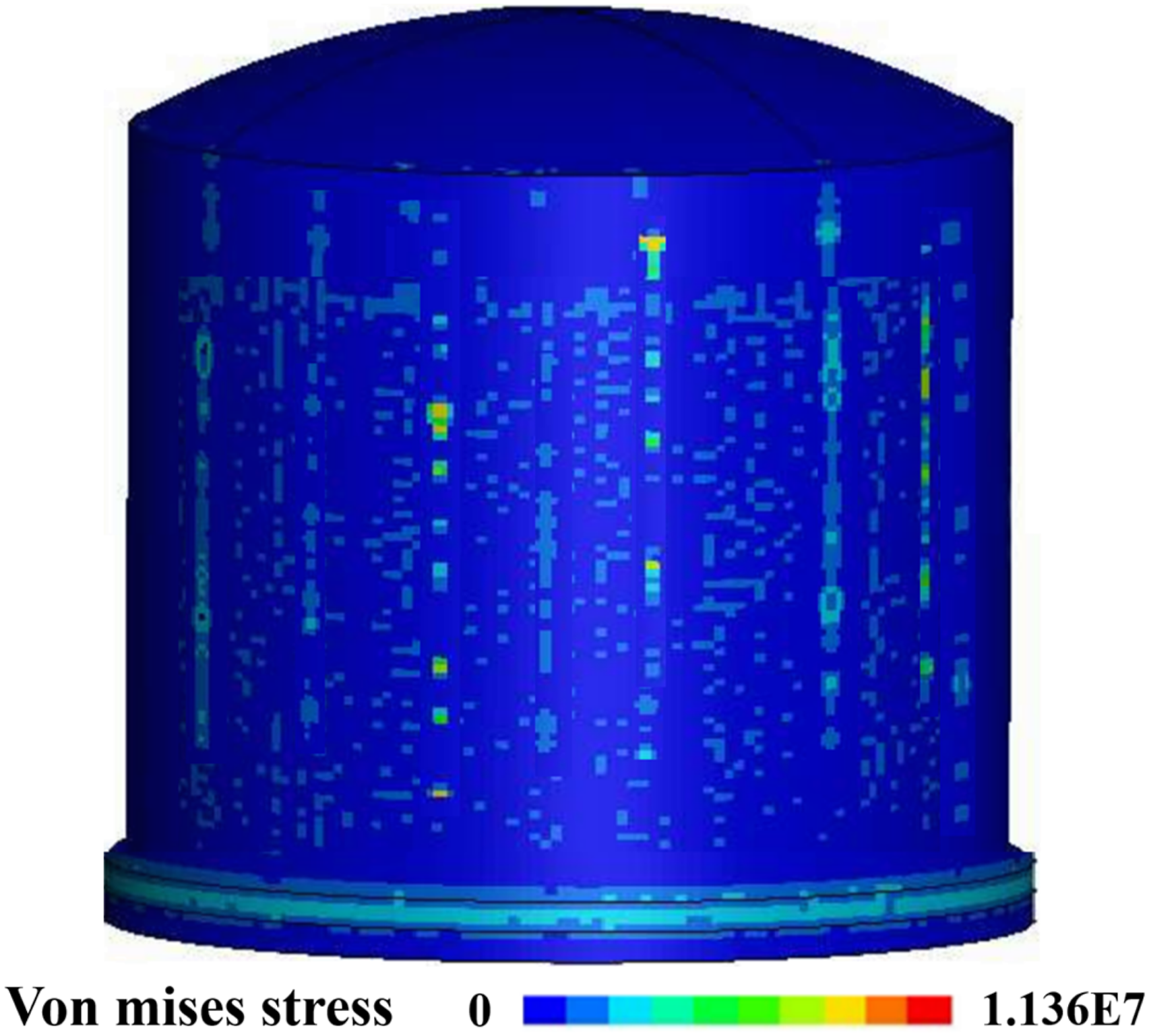
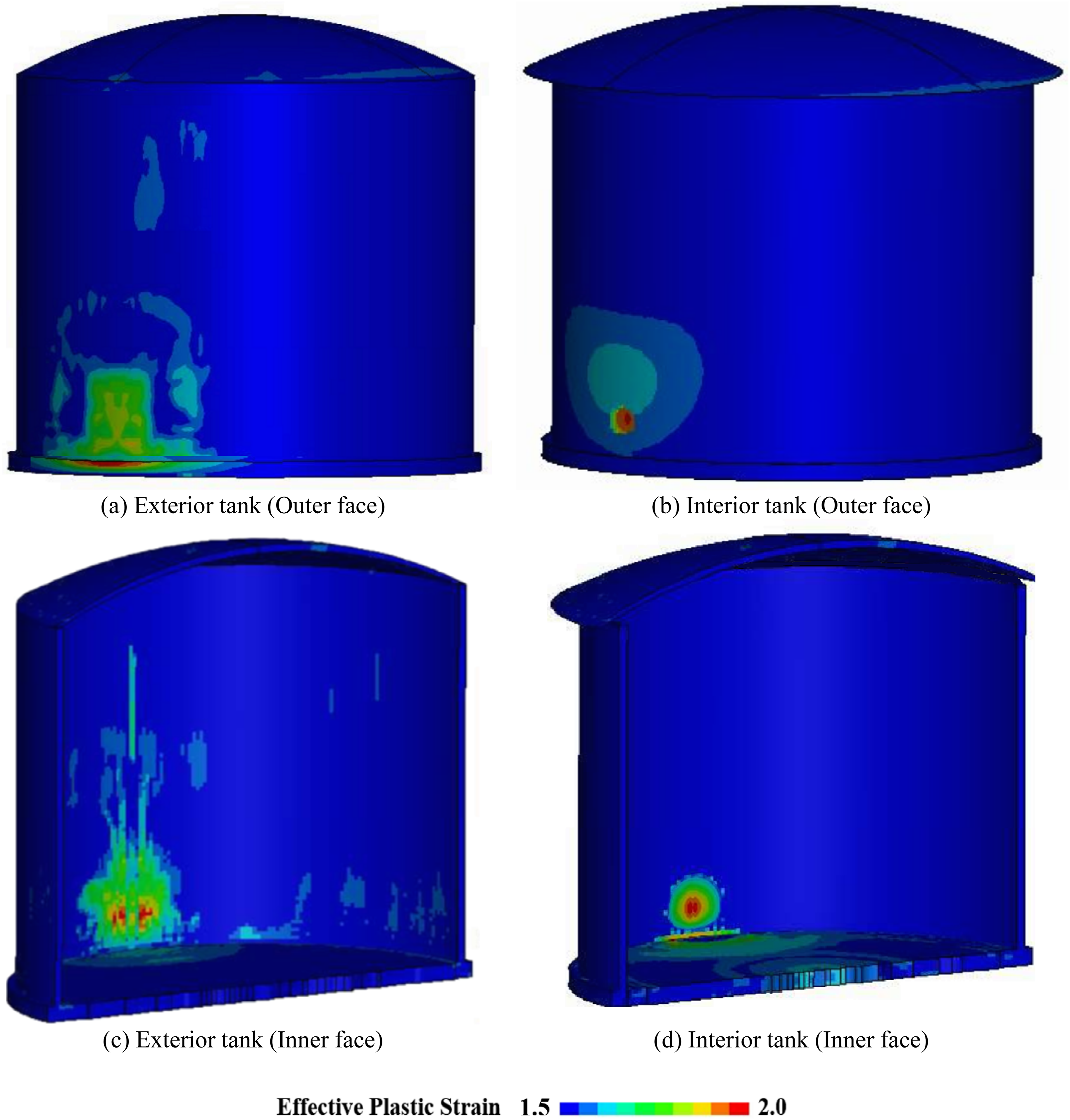
Cryogenic temperature exposure significantly affects the mechanical behaviour of concrete. Extremely low temperatures increase material brittleness and reduce deformation capacity, making the structure more prone to cracking and spalling when subjected to dynamic loading. The displacement time-history curves shown in Figure 17 further illustrate the transient response of the exterior tank, characterised by a rapid initial increase in displacement followed by a gradual reduction in deformation rate as the structural motion stabilises. The presence of cryogenic conditions may further amplify the peak deformation response, thereby increasing the structural demand on the tank. Time histories of displacement and total energy under blast loading.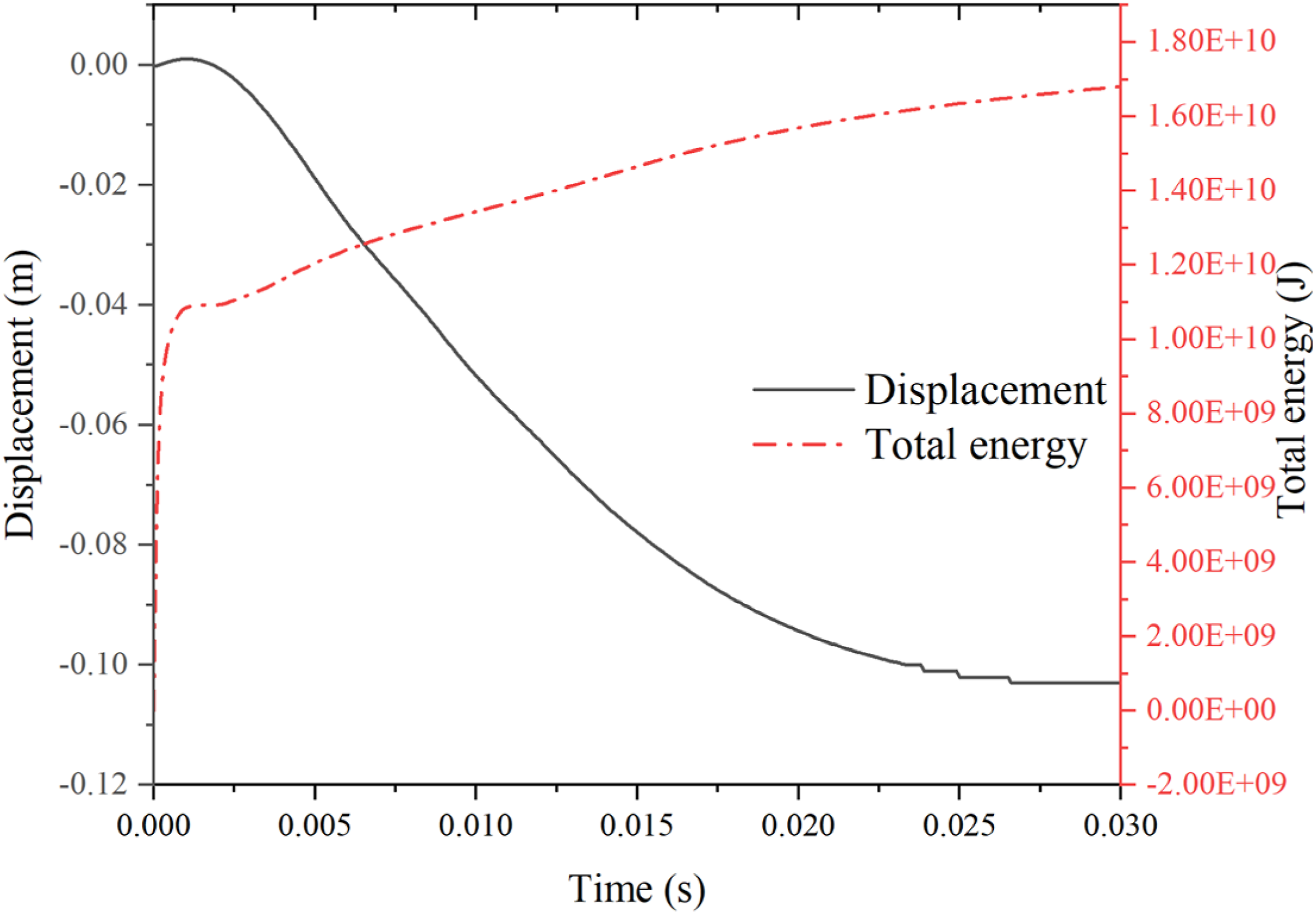
These results demonstrate the importance of evaluating the combined effects of prestressing, blast loading as well as cryogenic temperature on the structural response of ACLNG storage tanks. In particular, the interaction between the inner and outer tank components plays a critical role in determining the overall structural behaviour and damage resistance of the containment system under extreme loading conditions.
Parametric study
Impact of concrete material on structural response
The damage response of the inner tank was evaluated for two material configurations, namely NSC and UHPC, while the outer tank was constructed using NSC in both cases. The comparison, presented in Figures 16 and 18, corresponds to a blast scenario involving a 1.8 t TNT charge at a standoff distance of 1.5 m. For the NSC inner tank (Figure 16(b)), the damage zone is noticeably more extensive than that observed in the UHPC inner tank (Figure 18). Significant spalling and widespread material degradation are evident in the NSC case, indicating substantial structural damage and reduced load-carrying capacity. Damage response of the UHPC inner tank.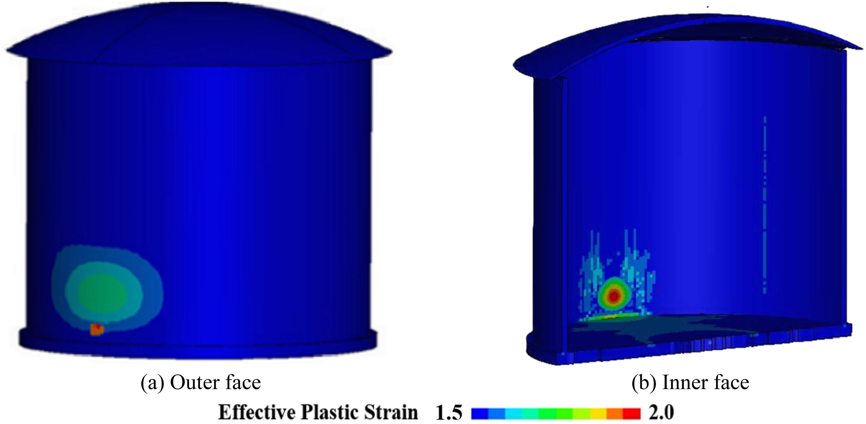
This behaviour is primarily associated with the relatively lower strength and reduced deformation resistance of NSC compared to UHPC. In addition, the exposure to cryogenic temperature conditions further influences the material response. Low temperatures tend to increase the brittleness of concrete, thereby reducing its ability to dissipate energy under dynamic loading. As a result, the NSC inner tank becomes more susceptible to blast-induced cracking, spalling, and structural deterioration, leading to a larger damaged region.
In contrast, the UHPC inner tank exhibits a more confined damage distribution and significantly less spalling. The superior mechanical properties of UHPC, including its higher compressive strength, improved tensile resistance, and enhanced energy absorption capacity, contribute to its improved resistance against blast-induced damage. Furthermore, UHPC demonstrates greater stability under cryogenic conditions, maintaining its structural integrity more effectively than NSC. Consequently, the UHPC inner tank shows a more controlled damage pattern and improved overall structural performance.
The comparative results clearly demonstrate the improved performance of UHPC relative to NSC for interior tank applications in ACLNG storage systems. The use of UHPC substantially reduces damage severity and limits the spatial extent of structural degradation, thereby enhancing the blast resistance and structural reliability of the containment system under combined cryogenic and blast loading conditions.
The selection of UHPC for both the exterior and interior tanks was motivated by the objective of evaluating high-performance material solutions capable of improving structural resistance under severe cryogenic and blast loading conditions. UHPC possesses superior mechanical properties, including higher strength, enhanced fracture resistance, and improved energy absorption capacity, which are expected to enhance the structural resilience of ACLNG containment systems.
As shown in Figure 19, the ACLNG storage tank constructed entirely with UHPC demonstrates significantly improved damage resistance compared to the NSC configuration presented in Figure 16. The UHPC outer tank exhibits a more confined damage region, with reduced spatial extent of effective plastic strain. Likewise, the UHPC inner tank shows a more localised damage response and improved structural integrity, indicating its enhanced ability to withstand blast-induced loading. The improved performance of UHPC can be attributed to its superior strength and resistance to crack initiation and propagation, which limit the development and expansion of blast-induced damage. Structural damage distribution in the ACLNG storage tank with UHPC.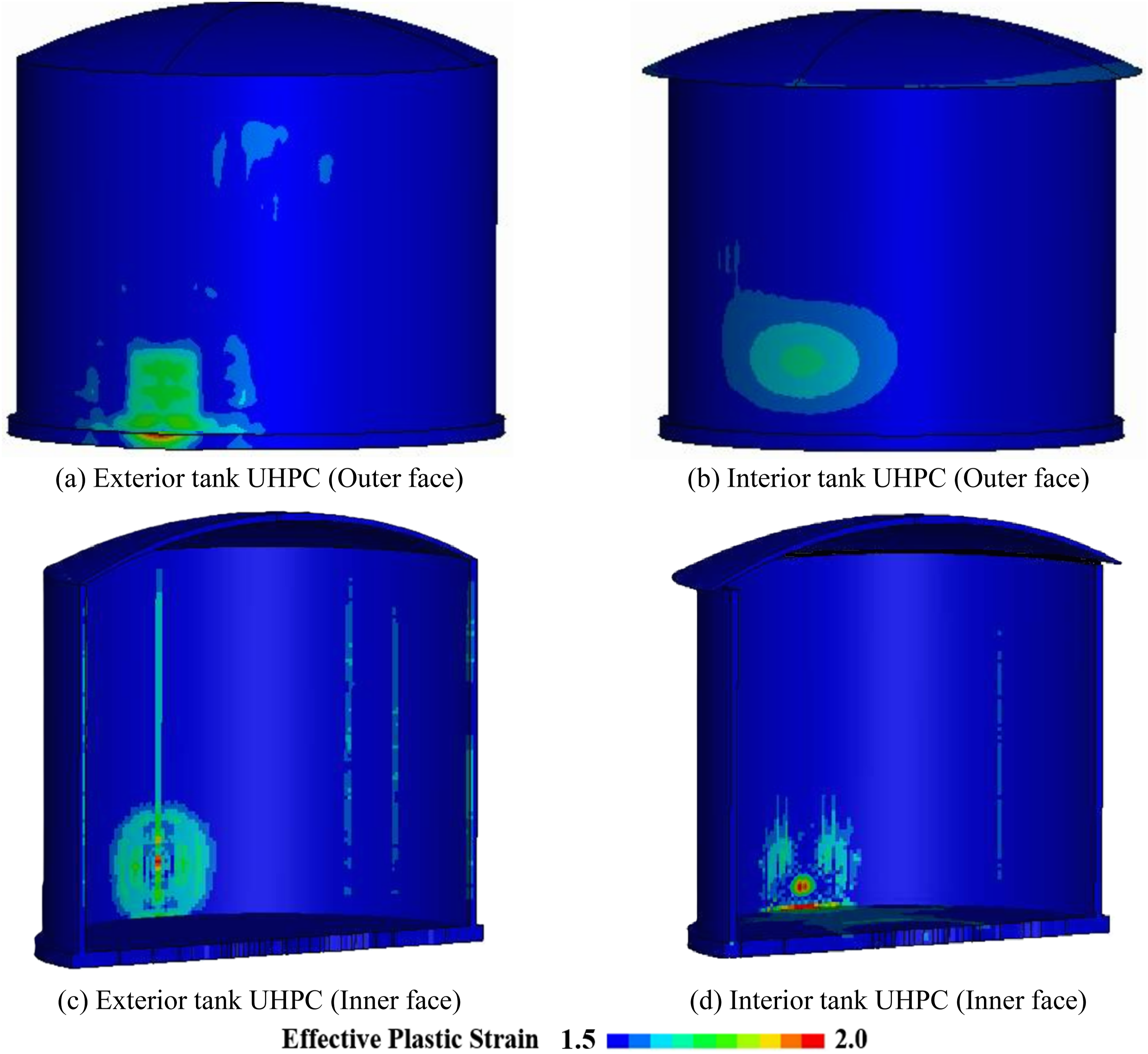
In contrast, the tanks constructed with NSC, as discussed in Section 6, show more extensive damage and greater susceptibility to cracking and spalling. This behaviour is associated with the comparatively lower strength and fracture resistance of NSC, particularly under the combined influence of cryogenic temperatures and high-intensity dynamic loading. These findings highlight the effectiveness of UHPC as a promising material for improving the blast resistance and structural safety of ACLNG storage tanks operating in extreme environments.
Impact of liquid level on structural response
The liquid filling level has a substantial influence on the blast behaviour of the inner tank in the ACLNG containment system. Figure 20 illustrates the damage distribution of the NSC inner tank subjected to a 1.8 t TNT blast under different liquid level conditions. At higher filling levels, such as the 75% case shown in Figure 20(a), the cryogenic LNG generates higher internal hydrostatic pressure on the tank wall, which provides additional confinement and limits structural deformation. When the filling level decreases to 50%, as presented in Figure 20(b), the reduction in internal pressure weakens this confinement effect, allowing larger deformation of the inner tank wall. Consequently, the damaged region observed in the 50% filling condition is noticeably larger than that in the fully filled and 75% filled scenarios. In the completely empty condition shown in Figure 20(c), the absence of internal LNG pressure results in the most severe damage extent among all cases. Effect of filling ratio on the damage distribution of the inner tank.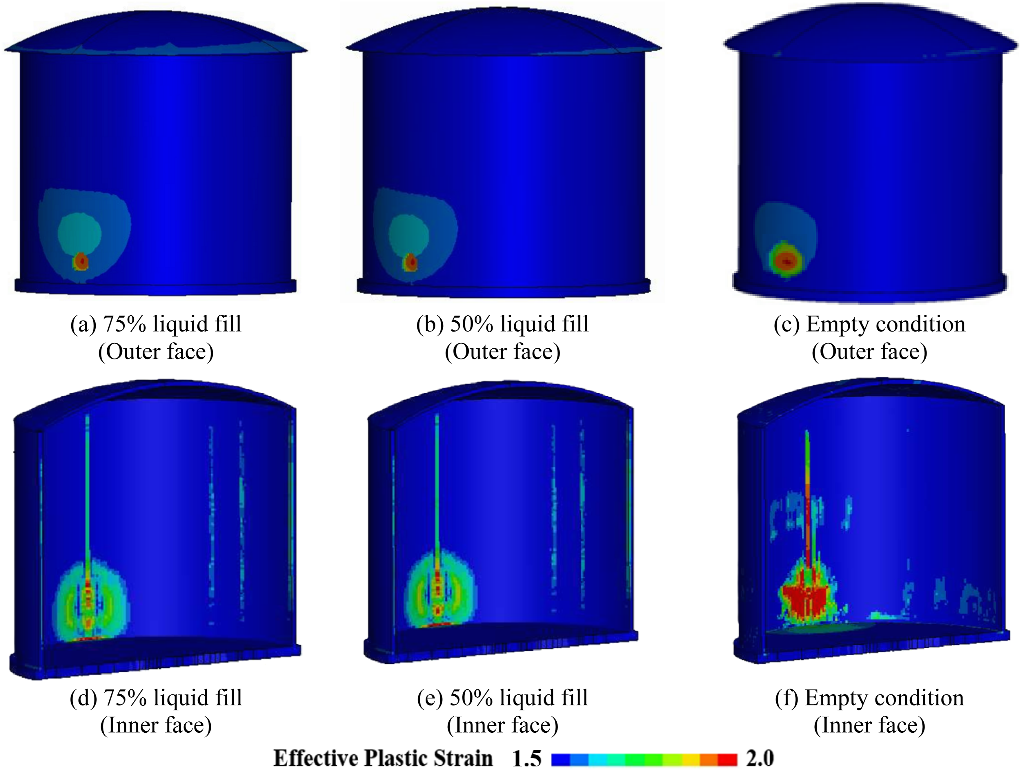
These findings demonstrate that the liquid level strongly affects the structural behaviour of the interior tank subjected to blast loading. Higher LNG filling levels improve the blast resistance and containment performance of the ACLNG storage system by providing internal restraint against deformation. The presence of cryogenic liquid enhances the structural stability of the tank and reduces the likelihood of large-scale structural failure when subjected to extreme dynamic loading.
Impact of charge weight on structural response
The damage characteristics of the ACLNG storage tank subjected to blast loading are strongly impacted by the TNT charge weight, as illustrated in Figures 21 and 22 for the outer and inner tanks, respectively. In this investigation, both the inner and outer tank structures were constructed using NSC. Four charge weights, namely 454 kg, 1800 kg, 4500 kg, and 27000 kg, were considered in this study. These charge magnitudes were selected based on equivalent TNT masses associated with potential vehicle-borne explosive threats, including SUV/van, water truck, and semitrailer scenarios (Chipley et al., 2012). Figure 21 illustrates the spatial distribution of damage in the outer tank under various TNT charge levels of 454 kg, 4500 kg as well as 27000 kg. As the explosive mass increases, both the intensity and extent of effective plastic strain in the outer tank increase noticeably. For the 454 kg charge (Figure 21(a)), deformation is primarily limited to localised areas, particularly near the base and upper sections of the tank wall. Conversely, when the charge weight is increased to 4500 kg (Figures 21(b) and 22(b)) and further to 27000 kg (Figures 21(c) and 22(c)), the affected regions become significantly larger, indicating more widespread structural damage across the tank. The elevated blast intensity induces severe material degradation, indicating that the concrete approaches its ultimate failure state, characterised by extensive cracking, spalling, and the formation of large openings in the tank wall. Outer tank damage patterns at different TNT charge levels. Inner tank damage patterns at different TNT charge levels.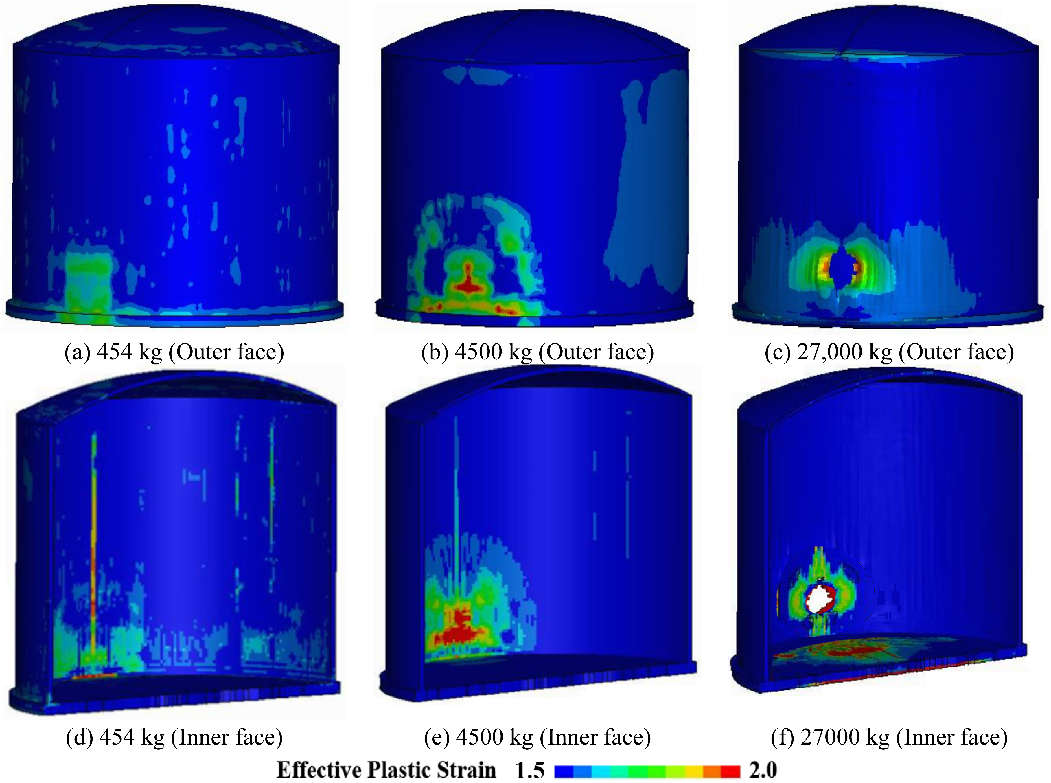
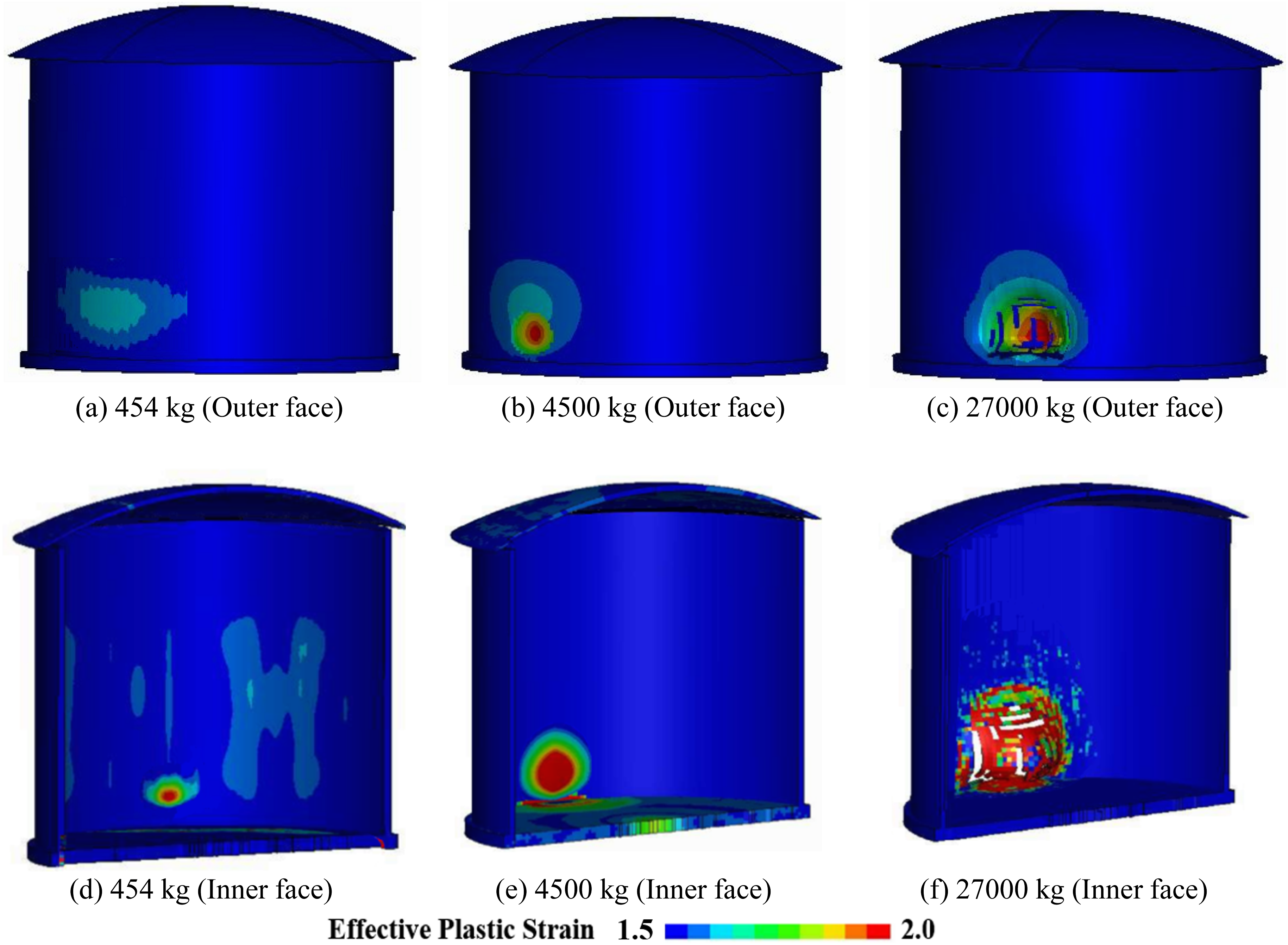
As the TNT charge weight increases, the resulting blast pressure and impulse acting on the ACLNG storage tank become more severe, leading to amplified deformation and more extensive damage across the interior and exterior tank systems.
Conclusion and limitations
Conclusions
This study presents a comprehensive evaluation of the structural behaviour of All Concrete Liquefied Natural Gas (ACLNG) storage tanks subjected to combined blast loading as well as cryogenic temperature conditions. • UHPC exhibited significantly improved performance compared with NSC when exposed to blast loading and cryogenic temperatures. UHPC showed enhanced resistance to damage and spalling, contributing to improved structural stability. The compressive strength of UHPC increased from 161.2 MPa at ambient temperature to 211.6 MPa at −160°C, representing a 31.5% enhancement. • The enhanced Karagozian & Case Concrete (KCC) modelling approach efficiently simulates how materials behave under varying temperatures, creating a reliable computational analysis framework. The validated models showed agreement with experimental data within approximately 11.43% and 12.51% discrepancy in load-deflection response at 20°C and −160°C respectively. • Exposure to cryogenic temperatures markedly alters the mechanical behaviour of concrete, resulting in increased brittleness and decreased ductility. • The LNG filling level had a pronounced influence on the blast resistance of the inner tank. At 75% fill, internal LNG hydrostatic pressure provided confinement that limited wall deformation and reduced damage extent compared to the 50% fill and empty conditions. The empty tank exhibited the most severe and spatially extensive damage among all filling scenarios, demonstrating the critical role of maintaining sufficient liquid content for structural safety under blast events. • As the TNT charge weight increased, damage to both tanks became more severe and widespread. At 454 kg, damage was limited to small localised areas, while at 4500 kg and 27000 kg, extensive cracking, spalling, and large openings developed across the tank walls.
Limitations
Despite the contributions of this study, several limitations should be noted. A uniform temperature distribution was assumed between −160°C (inner tank) and 20°C (outer tank), whereas actual conditions involve a thermal gradient through the insulation, which should be considered in future coupled thermal–structural analyses. Second, perfect bond between steel reinforcement and concrete was assumed throughout the analyses. Although experimental evidence supports enhanced bond strength at cryogenic temperatures, bond-slip behaviour under combined cryogenic and dynamic loading conditions warrants further investigation through dedicated pull-out test simulations. Finally, long-term effects such as prestress loss, freeze-thaw cycling, and material degradation under repeated cryogenic exposure were not considered and represent important directions for future experimental and numerical investigation.
Footnotes

Funding
The authors disclosed receipt of the following financial support for the research, authorship, and/or publication of this article: This study is supported by Australian Research Council (FT240100222).
Declaration of conflicting interests
The authors declared no potential conflicts of interest with respect to the research, authorship, and/or publication of this article.