





Abstract
The inerter-based response amplification device for dampers has been proposed to enhance seismic resilience, yet its real-world dynamic behavior lacks experimental validation. This study investigates a Cam-Type Response-Amplification Friction Damper (CRAFD) through shaking table test of full-scale steel frame subjected to nine seismic records (including near/far-field events). Key findings reveal that the CRAFD achieves: (1) Target amplification of friction forces (8 kN vs lateral FD’s 1.2 kN) and inertial mass, inducing significant negative stiffness in the primary structure; (2) The natural frequency decreased by a maximum of 34% (from 2.9 Hz to 1.91 Hz) under 0.4 g inputs, and the equivalent damping ratio was significantly improved compared to traditional FD; (3) Higher displacement mitigation and acceleration reduction by maintaining sliding status, which elevates energy dissipation ratio and prevents structural damage; (4) CRAFD suppresses out-of-plane deformation in V-shape linkages. These results validate CRAFD’s efficacy in seismic response control for engineering applications.
Keywords
Introduction
In passive control technology, dampers are one of the most widely used and typical passive control technologies (Koutsoloukas et al., 2022). Among a series of dampers available for engineering practices, the friction damper is widely used due to its simple configuration and long duration (Jaisee et al., 2021). The stable friction behavior can be achieved by using appropriate interface materials (Latour et al., 2014), and non-metallic materials are introduced to produce stable hysteresis curves of friction dampers (Paronesso and Lignos, 2021). Shaking table tests and numerical analyses have demonstrated that friction dampers with rotational or diagonal configurations can effectively mitigate the seismic response of frame structures (Couch et al., 2023; Jarrahi et al., 2020). In addition, new configuration of friction damper is used in the seismic retrofitting of existing concrete frames and shows effective in protecting the building (Zou et al., 2020). Meanwhile, corrosion or grease contamination during the service lives of friction dampers may lead to variations in the friction coefficient, potentially reducing their energy dissipation capacity (Chan and Tang, 2022).
Although the conventional friction damper shows its ability on seismic protection, new types of configuration are developed to improve the performance. Since the friction force depends on the preload, two-level friction dampers have been developed to address insufficient energy dissipation under either small or large earthquakes (Ghorbani and Rofooei, 2020; Huang et al., 2025; Yang et al., 2024; Yang et al., 2025). In addition, a rotational two-level friction damper is proposed (Huang et al., 2024), which is applicable on the joints in frame buildings. Particularly, the two-level force helps to reduce the acceleration response of buildings, which is beneficial for high-tech factories and hospitals (Chien and Guo, 2024). As buildings equipped with dampers may be subjected to earthquakes of varying intensities, the multi-stage behavior becomes important for the friction damper. Alternatively, the multi-stage behavior can be also achieved by adding other dampers on the friction damper. For example, the metallic damper in series with the friction damper generates two-stage hysteresis curves under seismic inputs (Xu et al., 2024; Zhai et al., 2024; Zhang et al., 2024). Another metallic-friction hybrid damper employs metal tube in series with two friction dampers, the multi-level behavior can be also achieved using SMA damper (Shi et al., 2024), self-centering devices (Ke et al., 2025) and electromagnetic devices (Shi et al., 2022).
In large-scale buildings, the friction damper needs huge preload to generate enough sliding forces, while the larger preload leads to more relaxation in preloads over time (Demonceau et al., 2020). Moreover, interlayer deformation in such structures is typically limited, which reduces the energy dissipation capacity of the dampers. Therefore, a rotational amplification device is proposed to improve the performance of the friction damper (Naeem and Kim, 2020). Other amplification devices are developed to improve the stiffness and damping effect of viscoelastic dampers and for high rise buildings (Bao et al., 2024; Jarrahi et al., 2020; Xu et al., 2024, 2024c). Scissor-Jack device, consisting of several braces, is also an effective device to amplify the damping force (Yang et al., 2025). For the rotational friction damper, a curved amplification device with guiding system and a level-ration device are developed to provide amplified axial friction forces (Gao et al., 2024; Wang et al., 2025).
The ball-screw pair, widely used in inerters, provides another approach to amplification of damping force (Duan et al., 2024; Liu et al., 2025; Wang et al., 2019). By converting axial motion into rotational motion, it can amplify the apparent mass by several hundred times (Liu et al., 2022). Apart from the inerter, the ball-screw pair can also be used in amplification of damping forces. The inerter-based amplified friction damper, which employs the ball-screw pair, is proposed to provide huge friction force at small preloads (Kong et al., 2025; Liu et al., 2024; Zhao et al., 2022). In addition, a cam-type amplifier, applicable on friction and shape memory alloy, is developed to generate huge damping force (Kong et al., 2024; Zhao et al., 2024). Besides, the ball-screw pair is also applicable on electromagnetic (Shen et al., 2022) and sand dampers (Ma et al., 2025). Although a series of inerter-based dampers are proposed, there is only limited papers reporting the shaking table test of structures with a real-world device. Existing tests show that the inerter in base isolation helps to reduce the displacement and base shear response (Li et al., 2025; Nanyu et al., 2025; Pietrosanti et al., 2021). Another shaking table test of a multi-story building equipped with an inerter shows that viscous inerter performs better than the hysteresis one (Deastra et al., 2023).
To date, although a series of inerter and inerter-based dampers are developed, there are limited literatures reporting the dynamic behaviors of the real-world devices, especially the seismic performance on a shaking table. The authors propose Cam-Type Response-Amplification Friction Damper (CRAFD) and investigates the effect on seismic mitigation numerically (Zhao et al., 2024). Meanwhile, the significant nonlinearity makes it hard to predict the actual seismic performance of the inerter-based friction damper. Despite numerous proposed inerter-based dampers, the real-world seismic performance lacks validation through full-scale shaking table tests. Therefore, a shaking table test is necessary to investigate the dynamic behavior of the CRAFD under seismic inputs and the effect of the CRAFD on the seismic responses.
In this manuscript, a full-scale steel frame model was designed, constructed and tested under seismic records. Then the friction damper and CRAFD were installed on the frame to compare the effect of different dampers. The dynamic behavior of the CRAFD and the seismic performance of the damped frame were investigated based on the test data.
Configuration of the shaking table test
Test model design
Shaking table test always employs scale-down models since the prototype structure is too huge. In this study, the primary purpose is to investigate the dynamic behavior and real-world effect of the CRAFD device. Therefore, a test on the full-scale CRAFD device, installed on a full-scale model, is preferred rather than a scaled one. A single-layer steel frame structure was selected as the primary test model, as its simplicity allows the test objectives to remain focused on the behavior of the CRAFD device. In addition, the test model was made of steel to exclude the potential nonlinearity in the primary structure. Besides, the fundamental frequency of the test model was set at 3.0 Hz, which was close to the natural frequency of three to four layers buildings. To avoid a too large mass on the shaking table, the steel frame had a total weight of 7023 kg, and the horizontal stiffness at 2.309 kN/mm accordingly. Following the designed properties, the steel frame had 4 I-columns with I-beams at the top, as shown in Figure 1. Schematic diagram of CRAFD and test structure.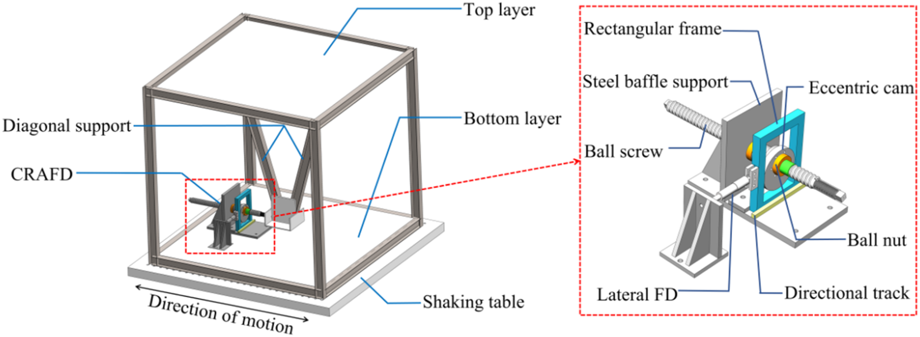
There was a V-shape diagonal support installed at the top of the frame to provide connection between the ground and the frame. In the uncontrolled steel frame, the V-shape support was separated from the ground. Besides, this test included a bolt-slotted friction damper (FD) and the CRAFD device, which connected the terminal of the V-shape support and the ground. The CRAFD, as shown in Figure 1, consisted of a cam-type response amplification (CRA) device and a lateral FD. The CRA device comprised a ball screw, ball nut, eccentric cam, rectangular frame, horizontal slide rail, and steel plate support. The eccentric cam had a mass of 1.8 kg, and the lateral FD has a design friction force of 1.2 kN. In contrast, the bolt-slotted FD, as the counterpart of the CRAFD, has a design friction force of 12 kN as the CRAFD could significantly amplify the friction force. Figure 2 shows the picture of the single-layer steel frame model and the CRAFD device used in this test. Test structure and physical image of CRAFD.
Sensors arrangement and test scenarios
The acceleration, displacement, force and strain responses were measured during the test. Figure 3 shows the configuration of the sensors. There were an accelerator and a displacement meter at both the top and bottom of the test model, as well as at the terminal of the V-shape support. In addition, a force sensor was installed in series with the dampers to measure the axial force in the dampers. A total of 12 strain gauges were installed on the columns and beams of the frame structure to measure the bending moment responses. Particularly, the strain gauges were installed on the V-shape support to identify the potential bending moment on the diagonal components. Sensors arrangement on the steel frame.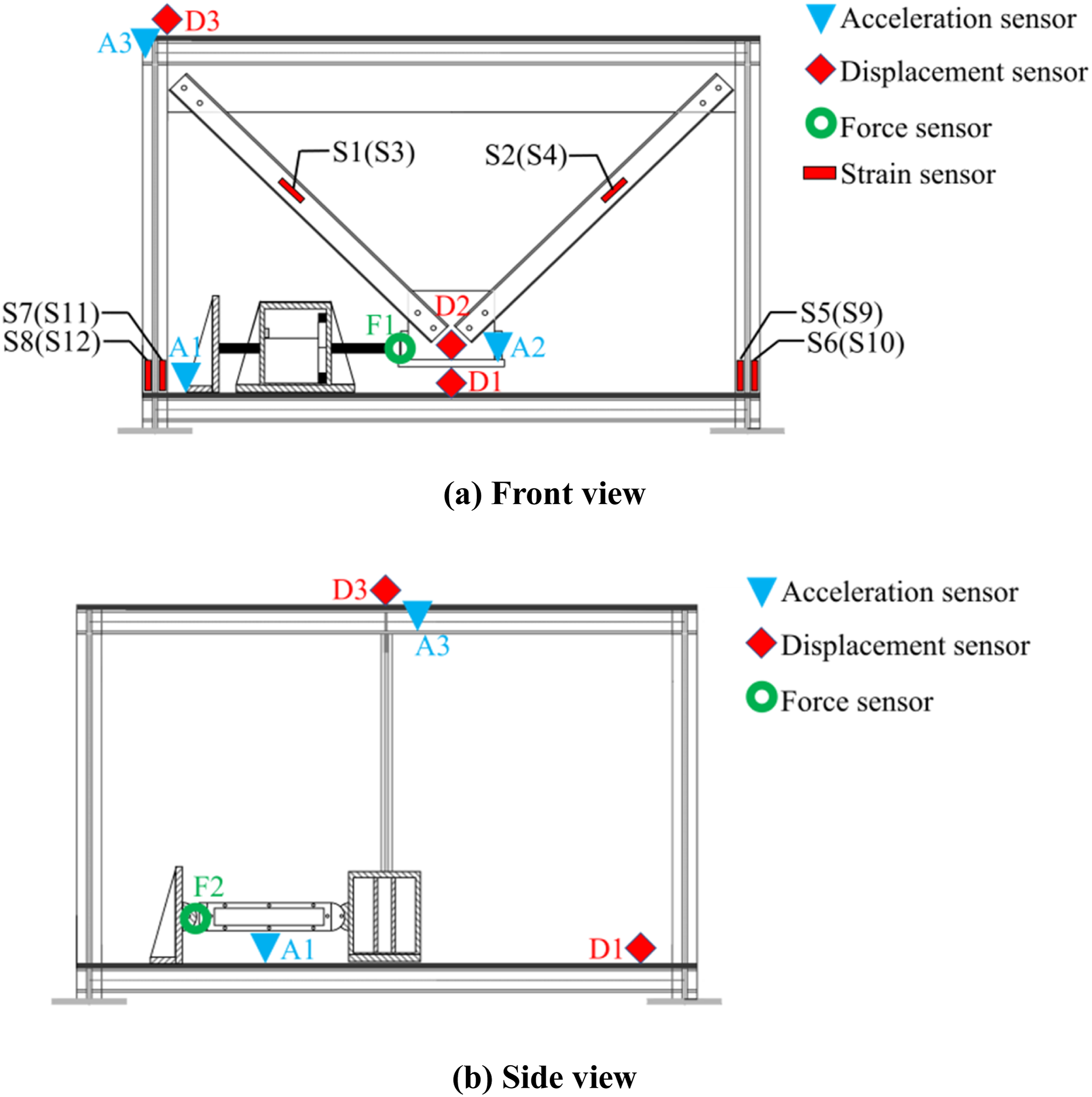
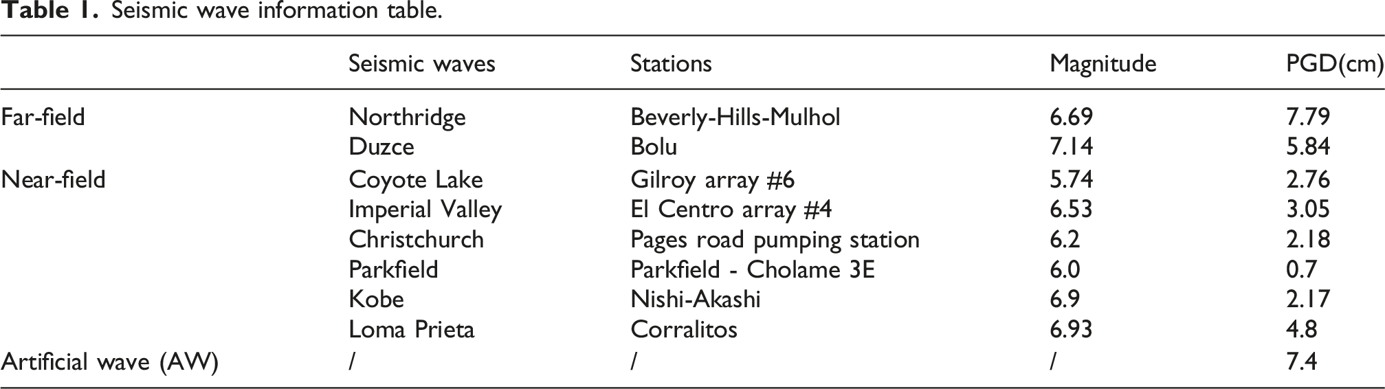
Seismic wave information table.
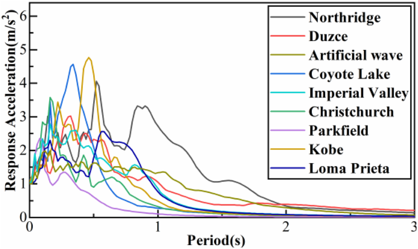
Acceleration response spectra of seismic records (PGA = 1 m/s2, damping ratio 5%).
Dynamic behaviors of CRAFD device under seismic loading
Frequency reduction effect
To investigate the dynamic behaviors of the CRAFD, the natural frequency of the frame model was identified under both uncontrolled and controlled conditions. Figure 5 compares the Fourier Spectrum of the acceleration response at A1 of the original, FD and CRAFD model before and after the seismic inputs. The acceleration response seems to has little change after the seismic inputs, as the steel frame and the dampers have little damage. The original, FD and CRAFD model have the natural frequency of 2.9, 4.0 and 5.5 Hz, respectively, and the damped model even has higher natural frequency than the uncontrolled model. As the white noise input only has a PGA of 0.05 g, the FD should not slide and keeps at the sticked status. Therefore, the supplementary stiffness provided by the FD increases the natural frequency of the model under the small white noise input. The supplementary stiffness of the damper in static is beneficial for the structure, helping to protect the structure under wind and service loads. As a comparison, the CRAFD increases the natural frequency more significantly than the FD. The higher static stiffness of the CRAFD arises from the ball-screw pair, which amplifies both the friction force and the axial stiffness. Therefore, from the point of view of normal service condition, the CRAFD shows the advantage over the conventional FD due to the high static stiffness. Fourier Spectrum of acceleration response under white noise inputs.
When the frame is subject to seismic loads, the dampers started to show nonlinearity, and the detected frequency decreases accordingly. Figure 6 shows the identified natural frequencies of the uncontrolled and damped model under various seismic records with PGA = 0.2 g, 0.3 g, and 0.4 g. Under small PGAs, the model with FD and CRAFD both have larger natural frequency than the uncontrolled model. Meanwhile, when the PGA increases, the FD and CRAFD starts to work and the equivalent frequency decreases. Particularly, the CRAFD under 0.4 g seismic inputs always has the lowest equivalent frequency, showing the effect of the negative stiffness resulting from the amplified inertial mass. CRAFD consists of a Cam-type Response -Amplification device (CRA) and a Lateral Friction Damper (Lateral FD). The most important component in CRA is the cam-type inerter, which inherently possesses a dynamic negative stiffness mechanical effect. Therefore, CRAFD can achieve a negative stiffness effect. Under the Northridge record, as an instance, the natural frequency of the uncontrolled model keeps around 2.9 Hz although the PGA varies. Meanwhile, the equivalent natural frequency of the FD model reaches 4.10 Hz when PGA is 0.2 g, and decreases sharply to around 3.1 Hz when PGA is over 0.3 g. Although the frequency of the FD model decreases, it is still larger than that of the uncontrolled model. Identified frequency of the steel frame model.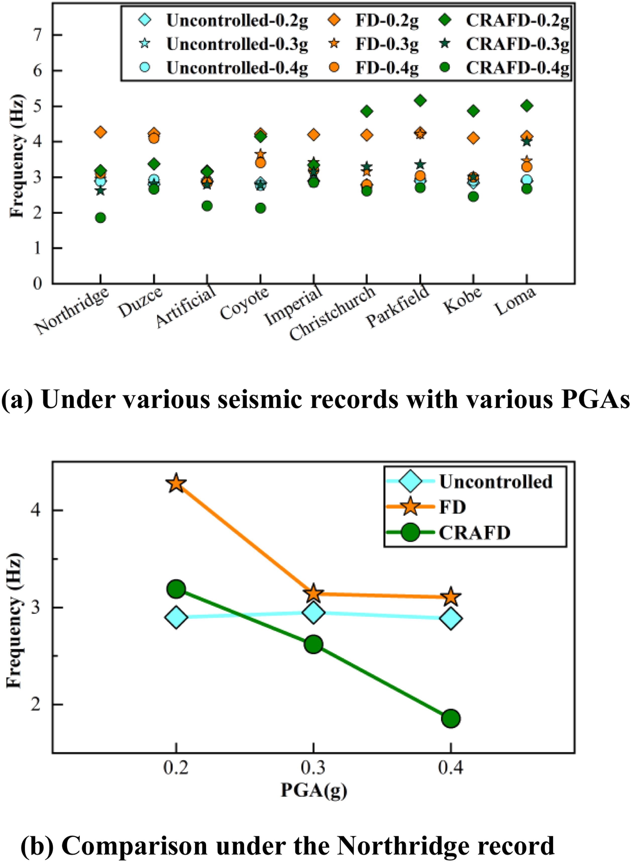
When the CRAFD model is subject to small white noise input, its identified frequency is higher than the FD model. Meanwhile, when a seismic record with PGA of 0.2 g is used, the identified frequency of the CRAFD is only 3.2 Hz, already smaller than the FD model. The significant decreased frequency shows that although the CRAFD has a larger initial stiffness, it is easier to start to work under seismic inputs than the FD. The magnitude of friction force provided by FD is positively correlated with the preload force of the damper, and the greater the preload force, the more difficult it is for the FD to maintain a sliding state. The design friction force of the traditional FD in this test is 12 kN, while the design friction force of the lateral FD in CRAFD is 1.2 kN. Therefore, CRAFD is easier to maintain a sliding state compared to traditional FD. In addition, as the PGA increases to 0.4 g, the equivalent frequency decreases to 1.91 Hz, even smaller than that of the uncontrolled model. The test results confirm the frequency reduction effect of the CRAFD under seismic inputs, even the device is subject to high-speed motions.
Friction amplification effect
Apart from the supplementary mass resulting from the inter part of the CRAFD, the amplified friction force is another key feature of the device. The total reaction force of the CRAFD, which consists of both friction and inerter components, was measured using force sensors. The inerter force can be estimated using the mass and relative acceleration between the V-shape support and the ground. Therefore, the friction part of the CRAFD is the difference between the measured force and the inerter force. Figure 7(a) compares the friction force time history of CRAFD and the lateral FD under the Northridge record. The design friction force of the lateral FD is 1.2 kN, while the friction force provided by the CRAFD reaches 8 kN, several times larger than that of the lateral FD. The lateral FD only occasionally reaches the sliding force as the seismic input is only 0.2 g. As shown in Figure 7(b), when the PGA increases to 0.4 g, under which the FD slides frequently, and the CRAFD still shows significant amplified friction force. More importantly, the maximum amplified friction force of the CRAFD stays around 8 kN under various PGAs, which can prevent too large friction force in the device. Friction force time history of the lateral FD and CRAFD.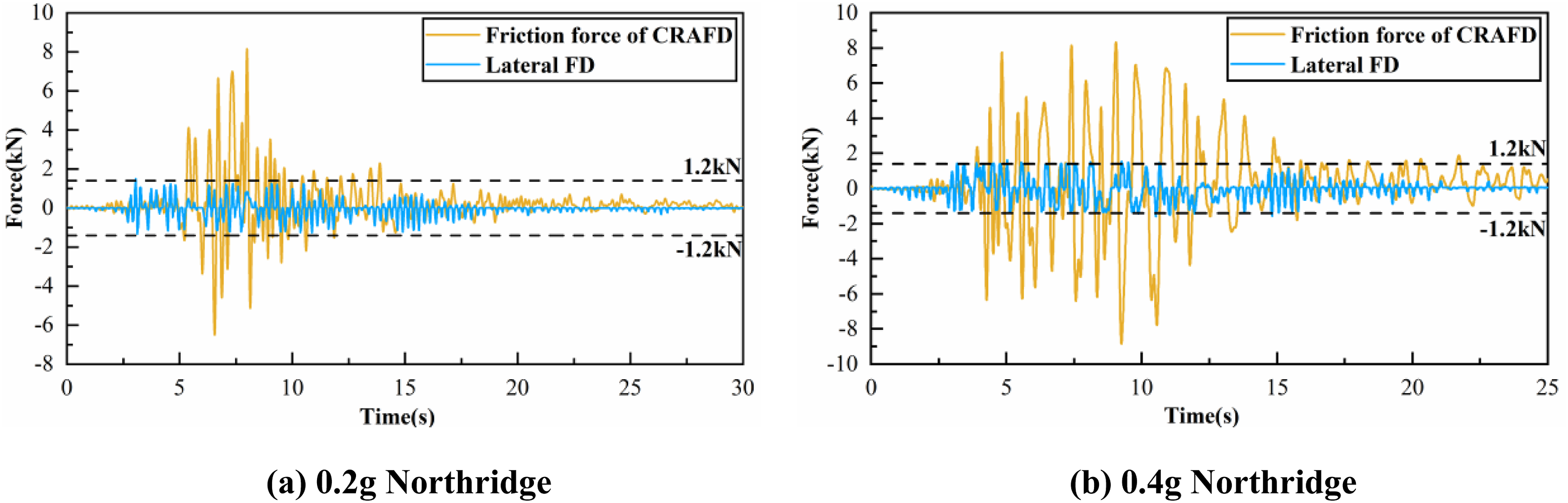
As the CRAFD generates friction and inertial forces, Figure 8 compares the time history curves of the friction and inertial forces. Under the 0.2 g Northridge record, the inertial force provided by the CRA device is slightly higher than the friction force. Under the 0.4 g Northridge record, the inertial force of the CRA device generates up to 15 kN forces under seismic inputs. As a result, the CRAFD is able to generate significant negative stiffness, while the friction force stays around 8 kN. The force time history conforms the reliability of the ball-screw pair in the CRAFD under severe earthquake events, as the device and reduces the natural frequency of the damped structure, which is consistent with the results in Figure 6. Time history curves of force, total friction force and inertia force of CRAFD.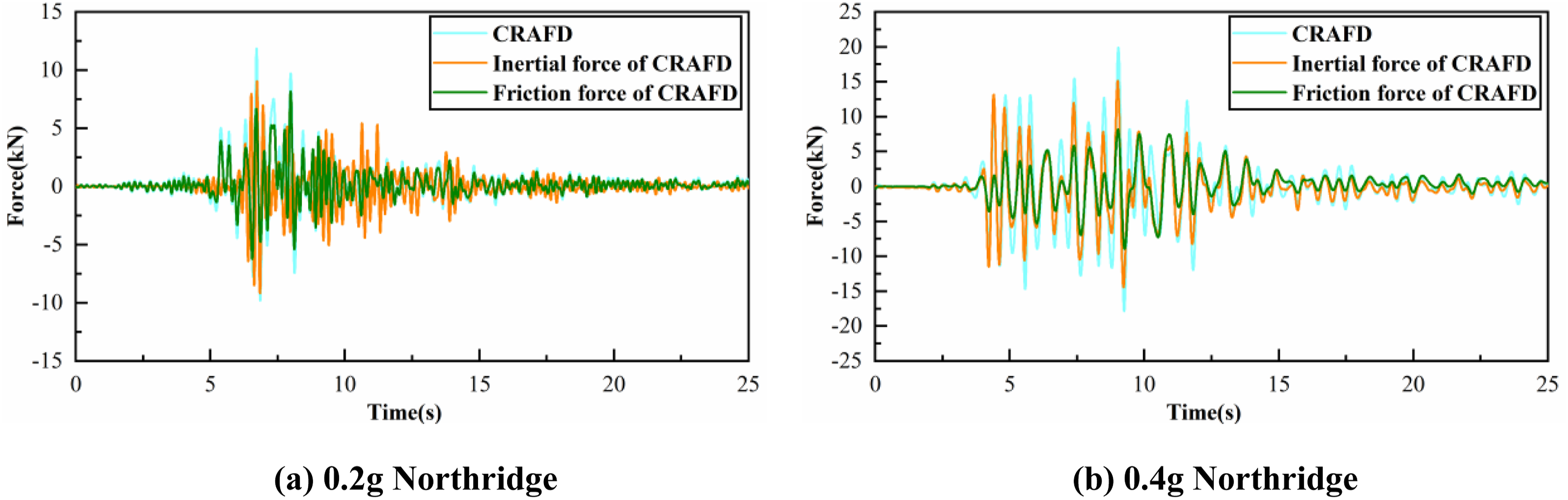
The inertial force of the steel frame under seismic inputs is shared by the four columns and the supplementary damper. As shown in Figure 9, due to the huge amplified friction force of the CRAFD, the damper shares around half of the inertial shear force, and significantly reduces the bending moment at the columns. As a comparison, the FD only generates much smaller friction force than the CRAFD, the shear force on the columns is much larger. CRAFD response under near fault record (Loma Prieta record).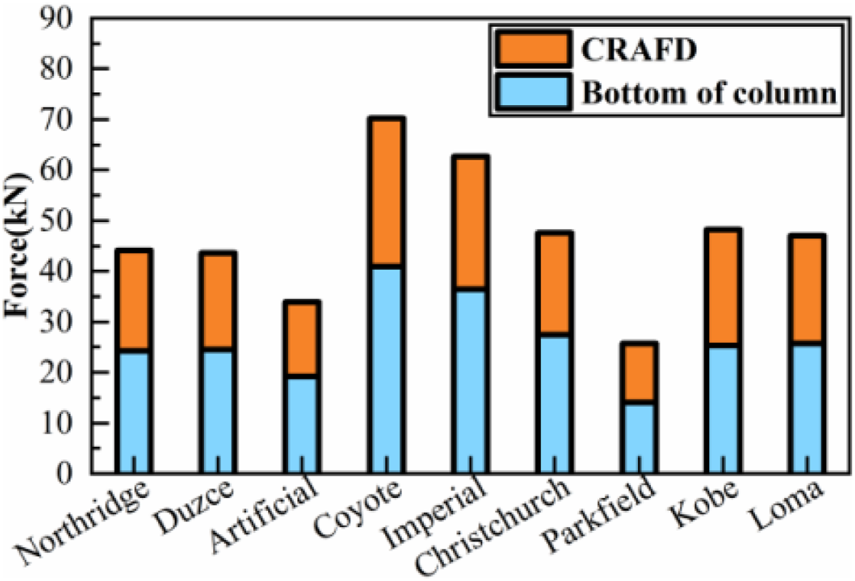
The near fault seismic input generally has a pulse-like component, challenging the reliability of the inerter-based dampers. In this test, several near-fault record, like the Imperial Valley and Loma Prieta records, have pulse-like components. As shown in Figure 10, the force response and the seismic input shows that the CRAFD reaches the maximum force at the pulse, and the device can sustain the performance even under the near-fault earthquakes. CRAFD reaction forces under near fault record (Loma Prieta record).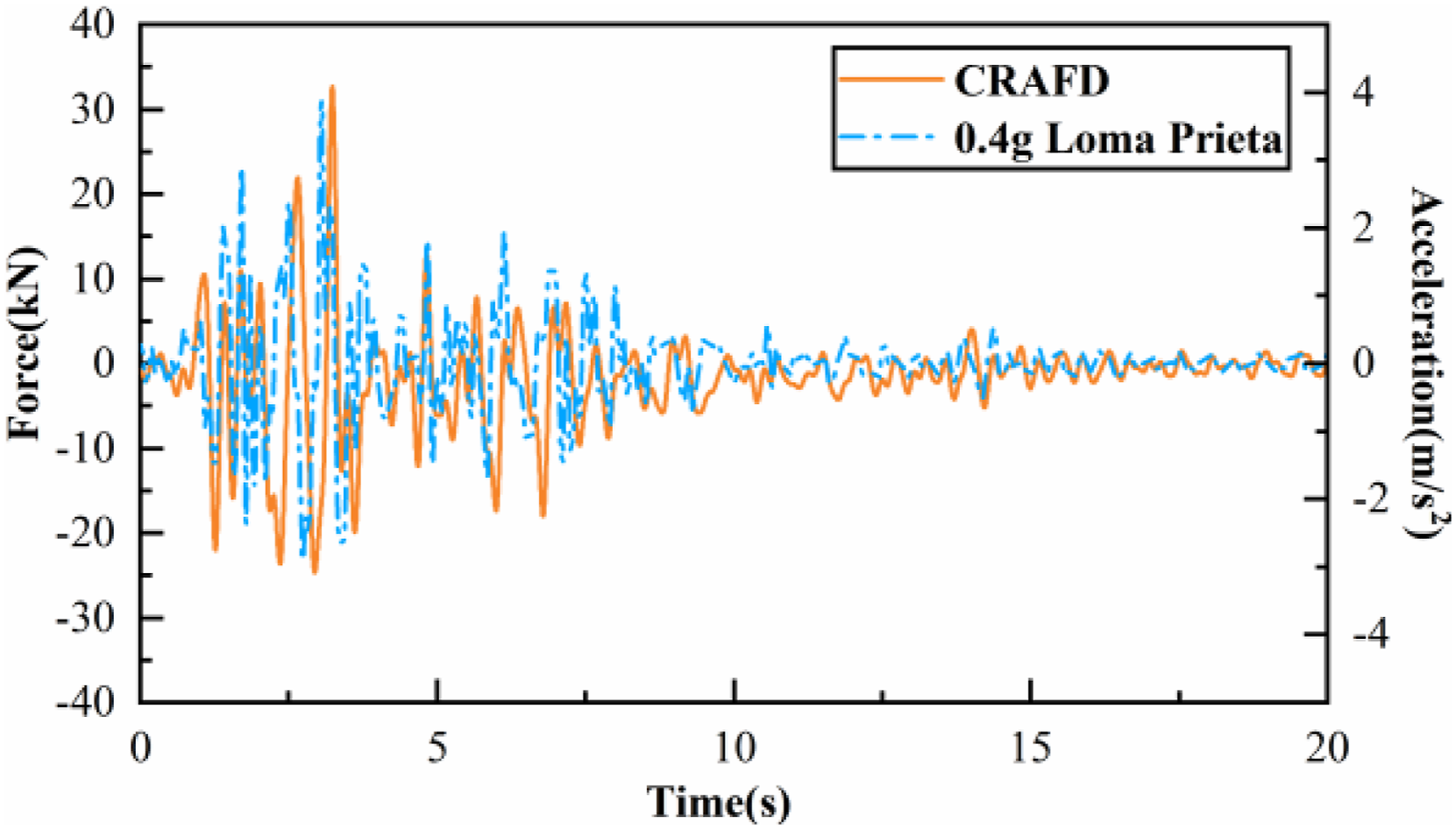
In summary, during the test, the CRAFD shows both the amplification of friction force and frequency reduction due to the inerter effect under the seismic inputs, which are predicted by the theoretical study. More importantly, the device performed reliably under high-velocity motion, validating its ability in seismic events.
Effect of the CRAFD on seismic responses mitigation
Seismic protection principle of the CRAFD based on test data
The CRAFD shows reliability under high speed motions, while its effect on reducing seismic responses is another concern. During the seismic test, the three models, including the original, FD and CRAFD model, are subject to the nine seismic records with various PGAs ranging from 0.2 g to 0.4 g.
Figure 11 compares the peak displacement at the top of the model under all seismic records, as the inter-story drift is the key seismic response for buildings. Under all the seismic inputs, the FD can slightly reduce the peak displacement response, while the CRAFD can further reduce the response by a larger margin. Under PGA = 0.2 g, 0.3 g and 0.4 g, CRAFD reduced the peak displacement by an average of 60.51%, 62.74% and 66.18% respectively, significantly outperforming the FD’s 37.26%, 41.71% and 41.07% reduction respectively. The CRAFD shows significant advantages on reducing the displacement response compared with the FD. Comparison of peak displacement response.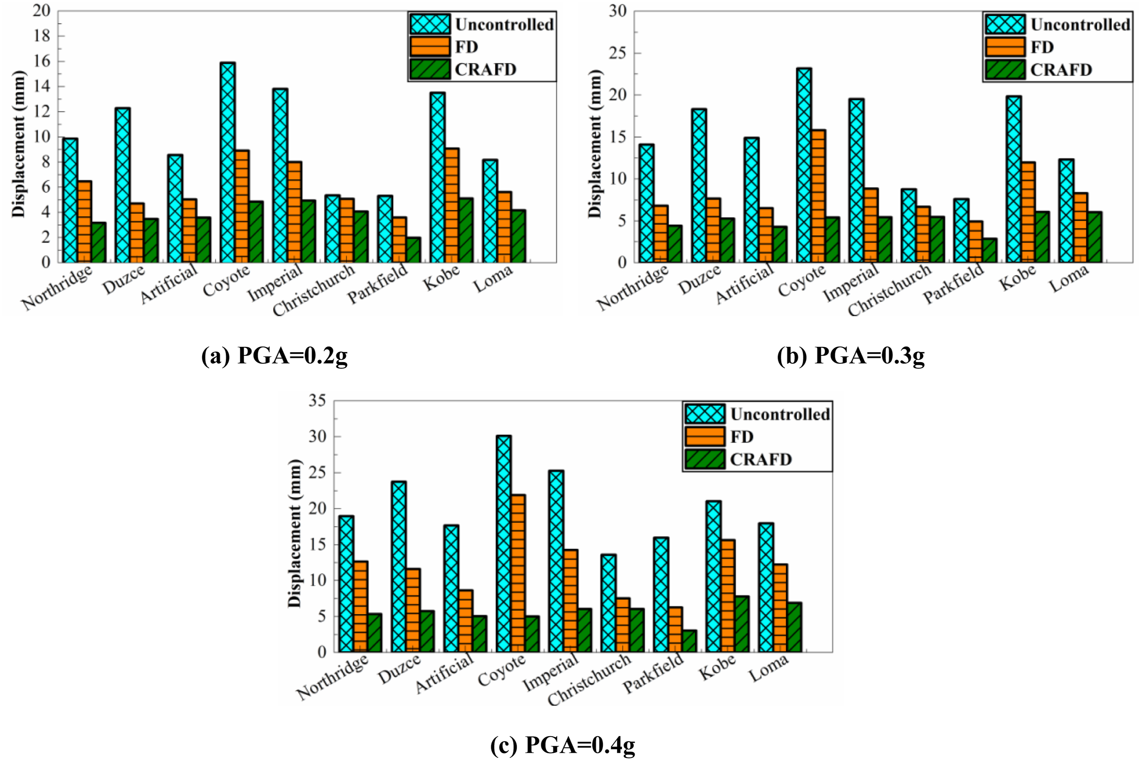
Figure 12 shows the time history curve and the corresponding frequency response function (FRF) of displacement response under the Northridge record with a PGA of 0.4 g. According to the time history curves, the FD and CRAFD both can significantly reduce the displacement response. Meanwhile, the FD model introduces notable high-frequency components, attributed to the frequent stick–slip behavior of the FD under seismic excitation. More importantly, the model with the CRAFD generates more low frequency responses around 2 Hz, compared with the FD, showing the frequency reduction effect of the CRAFD. Displacement response of the three models under 0.4 g Northridge record.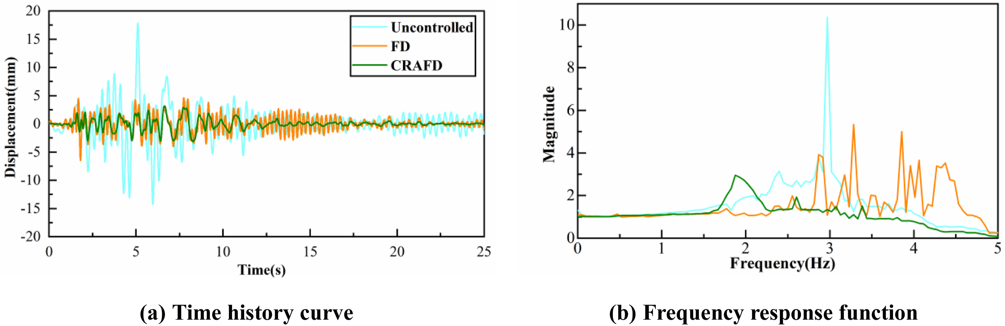
Generally, the displacement of a structure with low frequency is prone to generate large displacement response, the CRAFD shows the contrast results. Since the displacement response is usually governed by a single modal, the displacement time history can be fitted using a single-degree-of-freedom system with specified natural frequency and damping ratio. Figure 13 shows the fitted damping ratios of the original, FD and CRAFD models under various seismic inputs. The uncontrolled model is made of steel with welded connection, so it has a low damping ratio when no damper is installed. After the FD and CRAFD are installed, the damping ratio significantly increases as the dampers provide supplementary energy dissipation. Particularly, the damping ratios under 0.2 g seismic inputs are relatively small, only around 10% for both the two kinds of dampers. Meanwhile, when PGA increases to 0.4 g, the damping ratio sharply increases as the dampers slide frequently. Notably, under all seismic inputs, the CRAFD results in larger damping ratios than the FD, and that’s why the CRAFD achieve better effectiveness on reducing the displacement response. Identified structural modal damping ratios.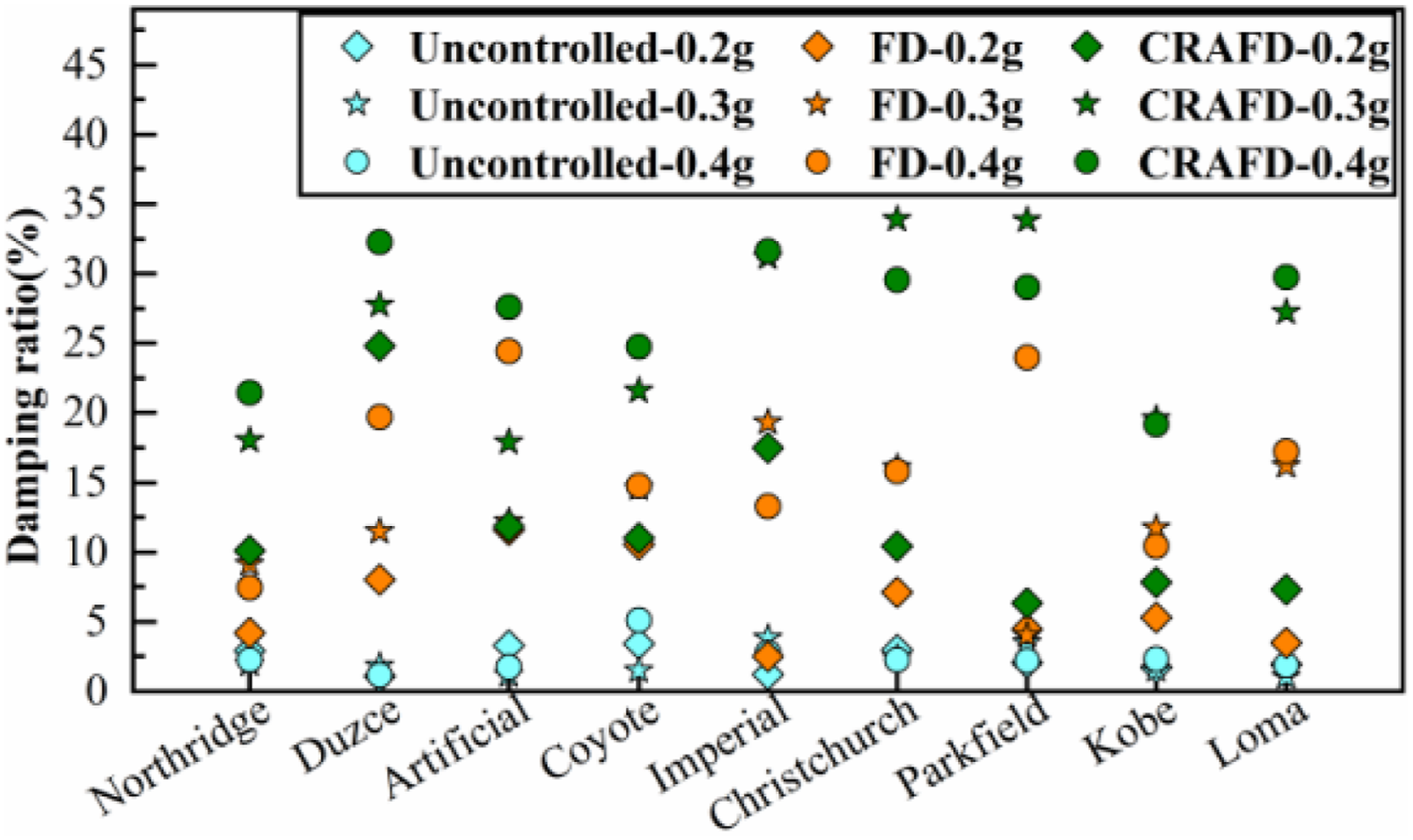
Effect of the CRAFD on reducing seismic responses: Spectral and energy view
The acceleration response relates to the inertial force on the structure, so reducing the acceleration response is the primary way to reduce the seismic responses. As shown in Figure 14, the uncontrolled model generates significant acceleration response, due to the small damping ratio. When the FD is installed, FD reduced the peak acceleration by an average of 5.12%, 9.89% and 15.78% respectively under PGA = 0.2 g, 0.3 g and 0.4 g. Meanwhile, the CRAFD can further reduce the acceleration response, reaching a mitigation rate at 9.51%, 15.67% and 23.25% in average respectively under 0.2 g, 0.3 g and 0.4 g inputs. When the PGA is small, the reduction ratio is small as the FD and CRAFD are hard to slide. Particularly, under all the seismic records, the CRAFD shows better performance than the FD. Besides, when the acceleration response is larger, the CRAFD shows larger mitigation rate, as the sliding in the device prevent high acceleration response. Comparison of peak acceleration under various seismic inputs.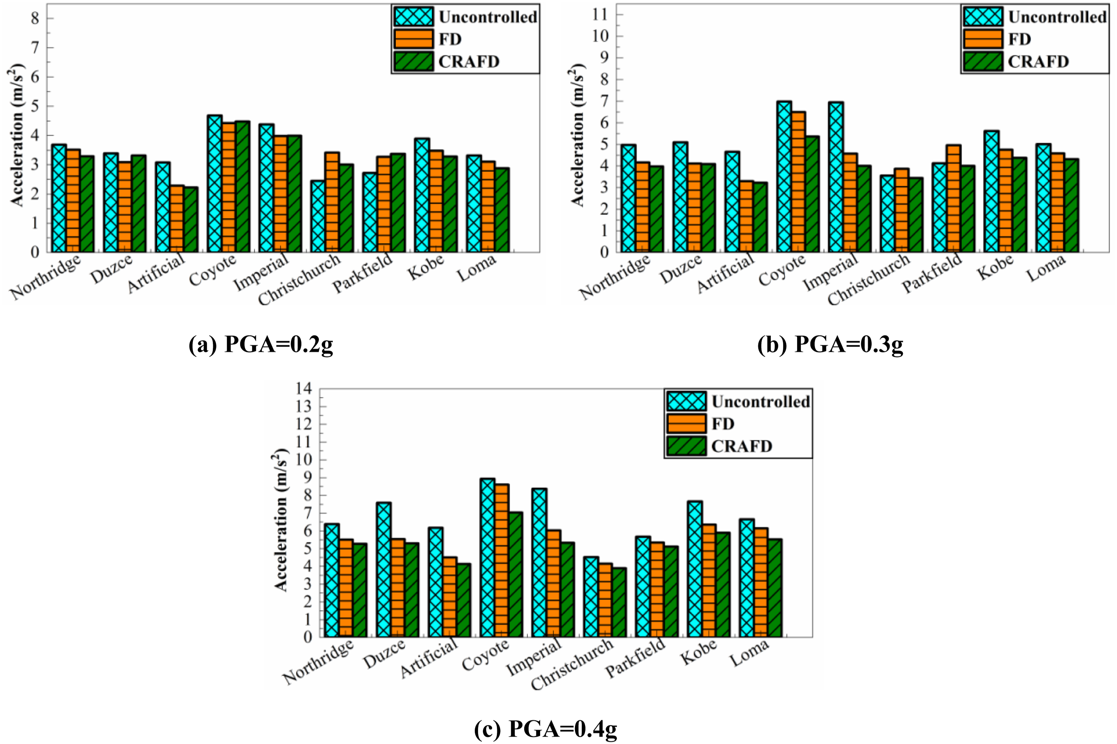
Sliding of friction dampers is the key point in reducing the peak acceleration response. As shown in Figure 15(a), at the beginning of the seismic event, the FD model generates larger acceleration than the uncontrolled one, indicating the FD in the stuck status increases the frequency and the acceleration response. Meanwhile, the CRAFD model, due to the negative stiffness resulting from the inerter, generates smaller acceleration than the FD model. When the CRAFD starts to work, it decreases the frequency and increases the damping ratio. As shown in Figure 15(b), compared with the uncontrolled model, the FD model although significantly reduces the response near 3 Hz, amplifies the response in higher frequency range, as the stuck status increases the stiffness. Meanwhile, the CRAFD reduces the high frequency and 3 Hz components at the same time, and the low frequency components governs the response. Therefore, the CRAFD has its distinctive advantages on reducing the acceleration response. Comparison of structural acceleration response under 0.4 g Northridge.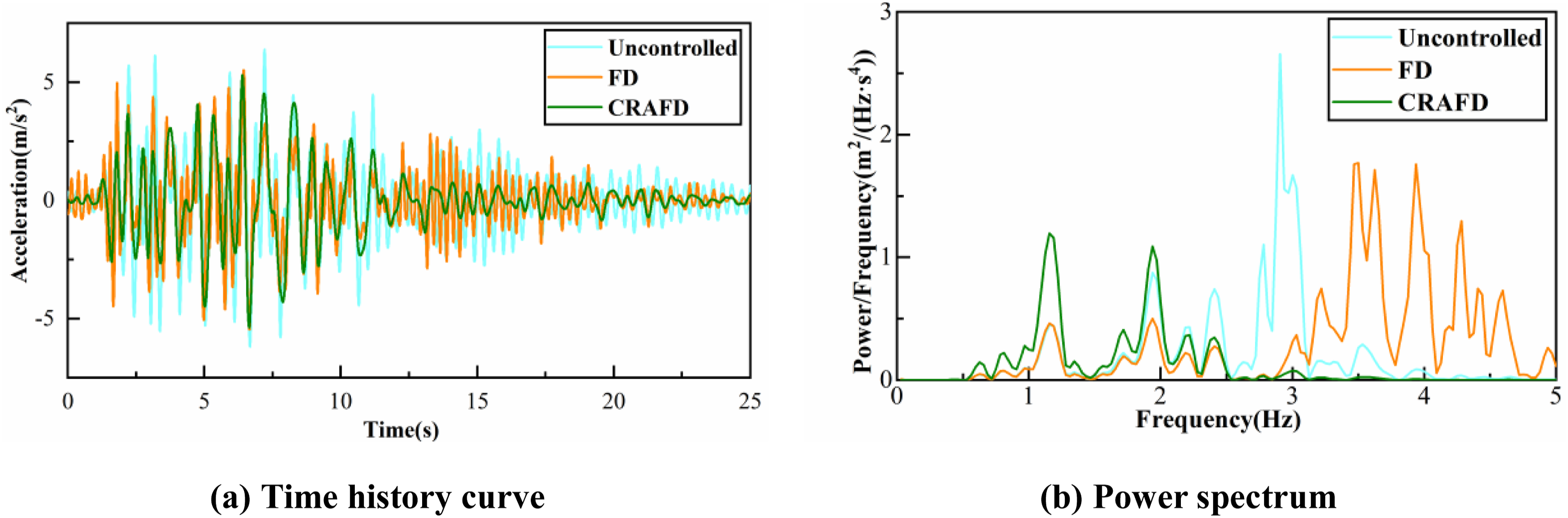
To further investigate the influence of the CRAFD on the primary structure, the wavelet spectra of acceleration response at A3 point are plotted. As shown in Figure 16(a) and (b), although the seismic input primarily compromises 1–2 Hz components, the uncontrolled model generates significant 1–5 Hz acceleration responses. In the FD model, as shown in Figure 16(c), although the spectrum density decreases, the model generates high frequency components around 5 Hz. Particularly, after the seismic input ends, the FD model still generates 5 Hz responses during the attenuation segment. As a comparison, as shown in Figure 16(d), the CRAFD model not only achieves a substantial reduction in spectral density but also confines the response to a lower frequency range of 1–3 Hz. Furthermore, following the end of seismic excitation, the acceleration responses of the CRAFD model attenuate rapidly. Once the CRAFD enters its working state, it simultaneously reduces the structural frequency—thereby lowering the acceleration response—and increases the damping ratio, which accelerates response decay. These observations are consistent with the findings presented in Figure 15. Acceleration wavelet spectrum under 0.4 g Northridge.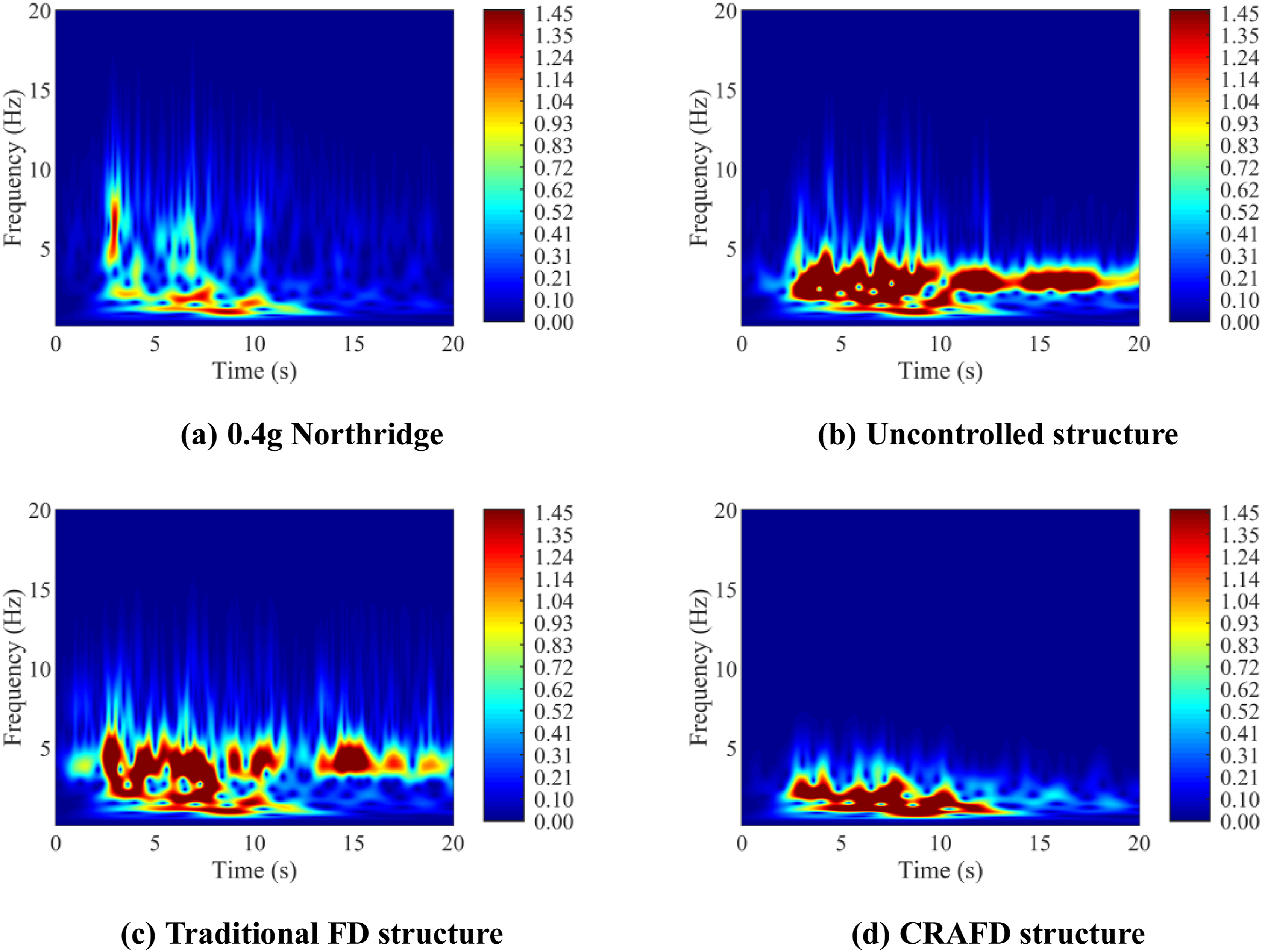
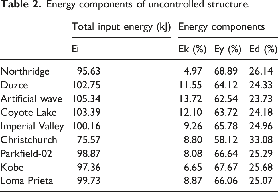
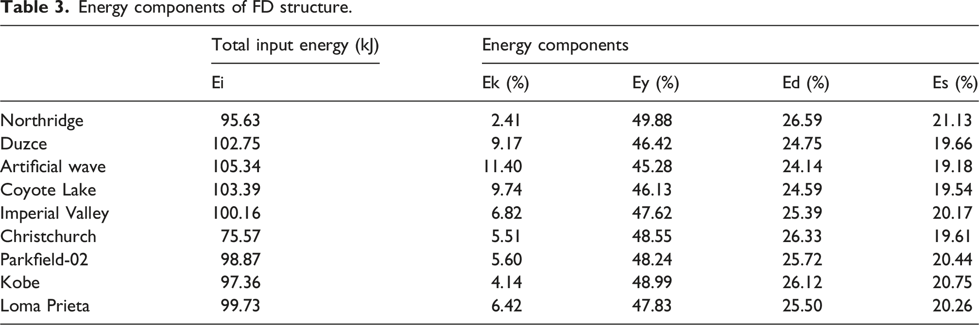
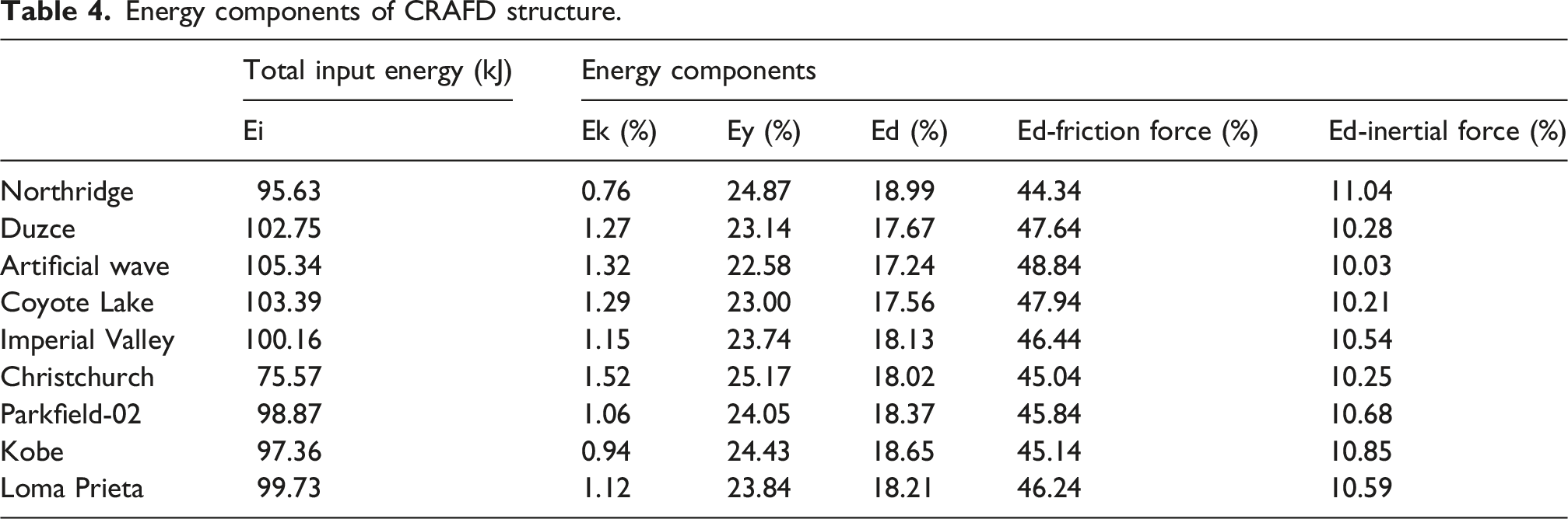
Figure 17 shows the energy time history of the three structures under 0.4 g Northridge record, and Tables 2–4 show the proportion of input energy for each part under 0.4 g various records. Ei is the seismic input energy, Ek and Ey are the kinetic and strain energy of the structure, respectively. Ed, Es, Es-friction force and Es-inertial force represent the energy dissipation of the structure, traditional FD, CRAFD friction force and inertial force, respectively. When there is no supplementary dampers to dissipate the seismic energy, the input energy is absorbed by the primary structure itself. Although the traditional FD is installed, the strain energy of the structure Ey still accounts for the highest proportion, the damping energy dissipation by the damper Es is even lower than that of the structure Ed. The curve of Es seldom fluctuates, as the traditional FD is easy to stick when the external force is not large enough. As a comparison, the negative stiffness and frequency reduction effect of CRAFD improve the energy dissipation ratio, and reduce the overall dynamic response of the structure accordingly. Although the inertia force of CRAFD is large, its main role is to provide negative stiffness effect, and the energy dissipation effect is relatively small. At the same time, due to the friction amplification effect of CRAFD, the total friction energy dissipation of CRAFD is much higher than the structural strain energy, which is the primary form of energy dissipation. Therefore, it can significantly reduce the dynamic response of the structure, thereby protecting the structure from damage or destruction caused by ground motion. Time history curve of structural input energy under 0.4 g Northridge. Energy components of uncontrolled structure. Energy components of FD structure. Energy components of CRAFD structure.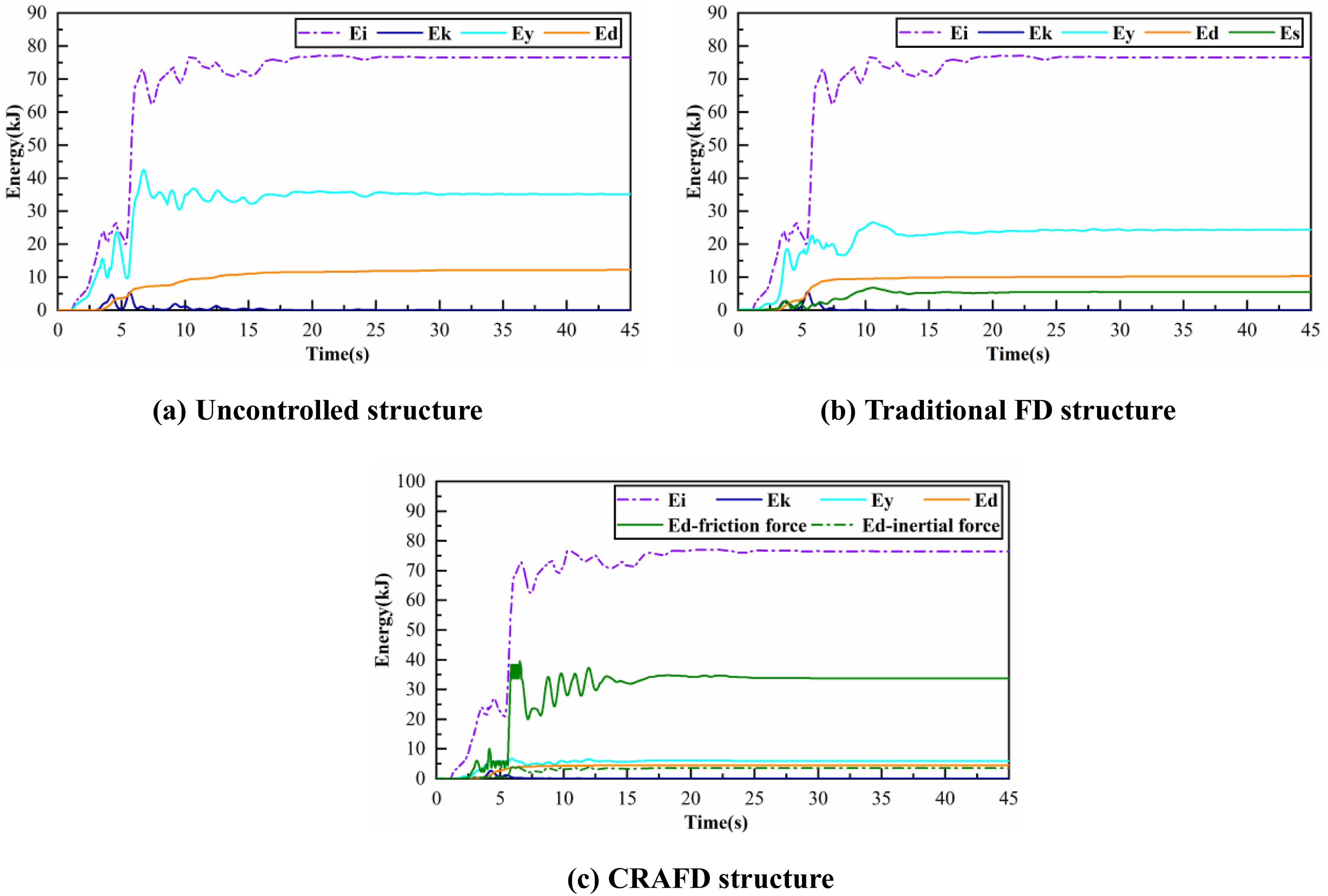
Seismic protection of the primary structure by the CRAFD
Figure 18 shows the strain time history curve of the column root section (S9) under 0.4 g Coyote Lake record, and Figure 19 compares the peak strain under Coyote Lake with various PGAs. When the FD is installed, the structure still generates significant high frequency responses around 3 Hz shown in Figure 18(b), which results in large strain response as shown in Figure 18(a). As the PGA reaches 0.4 g, the FD remains in a slipping state more frequently than in a stuck state, as evidenced by the reduced 4 Hz components in Figure 18(b). In contrast, the CRAFD further reduces the strain response, particularly in the frequency range near the natural frequency of the primary structure (around 3 Hz). The CRAFD not only mitigates acceleration and displacement responses but also substantially reduces strain responses, thereby providing enhanced protection to the primary structure. In addition, the CRAFD makes the root mean square (RMS) of the strain response smaller than that under FD, which also helps to prevent structure damage under seismic events. Strain responses at the root section of the column under 0.4 g Coyote Lake record. Peak strain of structural column base under Coyote Lake.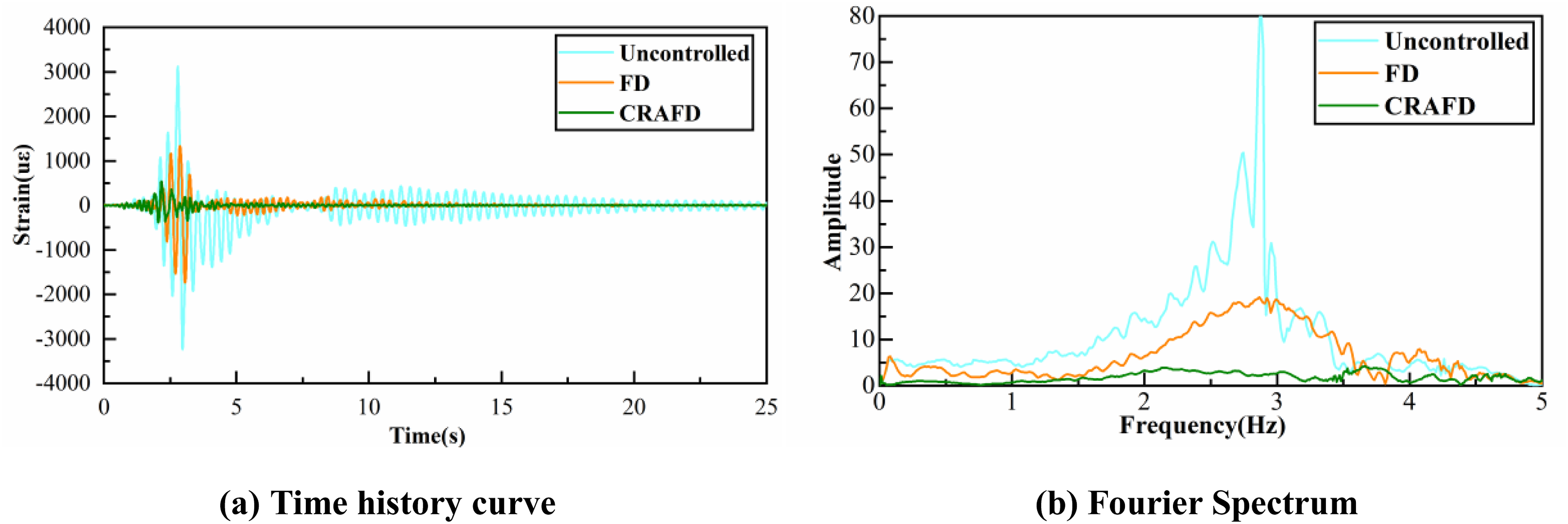
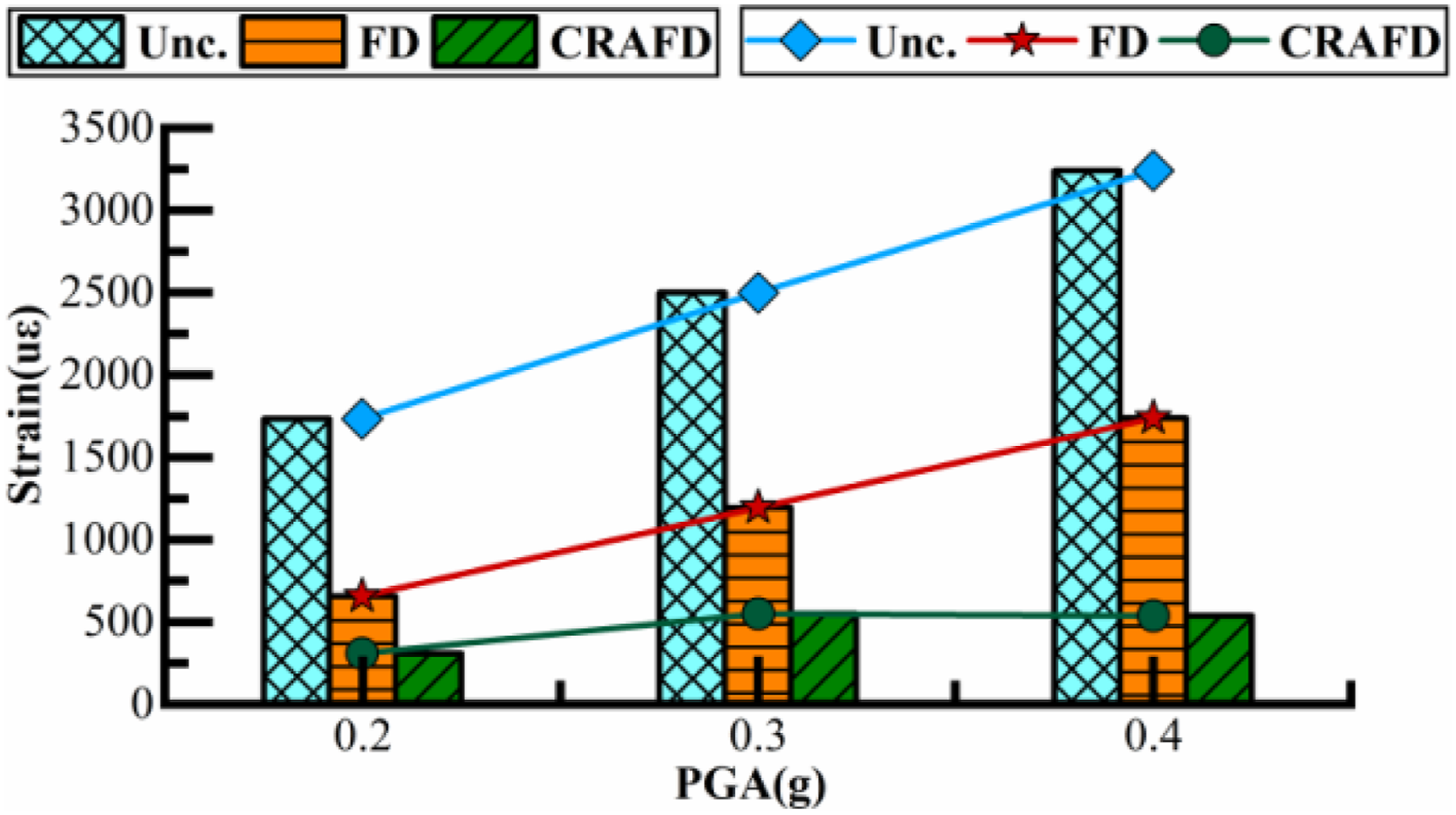
As shown in Figure 19, the peak strain response of the uncontrolled structure and the FD damped increases approximately linearly with the PGA under the Coyote Lake record. The FD demonstrates a consistent and stable mitigation effect on the structural response. In comparison, the CRAFD achieves a further reduction in strain response relative to the FD, and more importantly, exhibits greater effectiveness under stronger ground motions. Particularly, the structure with CRAFD generates similar peak strain response under 0.3 and 0.4 g, showing the CRAFD is more effective under extreme seismic events.
Although the test model is symmetric in geometry, the supplementary FD and CRAFD may introduces out-of-plane deformation of the V-shape link. Figure 20 shows the peak strain at two sides of the two components of the V-shape link under the Coyote Lake record. When the damper is absent, the V-shape link still generates slight bending moments, as the test model has torsional motion under the uniaxial seismic input. When the FD is installed, there is still considerable bending moment at the V-shape link, as the strain responses at the two sides of the components are different. As a comparison, when the CRAFD is installed, the difference between the strain response, which reflects the bending moment response at the V-shape link, is only 4% and is much smaller than that with the FD. CRAFD includes rectangular frame, directional track, and lateral FD, all of which exert out-of-plane constraints on the V-shaped link, so CRAFD can suppress the out-of-plane deformation of the V-shaped link. Therefore, the CRAFD helps to improve the stability of the V-shape link, as the small bending moment helps to increase the allowable compression loads. Peak strain of structural slant supports under Coyote Lake record with various PGA.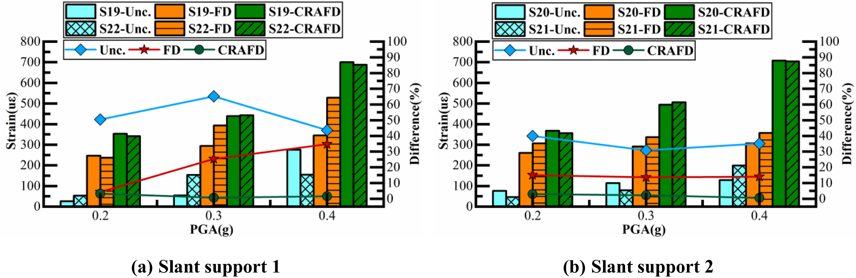
Conclusions
In this study, the real-world performance of the CRAFD on reducing seismic responses is investigated. The dynamic behavior of the CRAFD under high-speed loads and the effect of the CRAFD on the primary structure are illustrated. Based on the experimental findings, following conclusions are drawn. (1) Under dynamic seismic loads, the CRAFD achieves the design objectives of significant amplified friction and inertial mass effects, resulting in huge friction force and negative stiffness on the primary structure. Additionally, CRAFD maintains functionality even under high-speed pulses-like motion during the near-fault seismic inputs; (2) Due to the friction force amplification effect, CRAFD exhibits significant advantages in energy dissipation, resulting in a superior seismic reduction effect on displacement response compared to traditional FD. The inertial mass effect of CRAFD notably lowers the overall structural frequency, enhancing the seismic reduction effect on acceleration response. As a result, the CRAFD increases the equivalent damping ratio of the whole system; (3) CRAFD is more likely to stay in sliding status than the traditional FD, enhancing its ability to prevent structural damage; (4) Due to CRAFD’s energy dissipation capacity, the input energy of the seismic input into the structure is significantly reduced, leading to decrease in strain responses, and the reduction rates increases with the PGA. In addition, the V-shape link generates smaller bending moment response with the CRAFD than the FD, the CRAFD prevents the out-of-plane deformation of the link.
CRAFD has a relatively simple construct, low construction cost in practical engineering, reliable mechanical properties, and good application prospects. The research in this paper focuses only on single-layer structure and unidirectional seismic input. In the future, test research on multi-layer structure and multi-directional seismic input of CRAFD will be conducted to further explore the mechanical mechanism of CRAFD and the seismic reduction mechanism of the structure.
Footnotes
Acknowledgements
The authors are grateful for the financial support from the Natural Science Foundation of China (Grant Nos. 52378499, 52308488 and 52478502), the National Key Research and Development Project of China (Grant Nos. 2022YFC3801201), and Natural Science Foundation of Guangdong Province (Grant Nos. 2024A1515012788, 2023A1111120008, 2023A1515010072, 2022A1515110561) in this study.

Author contributions
Haoming Huang: Writing - original draft, Formal analysis, Visualization. Yuhong Ma: Conceptualization, Supervision, Funding acquisition, Resources. Guifeng Zhao: Conceptualization, Validation, Resources, Funding acquisition. Zhenyu Yang: Resources, Funding acquisition, Supervision, Validation, Writing - review & editing. Wei Liu: Supervision, Writing - review & editing. Zeming Liu: Conceptualization, Supervision.
Funding
The authors disclosed receipt of the following financial support for the research, authorship, and/or publication of this article: The authors are grateful for the financial support from the Natural Science Foundation of China (Grant Nos. 52378499, 52308488 and 52478502), the National Key Research and Development Project of China (Grant Nos. 2022YFC3801201), and Natural Science Foundation of Guangdong Province (Grant Nos. 2024A1515012788, 2023A1111120008, 2023A1515010072, 2022A1515110561) in this study.
Declaration of conflicting interests
The authors declared no potential conflicts of interest with respect to the research, authorship, and/or publication of this article.
Data Availability Statement
Some or all data (e.g. test data) and models that support the findings of this study are available from the corresponding author upon reasonable request.