
Abstract
An asymmetric stiffness structure, comprising a permanent magnet (PM) and an electromagnetic coil (EC), has been designed to create a vibration isolator with high-static-low-dynamic stiffness (HSLDS). The mathematical model of the system is established using the molecular current method and is compared with simulation results. Additionally, a nonlinear dynamic model of the single-degree-of-freedom vibration isolation system is developed. The influence of factors such as excitation and current on the displacement transmissibility of the system is analyzed using the incremental harmonic balance method (IHB). To validate the findings, an experimental test system is constructed. The results of the validation demonstrate that by adjusting the current in the EC, without altering the structural parameters of the system, the natural isolation frequency of the vibration isolation system can be reduced. This adjustment broadens the vibration isolation frequency band.
Introduction
In a vibration isolation system, effective isolation is achieved only when the external vibration frequency exceeds
Ledezma employed the suction force between PM as the negative stiffness, in conjunction with the positive stiffness provided by nylon wires, to develop a system with HSLDS (Ledezma-Ramirez et al., 2012; Ledezma & Luna, 2013). Similarly, Zhou et al. designed a magnetic spring mechanism utilizing two ECs and one PM, where the stiffness of the magnetic spring can be adjusted by adjusting the current magnitude and direction of the ECs (Zhou & Liu, 2010, 2011). However, these systems are currently restricted to horizontal installations due to structural constraints. To address this limitation, our research proposes an HSLDS isolator that utilizes PM and EC. The repulsive force between the PMs generates both positive and negative stiffness while also providing axial load-carrying capacity. By adjusting the current in the EC, it is possible to change the axial stiffness, thereby altering the initial isolation frequency.
Structure and Principle
A novel non-linear vibration isolation device with HSLDS characteristics is proposed. The structure consists of three ring-shaped PMs and two hollow ECs, as shown in Figure 1(a). The three PMs are arranged coaxially, with the two ECs positioned coaxially and in the same plane as their corresponding PMs. The PMs and ECs at both ends are rigidly connected to specific locations on the frame using connectors. The frame is then rigidly connected to the base. The PM located in the middle of the structure is connected to the shaft and moves back and forth along with it. Simultaneously, it is linked to a mass block via the shaft. The PM is situated within the EC, which contributes to reducing the overall dimensions of the structure. As shown in Figure 1(b), the thickness of the PM at the bottom is greater than that of the PMs at the top and middle sections. This design creates an upward magnetic gradient at the point of balance, corresponding to the load mass in this system. All PMs are magnetized axially, with neighboring PMs exhibiting opposite magnetization directions. The current polarity remains consistent in both ECs.
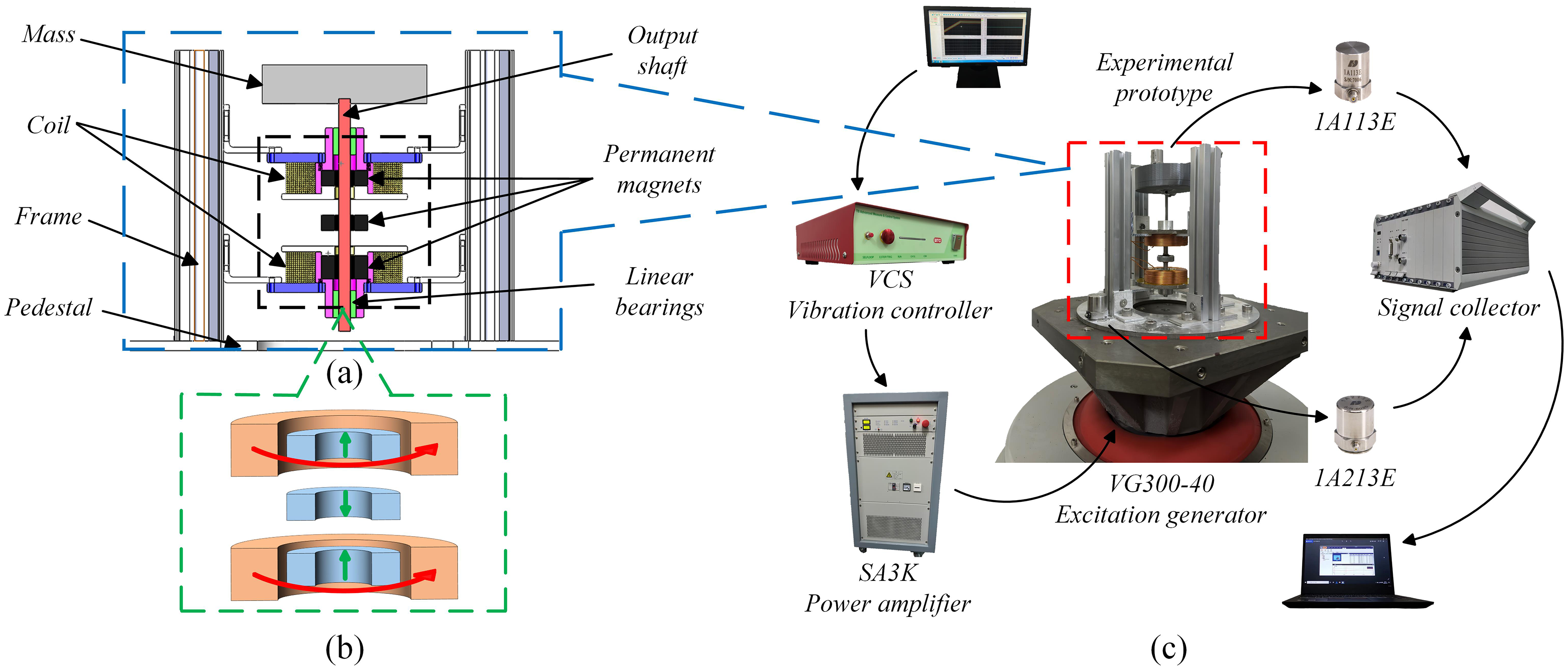
HSLDS vibration isolators. (a) System model. (b)Electromagnetic mechanism, The green and red arrows indicate the directions of magnetization and current polarity, respectively. (c) Experimental setup.
Mathematical Model
Axial Force
The molecular current method, which has been discussed in previous studies, is depicted in Figure 2(a) and (b). These figures present the theoretical model of the molecular current method for a pair of PM-PM and PM-EC in the system, respectively. In this model, the PM is represented by two internal and external surface currents with opposite current polarity, while the EC is represented by a superposition of multiple layers of surface currents with the same current polarity (Cooper et al., 1973; Robertson et al., 2011). The axial forces Fm1 and Fm2 between the PM-PM and the PM-EC can be determined based on the schematic diagram of the force between any ring currents on the surfaces of the two magnets, as shown in Figure 2(c).
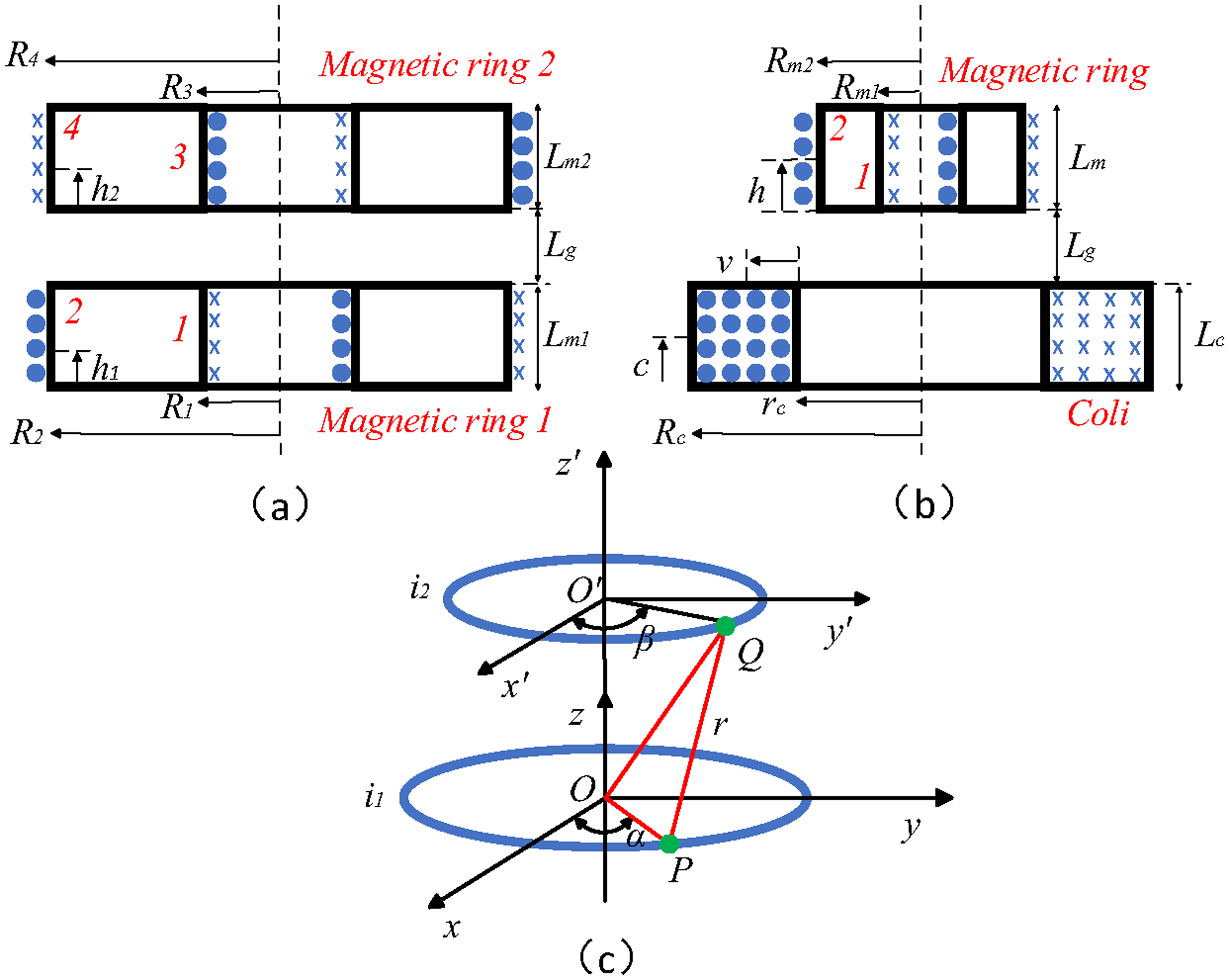
Molecular current modeling. (a)PM-PM. (b) PM-EC. (c) Interaction force between current loops.
This system can be viewed as a combination of two PM-PMs and PM-ECs. As a result, the axial forces Fm2 and Fc2 of the other pair can be obtained using the same reasoning. Therefore, the total axial force of the system is given by Fz = Fm1 + Fm2 + Fc1 + Fc2. Figure 3 shows the comparison between theoretical calculations and simulation results, showcasing a nonlinear relationship between axial force and displacement. This relationship is characterized by a gradual increase followed by a sharp rise, with axial force exhibiting asymmetry on both positive and negative sides of displacement. Therefore, the former corresponds to the high static-low dynamic stiffness characteristic of the vibration isolator, and the latter corresponds to the asymmetric stiffness structure of the same. The theoretical derivation is confirmed by the fact that the average error is less than 5%. Table 1 presents the structural parameters used in both the theoretical calculation and simulation.
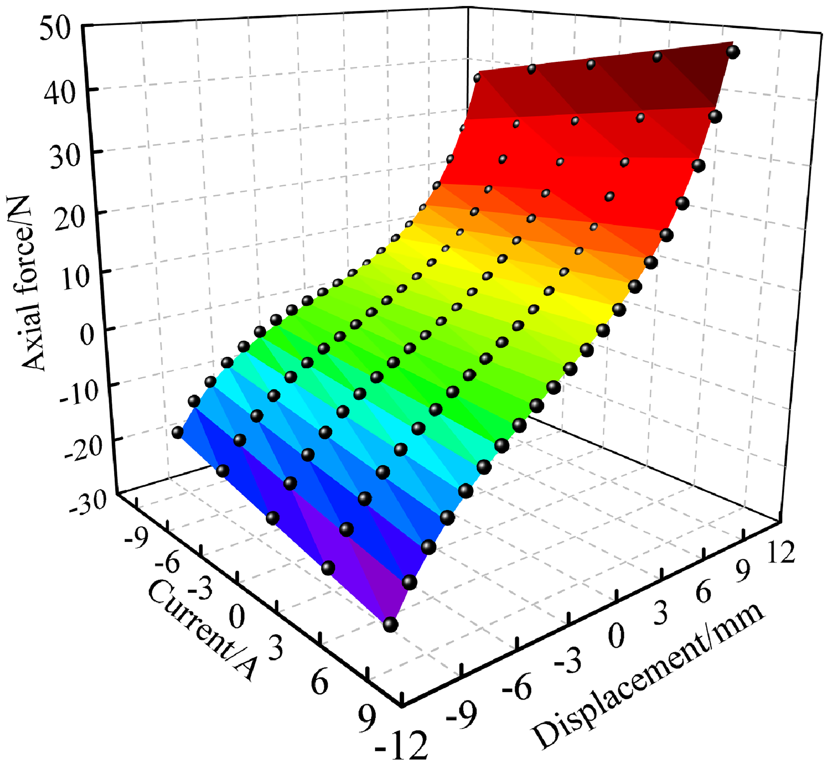
Theoretical calculation and simulation of axial forces.
Structural parameters of vibration isolation system (mm).

Simplify Expression
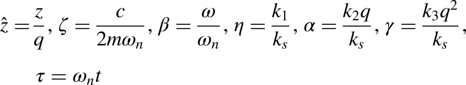
In order to more conveniently solve stiffness and dynamic equations, one common approach is to fit the expression to a cubic polynomial, as shown:
Dynamic Analysis
Dynamic Equations
The dynamic equation of the system under the external displacement excitation zq=qcos(ωt) is:

Vibration Isolation Efficiency Analysis
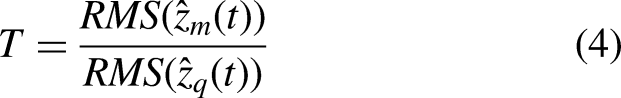
Due to the presence of quadratic and cubic nonlinear terms in the system, the vibration isolation system exhibits pronounced nonlinearity. To further analyze the isolation characteristics of the system, numerical simulations were conducted to compare the displacement transmissibility curves for different excitation amplitudes (q=1mm and q=2mm) for each current. Figure 4(a) illustrates that when q=1mm, the natural frequency of the system and maximum transmissibility decrease as the negative current increases, indicating linear behavior throughout the entire system. Similarly, for q=2mm, the natural frequency and maximum transmissibility also decrease with increasing current, but the transmissibility curve bends to the right, demonstrating typical gradually stiffening spring characteristics.
Simulate the displacement transmissibility under different currents. (a) q=1 mm. (b) q=2 mm.
Experimental Verification
Transmissibility Results
In Figure 1(c), the experimental setup schematic is presented. The Vibration Table Type VT6300-40 is connected to the vibration isolator. The vibration controller of VCS type and the power amplifier of SA3K type regulate the external excitation signal of the shaker. Accelerometers of the 1A23E and 1A113E types are positioned on the vibrating platform and loaded mass, respectively, to detect acceleration signals. The acceleration signals were collected and analyzed using a DH5922N data collector and DHDAS software. Different current signals were applied, and the displacement transmissibility of the designed nonlinear vibration isolator was measured. The vibration isolation mass was 0.4kg, and a sinusoidal excitation signal with a base displacement amplitude of 1mm was loaded for a frequency sweep experiment. Neglecting other influences, assuming a constant damping coefficient.
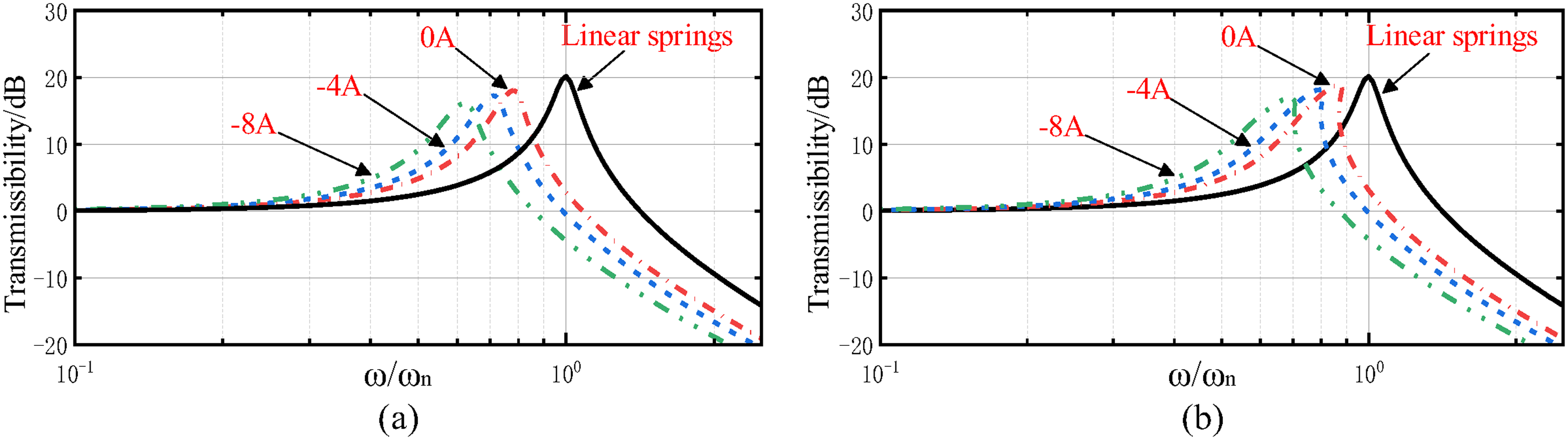
The displacement transmissibility curve obtained from experimental measurements (colored curve) is presented in Figure 5, while the simulated curve is calculated using the IHB (black dotted line). When a −8A current is applied, the natural frequency of the system decreases from 10.62 Hz to 8.64 Hz, the starting isolation frequency decreases from 14.86 Hz to 12 Hz, and the peak of the transmissibility decreases from 18.57 dB to 16.81 dB. The experimental measurements align well with the computational analysis results.
Experimental results of displacement transmissibility under different currents.
Vibration Isolation Performance
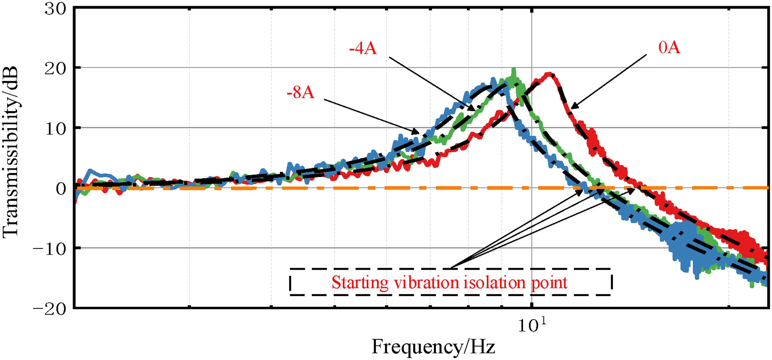
To provide a clearer representation of the vibration isolation efficiency, fixed frequency experiments were conducted at 13.5 Hz, 15 Hz, 20 Hz, and 25 Hz, as depicted in Figure 6(a), (b), (c), and (d). From Figure 6, it can be observed that when a −8A current is applied, the acceleration of the mass block is lower than that of the base, resulting in vibration isolation. The vibration-damping effect is achieved at frequencies of 13.5 Hz (Fig. (a)), 15 Hz (Fig. (b)), 20 Hz (Fig. (c)), and 25 Hz (Fig. (d)). The corresponding attenuation rates are 20.34%, 50.81%, 80.38%, and 90.29% respectively. Moreover, the vibration isolation effect becomes more stable with increasing frequency.
Fixed frequency experiment. (a) 13.5 Hz. (b) 15 Hz. (c) 20 Hz. (d) 25 Hz. Orange, blue, green, and pink represent the acceleration signals measured at the base, 0A, −4A, and −8A respectively.
Conclusion
This paper introduces a new vibration isolation system with high static stiffness and low dynamic stiffness. The method of molecular current is utilized to create a mechanical model for a magnetic spring. Dynamic equations are established, displacement transmissibility is solved, and experiments confirm that the system effectively lowers the intrinsic frequency and expands the vibration isolation range with a negative current. By applying a −8A current, the intrinsic frequency of the system decreases by 18.64%, and the starting vibration isolation frequency decreases by 19.25%. The vibration isolation effectiveness is also tested at various frequencies, showing a reduction of 20.34% at 13.5 Hz and an increased reduction of 90.29% at 25 Hz.
Footnotes
Acknowledgements
This research is supported by National Natural Science Foundation of China (No.52005344). Liaoning Provincial Department of Science and Technology General Program (No.2024-MSLH-372).
Funding
The authors received no financial support for the research, authorship, and/or publication of this article.
Declaration of conflicting interests
The authors declared no potential conflicts of interest with respect to the research, authorship, and/or publication of this article.