
Abstract
Ground-based testing is essential for many aerospace systems due to the high costs and potential risks of flight testing. Currently, a combination of centrifuge and shaking table is generally employed in ground-based testing to create the linear acceleration and vibration environment experienced during spacecraft launches. However, the centrifuge arm, being a typical beam-like structure, fails to accurately reflect the dynamic characteristics of the combined system when regarded as a rigid body. To address this limitation, a rigid-flexible coupling dynamic model of the centrifuge-shaking table system is developed using the finite volume method and multibody dynamics, and dynamic analysis is performed using MBDyn software. The investigation focuses on the effects of rotation speed, tip mass of the centrifuge arm, and excitation force of the shaking table on the system's dynamic characteristics. The results indicate that as the centrifuge rotation speed increases, the displacement of the additional table increases rapidly, while the natural frequency of the shaking table decreases slightly. Furthermore, the tip mass primarily influences the deflection of the arm corresponding to the second mode shape, and the excitation force induces oscillations in the output angular velocity of the centrifuge arm. These simulation results underscore the non-negligible interaction effects within the combined system.
Keywords
Introduction
During launch, spacecraft typically experience linear accelerations and vibrations simultaneously. Traditional testing methods typically focus on evaluating the reliability of equipment sequentially in multiple individual environments. Although this approach was developed over many years and resulted in systems with relatively high reliability, it is complex, time-consuming, and expensive. Research indicates that traditional testing methods fail to capture any potential synergies between the two environment factors.1,2 Currently, the performances of aerospace instruments are tested by attaching a shaking table to the end of the centrifuge arm at centrifuge facilities.3–5 However, due to the inevitable dynamic interaction between the centrifuge and shaking table, unbalanced forces and torques are generated, which greatly affect the output accuracy of the combined system. Therefore, understanding the dynamic coupling between the two is crucial for designing a control system.
However, there is currently limited research on the dynamic interaction of combined system, and past work primarily used structural dynamics and finite element analysis. For example, Cao 6 analyzed the force of the shaking table based on structural dynamics method. The results demonstrated that the force of the shaking table of the combined system far outweigh the ordinary shaking table. Wang et al. 7 built the rigid-flexible coupling model of the combined system by combining ANSYS and ADAMS, and the simulation results indicate that the deformation of the centrifuge arm can significantly influence the precision of acceleration output for the shaking table. In addition, Zhao and Xiang et al.8–11 developed a three-dimensional train-track-bridge system using the finite element method and multibody dynamics, and analyzed the dynamic responses of the system when the train is braking under earthquake. Similarly, the finite element method is utilized in the modeling of beam-like structures.
In this paper, a finite volume beam model is used to model the structural dynamics of a centrifuge arm, with the shaking table system represented as a multi-rigid body model. On this basis, the investigation on the modal characteristics and dynamic interaction effect of the combined system are presented in detail, aiming to provide valuable insight for design of the control system.
Modeling of combined system
Model description for combined system
The structural model of the combined system is established using MBDyn,12,13 a multibody dynamics analysis software developed at the Department of Aerospace Engineering of Politecnico di Milano, Italy. As shown in Figure 1(a), the combined system encompasses a centrifuge base, an arm, two buckets, a counterweight, a shaking table, and an additional table. The centrifuge base is treated as a rigid body using a single static node (i.e., massless) clamped to the ground. The arm is modeled using ten three-node beam elements,
14
totaling 21 structural nodes. The mid-node of the arm rotates around the Z-axis at a specified angular velocity
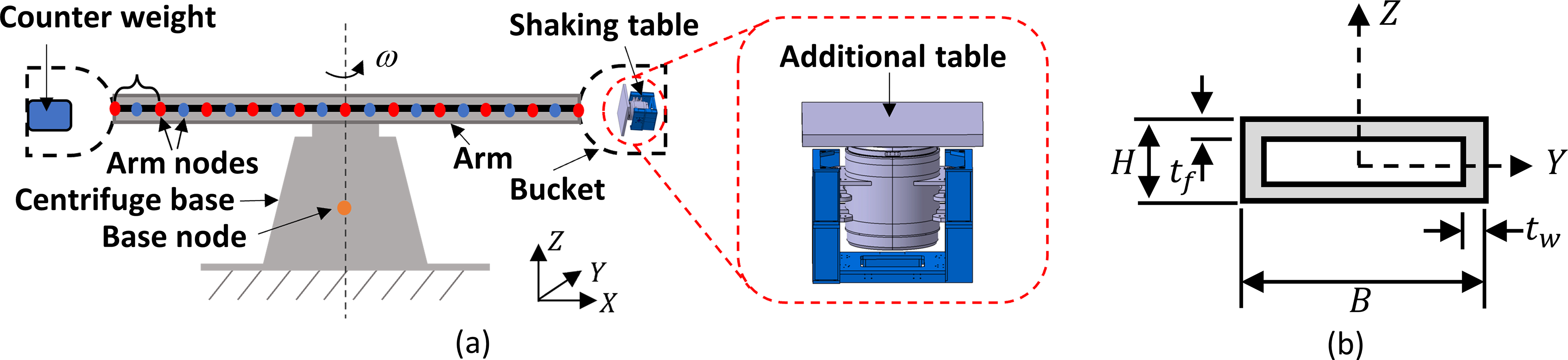
Schematic diagram of the combined system (a) and of the cross-section of the arm (b).
The arm parameters are assigned as follows: (1) the length is L = 5 m, and the dimensions of the cross-section (as shown in Figure 1(b)) are B = 0.59 m, H = 0.13 m, tw = 0.047 m, and tf = 0.05 m, and (2) the elastic modulus, Poisson's ratio and mass density are E = 2.1 × 10¹¹ Pa, μ = 0.3, and ρ = 7850 kg/m3, respectively.
The cross-sectional view of the shaking table is depicted in Figure 2(a). It has a dual magnetic circuit structure and its components are connected by corresponding springs and rigid limit rods. The shaking table is divided into three rigid bodies: a rigid stand, a magnetic steel body (hereafter referred as body), and a moving coil. They are treated as three dynamic nodes. Figure 2(b) shows the flexible connection of the shaking table. The first constraint relationship is among the components of the shaking table. The body and the rigid stand are constrained by a translational joint and four three-dimensional spring-dampers (two on each side), so the body has only one degree of freedom (DOF). Between the moving coil and the body, five three-dimensional spring-dampers are employed. One is positioned at the bottom of the moving coil and the other four are at the top, evenly spaced at 90-degree intervals. Consequently, the moving coil possesses six DOFs. The next constraint relationships are between the shaking table and the other components. The rigid stand is fixed on the right bucket via a fixed joint. The additional table is connected to the moving coil via a fixed joint. Lastly, the specimen is affixed to the additional table by means of a fixed joint. The shaking table vibrates in the X direction and its excitation force is applied to the center of mass of the moving coil.
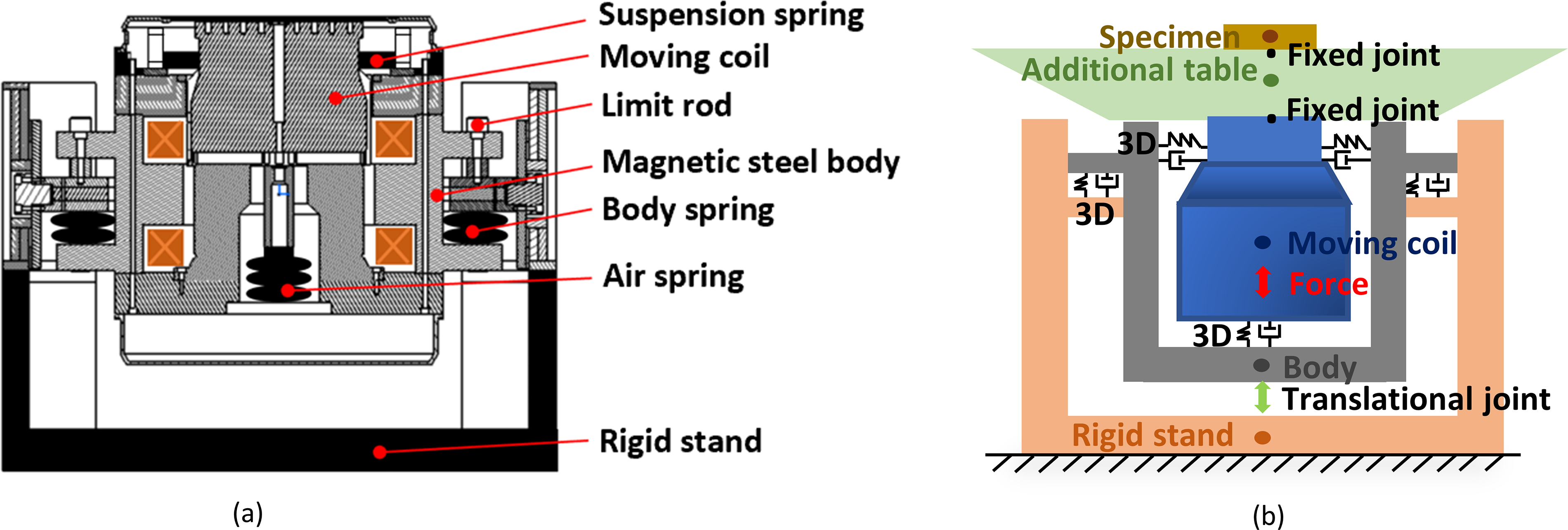
Cross-sectional view (a) and flexible connection (b) of the shaking table.
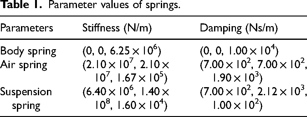
The mass of the rigid stand, the body, the moving coil, the additional table, and the specimen are mr = 80 kg, mb = 300 kg, mc = 120 kg, ma = 100 kg, and ms = 500 kg, respectively. The parameter values of springs are presented in Table 1.
Parameter values of springs.
Mathematical formulation
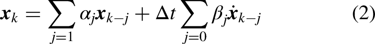
For each constrained system, MBDyn expresses it as a set of implicit first-order Differential-Algebraic Equations (DAE), whose general form is
Rotations are handled in an incremental manner. Owing to the non-vectorial nature of orientation matrices, which belong to the three-dimensional Special Orthogonal group
As mentioned earlier, the centrifuge arm is modeled as a flexible body based on a series of three-node beam elements. As depicted in Figure 3, one beam element is divided into three segments by two evaluation points (squares, Point 1 and 2). These three segments are associated with three reference points (circles), whose motion is associated to that of corresponding structural nodes (stars, Node 1, 2 and 3) by means of rigid offsets. Distributed external forces and moments (
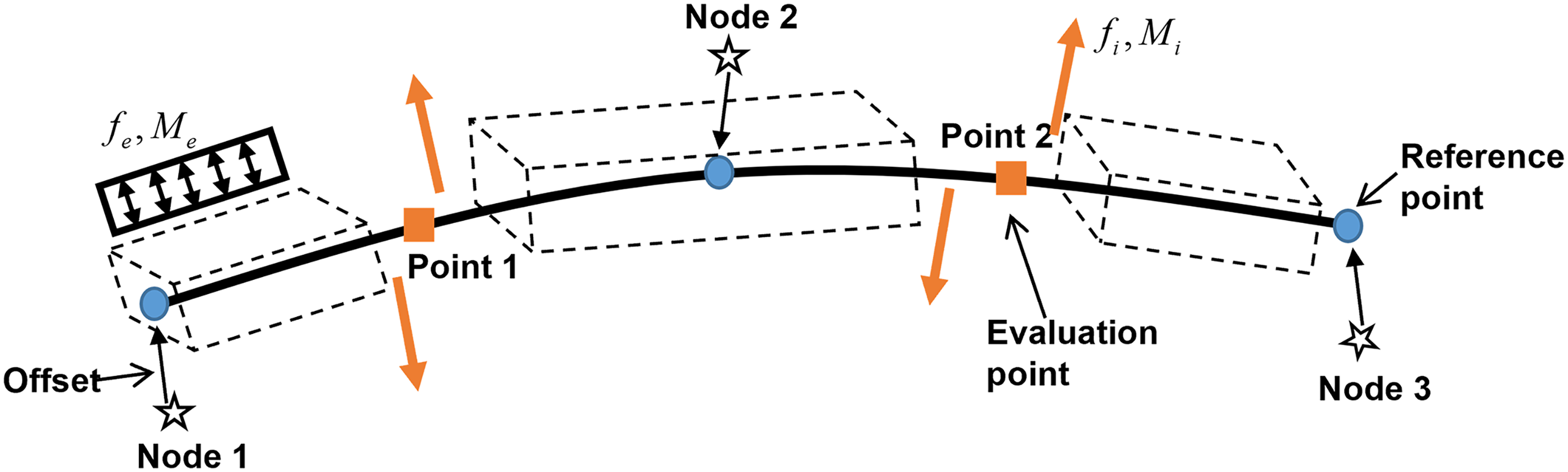
A three-node beam element in MBDyn.
Results and discussion
Due to the vibration direction of the shaking table is parallel to the centrifuge arm, its dynamic response and characteristics are affected by angular velocity. To analyze this factor, the angular velocity is taken to 5, 10, 15, 20, and 25 rad/s, respectively. The displacement of the additional table is plotted in Figure 4(a). It is evident that the displacement increases non-linearly with the rising angular velocity. In addition, when the angular velocity is greater than 11 rad/s, the displacement exceeds the maximum amplitude of the shaking table (10 mm). This situation may cause the moving coil to be unable to vibrate, or even cause damage to the supporting system of the shaking table. Figure 4(b) depicts the amplitude frequency response of the shaking table system under different angular velocities. It is noteworthy that as the angular velocity increases, the amplitude frequency response curve shifts to the left, signifying a decrease in the natural frequency of the shaking table system. This is due to the centrifugal effect resulting from centrifuge rotation affects the inherent properties of the shaking table. However, it is notable that the overall leftward shift of the curve remains within 2 Hz as the angular velocity increases. Consequently, the natural frequency of the shaking table is hardly affected by the change of the angular velocity.
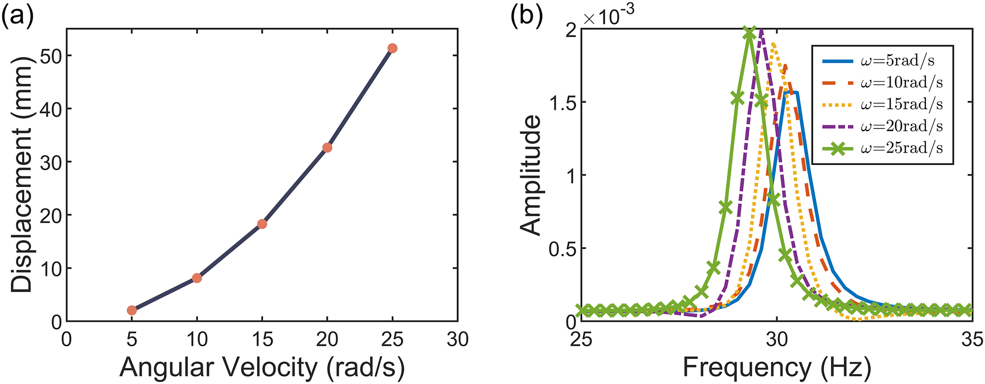
Displacement of the additional table (a) and frequency response of the shaking table (b) under different angular velocities.
On the other hand, the shaking table and the specimen mounted on the tip of the centrifuge arm, their mass and excitation force of the shaking table collectively impact the dynamic response and characteristics of the centrifuge. Defining
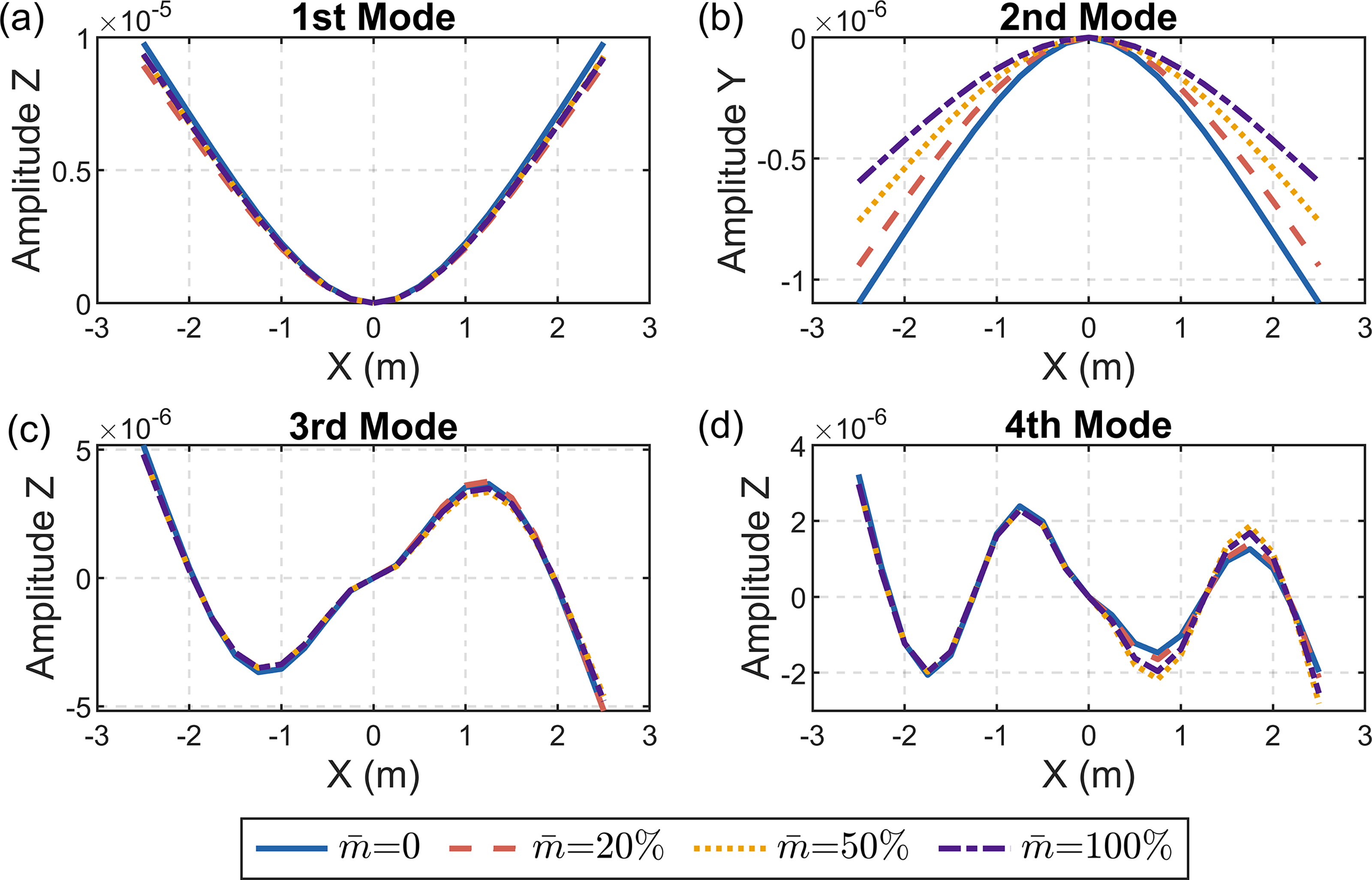
The first fourth mode shapes of the arm for different tip mass.
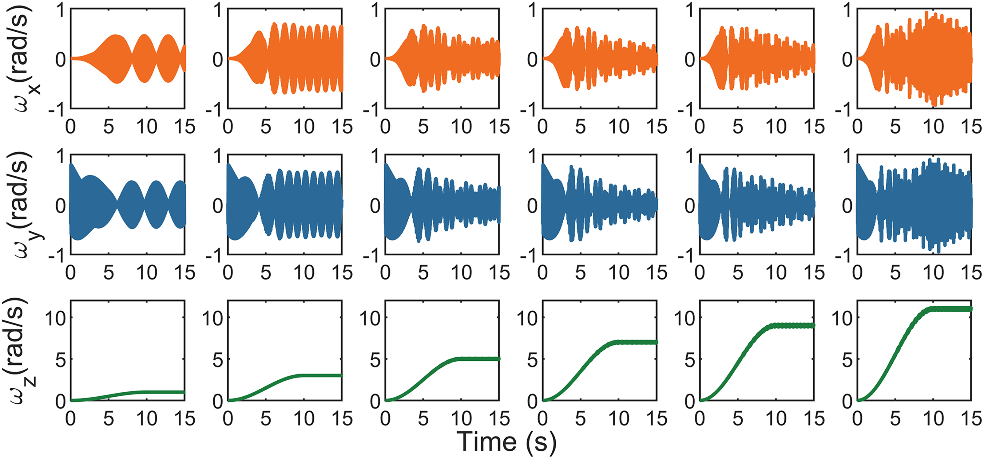
The angular velocity at the end node of the arm.
Conclusions
This paper employs the finite volume method and multibody dynamics to develop a rigid-flexible coupling dynamic model of the centrifuge-shaking table system, considering the flexibility effect of the centrifuge arm. The study revealed that with the increasing rotation speed of the centrifuge, the shaking table displacement exhibits a nonlinear upward trend. When the angular velocity is greater than 11 rad/s, the displacement of the additional table exceeds the maximum amplitude of the shaking table. In addition, the natural frequency of the shaking table is less affected by the rotation speed, except that the natural frequency of the shaking table slightly decreases with the rotation speed increasing. On the other hand, the tip mass significantly affects the deflection of the arm beam's second mode shape, and the excitation force induces oscillations in the centrifuge arm output angular velocity. In conclusion, in the design of a control system, the interaction of the shaking table and the centrifuge are essential considerations that cannot be ignored.
Footnotes
Acknowledgements
The first author (No. 202206280003) has been supported by the China Scholarship Council (CSC) which is gratefully acknowledged.
Funding
The author(s) received no financial support for the research, authorship, and/or publication of this article.
Declaration of conflicting interests
The author(s) declared no potential conflicts of interest with respect to the research, authorship, and/or publication of this article.