
Abstract
Spherical motors represent advanced multi-degree-of-freedom motion devices where precise current calculation is critical for generating target torque outputs. Achieving close-loop control in permanent magnet spherical motors (PM-SpMs) with non-circular symmetric magnetic configuration presents significant technical challenges. This paper proposes an improved particle swarm optimization (IPSO) algorithm enhanced by the full factorial design (FFD) method and applies it to the driving strategy of a PMSpM. First, we implement a bilinear interpolation technique for real-time torque estimation using pre-characterized torque maps, significantly improving computational accuracy and response speed. Following population size determination through conventional trial-and-error analysis, we enhance the classical PSO framework by incorporating adaptive inertia weights and dual adaptive learning factors. Subsequently, the FFD approach systematically optimizes critical IPSO parameters. Comprehensive validation through MATLAB simulations and Minitab statistical analysis demonstrates the efficacy of our FFD- enhanced IPSO algorithm. The experimental results prove the effectiveness and practicability of the proposed driving strategy for the PMSpM.
Introduction
Permanent magnet spherical motors (PMSpMs) offer a potential replacement for conventional multiple degree-of-freedom (DOF) systems that comprise multiple one-DOF electric rotating machineries.1,2 Since PMSpMs have the superiority of multiple DOF motion ability in one compact structure, it has attracted extensive attention in the past decades, and many PMSpM electromagnetic topologies with different control systems have been proposed for massive potential application scenarios.3,4,5
In the context of closed-loop control of a PMSpM, it is essential to construct a torque model tailored to the driving strategy of the PMSpM. Scholars have proposed many torque modeling methods for PMSpMs in the literatures, such as Lorentz force method,6,7,8 virtual work method,9,10,11 and Maxwell stress tensor method. 12 However, all of the aforementioned torque modeling methods are time-consuming and impractical for real-time driving current calculations. Therefore, many driving current calculation methods are proposed by researchers worldwide for the PMSpM real-time driving strategy.
Among these, pseudo-inverse matrix method is frequently used for the PMSpM with circular symmetric magnetic poles. In this method, a special torque-to-displacement curve between one permanent magnet (PM) and one coil is obtained by the analytic torque model 13 or by finite element simulations.14,15 Subsequently, the superposition principle is applied to compute the overall torque of the entire PMSpM. The driving current can be calculated by the total torque via the pseudo-inverse matrix method. This method provides high real-time performance, but it cannot be used for the PMSpM with non-circular symmetric PMs.
Alternatively, data driving methods are black box methods by using the SVM, 16 the Gaussian process, 17 and so on. To avoid the complicated magnetic field modeling in a three-dimensional space, these methods take the PMSpM as a black box, but the training dataset collection is difficult.
Optimization algorithm methods can also be used for the driving current calculations.18,19 We calculate the torque at each point on the spherical surface of the air gap for a coil with a unit current passing through it, and generate the torque map. Subsequently, through the superposition theorem and the swarm intelligence optimization algorithm, we obtain the optimal current values of the actual 24 coils. This method is adopted for the PMSpM with non-circular symmetric magnetic poles, but the real-time performance for the PMSpM driving strategies with tradition intelligent algorithms is unsatisfactory.19,20
This paper conducts research on the driving strategy of the PMSpM with non-circular symmetric PMs, 21 and employs the intelligent algorithm to calculate the driving current of the PMSpM. Firstly, to increase the real-time performance of the PMSpM driving strategy, the bilinear interpolation method is introduced for the torque calculations based on torque maps. Then, an improved particle swarm optimization (IPSO) algorithm is proposed with adaptive dynamic inertia weight and adaptive learning factors. Furthermore, the IPSO algorithm parameter adjustment is implemented by using full factorial design (FFD) experiments. Finally, to verify the effectiveness of the FFD-based IPSO algorithm, simulations and experiments are conducted for the PMSpM driving current calculation.
PMSpM structure and toruqe map
As PMSpMs have a 3D complex structure, it demands a 3D model for analysis. To calculate the driving currents for the PMSpM with non-circular symmetric PMs, the optimization algorithm method, which incorporates torque maps is introduced.
PMSpM basic structure
The PMSpM under study possesses twenty-four electromagnetic cylindrical coils with air cores and these coils are located in two layers, as shown in Figure 1. To enhance the radial magnetic density of the air-gap, sixteen cubic PMs fabricated from NdFeB35 are arranged in a Halbach array along the equator. The rotor sphere, the stator housing, and the pedestal of the PMSpM are all made of aluminum. Thus, the superposition principle is applicable to the PMSpM.
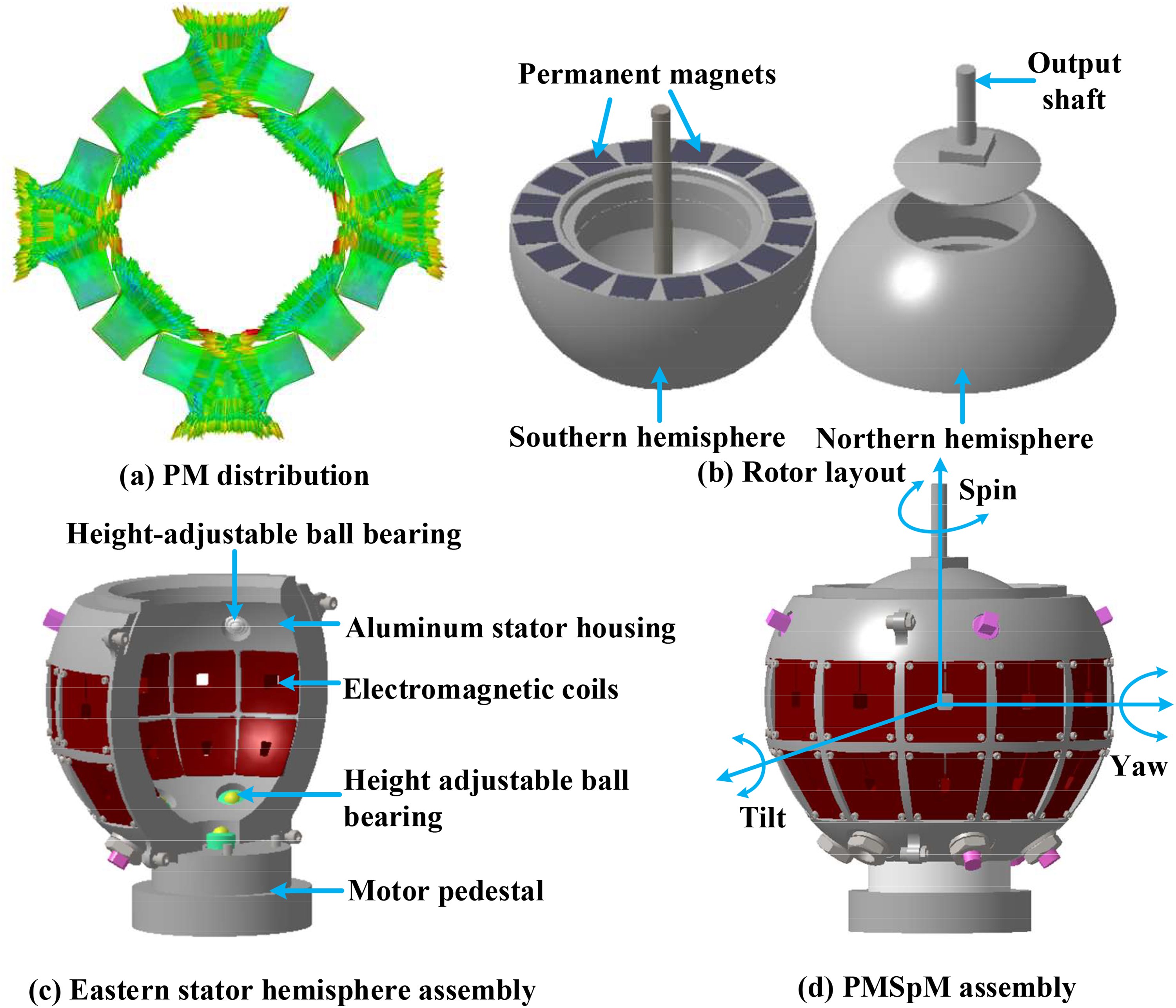
Basic structure of the PMSpM: (a) PM distribution. (b) Rotor layout. (c) Eastern stator hemisphere assembly. (d) PMSpM assembly.
Working principle
The PMs within the rotor sphere are arranged in a Halbach array, as shown in Figure 2. The magnetic density of the air gap is illustrated in an equivalent way. The rotor motion is driven by the interaction force between the PMs and stator coils. The desired trajectory can be achieved by superimposing the three DOF typical motions illustrated in Figure 1(d).
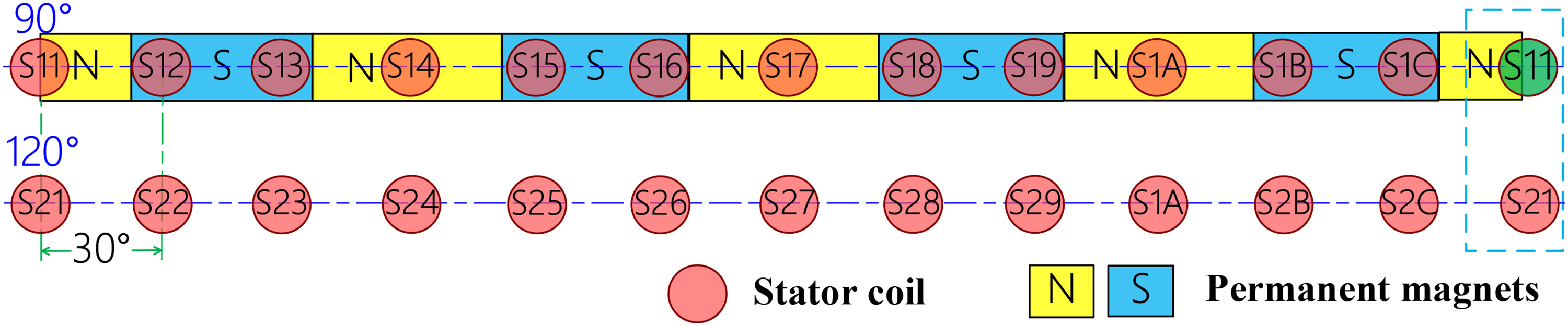
Equivalent schematic of the PMSpM.
Torque map creation
To calculate the torque if know the 24-coil current vector
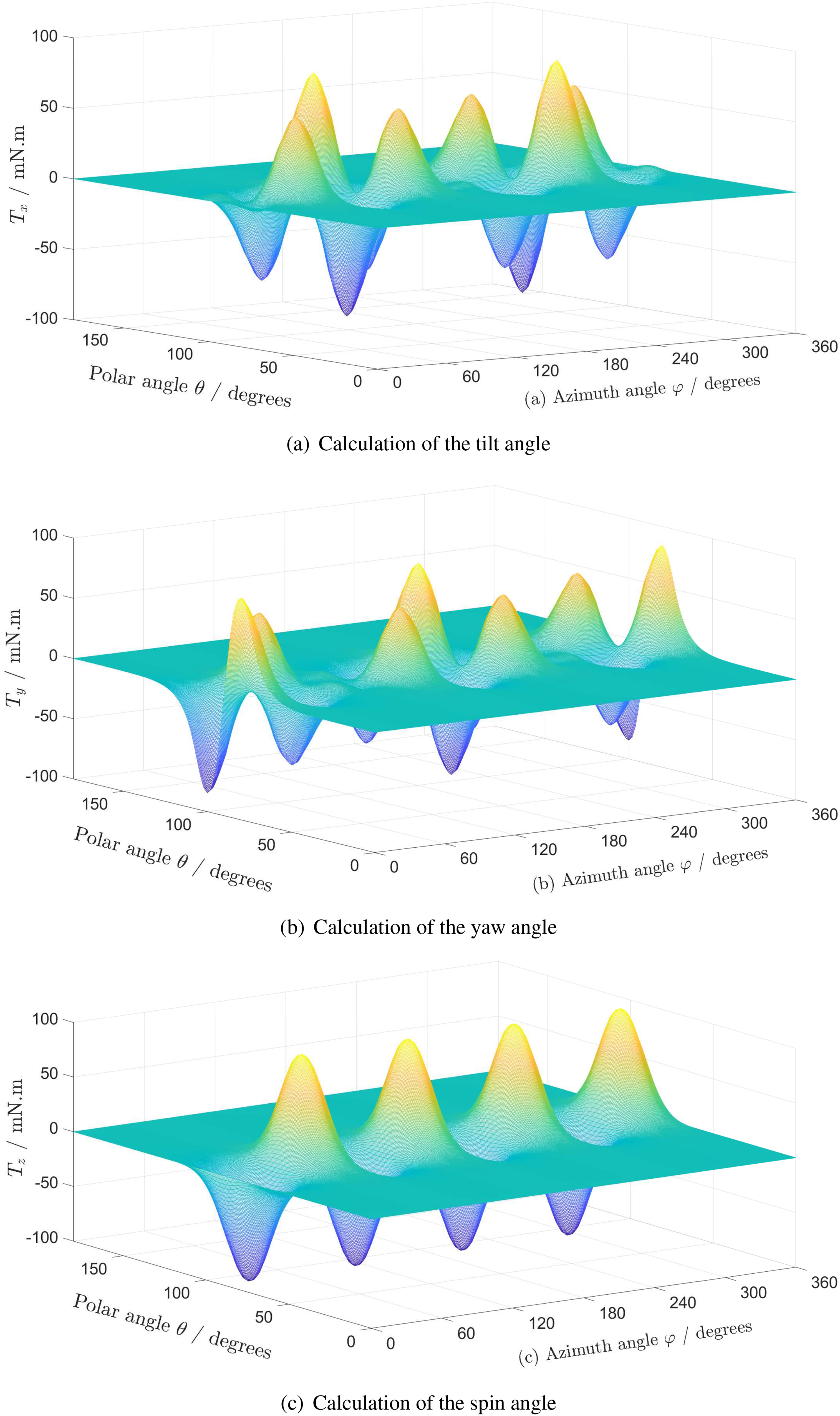
Torque maps of the PMSpM: (a) calculation of the tilt angle. (b) Calculation of the yaw angle. (c) Calculation of the spin angle.
Torque calculation based on torque maps
To calculate the 24-coil current
There are three representative interpolation methods for 2D digital processing, the nearest neighbor interpolation method, the bilinear interpolation method, and the bicubic interpolation method. 22 This paper compares three representative interpolation methods on the torque map Tz. The comparison is shown in Figure 4, where a 1A coil moves along the polar angle θ = 90° and the motion range in the azimuth angle direction is from ϕ = 135° to ϕ = 180°.
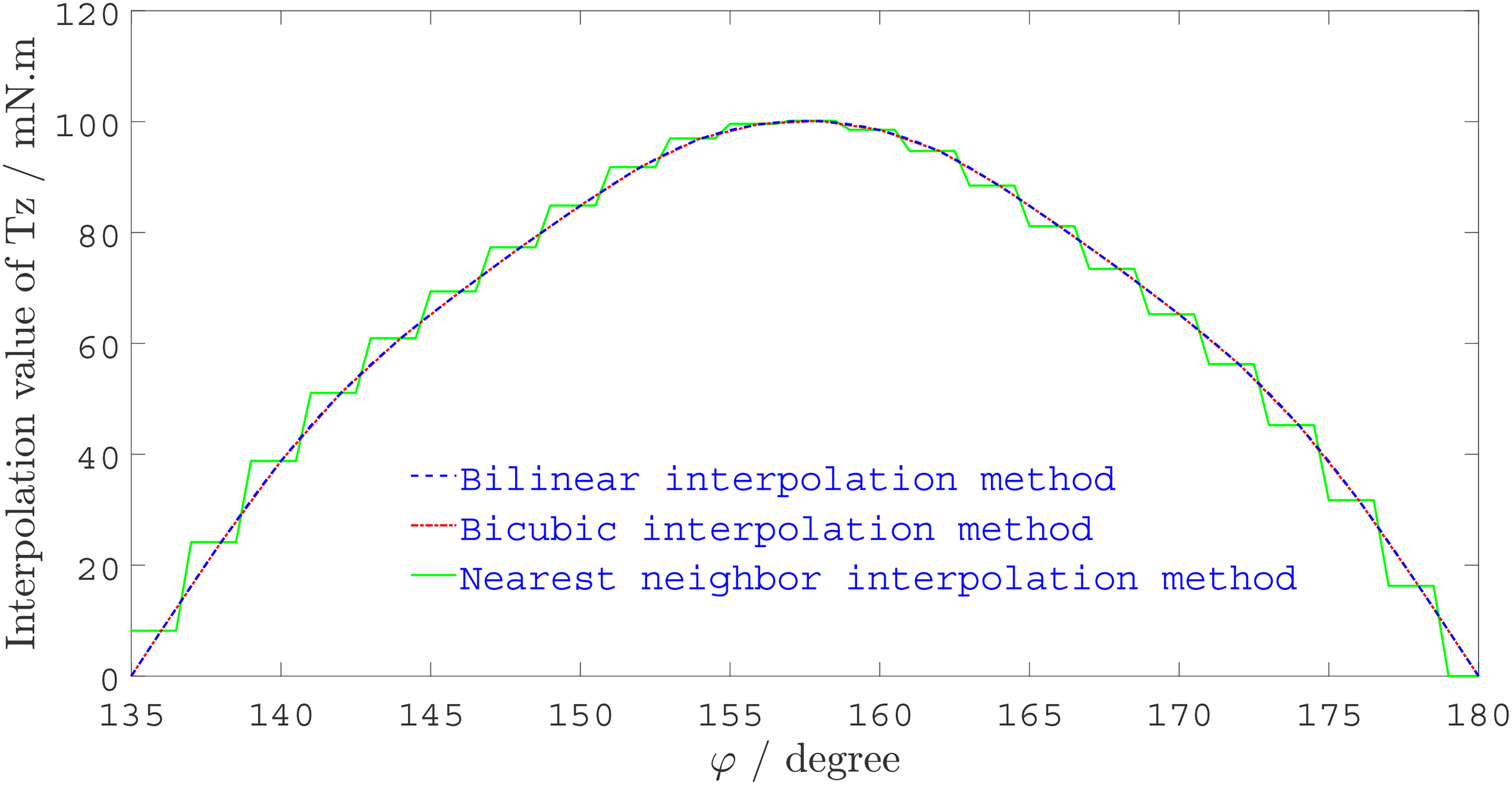
Compare torque maps interpolation.
Considering the torque calculation time together with Figure 4, it is found that the computational time of the nearest neighbor interpolation method in this case is only 4.1 ms with the simplest implementation codes. However, the accuracy of the nearest neighbor interpolation method is not satisfactory, and the result of its interpolation shows a serrated rule. Furthermore, the bicubic interpolation method can provide better accuracy than both the other two methods, but it consumes about 109ms in this case, which is much longer than the other two methods (the consumed time of the bilinear interpolation method is about 5.1 ms). It is worth noting that these calculations are performed on the CAD-LAP as mentioned in the first paragraph of Section 4.1, by means of MATLAB 2021b. To balance the accuracy and the real-time performance, this paper introduces the bilinear interpolation method for torque calculation.
Improvement and implementation of PSO algorithm for PMSpM driving strategy
To increase the real-time performance of the PMSpM driving strategy, this paper proposes the IPSO algorithm based on the classical PSO one and conducts FFD experiments.
Classical PSO algorithm
Early PSO algorithm was proposed according to the foraging behavior of birds in 1995. 23 To increase the search capability, the inertia weight was introduced in 1995. The PSO algorithm with inertia weight is referred to as the standard PSO algorithm and has been widely used in many engineering applications.24,25,26
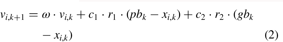
The standard PSO can be expressed as below by updating the positions and velocities of all particle swarms,

Improved PSO algorithm
Adaptive inertial weight improvement
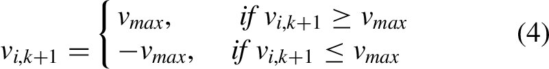
Although the velocity clamping strategy alleviates the swarm explosion issue during the final phase of the PSO iteration, the particles still fail to converge around the most potential solution. Insetad, they oscillate in a wide orbit around the optimal position. Furthermore, adopting concave function will not intensify the algorithm precocity. In contrast, the concave function can improve the convergence performance in the last phase of the PSO iteration. To further mitigate the swarm explosion problem, the effect from the velocity of the previous generation vi,
k
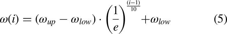
to the current generation velocity vi,
k
+1 needs to be alleviated. Therefore, this paper proposes a concave function of i which is adaptively adjustable by i and applicable to the driving current calculation of the studied PMSpM,
Adaptive learning factors design
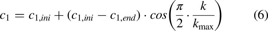
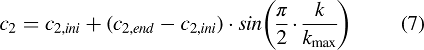
The two learning factors c1 and c2 affect the searching performance via deviate the new position of the particles, and normally they are set as c1 = c2 = 2.05. However, the contribution to search performance of c1 and c2 at the early stage and the late stage is different. If we want to obtain better global exploration performance, the relatively bigger c1 and c2 can explore provided new position is at relatively further area. Contrary to the status above, if we want to enhance the local exploitation performance, more detailed local search needs relatively smaller c1 and c2. In addition, the particle will search towards pbk direction if c1 > c2; otherwise, the particle will search gbk direction if c1 < c2.
27
Therefore, the adaptive learning factors can increase the search performance of the particles in the early stage and the late stage of the algorithm iterations. This paper proposes the adaptive learning factors as follows.
FFD experiments
The parameter combination has a significant impact on the convergence speed of the optimization algorithm. Therefore, to obtain better real-time performance of the PMSpM driving strategy, algorithm IPSO requires parameter tuning. This paper introduces the
FFD experiments to yield suitable algorithm parameters for the IPSO-based PMSpM driving strategy.
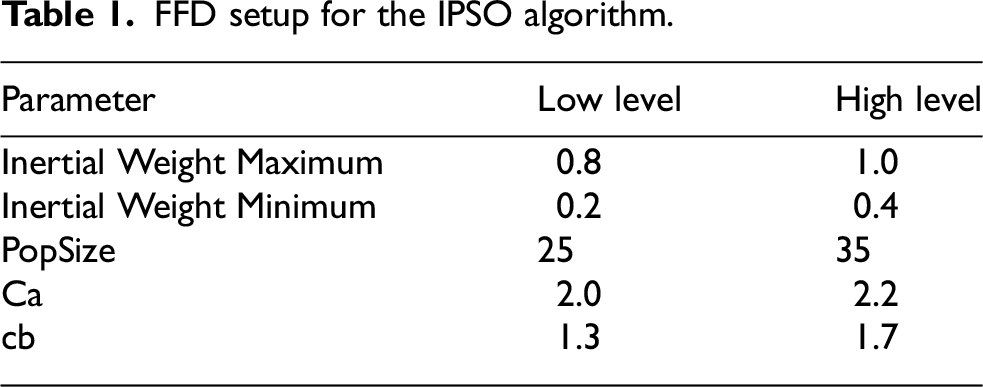
There are five parameters that need to be investigated. This paper designs five-factor FFD experiments with two levels for each factor and three center points. Therefore, the number of FFD experiments is 25 + 3 = 35. The values of the designed FFD experiments can be seen in Table 1. These values are set based on IPSO algorithm simulation verification in Section IV.
FFD setup for the IPSO algorithm.
Driving strategy optimization
This paper studies the IPSO algorithm based PMSpM driving strategy, and the IPSO algorithm implementation process is shown in Figure 5. The PMSpM controller provides the desired torque

IPSO implementation process for driving strategy.
The fitness function of the IPSO algorithm is the function of 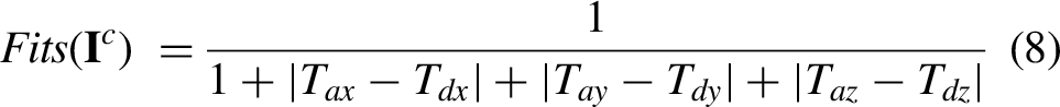
IPSO algorithm simulation verification
To validate the efficacy of the proposed IPSO algorithm, comprehensive simulation experiments are performed for the driving current calculation. Additionally, FFD methodology is systematically implemented to optimize the algorithm's parameter configuration, thereby enhancing its convergence characteristics.
Simulation environment setups for IPSO verification and FFD based parameters adjustment
To verify the effectiveness of the proposed method, this paper compares the IPSO and PSO algorithm under the same simulation criteria. The computer is DELL CAD-LAP (Precision 3541), the CPU of this CAD-LAP is Intel(R) Core (TM) i7-9750H CPU @2.60GHz (12 CPUs) 2.59Ghz, and the RAM is 8.00 G. In terms of the software, the algorithm simulation is conducted by using MATLAB 2021b which is installed in Windows 10.
The FFD based parameters adjustment is carried out by simulation in Minitab (R) 15.1.0.0. We implement the IPSO algorithm in Qt/C++ upper software, as shown in Figure 6. The FFD research is conducted according to the designed FFD experiments in Section III. C, and the data are recorded and analyzed in Minitab.
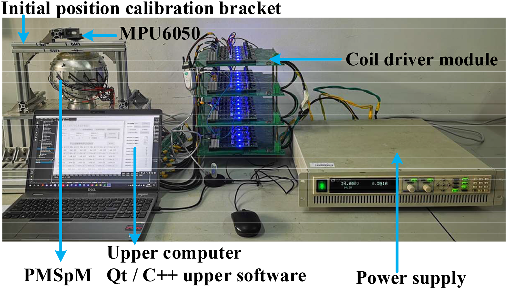
Experimental setup.
The sample size of n = 30 is sufficient to carry out significant statistics according to the central limit theorem.
28
Thus, we execute the PSO and IPSO algorithm in each simulation comparison by 30 times in Sections IV . B and C below, and the simulation tar-get
Systematical simulation of the IPSO-based driving strategy
Population size verification
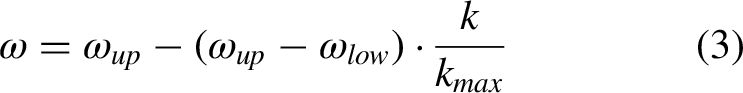
This paper studies the driving strategy of the PMSpM. The population size which is denoted as popsize is not sensitive for the PSO algorithm, and there are also no systematic method for popsize determination. 29 Conventionally, the population size is set as popsize = 20 ∼ 50. To determine the popsize of the PSO algorithm, this paper adopts the typical learning factors (c1 = c2 = 2.05) and the standard inertia weight which is shown as equation (3), where ωup = 0.9, ωlow = 0.4. In addition, the algorithm convergence curves of different population size (popsize = 20, 30, 40, 50) are compared on the fitness function which is shown as equation 8.
Figure 7 shows the different popsize comparison results, where the set of curves in each sub-figures are the 30 algorithm convergence curves in the same working condition, and it is the same for Figures 8, 9, 10. It is concluded that the PSO algorithm can always be converged before generation 250. Bigger popsize will cause more concentrated convergence curves of the PSO algorithm, and the stability of the algorithm is better. However, the convergence speed of the algorithm becomes longer when adopting the bigger popsize. Therefore, to secure the real-time performance of the PMSpM driving strategy, the smaller popsize is more applicable, as proved in Table 2.
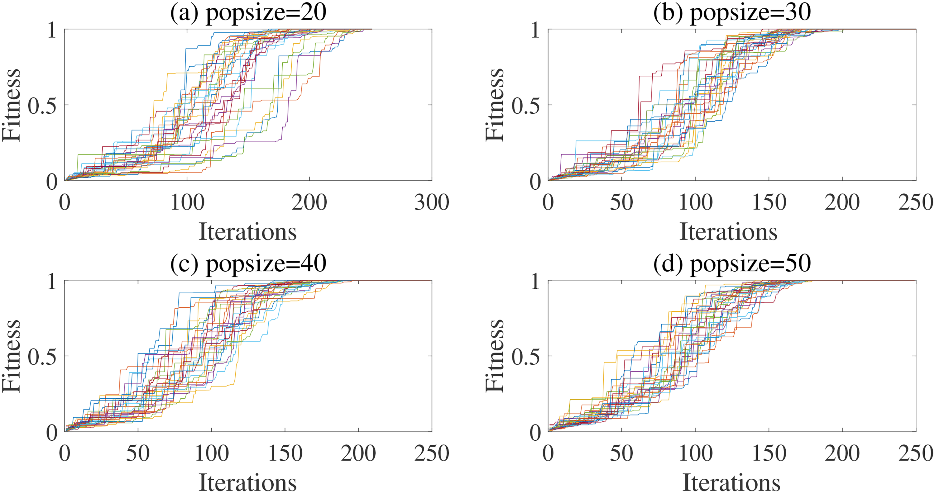
Different popsize comparison for the PSO algorithm: (a) popsize = 20. (b) popsize = 30. (c) popsize = 40. (d) popsize = 50.
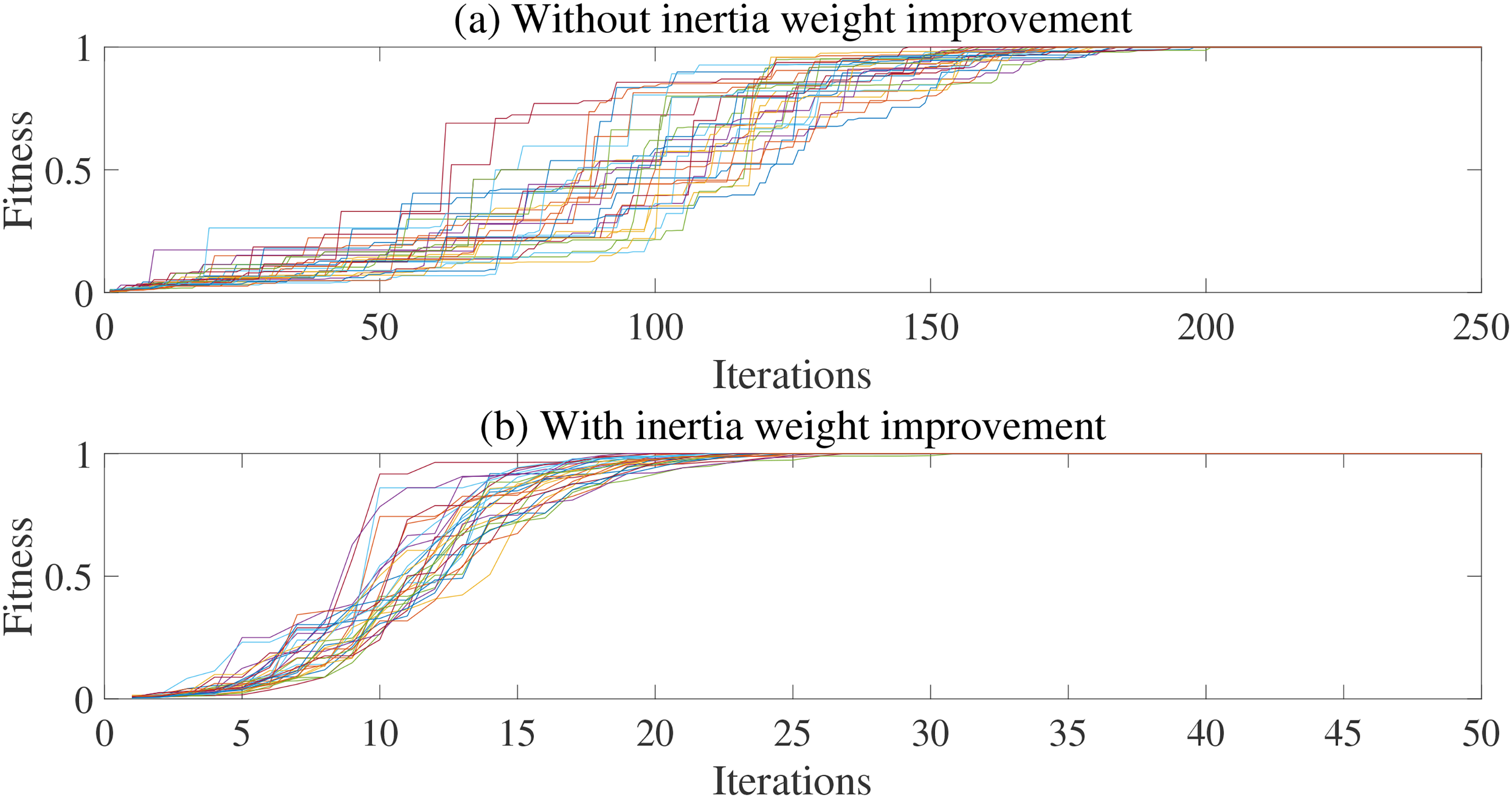
Comparison of inertia weight in simulation: (a) without inertia weight improvement . (b) With inertia weight improvement.
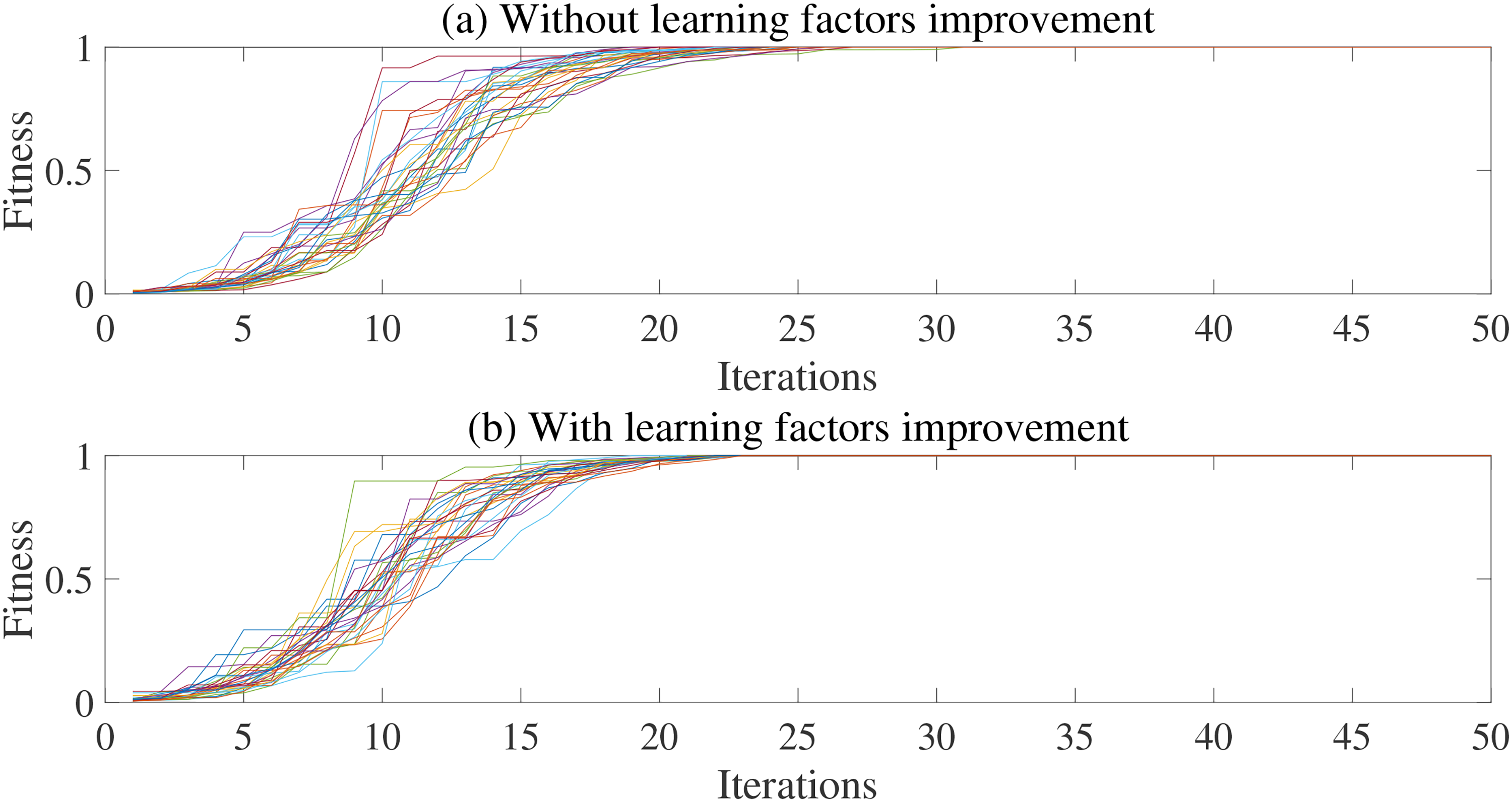
Comparison of learning factor improvement: (a) without learning factors improvement. (b) With learning factors improvement.
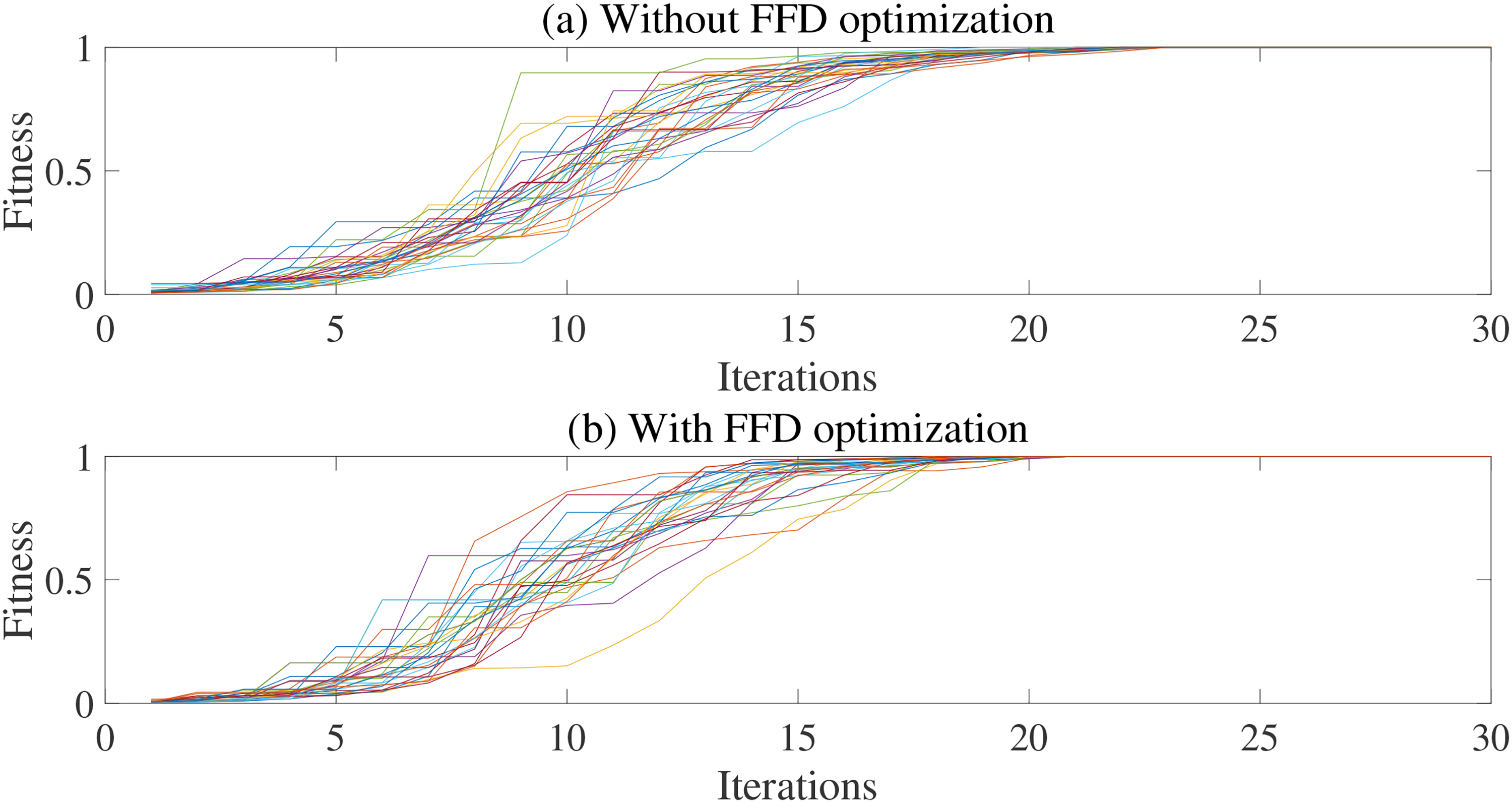
Comparison of FFD based parameter adjustment: (a) without FFD optimization. (b) With FFD optimization.
PSO performance comparison for different popsize.
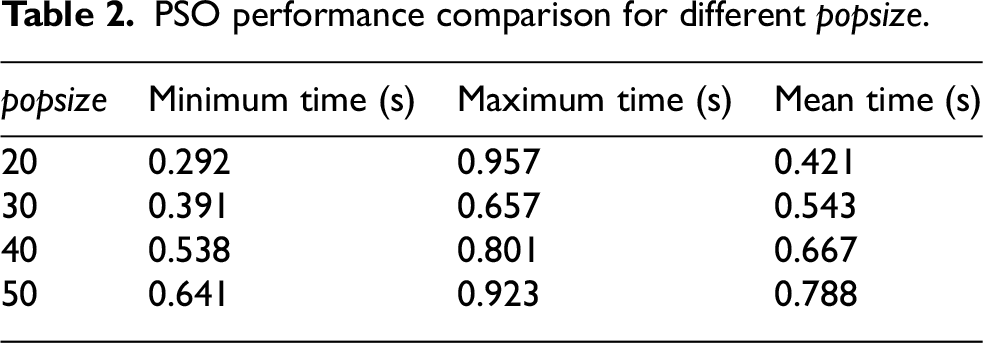
It is worth noting that the convergence rate of the bottom right curves in Figure 7(a) are obviously higher than other curves. Thus, too small a popsize may cause the risk of falling into local optimality. Since the PMSpM driving strategy focuses more on real-time requirements, to balance the accuracy, the algorithm robustness, and the convergence rate of the algorithm, this paper adopts popsize = 30.
Adaptive inertia weight verification
Figure 8 shows a comparison between the PSO algorithm with a standard inertia weight and the same algorithm with an improved adaptive inertia weight. In this case, ωup = 0.9 and ωlow = 0.4. It is found that the convergence generation of the algorithm is reduced from about 200 to 30.
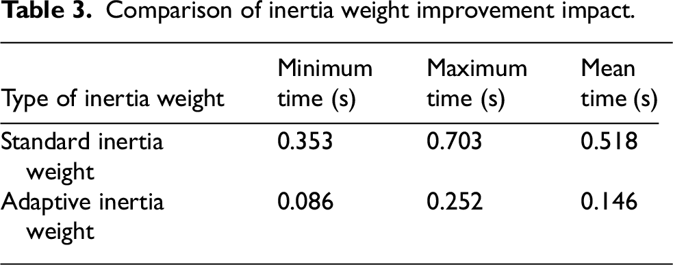
Table 3 shows that the mean convergence time of the PSO algorithm with improved inertia weight is only 22.3% of the counterpart of the standard PSO algorithm. The mean convergence rate is reduced from more than 518ms (the maximum time is 858ms) to only about 146 ms. In addition, the robustness of the algorithm is enhanced since the convergence curve bundle is more concentrated in Figure 8(b). Therefore, equation (5) is an effective improvement of the inertia weight for the standard PSO algorithm for the PMSpM driving strategy.
Comparison of inertia weight improvement impact.
Adaptive learning factors verification
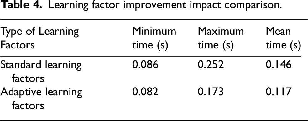
With the exception of the inertia weight improvement, proper learning factors can also enhance the convergence performance of the PSO algorithm. Figures 9(a) and (b) show the comparison results for the learning factors improvement. It is concluded that improving the learning factors based on inertia weight optimization is capable of cutting time for the PSO algorithm convergence, and the convergence generation of the algorithm can be reduced from about generation 30 to 25. Table 4 shows the comparison of the learning factors improvement impact. It is found that the mean running time of the algorithm with standard learning factors and improved inertia factors is 146ms, and the convergence time of the algorithm with improved adaptive learning factors (noted as IPSO algorithm) is 117ms. Thus, the real-time performance of the IPSO algorithm is improved by 20%.
Learning factor improvement impact comparison.
FFD based IPSO parameters
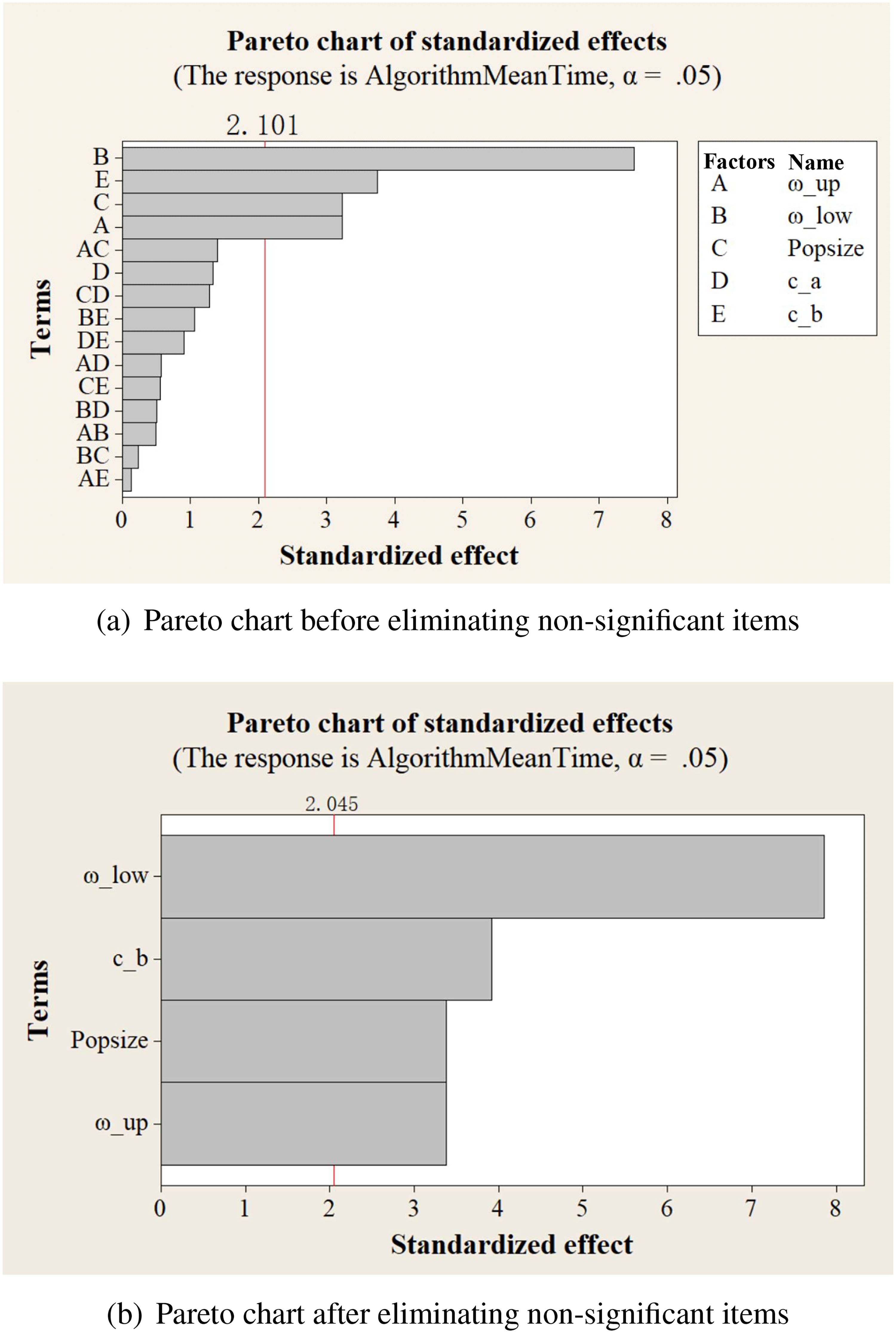
To enhance the convergence performance of the IPSO algorithm, this paper employs FFD experiments for the systematic parameter optimization. Since the interaction of factors with three and more orders is normally not significant, 28 we only evaluate the significance for all the factors and their interaction of second order, and the Pareto chart in Figure 11(a) illustrates the absolute values of the effects. It is found that ωup, ωlow, popsize, and Cb are all significant with p-values less than α of 0.05. After removing non-significant items and re-analyzing, the updated Pareto chart with all significant terms is shown in Figure 11(b), and the regression equation is optimized in Minitab statistic software.
Comparison of Pareto chart: (a) Pareto chart before eliminating non-significant items. (b) Pareto chart after eliminating non-significant items.
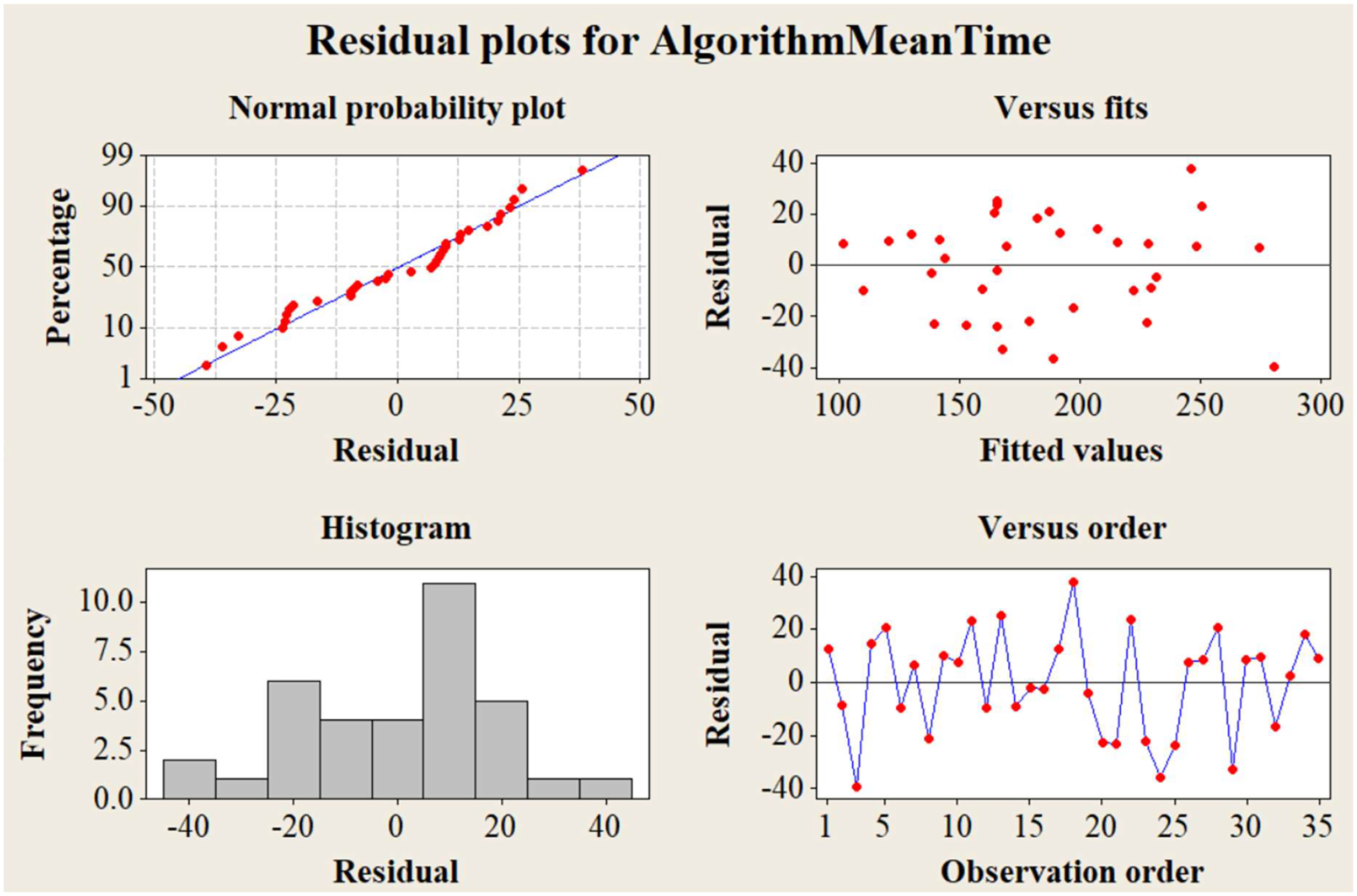
Figure 12 demonstrates the four-in-one residual plots of the optimized regression model. The normal probability plot and the histogram plot indicate that the residuals are normally distributed. Moreover, the versus fits plot shows that the residuals are scattered randomly around zero, and there is no obvious pattern in the versus order plot. Therefore, the optimized regression model in Minitab is applicable.
Four-in-one residual plots.
To obtain suitable parameters of the IPSO algorithm for the PMSpM driving strategy, this paper introduces the response optimizer in Minitab statistical software, where the response variable AlgorithmMeanTime for the optimization is the mean convergence time of the IPSO algorithm. After setting the small optimization goals, the Minitab simulation can yield the optimized parameters of the IPSO algorithm as follows: ωup = 1.0, ωlow = 0.4, popsize = 35, and cb = 1.7. Note that the non-significant factor ca = c1,end = c2, ini is still set as 2.05, and the predicted convergence rate of the IPSO based PMSpM driving current strategy is about 101.8 ms.
Figure 10 illustrates the comparison results between the IPSO algorithm with and without FFD based parameter adjustment. It is concluded that the bundle of convergent curves for the IPSO algorithm with FFD based parameter adjustment is concentrated earlier (at about generation 20) than the IPSO algorithm without parameter adjustment (at about generation 25). Moreover, the AlgorithmMeanTime for the IPSO algorithm with FFD based parameter adjustment is 103ms, and the deviation from the Minitab response optimizer prediction value (101.8 ms) is 1.16%. Therefore, the FFD based parameter adjustment is effective and significant for increasing the real-time performance of the IPSO algorithm for PMSpM driving strategy.
Experimental verification of the IPSO-based PMSpM driving strategy
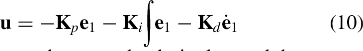
To validate the feasibility of applying Algorithm IPSO in Scenario PMSpM driving strategy, this paper devises a straightforward control experiment using the PID controller.
PMSpM control system design
According to theoretical mechanics, the PMSpM dynamic model can be expressed as
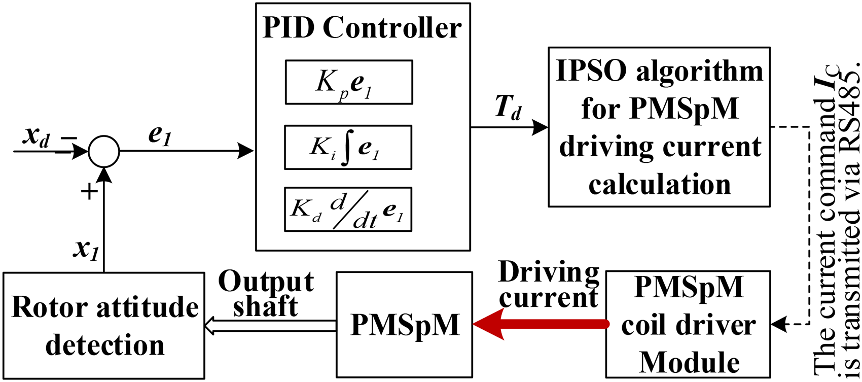
PMSpM control system structure.
Experimental setup
This paper designs a simple control experiment to verify the feasibility of the IPSO algorithm with FFD based parameter adjustment. The testing bench is composed of one PMSpM prototype, one coil driver, one upper computer with Qt/C++ upper software, one MPU6050 sensor, one power supply and one initial position calibration bracket, as shown in Figure 6.
The MPU6050 is used to detect the attitude of the PMSpM rotor sphere. The upper software gets the rotor attitude from MPU6050 via Bluetooth. The PMSpM driving current order
Experimental verification of PMSpM control
This paper designed a simple tilt motion control experiment. Figure 14 shows trajectory control results which denote that the rotor moves from Point A to Point B. It is concluded that the rotor motion trajectory
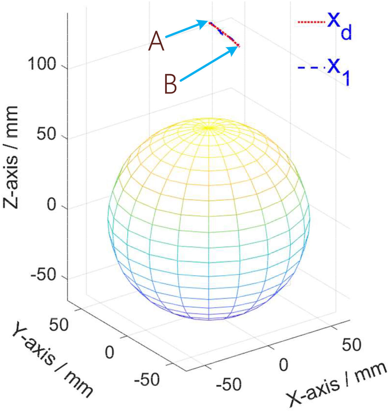
Motion trajectory of the PMSpM control.
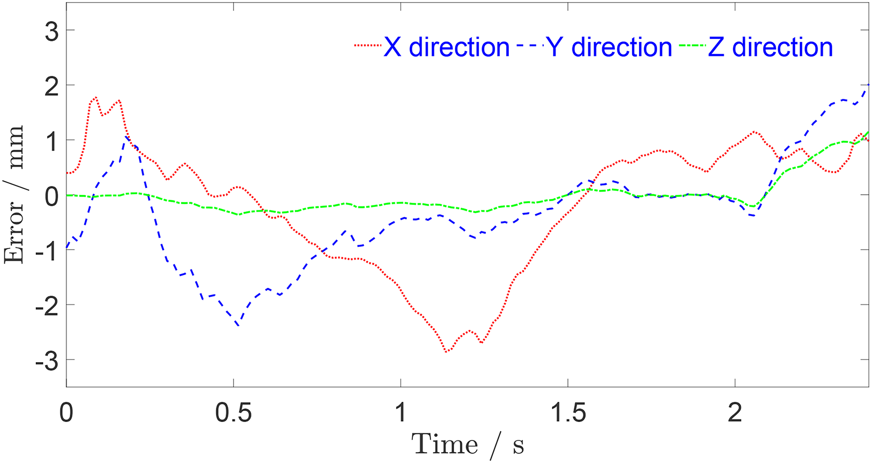
Motion error of the PMSpM control.
It should be noted that, since the convergence time of the IPSO algorithm requires about 100ms for the PMSpM driving current calculation, the real-time performance of the proposed method is still a great challenge to the application of the reverse-torque model from the desired torque to the current. Currently, the system is unable to support rapid motions and motions with a large spatial gap between two adjacent control points. Future research will focus on enhancing the computing power of the system control platform and improving the real-time performance of swarm intelligence optimization algorithms, thus further promoting the control studies of PMSpM based on the torque map.
Conclusion
This paper proposes an IPSO algorithm for the PMSpM driving strategy, and tunes its parameters using FFD method. Firstly, the torque maps are generated for the PMSpM. Subsequently, a bilinear interpolation technique is employed in the current-to-torque cal-culation to achieve optimal equilibrium between computational precision and real-time performance requirements. Then, the PSO algorithm is used for the PMSpM driving strategy. On the basis of the PSO algorithm, the adaptive inertia weight and the adaptive learning factors are adopted, and the IPSO algorithm is introduced. To get better realtime performance of the PMSpM driving strategy, the FFD experiments are employed for the parameter adjustment of the IPSO algorithm. Finally, the simulation and experiment results show that the proposed IPSO algorithm with parameter adjustment method is effective and applicable to the PMSpM driving strategy.
The proposed PMSpM driving strategy using IPSO algorithm with FFD parameter adjustment method enables closed-loop control for this type of PMSpM with non-circular symmetric PMs, and the real-time performance and the robustness of the PM-SpM driving strategy can be enhanced. However, to ensure stable convergence of the IPSO algorithm, the variation range for each particle is relatively large. This results in an oversized IPSO-optimized control current command
The IPSO-based driving strategy via FFD parameter adjustment is applicable to driving current calculations of other complex special motors.
Footnotes
Acknowledgment
This work was supported in part by Scientific Research Initiation Foundation for Introducing Talents of Anhui University of Science and Technology under Grant 2022yjrc45, in part by Natural Science Research Project of Anhui Educational Committee under Grant 2022AH050835, in part by the Regional Innovation Joint key Project of China's National Natural Science Foundation under Grant U23A20647, and in part by the China National Natural Science Foundation under Grant 52174141.
Funding
The authors received no financial support for the research, authorship, and/or publication of this article.
Declaration of conflicting interests
The authors declared no potential conflicts of interest with respect to the research, authorship, and/or publication of this article.