
Abstract
This study focuses on optimizing a high-speed multiphase electrical machine intended for aerospace power generation (2.25 MW/15,000 rpm). The proposed approach relies on analytical modeling to capture both electromagnetic and thermal phenomena. A direct stator winding cooling strategy, based on oil circulation within the slots and end-windings, is investigated. The objective is to minimize the mass of the active components while satisfying specific design constraints. To ensure fault tolerance, the influence of the number of phases and the winding distribution on machine performance is analyzed. Particular attention is devoted to the machine's ability to withstand short-circuit currents.
Introduction
Industrial standards require continuous advancements in the reliability and performance of electrical machines. This is especially crucial for systems operating in critical environments, such as aerospace, where minimizing mass, maximizing efficiency, and ensuring fault tolerance are key priorities. This system-level integration is notably illustrated in recent works on the SMR-CON (Small and Medium Range Conservative) aircraft from the European project IMOTHEP, 1 which employs a turbo-electric Distributed Electric Propulsion (DEP) architecture. In this configuration, the power generation stage is critical: it relies on turboshafts mechanically coupled to high-power generators to feed a distributed cluster of electric fans. Consequently, these generators are constrained to operate at high rotational speeds (e.g., 8200 RPM) to match the optimal operating point of the power turbine. To address safety requirements, the architecture implements a cross-redundant DC distribution where generators feed split buses, ensuring that the failure of one turboshaft or generator does not result in a critical loss of thrust or parasitic yawing moments. Additionally, to offset the weight penalty of the electrical chain, these machines target very high performance figures, such as an active specific power of 19.3 kW/kg and an efficiency of 99%. These targets align with recent reviews on regional aircraft electrification, which emphasize the need for MW-class machines capable of meeting stringent specific power targets. 2 However, as highlighted in, 3 achieving these high densities must not compromise safety, making fault-tolerant designs mandatory for propulsion applications. Furthermore, pushing these limits requires a system-level perspective to balance the conflicting electromagnetic, thermal, and mechanical constraints. 4
Surface mounted Permanent Magnet Synchronous Machines (PMSMs) are promising candidates for these applications.5,6 However, designing such machines is challenging, as it requires considering multiple factors such as geometry, material selection, cooling strategies, and fault tolerance to achieve an optimized configuration. While magneto-thermal optimization strategies aiming at mass minimization are well-established in the literature, they often treat fault tolerance as a secondary check rather than a primary design driver. In particular, ensuring resilience against short-circuit faults dictates specific inductance values to limit the fault current, which often conflicts with the objective of maximizing power density. Consequently, integrating accurate inductance calculation directly into a high-speed sizing loop remains a gap in current analytical approaches.
The main contribution of this work lies in a holistic analytical framework that bridges this gap. It incorporates the computation of inductances within the multi-physics optimization loop, allowing for the simultaneous satisfaction of thermal limits and short-circuit constraints. This enables the rapid exploration of the design space for multi-star architectures, allowing for a precise trade-off analysis between power density and fault tolerance that would be computationally prohibitive using Finite Element Analysis (FEA) alone.
This article presents an optimal analytical design approach for a PMSM, integrating a direct winding cooling system based on oil circulation.6,7 The methodology relies on holistic framework where a lumped parameter thermal model is fully coupled with the electromagnetic sizing. A key specificity of this approach is the explicit integration of inductance calculation within the optimization loop, ensuring intrinsic short-circuit fault tolerance by design. The objective is to minimize the active mass while satisfying stringent constraints on efficiency, power factor, rotor mechanical integrity, and winding temperature. Finally, the study highlights the critical trade-offs between power density, supply compatibility (power factor), and short-circuit current capability.
Analytical models for design
Electromagnetic Model
The electromagnetic model is based on the classical expression of electromagnetic torque:

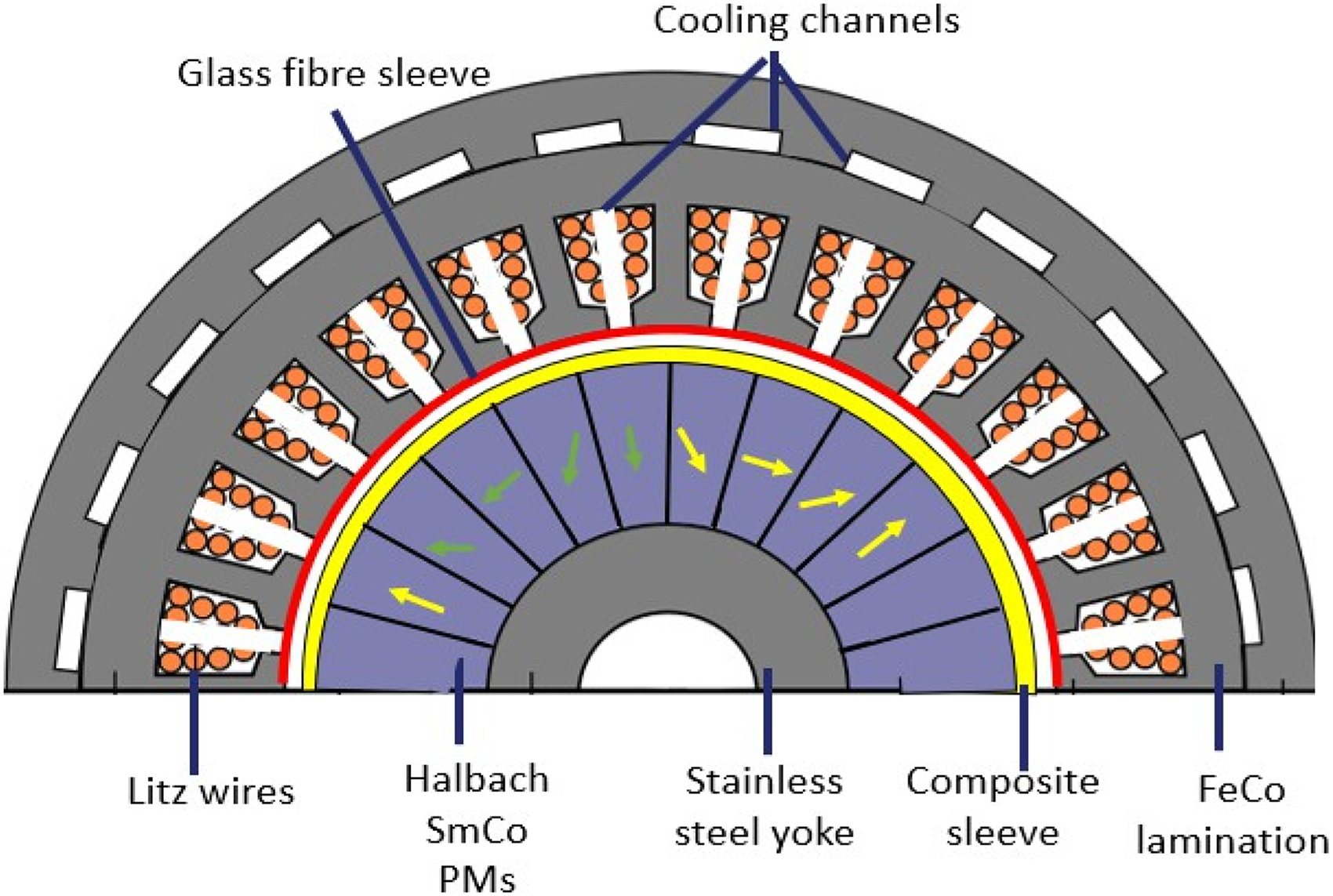
Structure of the PMSM with the cooling system for windings and stator yoke.
Thermal Model
The thermal model is based on the machine geometry of Figure 1, which also depicts the cooling ducts. It incorporates key thermal properties of the cooling fluid, including density, viscosity, thermal conductivity, as well as the inlet temperature and flow rates. Using these input parameters and the thermal losses derived from the electromagnetic calculation (Joule and iron losses), the model estimates the temperatures of both slots and end-windings.
Effective thermal management is identified as the primary bottleneck for increasing power density in recent aerospace reviews.9,10 Consequently, conventional cooling methods are replaced in this study by a high-flow direct oil cooling system, an architecture successfully implemented in high-performance generators5,6 to maximize mass power density.
Following the modeling methodologies validated in7,11 oil is injected at the end-windings and flows through rectangular channels located in the middle of the slots and along the outer surface of the stator, as depicted in Figure 1. At the bore radius, a glass-fiber layer is used as thermal insulation. It prevents the cooling oil from flowing down and also limits heat transfer toward the rotor.
A seven-node thermal network is established for the analysis. Only the stator is considered, since the heat transfer from the stator to the rotor is negligible. As shown in Figure 2, the machine is divided into four conductive blocks: yoke, tooth, slot, and end-windings. Owing to symmetry, only half a tooth pitch over half the machine length is modeled. Each conductive block is represented by an equivalent thermal circuit, derived from a basic unidirectional model.
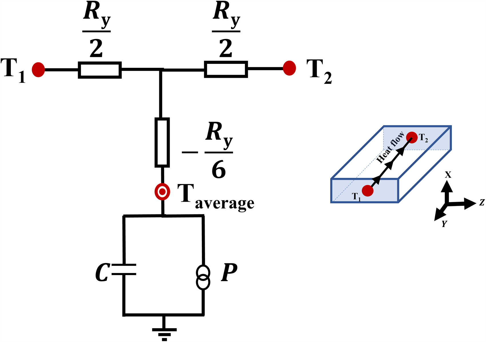
Unidirectional thermal model along the radial direction (y).
The thermal losses calculated from the electromagnetic model are applied at the average temperature node,
Each block is represented by an equivalent thermal circuit (1D, 2D, or 3D), which is derived from the fundamental one-dimensional model illustrated in Figure 3. 11
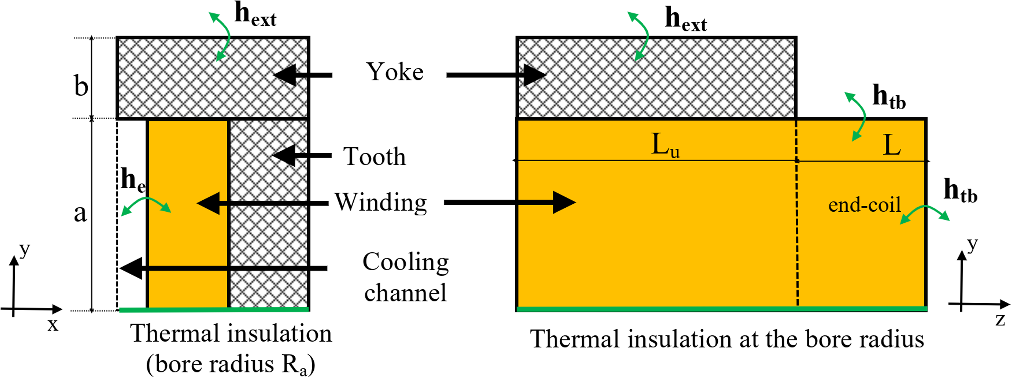
Representation of a half-tooth pitch for thermal modeling.
Thermal models of each block
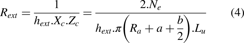
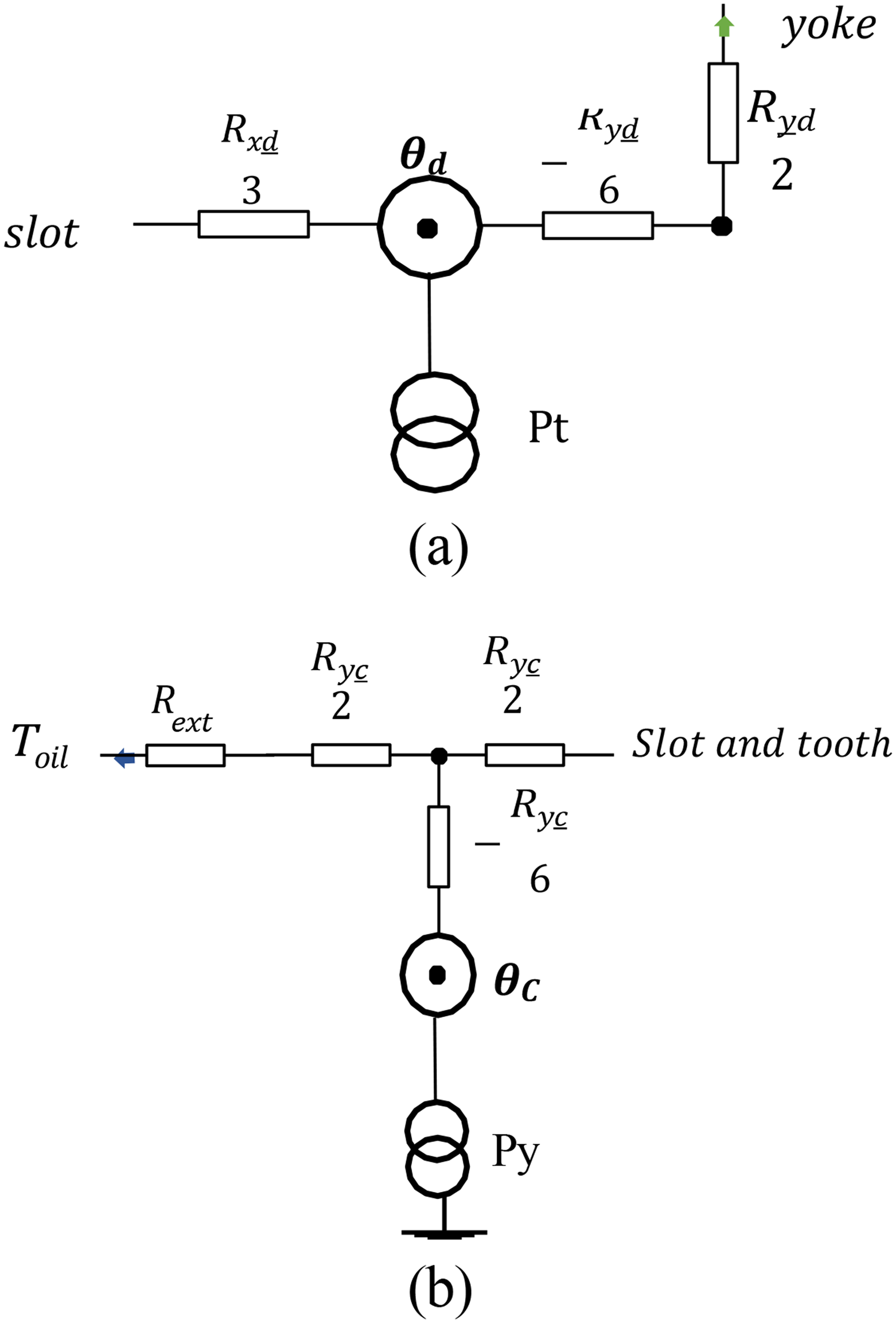
Figure 4 presents the equivalent thermal model for a tooth (a) and for the yoke (b). In these diagrams, θd and θ denote the average temperature of a tooth and of the yoke, respectively. The terms Pt and Py represent the iron losses of each element derived from the electromagnetic model (see subsequent expressions). The thermal resistance expressions for the yoke, expressed at the mean radius, are given below, where Kyc denotes the thermal conductivity of the yoke. Similarly, Figure 5 presents the thermal model of a slot with winding, and Figure 6 depicts the equivalent thermal circuit for the end-coil, both accounting for heat transfer along the X, Y, and Z axes.
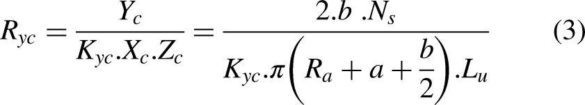
Thermal model for: (a) a tooth (heat transfer along X and Y); (b) the yoke (purely radial heat transfer along Y).
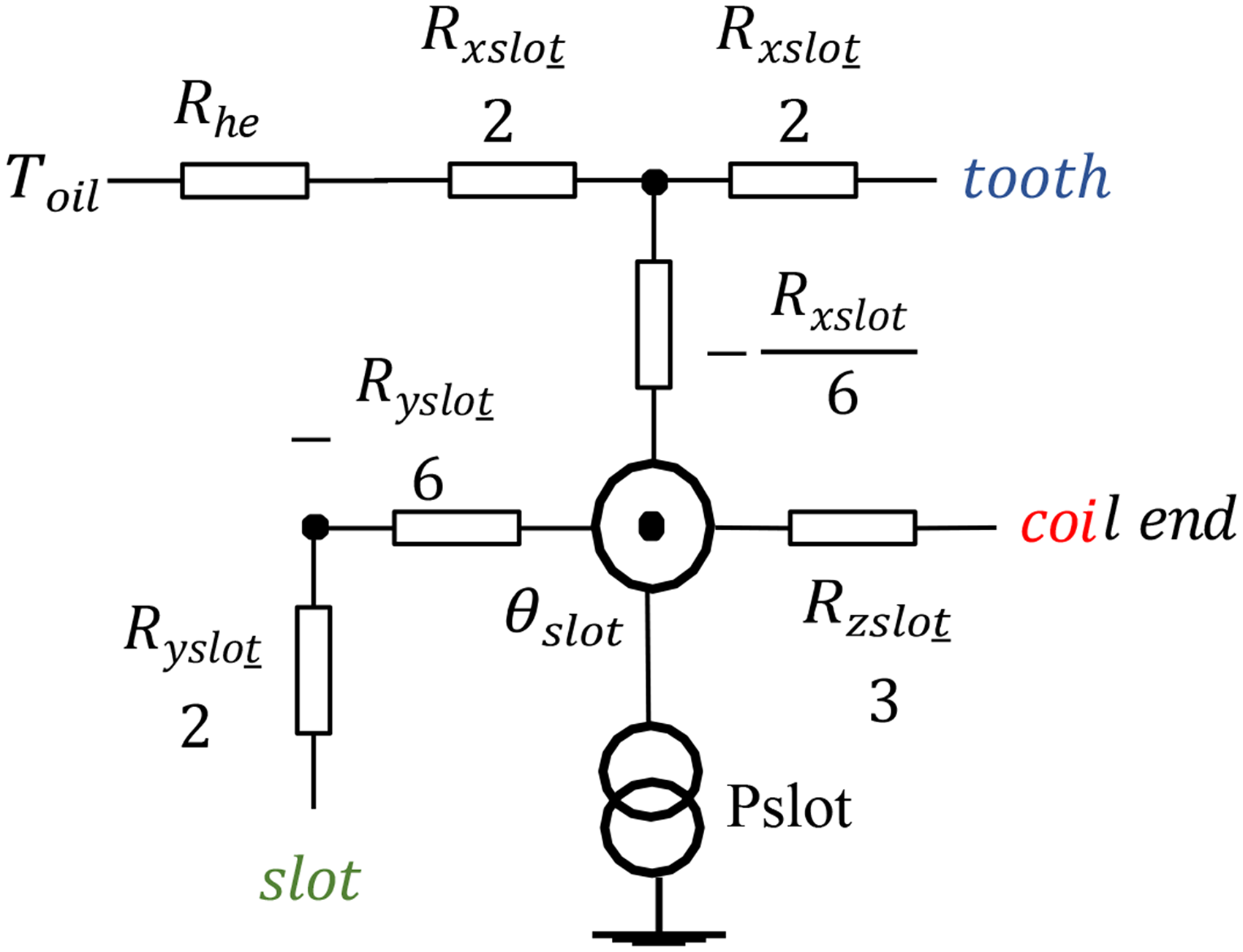
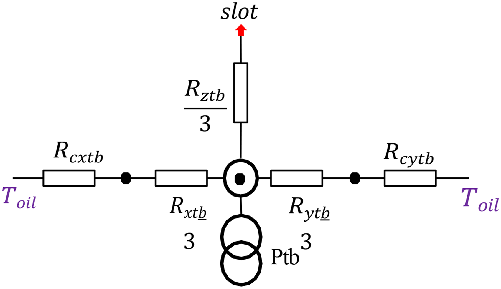
Thermal model of a slot with winding (heat transfer along X, Y, and Z).
Thermal model of the end coil (heat transfer along X, Y, and Z).
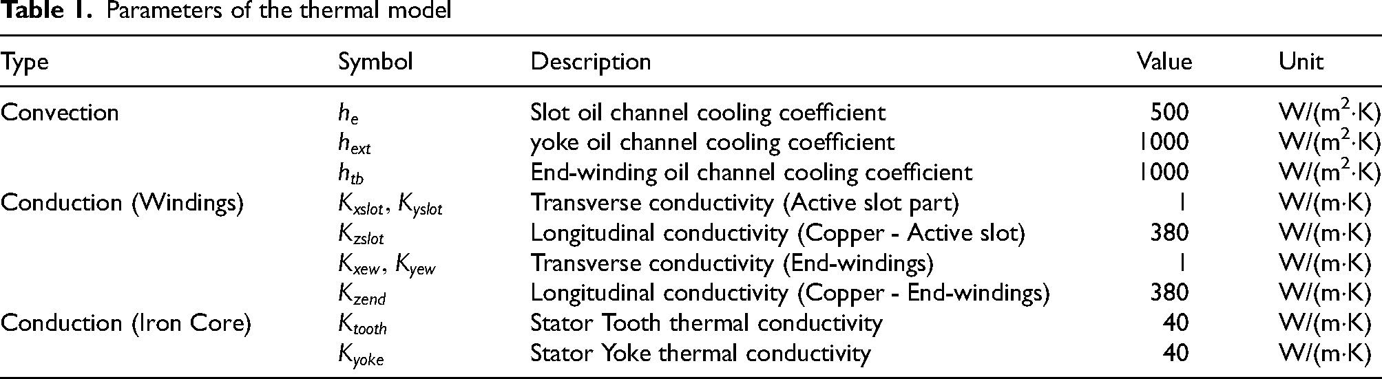
To obtain the complete thermal model of the machine, each block is interconnected by linking the corresponding nodes at the common surfaces of the different blocks. The thermal conductivities and convection coefficients are presented in Table 1.
Parameters of the thermal model
Electrical model
Power factor
The machine power factor is a key parameter in the overall optimization of the energy generation system, as it directly impacts the apparent power rating of the power electronics device associated with the generator (PWM rectifier). The generator current is regulated by the control system, which enforces phase alignment with the electromotive force (Id = 0 A control). This strategy maximizes the transfer of active power for a given current. In this framework, the generator phasor diagram is shown in Figure 7 (assuming R ≪ X, which is valid at high frequency), where X denotes the synchronous reactance of the machine.
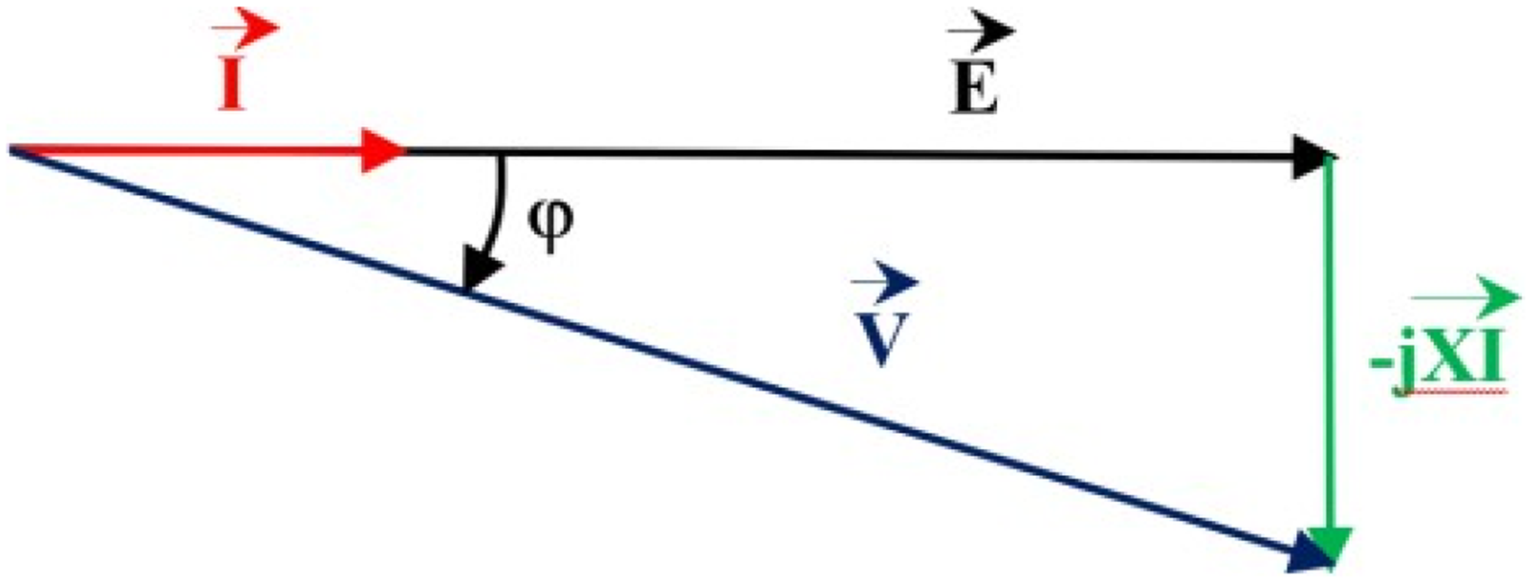
Phasor diagram of the generator with Id = 0 A control strategy.
The expression of the power factor is given as follows: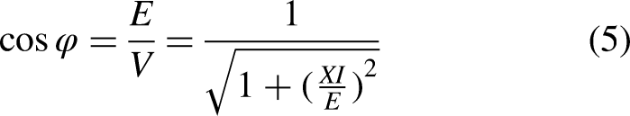
This expression shows that the higher the armature reaction, the lower the power factor. In any case, the value of the synchronous reactance X must be known in order to estimate the power factor and to account for it during the optimization process. The evaluation of the synchronous reactance requires knowledge of the machine inductance matrix, which enables the determination of the cyclic inductance.
The calculation of inductances depends on the type of winding (distributed or concentrated), the machine configuration (symmetric or asymmetric), and the slot geometry. A machine is symmetric when the phases are uniformly distributed at an angle of 2π/n, with n representing the number of phases. Conversely, an asymmetric machine groups several sets of circuits (e.g., three-phase or five-phase). For a symmetric machine, the inductance matrix is obtained by: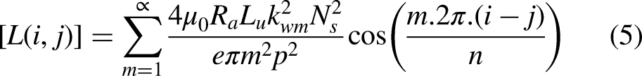
if (i = j),
For asymmetric machines, the expressions are detailed in. 12
To determine the leakage inductance per phase, only the slot leakage is considered. The classical assumption of an infinite permeability magnetic circuit is adopted. Open slots are assumed. Under these assumptions, the field lines are represented in Figure 8.
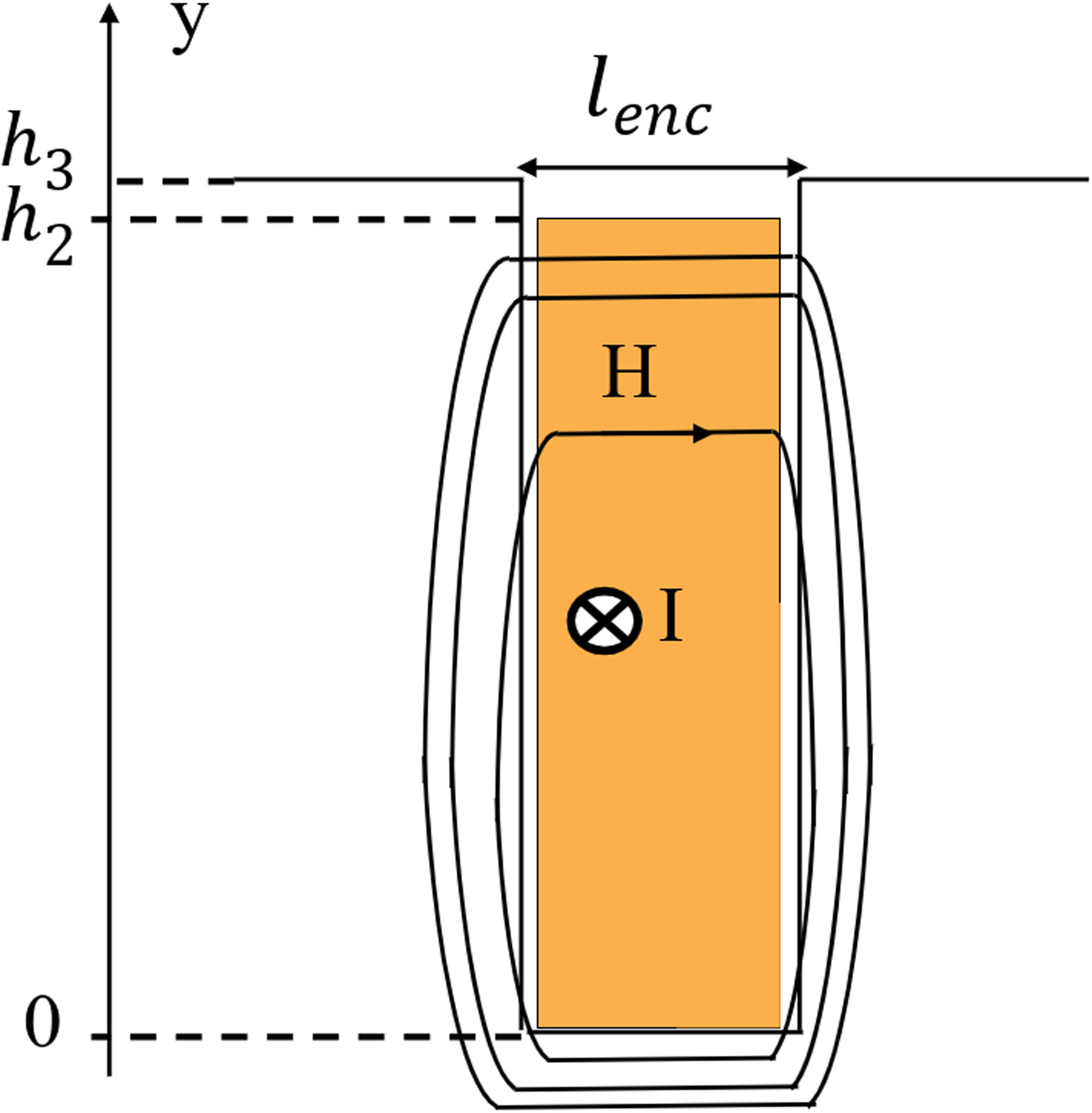
Model for the calculation of slot leakage inductance.
From the expression of the magnetic field in the slot and through a magnetic energy calculation, the expression of the leakage inductance per phase is obtained.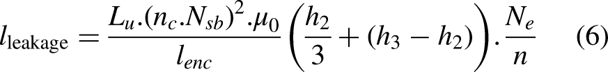
Loss calculation
One of the main challenges in the design process is the estimation of iron losses. As shown in Figure 1, the iron-cobalt alloy Vacoflux48 is considered for the stator laminations due to its high-frequency performance. The B(H) curve of this material is provided in.
13
Regarding the specific losses of Vacoflux48, which depend on the lamination thickness, the manufacturer provides data as a function of magnetic flux density and frequency. In this study, Vacoflux laminations with a thickness of 0.055 mm are considered, for which specific loss data can be found in.
14
For a flux density Bo = 2 T and 
The stator tooth losses are estimated from the following relation: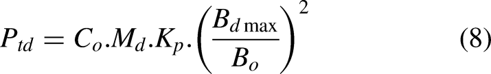
For the copper (Joule) losses in the windings, the following relation is applied (with coils made of Litz wire):
Machine optimization
The main objective is to minimize the mass of the active parts of the machine while satisfying the constraints defined in the specifications (maximum winding temperature, target efficiency, and power factor). The optimization is performed using the Genetic Algorithm (GA) solver from the MATLAB Global Optimization Toolbox. The problem involves 7 variables subject to 9 nonlinear inequality constraints.
To ensure convergence towards a feasible global optimum, the following configuration was adopted: a population size of 200 individuals with a maximum of 1000 generations. The selection was performed using selectionstochunif, and crossover using crossoverscattered. Crucially, the mutationadaptfeasible function was employed. This adaptive operator ensures that generated offspring satisfy the strict nonlinear constraints. While computationally intensive, resulting in approximately 20,000 function evaluations per generation to locate feasible regions, it guarantees the robustness of the solution. The process was accelerated using parallel computing (UseParallel) and monitored with a strict FunctionTolerance of 10−6 and a ConstraintTolerance of 10−4.
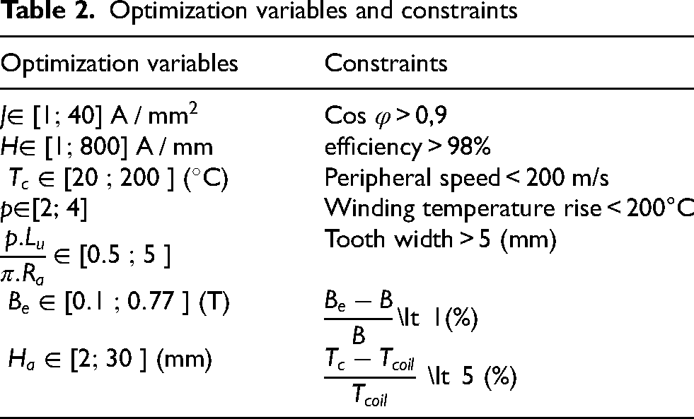
The study is first conducted for a three-phase machine with a diametral-pitch winding having 2 slots per pole and per phase. The optimization variables and constraints are listed in Table 2. The magnetic flux density in the teeth and yokes is limited to 2 T. The machine's pole count is restricted to p = 4 to keep the electrical frequency below 1000 Hz, in order to limit the PWM switching frequency and the associated power electronics switching losses.
Optimization variables and constraints
Results
Table 3 presents the values obtained for the variables after optimization. The high-performance cooling system studied in this work allows a current density of approximately 30 A/mm2 while maintaining an average winding temperature of 168°C. The pole count reaches its maximum value (p = 4) to minimize the machine mass. The RMS value of the magnetic flux produced by the magnets does not exceed 0.68 T (i.e., 0.96 T peak) for an acceptable magnet height. The specific power, considering only the active parts, reaches a remarkably high value of 29 kW/kg.
Optimization results
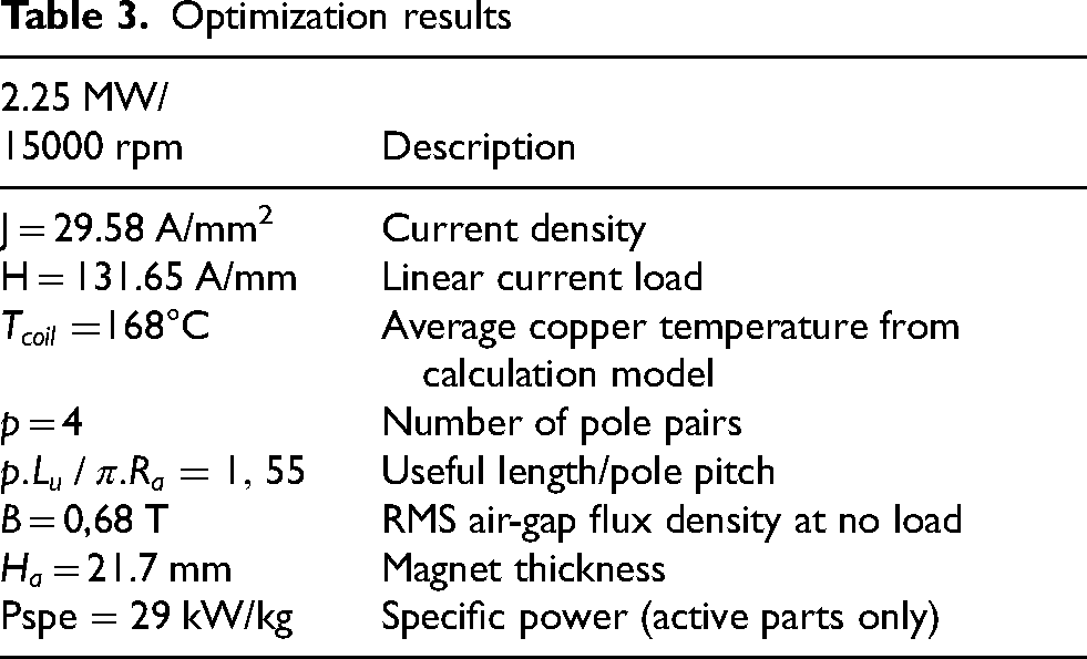
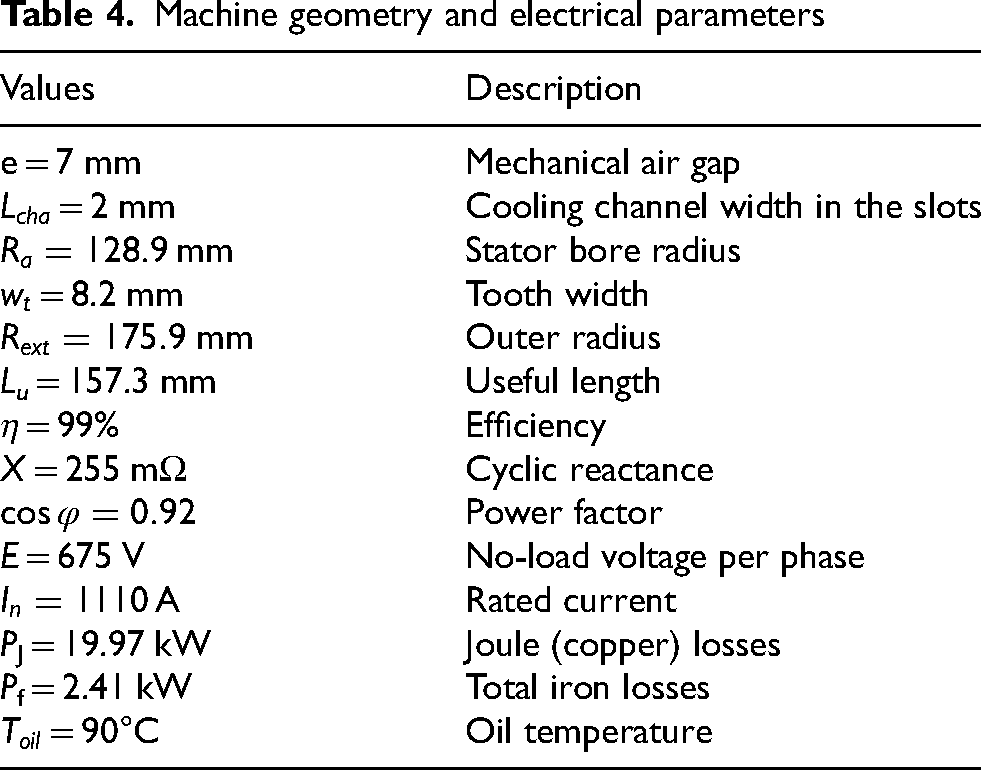
Table 4 provides some key values for the machine's geometric dimensions and electrical quantities.
Machine geometry and electrical parameters
Performance verification using finite element analysis
To validate the results obtained from the analytical modeling, we compared the performance of the optimized machine with those predicted by finite element models: the magnetic model (FEMM software) and the thermal model (COMSOL 3D).
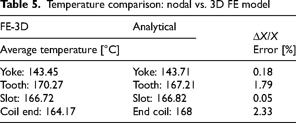
Figure 9 shows the temperature distribution in one stator tooth pitch. The boundary conditions are identical to those used in the nodal model (same heat transfer coefficients). The volumetric losses in the iron and the windings are taken from the optimization results. The average temperature values are reported in Table 5. The difference compared to the analytical model does not exceed 3%, which confirms the validity of the developed model.
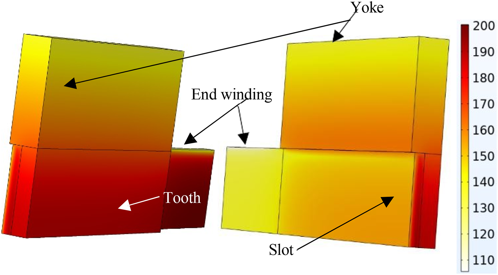
Temperature distribution in a stator tooth pitch (COMSOL 3D).
Temperature comparison: nodal vs. 3D FE model
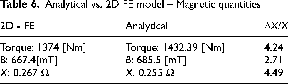
The flux density map under full-load conditions, obtained from the finite element model, is shown in Figure 10. This model incorporates the B(H) characteristic of Vacoflux48. The maximum flux density doesn’t exceed 2.2 T in the teeth. Table 6 shows that the analytical model predicts the machine performance with very good accuracy. The torque reduction observed in the 2D FE model is due to magnetic saturation of the tooth.
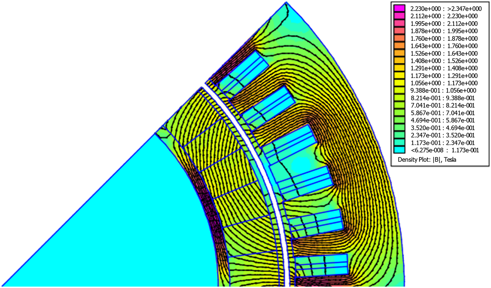
Flux density distribution – optimized machine (2D FE model).
Analytical vs. 2D FE model – Magnetic quantities
Multi-Star machine derived from an N-phase reference architecture
There are mainly two possible approaches for implementing a multiphase system based on a conventional architecture.15,16
Methode 1: Phase-shifted multiphase configuration
Starting from an n phase machine with an integer q, a
Six-phase (2 × 3) machine composed of two three-phase subsystems shifted by 30° electrical.
Methode 2: In-phase configuration
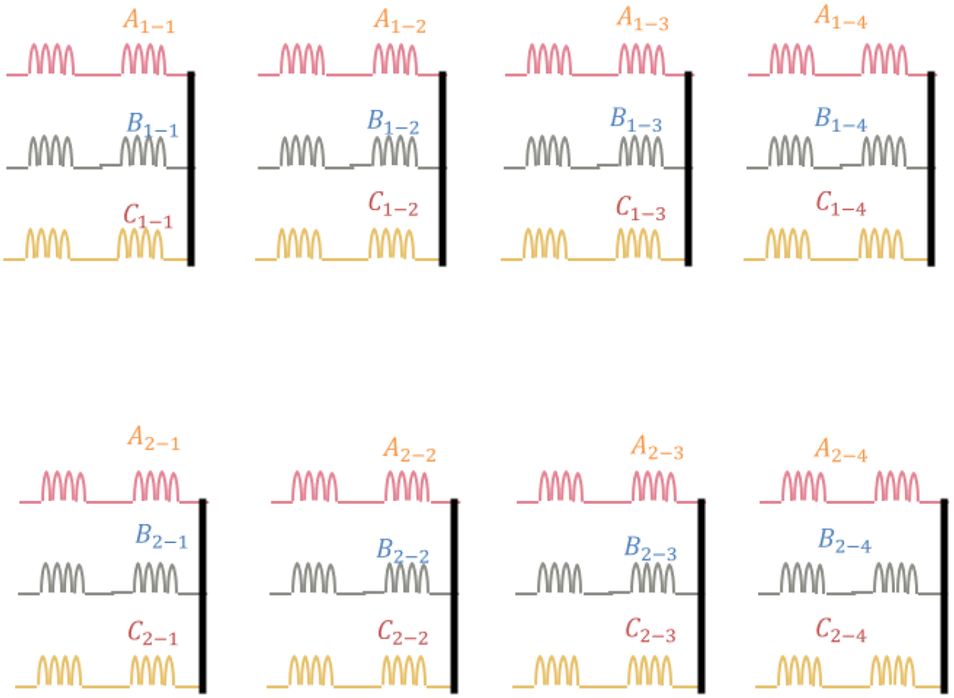
In the second approach, all electromotive forces (EMFs) are in phase. Here, the number of pole pairs must exceed one, while q can be either integer or fractional. The simplest configuration assigns one pole pair per n subsystem, providing spatial separation and reduced magnetic coupling. Variants with two or more pole pairs can also be implemented depending on the desired EMF characteristics. Moreover, coils may be distributed across different pole sectors to achieve specific EMF patterns. A combination of both methods is also possible, provided that q is an integer, offering additional design flexibility and multiple feasible topologies (Figure 12).
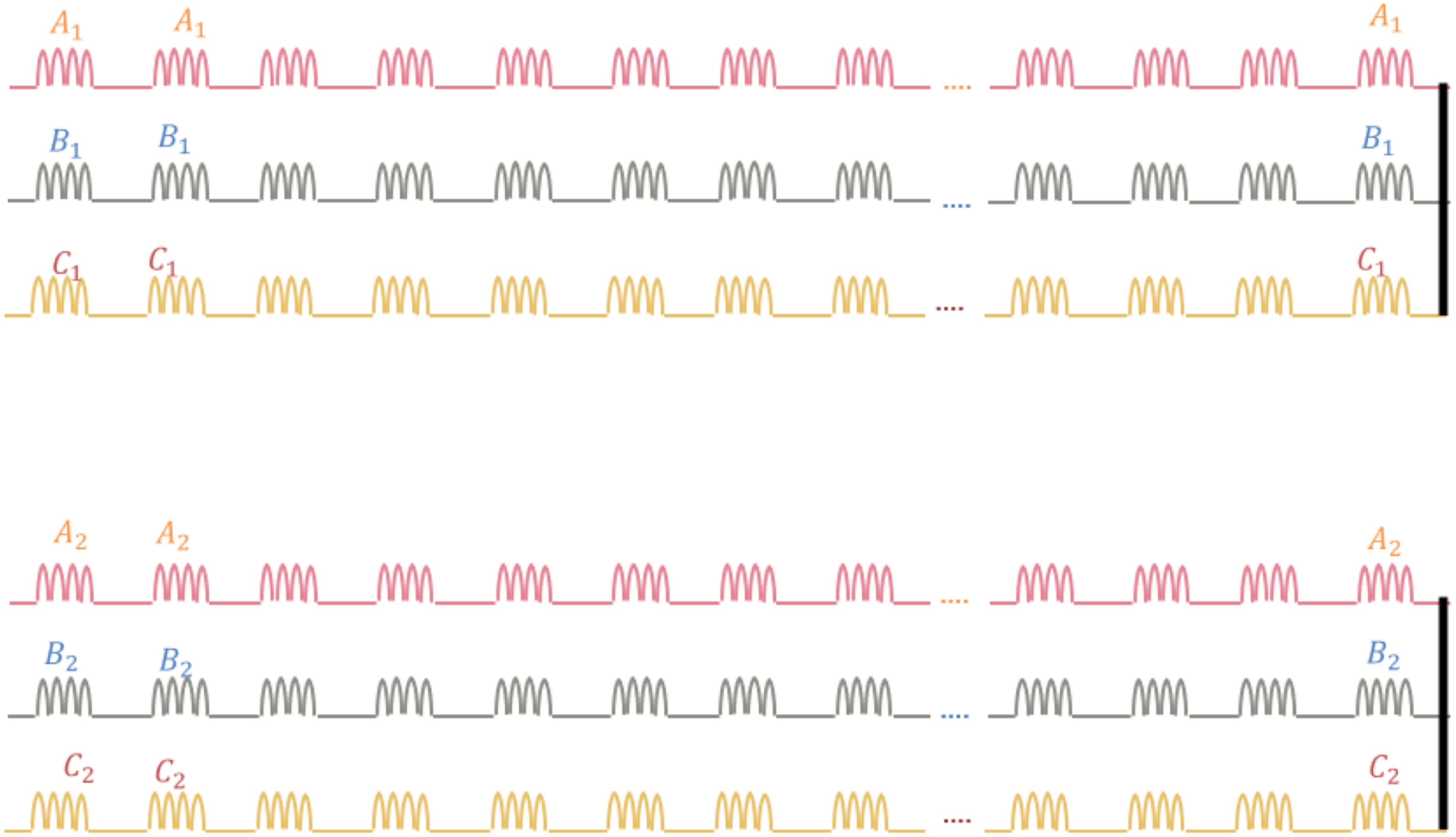
24-Phase machine topology: double 12-phase system structured as eight star-connected three-phase subsystems with 30° inter-group shift.
Consideration of fault tolerance
Three-phase short-circuit current tolerance
The three-phase short-circuit current in the machine, in the case where the synchronous impedance X 
To prevent excessive winding temperature, rise and potential machine degradation due to internal short circuits, the short-circuit current
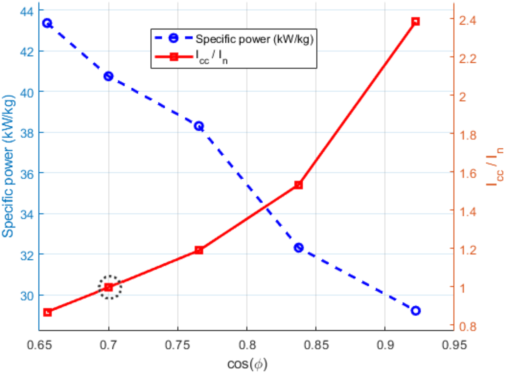
Variation of specific power and short-circuit as a function of the power factor.
The selection of the optimal operating point directly depends on the user's design priorities:
If priority is given to fault tolerance, it is recommended to bring the short-circuit current This condition corresponds to a low power factor (typically around 0.7), which consequently requires oversizing of the power electronics. If the objective is to achieve a high-power factor and minimize the absorbed current, this implies accepting a short-circuit current higher than the nominal current ( In this case, a dynamic reconfiguration strategy is required in the event of a fault to protect the machine. In certain cases, a compromise can be reached, for instance by limiting
This approach involves accepting a temporary thermal rise in the windings during fault conditions, while ensuring a sufficient thermal margin under nominal operation, for example, by limiting the maximum copper temperature to between 150°C and 170°C in the present case.
This analysis highlights the importance of jointly considering electrical and thermal constraints during the machine optimization process to ensure reliable and efficient operation.
Influence of the number of phases
Increasing the number of phases is beneficial for fault tolerance. In this section, the combined influence of the number of phases n and q on the machine's specific power is analyzed. Several configurations were evaluated while maintaining the same stator and rotor topology as previously presented. For each configuration, an independent optimization was carried out, incorporating the predefined design constraints. Table 7 summarizes the corresponding results.
Optimization results for various n and q
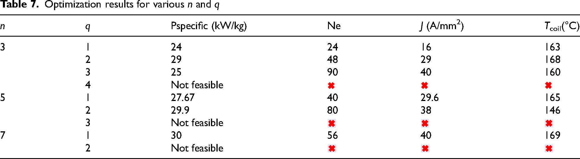
The results show that, for the machine under study, a
Conclusions
This paper has presented a comprehensive analytical methodology for the design and optimization of electrical machines, combining electromagnetic and thermal analytical models. The study also introduced and compared different
The influence of key design parameters particularly the number of phases (n) and the number of slots per pole per phase (q) on the machine's specific power density was analyzed. A central focus was placed on the impact of
The choice of the optimal operating point therefore depends on application priorities:
Future work will focus on a more detailed analysis of the
Footnotes
Funding
The authors disclosed receipt of the following financial support for the research, authorship, and/or publication of this article: This work was supported by the Université de Lorraine,
Declaration of conflicting interests
The authors declared no potential conflicts of interest with respect to the research, authorship, and/or publication of this article.