
Abstract
Objective
To address increased motor losses and severe heating caused by high tooth harmonics in high-voltage multi-pole asynchronous motors for nuclear power plants.
Methods
A no-load loss calculation model considering higher-order harmonics is proposed for high-voltage multi-pole asynchronous motors. Rotor iron loss and no-load rotor copper loss are separated from additional losses, and stator and rotor iron loss models and a rotor copper loss model are established by considering the skin effect, rotational magnetization, and magnetic-material nonlinearity. The model is verified by asynchronous-motor no-load tests. To reduce the complexity and sample incomparability caused by direct mixed optimization of rotor slot number and slot dimensional parameters, a hierarchical optimization method is developed. The proposed loss model is first used to quantitatively screen the optimal slot combination, after which the continuous structural parameters are further optimized using the genetic algorithm in the optiSLang platform to obtain the final optimized motor design.
Conclusions
The proposed model achieves a relative error of 7.8% compared with experimental results. The 76-slot rotor scheme reduces the no-load loss by 5211.4 W compared with the original 108-slot rotor scheme. Further optimization improves motor efficiency by 1.78%, demonstrating the calculation accuracy of the proposed no-load loss model and the effectiveness of the hierarchical optimization method.
Keywords
Introduction
Asynchronous motors, known for their simple structure and reliable operation, are commonly used as drive motors for nuclear power plant compressors. Their stable operation directly affects the safety and efficiency of the entire system. To simplify the mechanical structure of the nuclear power plant compressor transmission system, reduce the gearbox reduction ratio, and improve system reliability and operational efficiency, an increase in the pole number of asynchronous motors is required. Additionally, to enhance motor output torque and reduce copper consumption in the windings, it is necessary to increase the voltage level of the motor and adopt an open-slot structure. As a result, the drive asynchronous motors in nuclear power plant compressor systems are often designed with a high-voltage multi-pole structure. However, increasing the pole number and widening the slot openings significantly elevate the tooth harmonic content in the air-gap magnetic field, severely impacting motor efficiency and operational reliability. Therefore, accurately calculating the no-load losses of high-voltage multi-pole asynchronous motors and improving their operational efficiency are of great importance for ensuring the safety of nuclear power plants.
Therefore, before motor manufacturing, loss models are commonly employed to calculate motor performance for evaluating the feasibility of design schemes, enabling timely adjustments to the design. This approach effectively mitigates R&D risks and avoids resource wastage. In, 1 a segregated core loss model suitable for induction motors is proposed. This model is applicable to distorted flux density conditions and can separate eddy-current losses, hysteresis losses, and excess losses. In, 2 a method for determining the no-load losses of PWM-fed induction motors is introduced, where the motor's no-load losses are calculated by summing the losses derived from orthogonal decomposition of flux density. In, 3 an approximate core loss calculation model based on 2D and 1D finite element methods is proposed, which extracts harmonic components affecting induction motor losses and thereby reveals the factors influencing motor loss. After evaluating the motor losses, multi-objective optimization of the motor is further required to enhance its performance. In, 4 the efficiency of a 37-kW squirrel-cage induction motor under sinusoidal and nonsinusoidal supply conditions is investigated. Motor losses are evaluated using both the IEC loss segregation method and finite-element simulation. The results show that the simulated total losses agree well with the measured values, although discrepancies remain among individual loss components. In, 5 a segmented iron loss model is developed with coefficients that vary according to the amplitude and frequency of the magnetic flux density. To account for the nonlinear behavior of magnetic materials under harmonic excitation, two supplementary flux-density-related terms are incorporated into the conventional iron loss formulation, and the correctness of the proposed model is verified through experiments. In, 6 an iron loss estimation method for rotating machines is proposed. In this method, eddy-current loss is calculated through nonlinear time-domain electromagnetic field analysis, while hysteresis loss is estimated by considering the flux distribution along the thickness of the steel sheet. The method can accurately evaluate high-frequency harmonic losses with only a limited number of material constants, and its validity is verified through experiments on ring specimens and several types of motors. Currently, multi-objective optimization of motors is conducted using optimization algorithms to handle the constraints among multiple objectives and identify the optimal motor parameters for achieving the best performance scheme. 7 Among these algorithms, the genetic algorithm (GA), as an efficient, parallel, intelligent stochastic search algorithm, is widely used in motor optimization due to its ability to address various mathematical problems and handle different objective functions and constraints. With the continuous development of motor optimization design and computer technology, numerous improved genetic algorithms have emerged. In, 8 a control-vector enhanced genetic algorithm (CVEGA) is proposed for dynamically optimizing fitness function landscapes and chromosome encoding configurations, and this approach can be extended to prevent premature convergence while achieving high-precision global minima with reduced computational overhead. In, 9 a hybrid genetic algorithm based on information entropy and game theory is introduced to overcome the tendency of traditional genetic algorithms to fall into local optima. Compared with conventional genetic algorithms, this method demonstrates superior performance, higher optimization capability, improved solution accuracy and stability, and faster convergence speed. In, 10 a hybrid grasshopper-genetic algorithm is proposed for combining grasshopper optimization algorithm (GOA) and genetic algorithm (GA), and this method can be extended to achieve faster convergence and escape local optima effectively. In, 11 a hybrid algorithm integrating particle swarm optimization (PSO) and genetic algorithm (GA) is proposed. Compared to the conventional GA, this hybrid approach demonstrates enhanced global search capability and accelerated convergence by synergizing the strengths of both algorithms. In, 12 a novel and easily implementable Multi-Task Genetic Algorithm (MTGA) is proposed for effectively handling multi-objective optimization problems, and this method can be extended to significantly improve efficiency across diverse tasks. In, 13 a non-dominated sorting genetic algorithm (NSGA-II) is applied to multi-objective optimization of five-phase induction motors, and this approach can be extended to asynchronous motors with more phases. In, 14 a multi-physics field collaborative optimization design method for asynchronous motors based on genetic algorithms is proposed. This method comprehensively considers multiple complex factors, including stator-rotor topology, efficiency, and power factor, enabling fast and effective optimization of asynchronous motors. Based on the above literature, existing induction motor loss models generally neglect additional losses. For high-voltage multipole induction motors affected by higher-order harmonics, classifying rotor iron loss and rotor copper loss as additional losses may lead to inaccurate performance evaluation and optimization results. Meanwhile, the genetic algorithm optimizations in the above studies were all conducted under fixed motor slot combinations, lacking discussion of other slot combination schemes.
In response to the above issues, this paper proposes a no-load loss calculation model for high-voltage multi-pole asynchronous motors, establishing models separately for stator iron loss, rotor iron loss, and no-load rotor copper loss. The loss model fully considers the impact of stator and rotor tooth harmonics on losses, and its accuracy is validated through comparative experimental results. Based on this loss calculation model, the quantitative effects of major motor structural parameters on no-load losses are analyzed to determine key optimization variables. Furthermore, this paper proposes a hierarchical optimization method. The proposed no-load loss model is used to calculate different slot combination schemes, thereby rapidly screening out the optimal slot combination scheme. On this basis, Latin hypercube sampling is adopted to establish the sample space of motor optimization variables, and the genetic algorithm in the optiSLang platform is used to optimize the motor. This method addresses the coupling conflicts among motor optimization variables and improves the efficiency of the optimization process.
Establishment of the high-voltage multi-pole asynchronous motor model
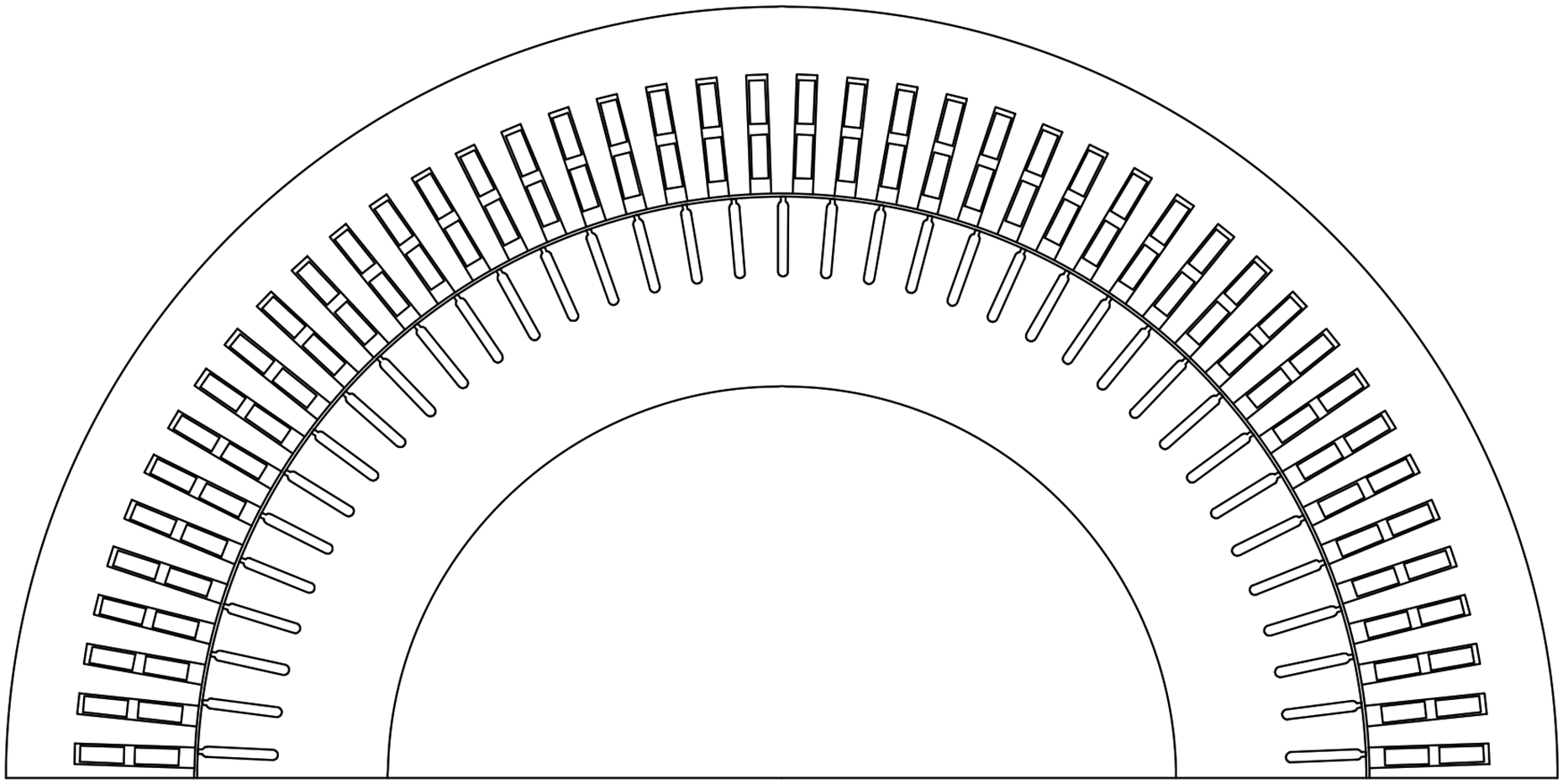
The initial design is a three-phase 10-pole asynchronous machine suitable for low-speed and high-torque operating conditions. The topological structure of the machine and its fundamental parameters are shown in Figure. 1 and listed in Table 1, respectively.
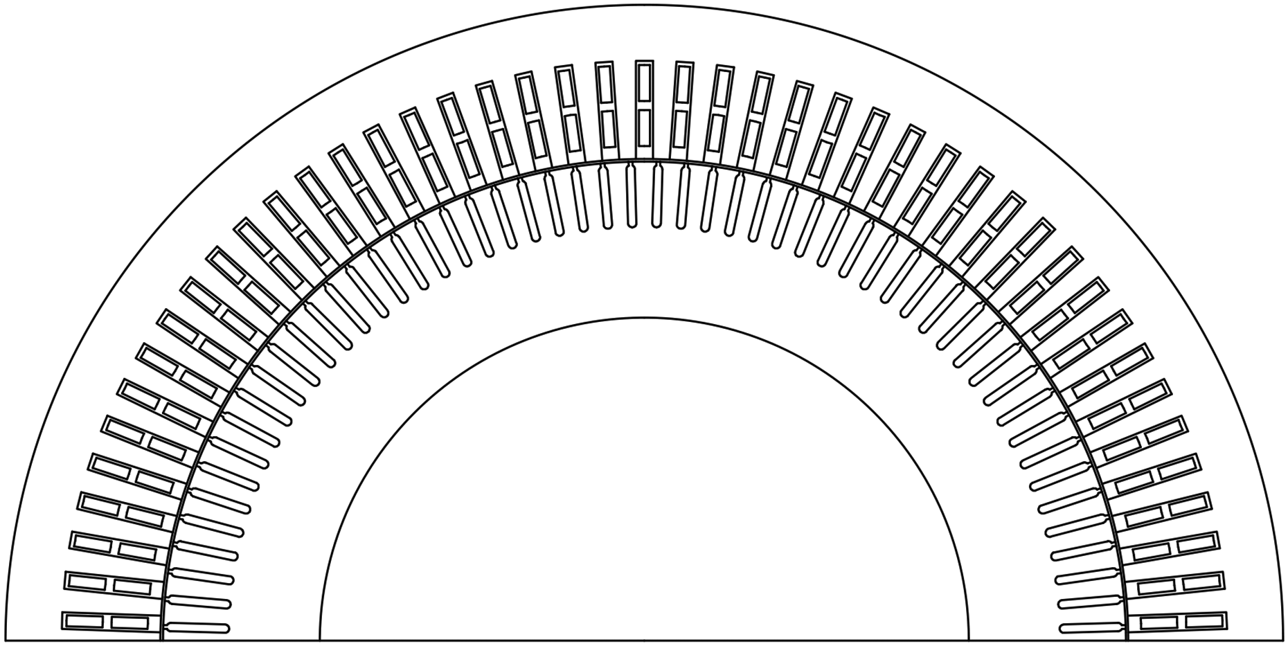
YB2 560-10 asynchronous motor diagram.
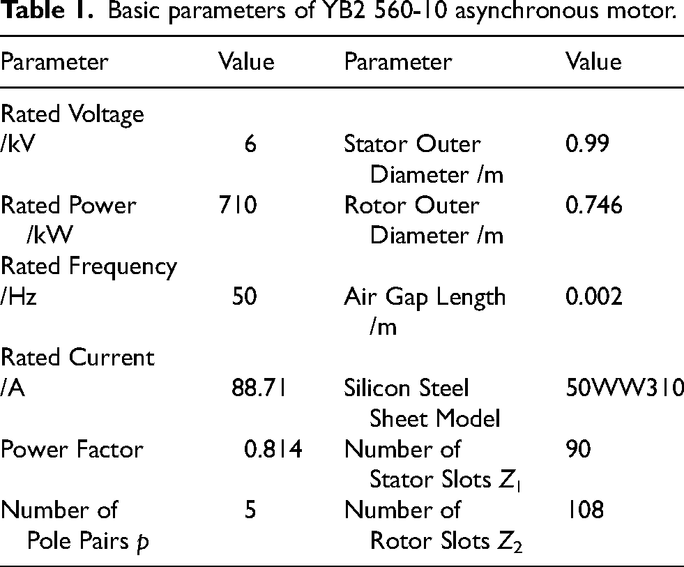
Basic parameters of YB2 560-10 asynchronous motor.
No-load magnetic field analysis of the motor
This section establishes the field-circuit coupled time-stepping finite element model for the YB2 560-10 high-voltage multi-pole asynchronous motor,
15
as shown in equation (1), and performs a no-load simulation of the motor.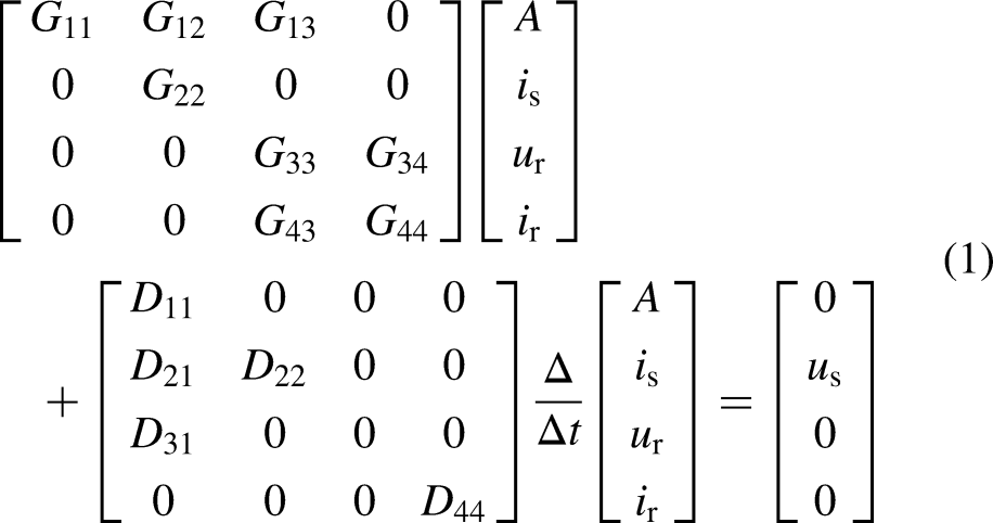
where
The no-load air-gap flux density waveform of the machine and its harmonic components are presented in Figure. 2 and Figure. 3 respectively. As shown in Figure. 3, the higher-order harmonics in the air-gap flux density are predominantly first-order and second-order stator tooth harmonics. Among the first-order tooth harmonics, the amplitudes of the 17th and 19th order harmonics measure 0.23 T and 0.137 T respectively, while the second-order tooth harmonics exhibit amplitudes of 0.193 T and 0.041 T for the 35th and 37th order harmonics. This analysis demonstrates that high-voltage multi-pole asynchronous machines inherently contain substantial higher-order harmonic components in their no-load air-gap flux density. Consequently, it is imperative to perform accurate calculations of no-load losses in such machines and systematically investigate critical factors affecting the operational efficiency of the machine.
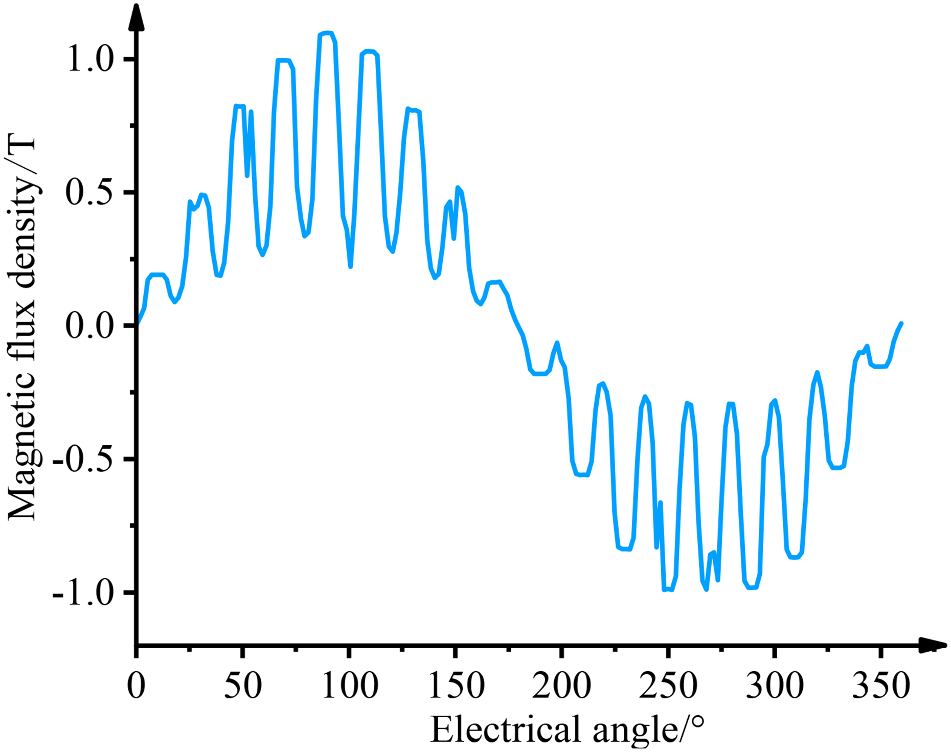
No-load air-gap magnetic flux density diagram of the motor.
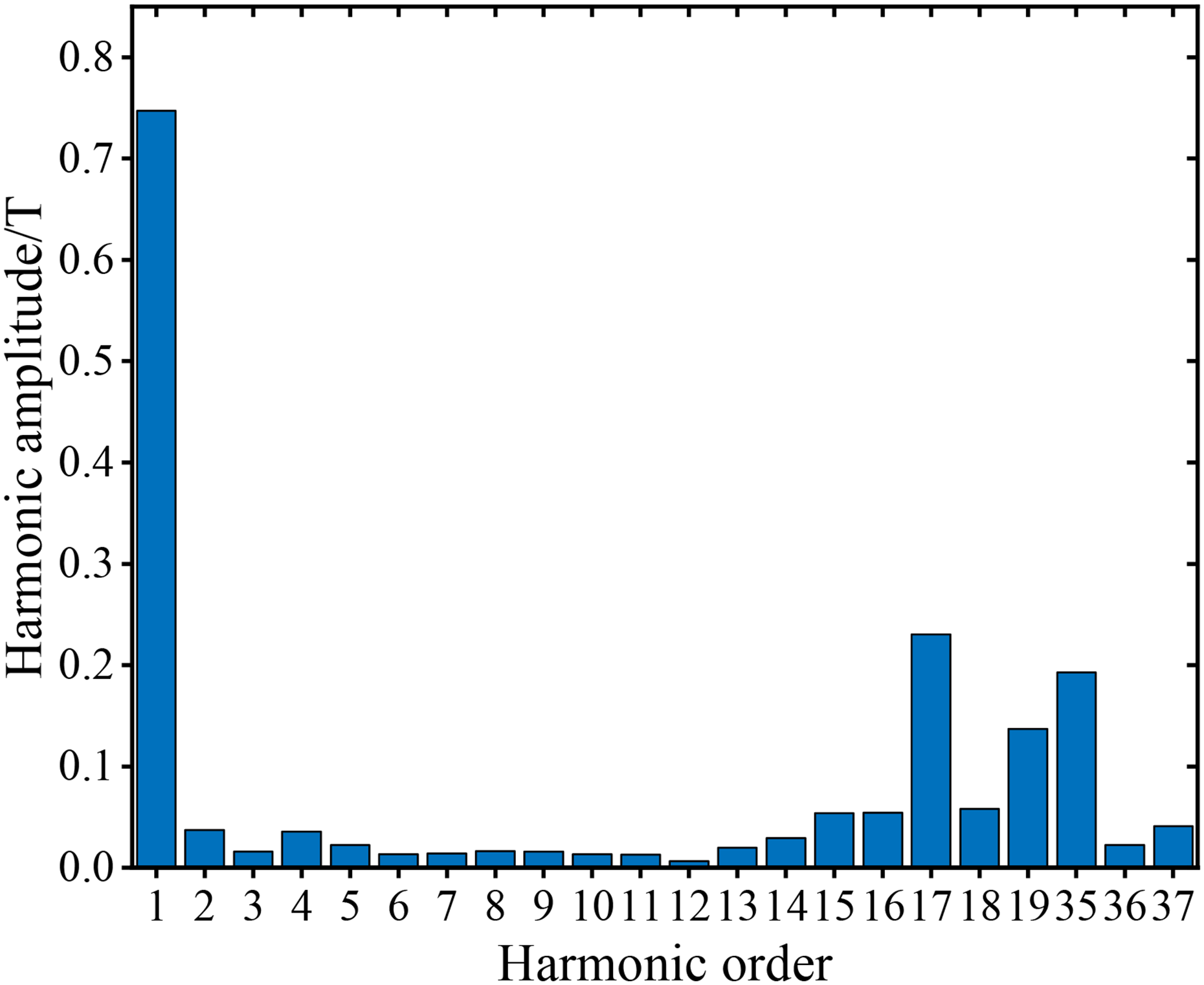
Air-gap magnetic field harmonic content.
No-load loss calculation model of high-voltage multi-pole asynchronous motor
The calculation model for the no-load loss of a conventional asynchronous motor
16
is shown in equation (2).
where pcu1 is the copper loss of the stator windings; pmec is the mechanical loss; pFe1 is the stator core loss; pad is the additional loss, typically taken as 0.5% of the rated input power of the motor.
For high-voltage multi-pole asynchronous motors, significant high-order harmonics in the air-gap magnetic field will cause a substantial increase in rotor core loss pFe2 and rotor copper loss pcu2 under no-load conditions. If pFe2 and pcu2 are roughly combined into the additional loss, it will result in inaccurate no-load loss calculations and prevent a quantitative analysis of how each optimization variable affects pFe2 and pcu2, leading to inaccurate optimization solutions. Therefore, this paper proposes a no-load loss calculation model for high-voltage multi-pole asynchronous motors, as shown in equation (3).
Based on the aforementioned analysis, this paper establishes a variable-coefficient segmented core loss calculation model and proposes a discretized rotor copper loss calculation model based on the time-stepping finite element method with individual conductor bar elements as the research objects. This approach enables accurate calculation of core losses and no-load rotor copper losses in high-voltage multi-pole asynchronous motors.
Stator and rotor iron loss calculation model
The traditional classical three-term constant coefficient iron loss calculation model
17
is shown in equation (4).
where ph is the hysteresis loss; pe is the eddy current loss; pa is the additional loss; kh is the hysteresis loss coefficient; ke is the eddy current loss coefficient; ka is the additional loss coefficient; α is a constant coefficient fitted from the silicon steel sheet under a certain magnetic flux density and frequency; f is the alternating frequency.
First, an improved eddy current loss coefficient ke(f) varying with harmonic frequency is introduced into the conventional core loss model to replace the constant ke, thereby accounting for the influence of the skin effect on eddy current losses under high-order harmonic flux density and variations in eddy current loss per unit weight of silicon steel laminations. The modified coefficient is expressed in the form of an alternating function,18,19 as shown in equation (5).
where d, σ, ρ and μ are the thickness, the electrical conductivity, the density and the average magnetic permeability of the silicon steel sheet.
Next, a hysteresis loss compensation term khBαf(k1Bc) is introduced to replace khBαf, in order to compensate for the increase in hysteresis loss caused by high-order harmonic magnetic flux density.
20
The iron loss model with the compensation term is shown in equation (6).
Finally, considering the losses caused by rotational magnetization, a rotational magnetization coefficient kr is introduced to account for the changes in hysteresis, eddy current, and additional losses caused by rotational magnetization. The variation of the rotational magnetization coefficient is related to the ellipticity δ of the magnetic flux density vector trajectory, which can be calculated using equation (7). Since the maximum magnetic flux density |Bmax| in the stator core is much larger than the minimum magnetic flux density |Bmin|, the ellipticity is mostly less than 0.1, and it can be approximated that the rotational magnetization coefficient kr = 1 + δ.
21
where Bmax is the major axis of the magnetic flux density vector trajectory; Bmin is the minor axis of the magnetic flux density vector trajectory.
Considering the effects of high-order harmonic magnetic flux density skin effect and rotational magnetization on high-voltage multi-pole asynchronous motors, this paper establishes a variable coefficient segmented iron loss calculation model to accurately calculate the stator and rotor core losses of the motor, as shown in equation (8).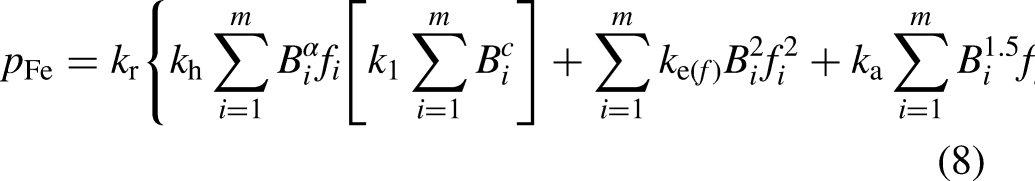
No-load rotor copper loss calculation model
The current density distribution in rotor bars under no-load conditions is shown in Figure. 4, where the current density near the slot opening region shows significantly higher values compared to other positions, with the maximum unit density reaching 3.18 × 10⁷ A/m2. To address the skin effect in rotor bars, this paper employs the time-stepping finite element method. By analyzing current density and eddy current loss in individual bar elements, a calculation model for no-load rotor copper loss is formulated with single bar elements as the research object, as expressed in equation (9).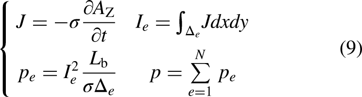
Current density distribution of the motor no-load rotor bars.
where σ is the electrical conductivity of the rotor bar; Az is the axial component of the magnetic vector potential of the rotor bar; J is the eddy current density; Ie is the current of the element; pe is the loss of the element; Lb is the axial length of the bar; Δe is the area of the e-th element; p is the loss of a single rotor bar; N is the total number of elements in a single rotor bar.
Analysis of the motor no-load test results
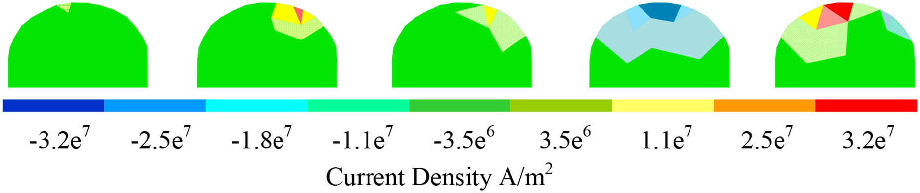
To verify the accuracy and effectiveness of the no-load loss calculation model proposed in this paper, a no-load test was conducted on the YB2 560-10 asynchronous motor. The test setup is shown in Figure. 5.
Field test setup of the asynchronous motor.
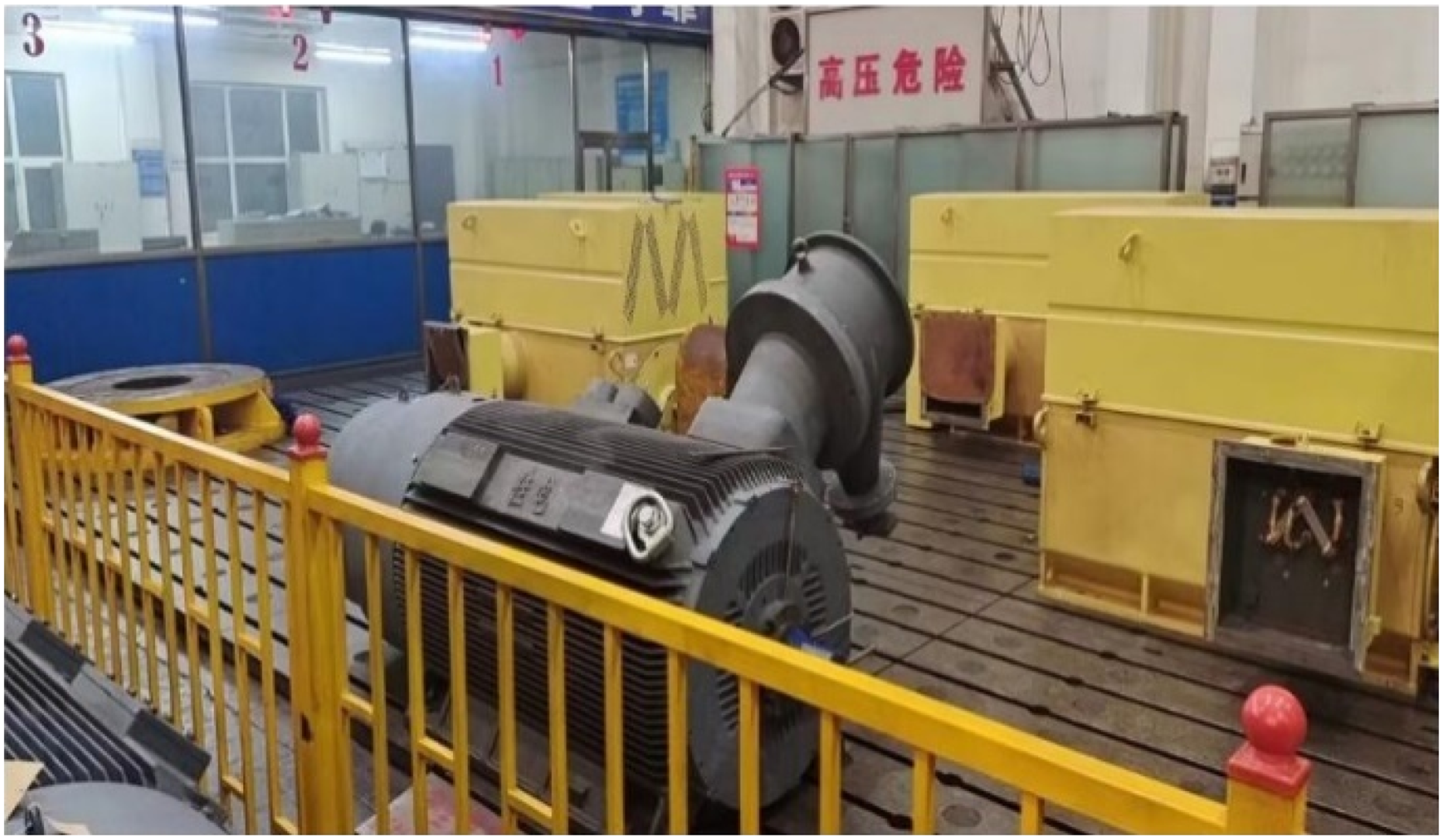
Before the experiment, the stator winding of the motor was connected in a Y-type configuration. The wiring diagram for the motor no-load test is shown in Figure. 6.
Motor wiring diagram.
The motor shaft was kept free of load, and the AC voltage regulator was adjusted to the minimum voltage position before powering on. The rotation direction of the motor rotor was observed to ensure compliance with requirements. Next, the voltage applied to the stator winding was adjusted to allow the motor to operate at rated voltage and rated frequency until the motor speed stabilized. The terminal voltage was then gradually reduced from (1.1∼1.3) UN until a noticeable change in motor speed occurred. During this process, the no-load power, no-load current, and terminal voltage were recorded. Based on the recorded data, the no-load characteristic curve of the motor was plotted, as shown in Figure. 7.
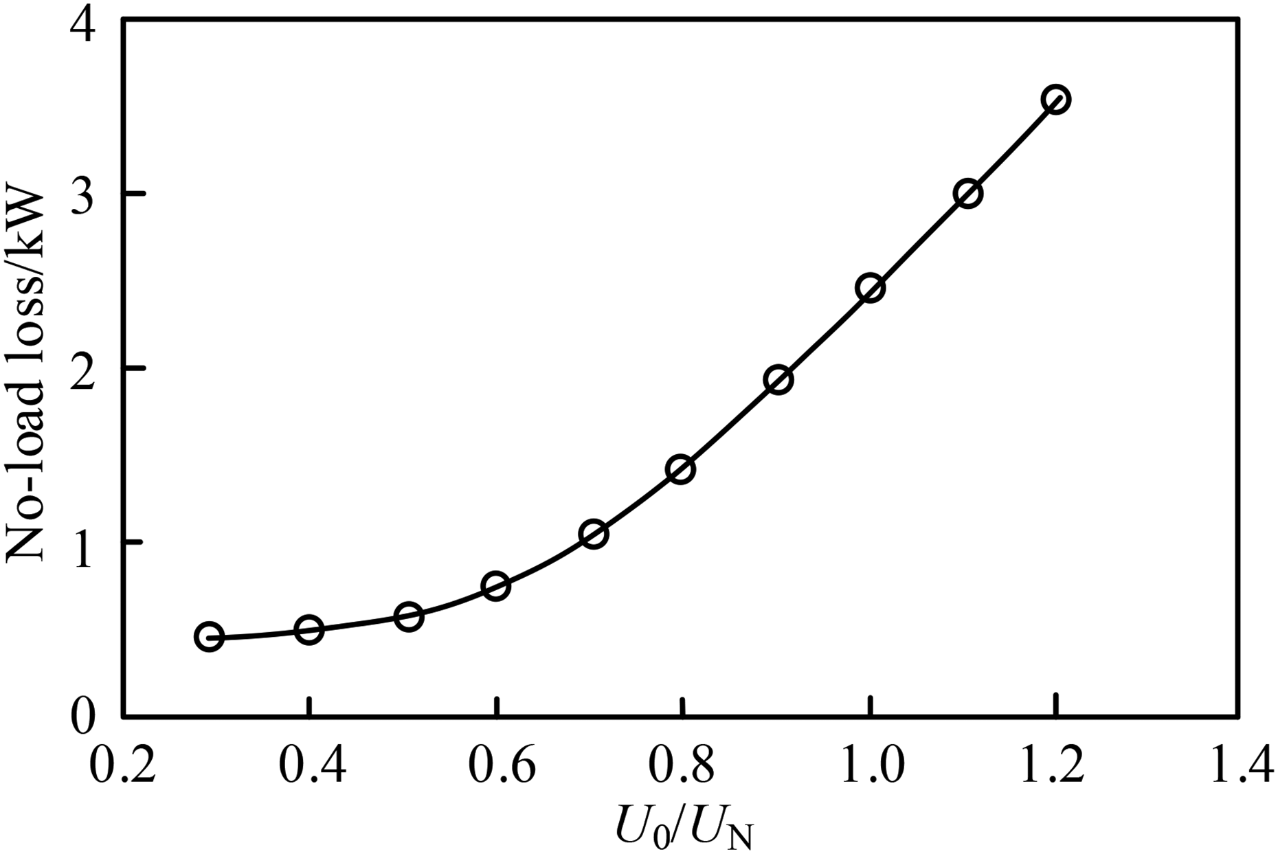
Motor no-load characteristic curve.
During the experiment, the no-load current of the motor was measured using a digital oscilloscope, and the results are shown in Figure. 8. The simulation results of the no-load current of the motor are shown in Figure. 9.
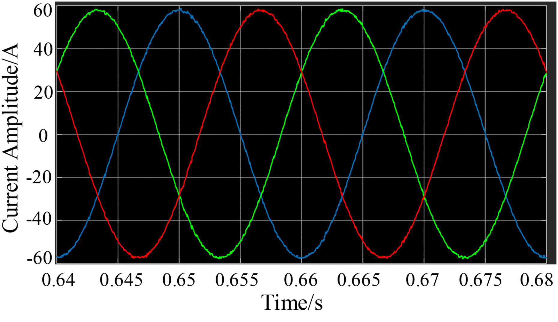
Motor no-load experimental current.
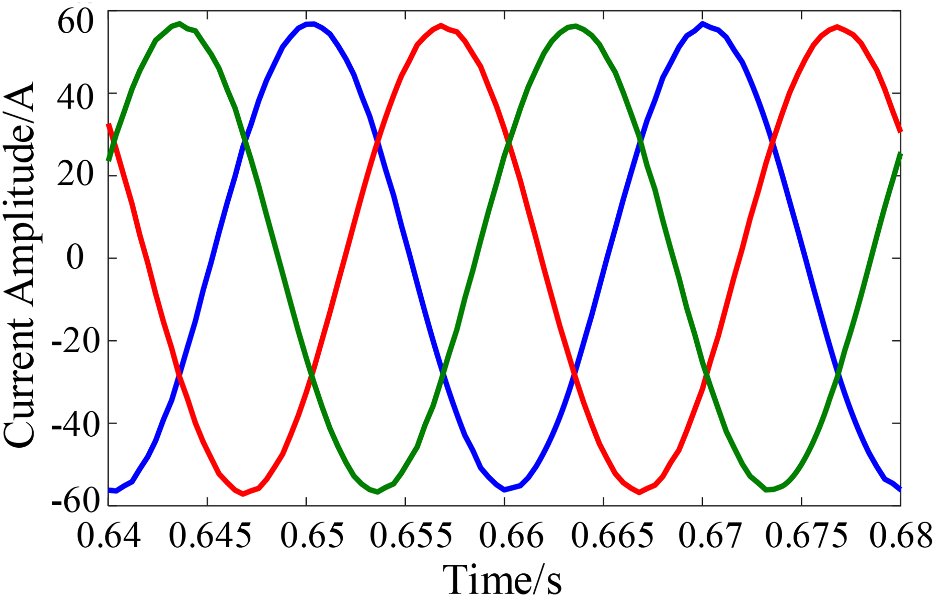
Motor no-load simulated current.
By analyzing the two figures, it can be observed that the experimentally measured no-load current amplitude of the motor is 57.6 A, while the simulated no-load current amplitude is 56.82 A, resulting in an error of 1.35%.
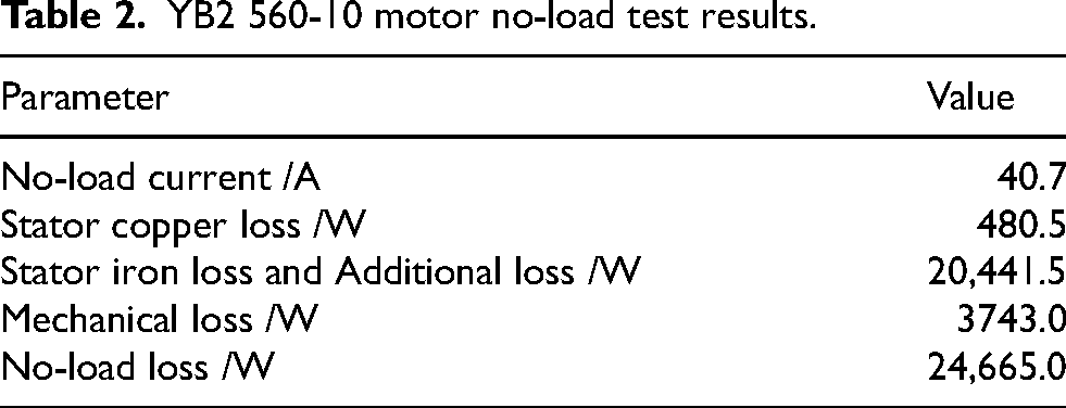
The no-load experimental results of the motor are shown in Table 2. Since the motor speed remains constant, the mechanical losses are independent of the terminal voltage. Based on the experimental no-load characteristic curve of the motor, the mechanical loss can be separated. The separated mechanical loss is 3743 W. The measured no-load current of the motor is 40.76 A, and the no-load stator copper loss of the motor can be calculated from the no-load current, with a calculated value of 480.5 W. However, the iron loss and the additional loss under no-load conditions are coupled together and cannot be separated solely through the no-load test. Therefore, the sum of additional loss and iron loss is obtained by subtracting the calculated stator copper loss and the separated mechanical loss from the no-load loss. The sum of additional loss and iron loss is 20,441.5 W.
YB2 560-10 motor no-load test results.
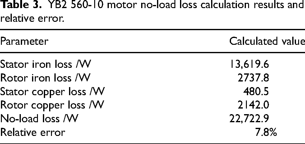
The calculated results and relative errors of the motor no-load loss are shown in Table 3. Analysis of Table 3 and Table 2 reveals that the no-load losses of the machine measure 24,665 W, while the calculated value of no-load losses for the machine is 22,722.9 W, resulting in a relative error of 7.8%. This computational relative error falls within the acceptable engineering tolerance range, which validates the effectiveness of the no-load loss calculation model.
YB2 560-10 motor no-load loss calculation results and relative error.
The impact of slot combination on the no-load losses of high-voltage multi-pole asynchronous motors
The slot combination significantly influences motor efficiency, losses, and torque ripple performance. For a 10-pole 90-slot stator configuration, rotor slot numbers of 74, 76, 104, 106, 110, and 112 are recommended to suppress parasitic torque, 22 while other slot numbers may adversely affect motor performance. Due to the discrete nature of rotor slot numbers and their strong coupling constraints with slot parameters, where different rotor slot numbers correspond to distinct boundary conditions for slot parameters, this study treats rotor slot numbers as an independent optimization variable for conducting optimization analysis on high-voltage multi-pole asynchronous motors. Six rotor slot combinations (74, 76, 104, 106, 110, 112 slots) are analyzed to assess slot number effects on air-gap harmonic flux density and motor no-load losses.
With rotor slot parameters held constant, Figure. 10 shows stator tooth harmonics remain stable across slot numbers, while rotor tooth harmonics vary significantly. When the rotor slot number is 110, the first-order rotor tooth harmonic amplitude is the smallest, with the 21st harmonic flux density being 0.01456 T and the 23rd harmonic flux density being 0.01 T. When the rotor slot number is 76, the second-order and third-order rotor tooth harmonic amplitudes are the smallest, with the 29th harmonic flux density of the second-order harmonic being 0.0135 T, and the 31st harmonic flux density being 0.0163 T. The 45th harmonic flux density of the third-order harmonic is 0.0132 T, and the 47th harmonic flux density is 0.0148 T.
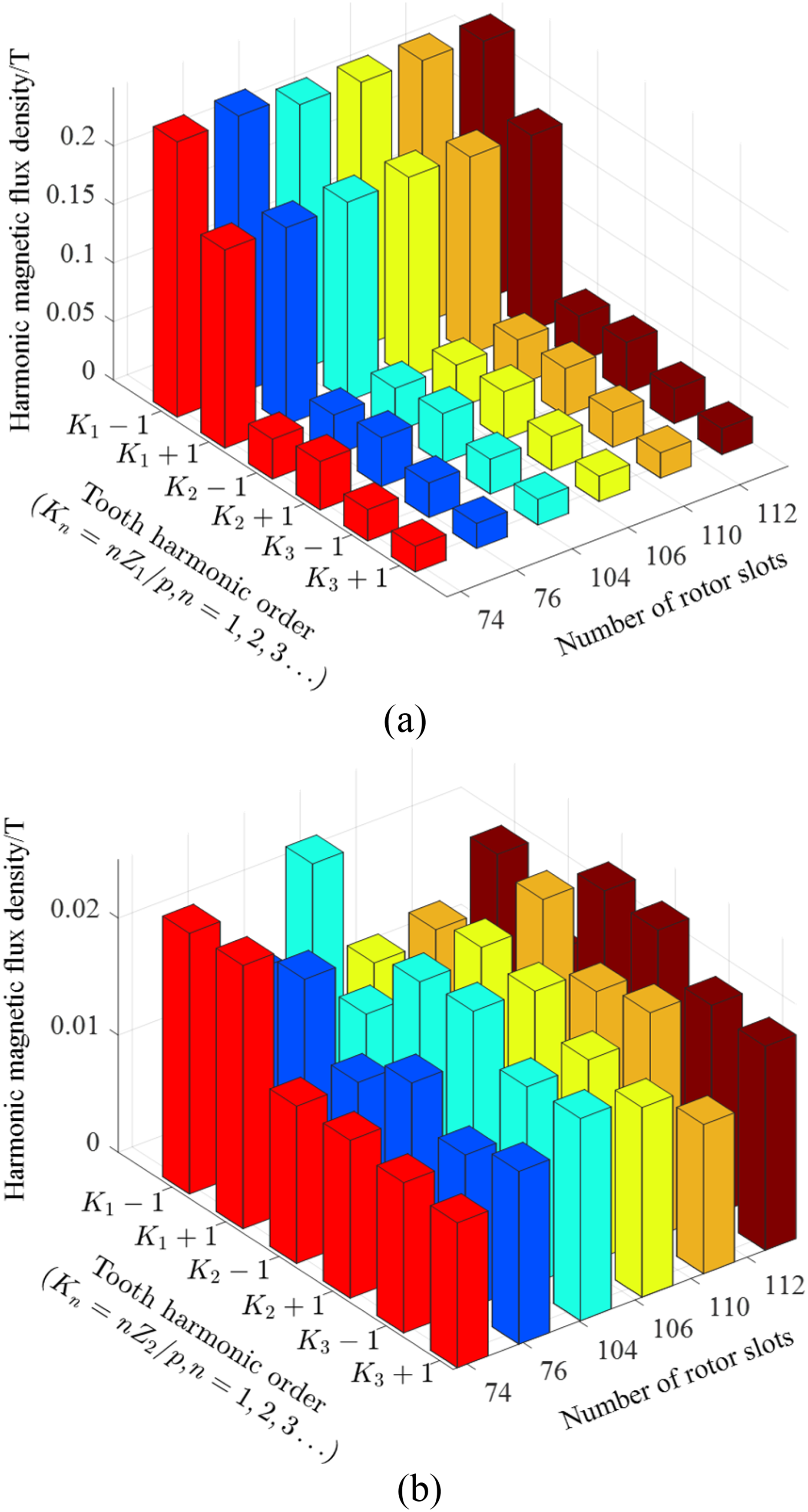
Tooth harmonic amplitude of the air-gap magnetic field under different rotor slot numbers. (a) Stator Tooth Harmonic Diagram. (b) Rotor Tooth Harmonic Diagram.
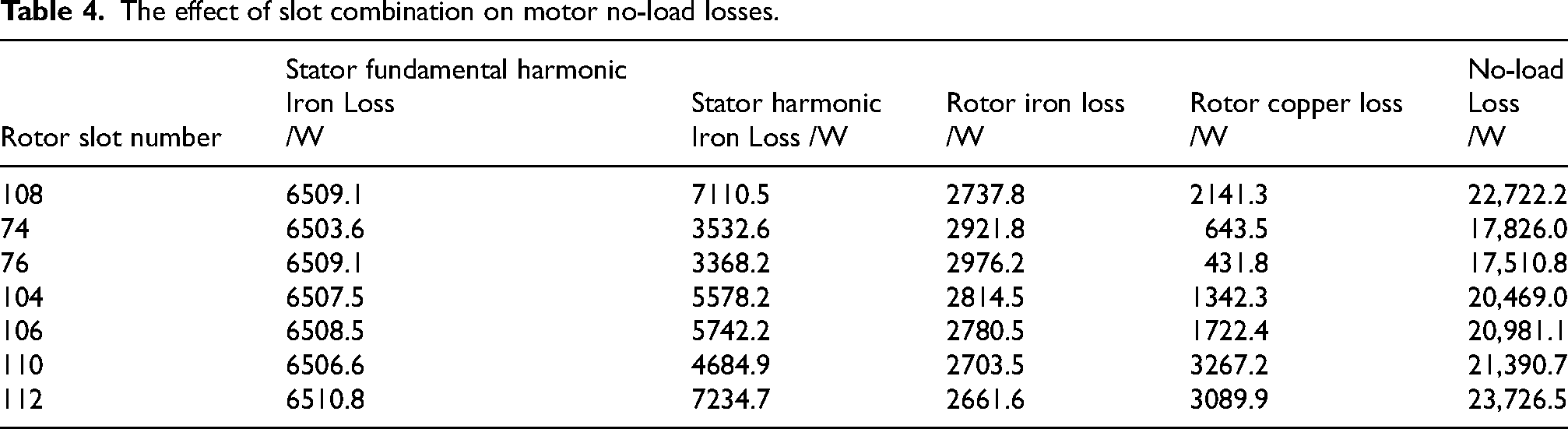
The no-load loss results for the motor with different rotor slot numbers are shown in Table 4. As analyzed in Table 4, it can be seen that when the rotor slot number is 76, the no-load loss of the motor is the lowest, at 17,510.8 W. Compared to the original design, the no-load loss of the motor is reduced by 5211.4 W. Therefore, the rotor slot number of 76 is adopted for the motor design in this paper, and the schematic diagram of the motor is shown in Figure. 11.
Motor diagram with optimized slot combination.
The effect of slot combination on motor no-load losses.
Determination of optimization variables and objectives for high-voltage multi-Poles asynchronous motor
Optimization objectives and determination of optimization variables
Considering the actual design requirements of high-voltage multi-pole machines, this paper considers the operational efficiency and material mass of the motor as optimization objectives. The optimization constraints for the motor are given by equation (10).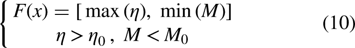
where F(x) is the multi-objective function; ƞ is the motor efficiency; M is the total mass of the motor; ƞ0 is the motor efficiency before optimization, where ƞ0 = 94.13%; M0 is the total mass of the motor before optimization, where M0 = 3136.37 kg.
The efficiency of the high-voltage multi-pole asynchronous motor can be expressed in the form of equation (11).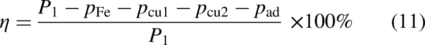
where P1 represents the input power.
The mass of the motor mainly includes the core mass of the stator and rotor, as well as the mass of the windings. The core mass of the stator and rotor is primarily related to their structure, and its mathematical model can be constructed based on structural dimension parameters, as shown in equation (12).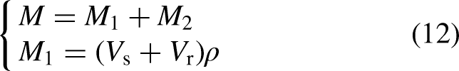
where M1 is the stator and rotor core mass; M2 is the stator winding mass; Vs is the stator core volume; Vr is the rotor core volume; ρ is the density of the silicon steel sheets.
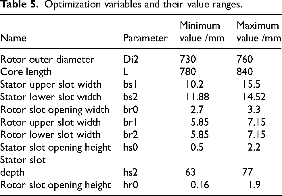
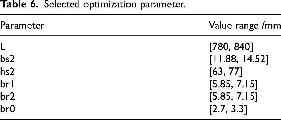
In order to fully reflect the impact of key structural parameters of the motor on its efficiency and material usage, while avoiding redundant calculations of the optimization variables, a total of 10 motor structural parameters were selected as optimization variables, as shown in Table 5.
Optimization variables and their value ranges.
Optimization variable parameterization and data collection
To ensure that each distribution range of every variable is evenly covered and to avoid samples concentrating in certain areas, this paper uses Latin hypercube sampling (LHS) 23 to randomly sample the sample space formed by the optimization variables. The sampling principle is shown in Figure. 12. The minimum discrete step length for the free variables of the motor is set to 0.01 mm. Among these, the number of rotor slots Z2 is a constrained variable, while the main dimension parameters Di2, L, and the stator and rotor slot size parameters are free variables.
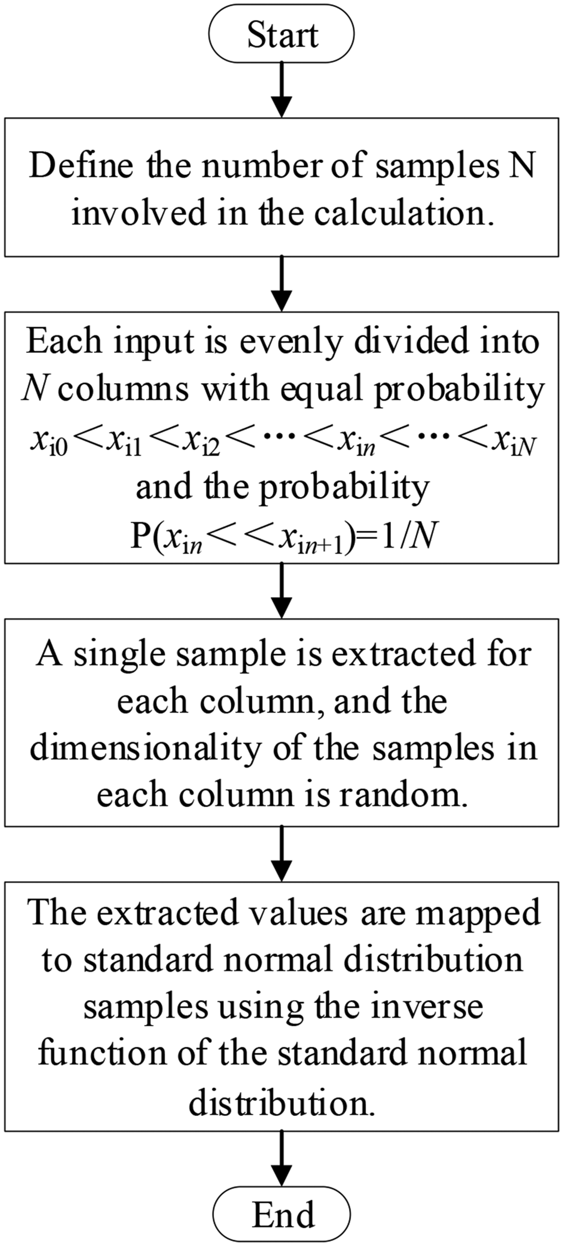
LHS schematic diagram.
Selection of motor optimization variables and genetic algorithm optimization
In order to determine the impact of optimization variables on the optimization objective and eliminate redundant optimization variables to improve the efficiency of motor optimization, this study utilizes the optiSLang optimization platform to identify critical optimization variables through sampled data analysis, thereby establishing an optimal predictive meta-model for the motor system. The mathematical model is shown in equation (13).
where COP is the coefficient of prediction; SSEPrediction is the predicted unexplained variance; SST is the total variance; N is the number of samples; yi is the sampled value; and μY is the sample mean.
Sensitivity analysis of optimization variables and filtering of redundant optimization variables
The correlation between variables is measured using the correlation coefficient ρ(X, Y). Let the correlation coefficient between two random variables X and Y be ρ(X, Y), then ρ(X, Y) is the normalized covariance between X and Y. The mathematical model is shown in equation (14).
where COV(X, Y) is the covariance between X and Y; σX is the standard deviation of X; and σY is the standard deviation of Y.
After sampling the optimization variables and optimization objectives, and constructing the optimal predictive model (as shown in equation (13)), sensitivity analysis of the optimization variables is performed using this model, generating a sensitivity correlation coefficient matrix as shown in Figure. 13. Analyzing the data in the figure, Parameters bs2, br0, br1, br2, and hs2 significantly affect the motor efficiency, while bs2, L, and hs2 exhibit notable impacts on the motor mass.
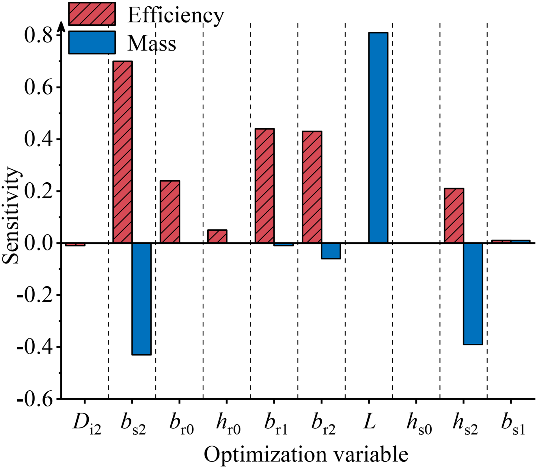
Sensitivity correlation coefficient matrix of optimization variables.
To further investigate the interaction effects of the aforementioned parameters on motor efficiency and mass, parameters with negligible impacts on optimization objectives were excluded. Sensitivity analysis was performed on bs2, br0, br1, br2, hs2, and L, with results presented in Figure. 14. As shown in Figure. 14, motor efficiency is influenced by all five parameters except L, with bs2 showing the highest impact at 48.5%. Motor mass is affected by bs2, hs2, and L, where L demonstrates the most significant influence, reaching 65.4%.
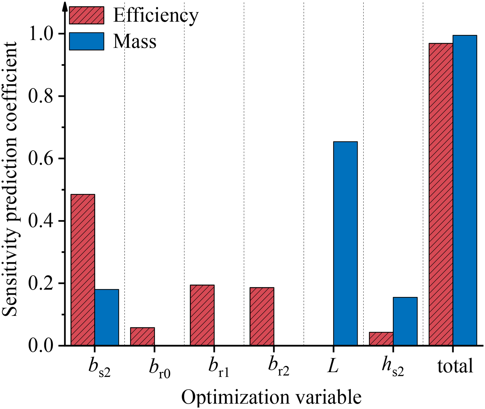
Sensitivity prediction coefficient matrix of optimization variables.
Given that parameters L and bs2 are identified as the dominant factors influencing motor mass and efficiency respectively, this section employs the optimal predictive meta-model to construct response surface plots between these two optimization variables and the corresponding objectives. The results are shown in Figure. 15.
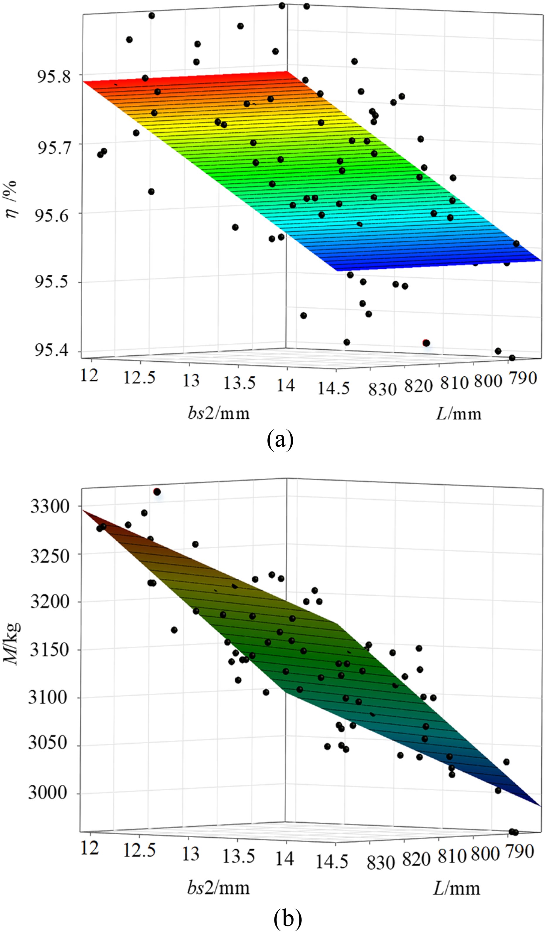
Optimization objective response surface plot. (a) Efficiency Response Surface Plot. (b) Mass Response Surface Plot.
The discrete points in the diagrams represent the values of paired optimization variables. Comparative analysis reveals that the response surface in Figure. 15(b) exhibits a steeper gradient than that in Figure. 15(a), indicating more pronounced influence of parameters bs2 and L on mass variation. Consequently, less influential variables can be systematically eliminated, reducing the number of free optimization variables from an initial set of 10 to 6 critical parameters as tabulated in Table 6.
Selected optimization parameter.
Multi-objective optimization solution and result analysis
Motor optimization requires simultaneous consideration of multiple structural variables affecting losses. Traditional methods often converge to local optima due to parameter interdependencies and high-dimensional complexity, limiting global exploration. Genetic algorithms overcome these limitations through robust global search capabilities, 24 proving effective for multi-variable optimization in complex solution spaces.
Therefore, in the optimization process, the six structural parameters are chosen as optimization variables, and the genetic algorithm is used for optimization. Additionally, when balancing the weight relationship between motor efficiency and mass, optiSLang follows the Pareto optimization principle. 25 The optimization results are presented as a Pareto 2D optimal solution set, as shown in Figure. 16 and Table 7. When the optimization prioritizes efficiency, the motor efficiency can reach up to 95.91%, an increase of 1.78% from the original, with a mass of 3055.18 kg, which is 81.19 kg lower than before. Conversely, when the optimization focuses on minimizing the effective material cost, the motor mass can be reduced to 2945.29 kg, a reduction of 191.08 kg compared to the original, while the efficiency reaches 95.64%, an improvement of 1.51%.
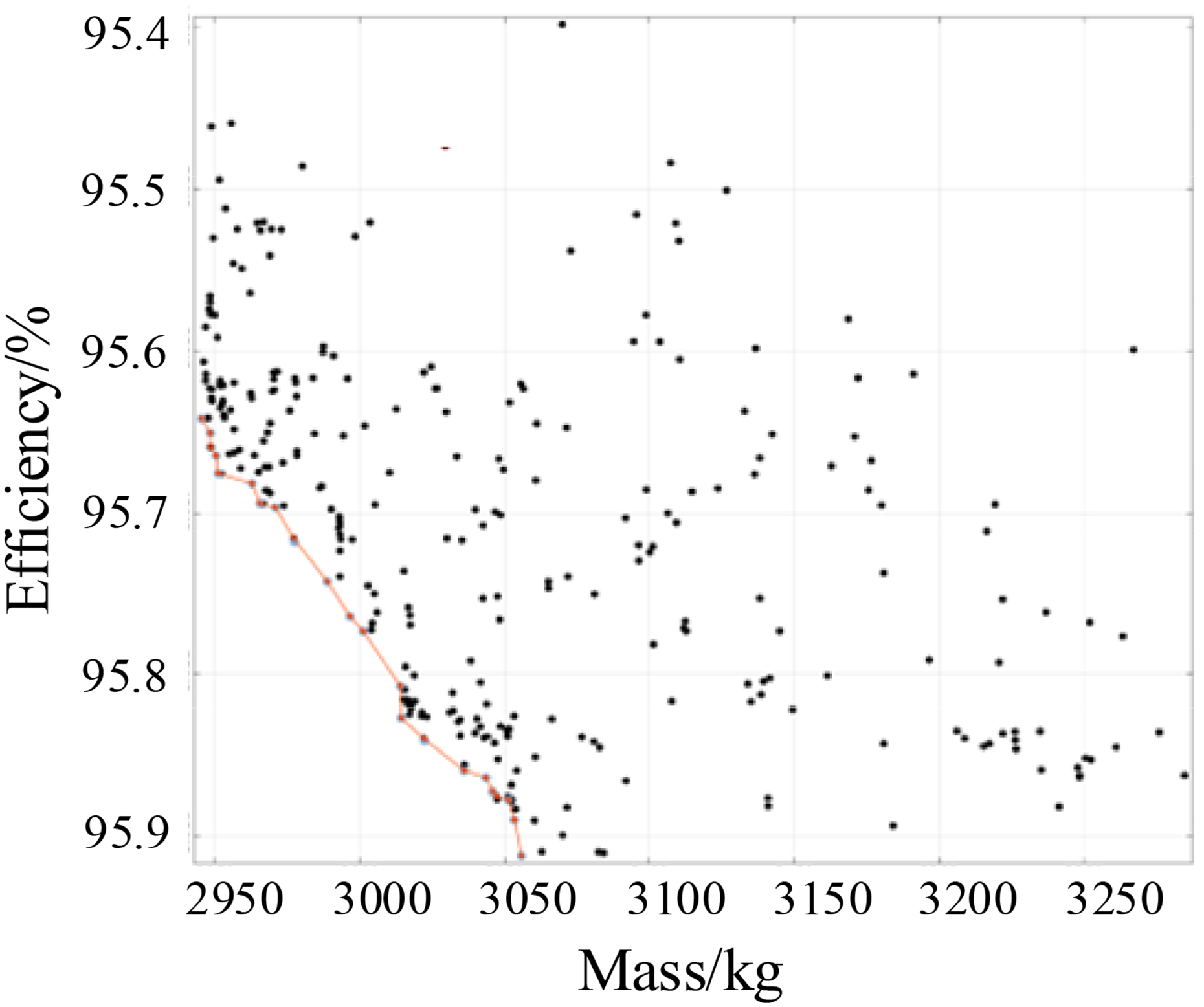
Pareto 2D optimal solution set.
Pareto optimal solution set.
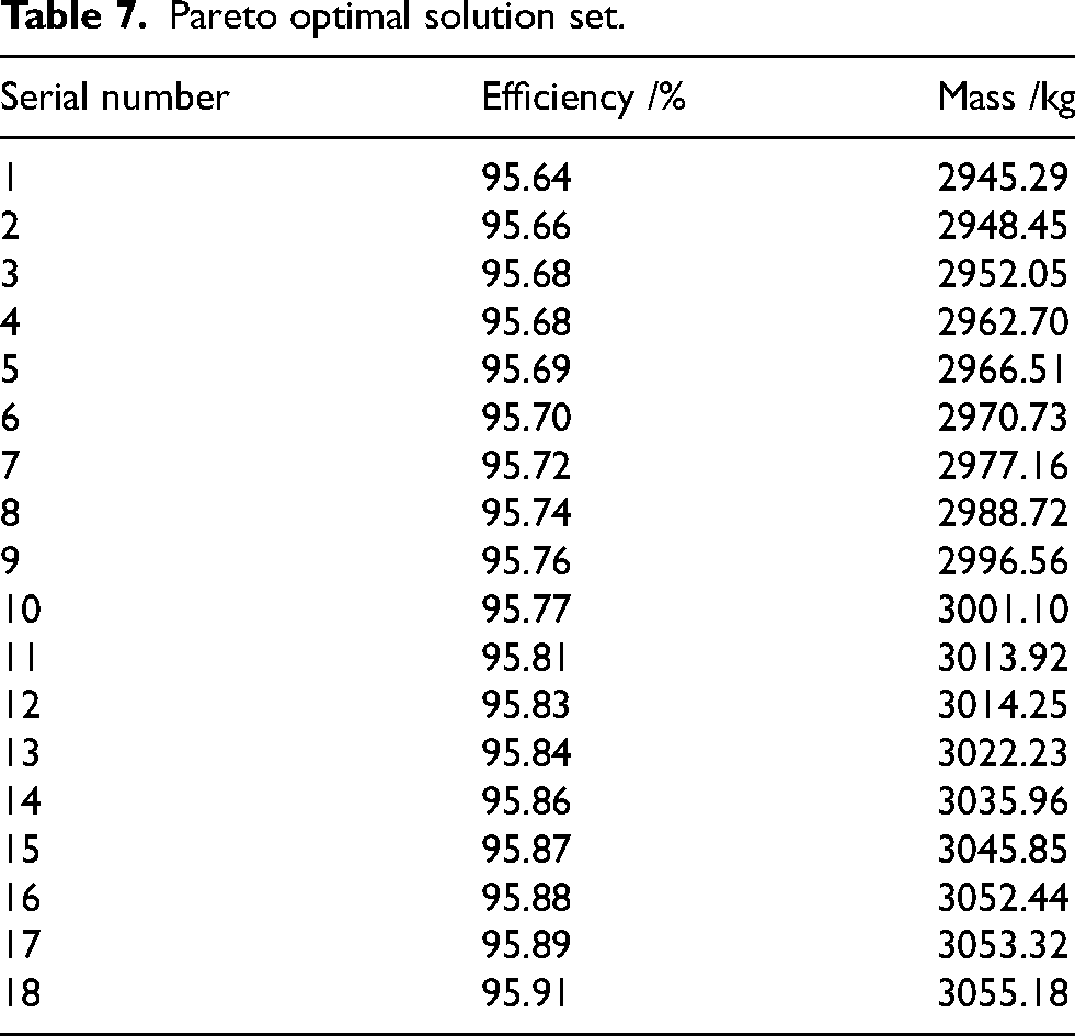
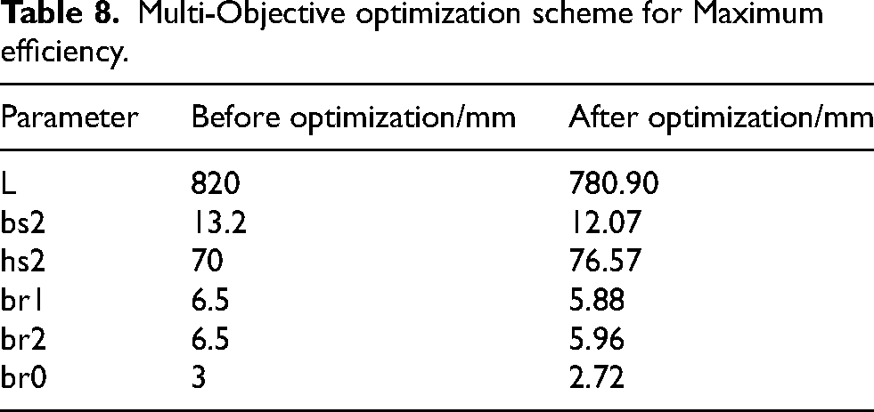
Table 8 presents the optimized solution when efficiency is maximized. Under this condition, the motor exhibits relatively better performance and effectively reduces costs. Except for the stator slot body height, the main slot parameters of the motor are reduced compared to the original design. The stator and rotor slot parameters before and after optimization are shown in Figure. 17 and 18, respectively.
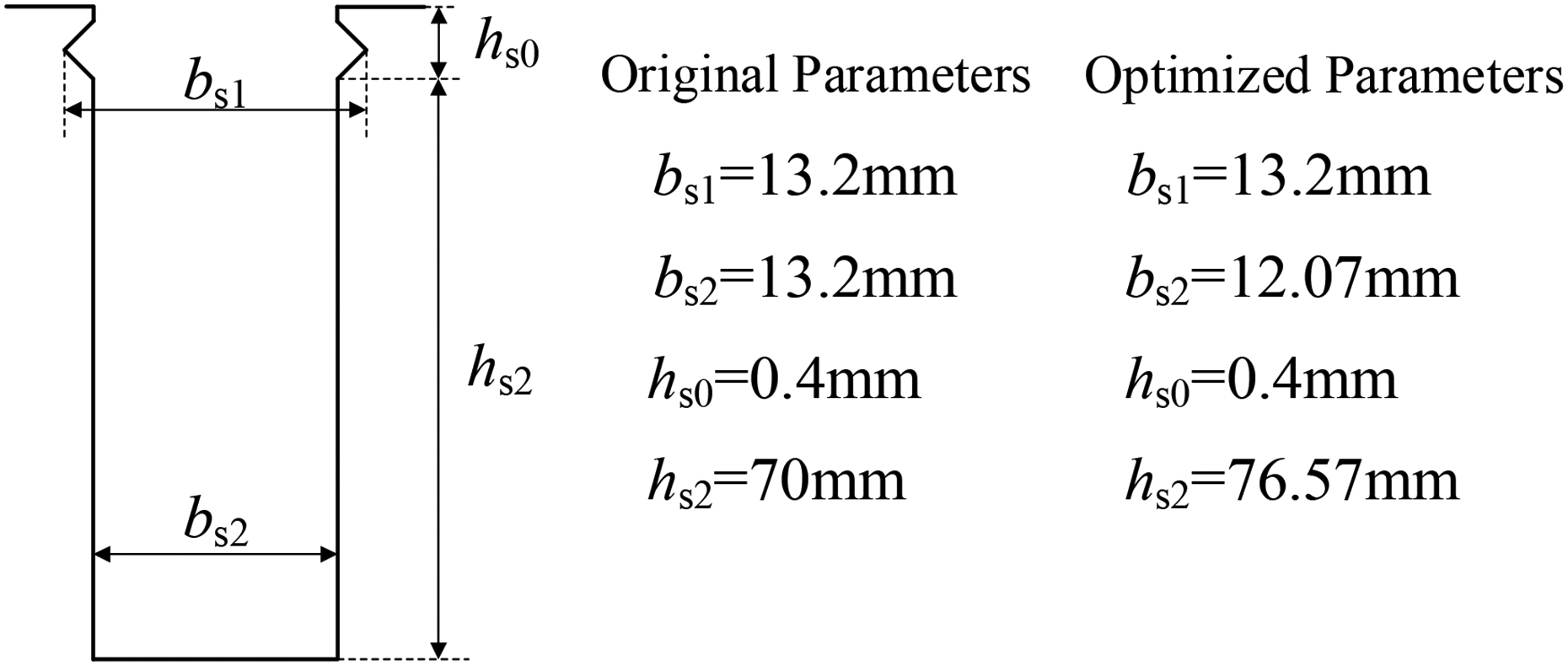
Diagram and stator slot parameters of the motor before and after optimization.
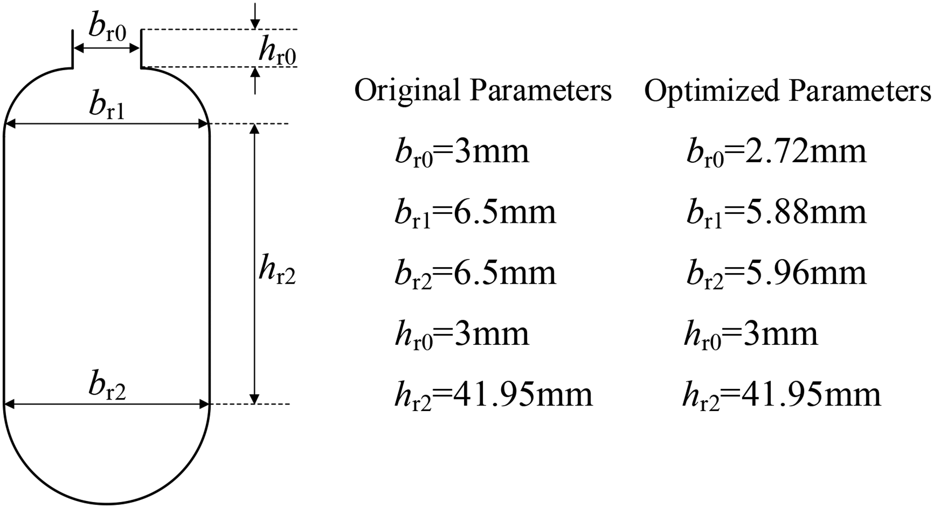
Diagram and rotor slot parameters of the motor before and after optimization.
Multi-Objective optimization scheme for Maximum efficiency.
A comparison of the air-gap flux density and harmonic content before and after optimization under optimal efficiency conditions is presented in Figure. 19. It can be observed that the fundamental wave of the air-gap magnetic flux density remains nearly unchanged after optimization, while the first- order and second-order tooth harmonics of the stator and rotor, as well as the amplitudes of nearby harmonics, show a significant reduction. Specifically: The 17th harmonic amplitude is 0.2 T, reduced by 13% compared to the original design. The 18th harmonic amplitude is 0.0011 T, reduced by 98%. The 35th harmonic amplitude is 0.057 T, reduced by 70%. The 37th harmonic amplitude is 0.054 T, reduced by 63.3%.
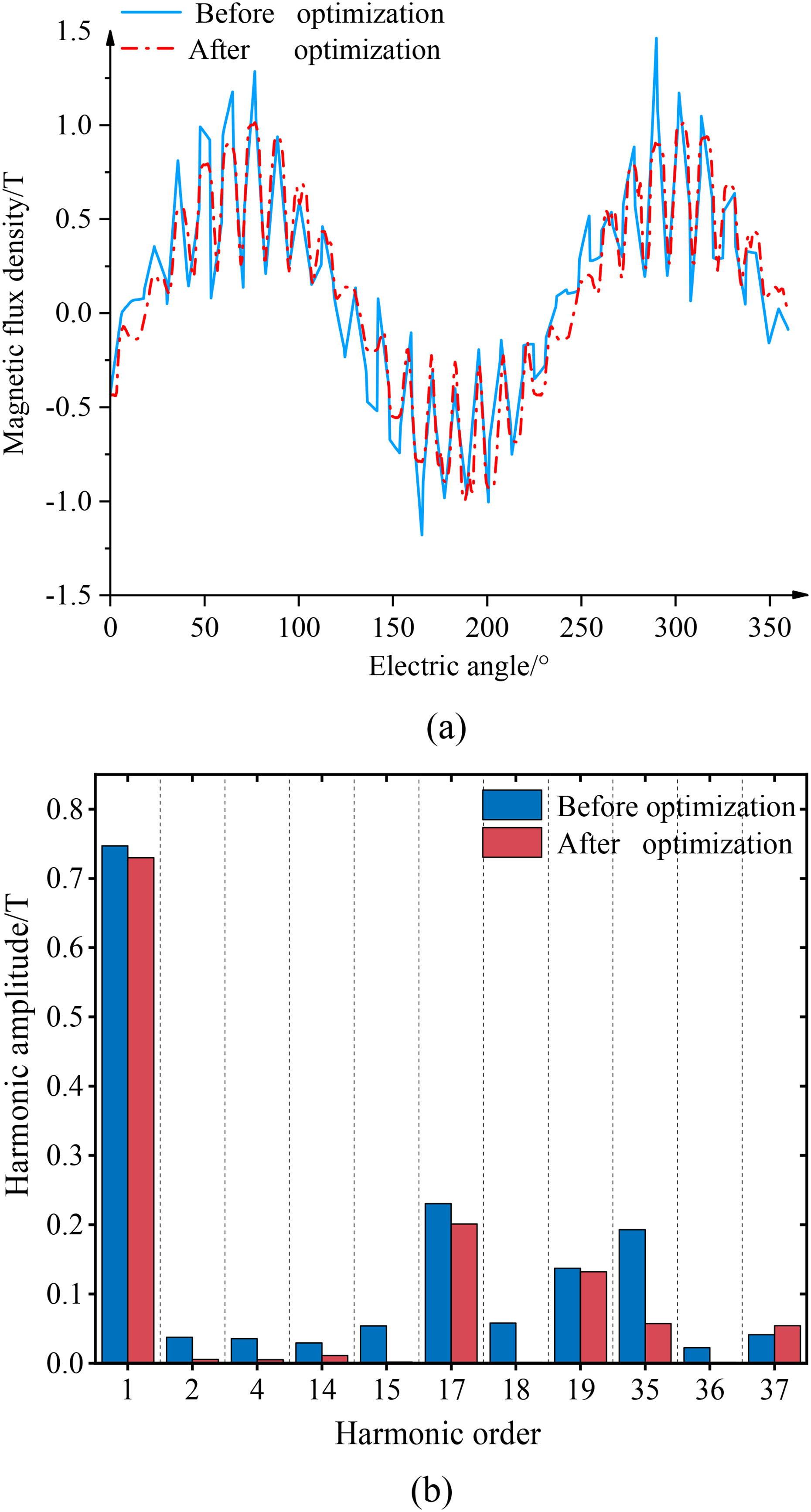
Comparison of air-gap magnetic flux density and harmonic content before and after optimization. (a) Comparison of air-gap magnetic flux density. (b) Comparison of harmonic content.
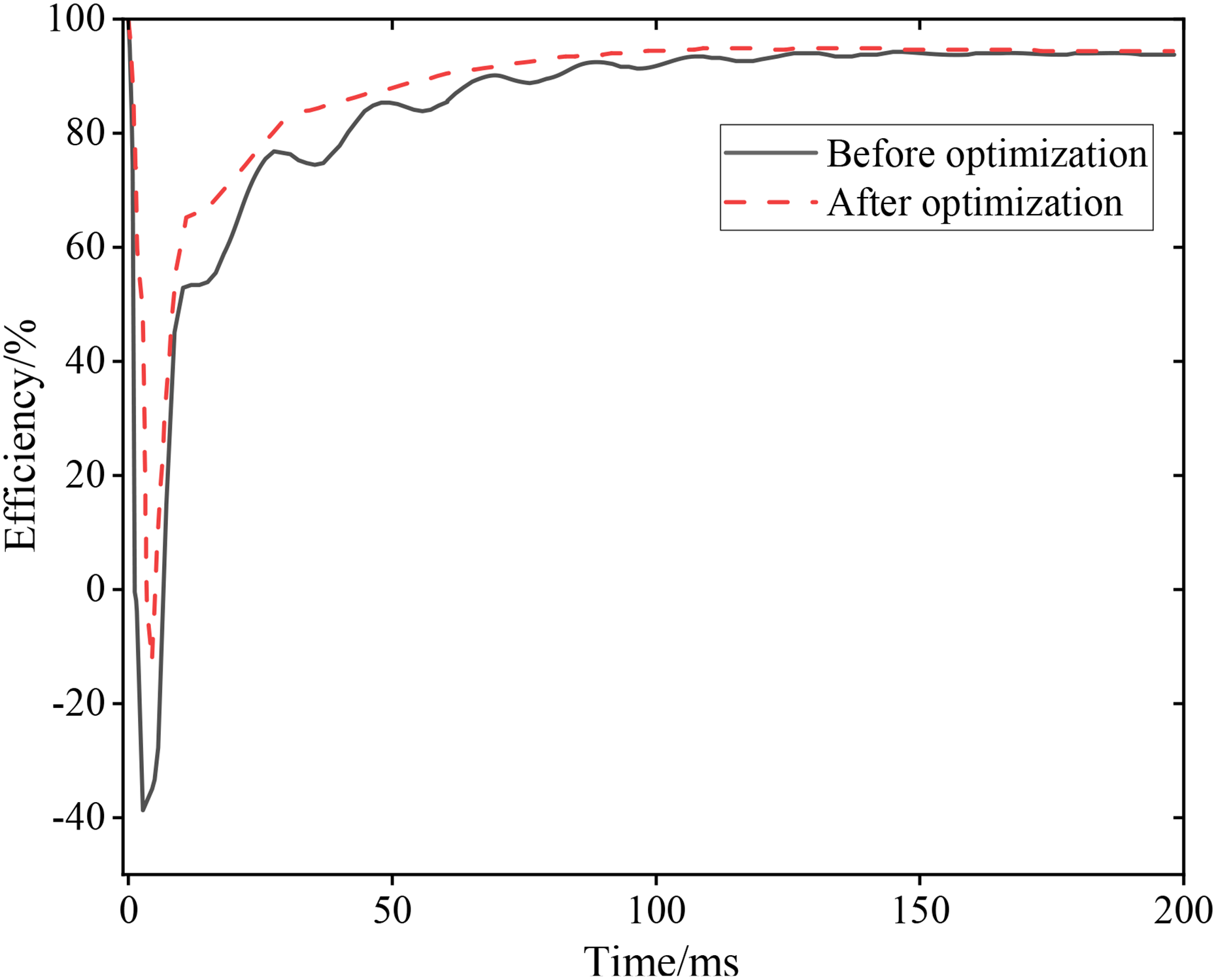
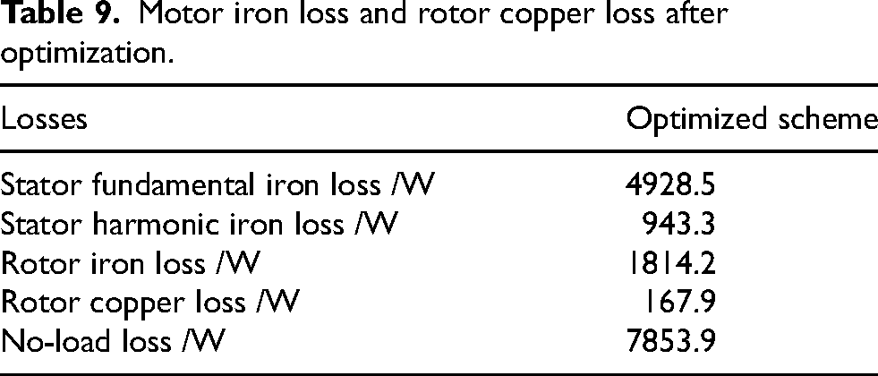
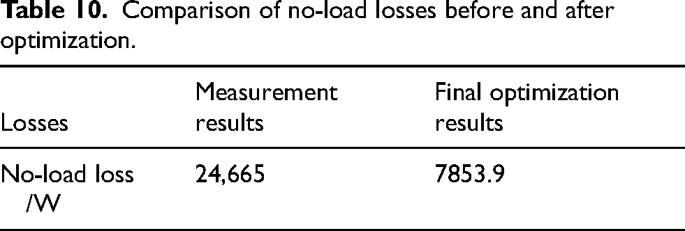
After optimization, a finite-element simulation model of the motor was established based on the optimized scheme shown in Table 8. The efficiency curve of the optimized motor was obtained and compared with that before optimization, as shown in Figure. 20. Meanwhile, the no-load loss of the motor was calculated using the no-load loss model proposed in this paper. The detailed calculation results are presented in Table 9. As shown in Figure. 20, during the same starting stage, the optimized motor achieves higher efficiency in converting electrical energy into mechanical energy. Therefore, the efficiency curve is improved in the initial starting stage compared with that before optimization. In Table 9, the stator fundamental iron loss is 4928.5 W, the stator harmonic iron loss is 943.3 W, the rotor iron loss is 1814.2 W, the rotor copper loss is 167.9 W, and the total no-load loss is 7853.9 W. Table 10 provides a comparison of the motor no-load loss before and after optimization. Analysis of the data in Table 10 shows that after optimization, the no-load loss of the motor decreased from 24,665 W to 7853.9 W, a reduction of 68.2%. The efficiency of the motor improved by 1.78%, and the material usage decreased by 81.19 kg. This verifies the effectiveness of the optimization scheme. In conclusion, an optimization design methodology integrating the optiSLang platform with a genetic algorithm is developed, which not only provides multiple optimal solutions but also enables effective enhancement of motor performance and rational control of cost-effectiveness, thereby achieving multi-objective optimization of the motor.
Comparison of motor efficiency before and after optimization.
Motor iron loss and rotor copper loss after optimization.
Comparison of no-load losses before and after optimization.
Conclusion
This study focuses on high-voltage multi-pole asynchronous motors, addressing issues such as high tooth harmonic content, which leads to low motor efficiency and severe heating. A no-load loss calculation model for high-voltage multi-pole asynchronous motors is established, and the influence of slot combination on no-load losses is quantitatively analyzed. Additionally, the optiSLang platform combined with a genetic algorithm is used to optimize the design of the motor. The following conclusions can be drawn:
The no-load loss model proposed in this paper can quantitatively calculate pFe2 and pcu2, avoiding the calculation errors caused by traditional models that categorize pFe2 and pcu2 as additional losses. The correctness of the model is validated through experimental comparison. Based on the hierarchical optimization method proposed in this paper, the no-load loss model is first used to compare different slot combination schemes. The results show that the rotor slot number significantly affects the stator harmonic iron loss and no-load rotor copper loss. For the studied motor, changing the rotor slot number from 108 to 76 reduces the stator harmonic iron loss by 3742.3 W and the no-load rotor copper loss by 1709.5 W. Then, the optiSLang platform combined with a genetic algorithm is used to optimize the continuous structural parameters of the selected slot combination scheme. The optimization process screens key variables and generates a Pareto optimal solution set. When motor efficiency is maximized, the no-load loss is reduced by 68.2%, the motor efficiency is increased by 1.78%, the material mass is decreased by 81.19 kg, and the high-order harmonic content of the air-gap magnetic flux density is reduced.
Footnotes
Funding
The authors disclosed receipt of the following financial support for the research, authorship, and/or publication of this article: This work was supported in part by the Jilin Provincial Natural Science Foundation under Grant YDZJ202301ZYTS265.
Declaration of conflicting interests
The authors declared no potential conflicts of interest with respect to the research, authorship, and/or publication of this article.
Data availability declaration
The datasets used or analysed during the current study available from the corresponding author on reasonable request.