






Abstract
Air dehumidification plays an important role in improving air quality and maintaining thermal comfort. Increasing attention is paid to the membrane-based technology, which is based on water vapour transmembrane transport driven by mass transfer potential, together with sensible heat transfer under temperature difference. Membrane-based air dehumidification has been applied in heating, ventilation and air conditioning, compressed air dehumidification and environmental control in space vehicle, and some other engineering fields. This paper summarizes recent research results in these fields, including fundamental principles, membrane materials, membrane module structures, operation conditions and theory models. In the end, two methods of membrane-based dehumidification performance evaluation are introduced from perspective of energy and exergy, respectively.
Introduction
Humidity is an important parameter that can affect thermal comfort. 1 High humidity will not only lead to discomfort and influence the body surface temperature, but also benefit germs breeding, which gives rise to many health problems such as SARS and H1N1.2,3 The ASHRAE Standard 62-2001 recommends the relative humidity of 30–60% for indoor environment. 4 In some special circumstances such as machine room, museum and library, high humidity needs to be avoided.
In some hot and humid regions such as Southern China where outside air humidity stays above 80–90% continuously for a dozen of days, 5 latent heat load caused by fresh ventilation air of high humidity can account for 20–40% of the total energy consumption of heating, ventilation and air conditioning (HVAC) system. 3 Obviously, effective dehumidification for fresh air would be of great importance in energy saving and reduction of carbon emission. It is shown that building energy consumption could be reduced by 20–64% by using efficient dehumidification technologies. 6
As can be seen, air dehumidification can play more and more important role in energy saving. Considering dehumidification efficiency and special applications for further, membrane-based dehumidification stands out from various dehumidification technologies, for its simple structure without rotary parts, non-direct contacting of air with working substance, continuously working mode, reliability, high dehumidification efficiency and so on.7,8 Due to these advantages, membrane-based air dehumidification is being studied extensively and even being taken into practical applications, including total heat recovery in HVAC, 9 compressed air dehumidification, 10 space application, 11 etc.
Membrane-based dehumidification in field of HVAC
In air conditioning, fresh air is usually ventilated into room to guarantee indoor air quality (IAQ). However, as mentioned above, high humidity of fresh air not only brings discomfort, but also adds heat load to HVAC system. Dehumidification for fresh air before cooling is thereby necessary. Traditional dehumidification technology consumes much energy, such as heat-driven dehumidification by desiccant and common dew point dehumidification. On the other hand, additional parts designed for dehumidification also add the complexity of system as well. However, liquid desiccant and dew point methods have some limitations, especially the fouling and hygiene problems. Therefore, membrane method is proposed as a new type of dehumidification technology. In the novel HVAC system, fresh air is cooled by chilled ceiling 12 or by evaporator of compression refrigeration system,13,14 after exchanging the total heat with exhaust air13,14 or liquid desiccant.15,16 There are abundant investigations on membrane-based dehumidification applied in HVAC, with topics from fundamental principles, materials, structures and operation conditions to theory models. Zhang summarized the work of his team over the past 10 years covering almost all aspects of total heat recovery with membranes applied in HVAC from fundamentals to engineering applications. 17 Combining a refrigeration fresh air unit with the developed membrane-based total heat exchanger, the novel system obtained a COP as high as 5.8. Compared with this, the COPs of the traditional common systems were usually below 2.8.
Fundamental principles
Membrane-based dehumidification is based on moisture transfer driven by mass transfer potential difference between membrane’s two sides called feed side and permeate side, respectively. In HVAC system, the mass transfer potential mainly comes from water vapour partial pressure difference (also humidity ratio difference). Mass transfer flux, J (kg s−1) is defined by equation (1):
The relative humidity of air is calculated by humidity ratio and temperature by equation (2),
18
as
In particular, since a saturated thin layer exists on the surface of water, the humidity ratio of water can be formulated in the humidity ratio of saturated humid air:
9
Similarly, the humidity ratio of solution can be calculated by
Materials
Selectivity and permeability are two significant performance characteristics of material used for membrane-based air dehumidification. Selectivity means that only vapour can transfer through membrane while air is obstructed outside, consequently realizing separation. However, absolute separation is impossible, since air can also get through membrane pores to some extent, although the proportion is very small versus vapour. For this reason, porous hydrophilic membrane is usually applied to air dehumidification, such as polyvinyl alcohol (PVA), celluloid, cellulose acetate (CA) and polyimide (PI). 19 Generally speaking, the higher the porosity of membrane is, the faster the vapour transfers and therefore the higher the permeability will be. In addition, hydrophilicity of membrane material also benefits vapour permeation, which may be more influential in some degree.
Water vapour permeabilities and H2O/N2 selectivities at 30℃ for various organic polymers. 20
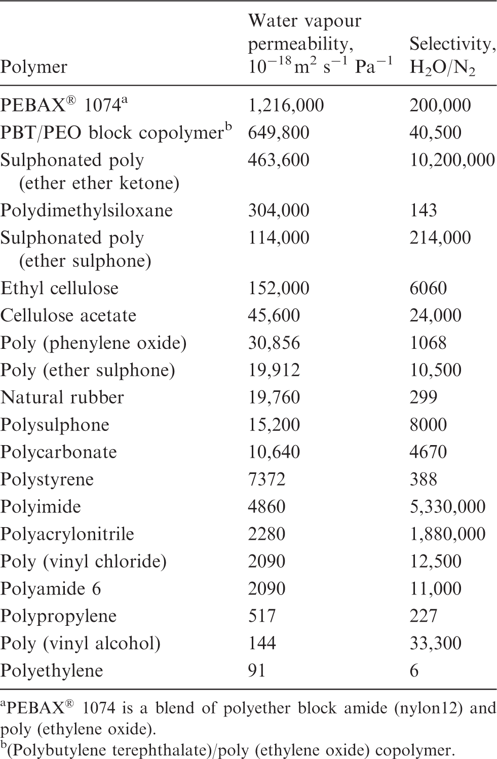
PEBAX® 1074 is a blend of polyether block amide (nylon12) and poly (ethylene oxide).
(Polybutylene terephthalate)/poly (ethylene oxide) copolymer.
As shown in Table 1, there are very few membranes combining high water vapour permeability with high H2O/N2 selectivity, such as PEBAX® 1074 and sulphonated poly (ether ether ketone). For most membranes, unfortunately, high water vapour permeability and high H2O/N2 selectivity cannot be obtained at the same time. For instance, PI and polyacrylonitrile have extremely high H2O/N2 selectivities of 5,330,000 and 1,880,000, respectively, with quite low water vapour permeabilities of 4.86 × 10⁻¹⁵ m2 s−1 Pa−1 and 2.28 × 10⁻¹⁵ m2 s−1 Pa−1, respectively . Moreover, for some other membranes such as polypropylene and polyethylene, both permeability and selectivity are very low.
Permeability and selectivity are incompatible with each other for most membranes of simple structure and property. Therefore, membrane module is usually fabricated with composite membranes, or taken modification technology. Sometimes the two technologies are utilized together. To fabricate composite membrane, an active layer is sedimentated as a skin layer on the surface of a support layer. The high hydrophilic skin layer made from dense membrane or liquid membrane has a greater mass transfer resistance and is therefore manufactured thinner than the support layer which primarily contributes to enhancement on mechanical strength.
A green method of one-step fabrication of an asymmetric CA membrane was introduced in the literature. 21 CA, acetic acid and de-ionized water of specific weight ratios were prepared. After some treatment of mixing, cooling, slicing, immersing in tap water twice and then drying in vacuum oven, an asymmetric membrane with a dense layer on the surface was formed. It was found that the surface was denser with an increase of de-ionized water in the casting solution.
The mass transfer performance of an asymmetric membrane was studied. 22 The thickness of the dense layer accounted for only 1/10 of the total thickness, while mass transfer resistance accounted for more than 50%. The remaining resistance of less than 50% was equally accounted for by convective mass transfer resistance of the boundary layers of both sides and diffusion resistance of the support layer. It was shown that asymmetric membrane had better moisture transfer capacity with respect to traditional paper membrane.
Porous structure conduces to moisture permeation, but plain porous membrane usually cannot be directly applied to dehumidification yet for its relatively low vapour permeability, in the order of 10−12–10−13 m2 s−1 (it should be noted that the driven force of permeation here is considered as humidity difference, hence the unit of vapour permeability is m2 s−1), compared with 10−9 m2 s−1 of liquid membrane. 23 Considering this, simple structured membrane is usually modified by depositing hydrophilic material such as quaternary ammonium salt or halide salt into membrane pores.
An LiCl solution-based composite supported liquid membrane (CSLM) was successfully fabricated. 24 The liquid LiCl solution was immobilized into the macro and micro pores of porous support CA membrane, while two hydrophilic polyvinylidene fluoride (PVDF) membranes were formed on both surfaces as skin layers. It was observed that the moisture permeation rate through the CSLM was two times higher than that through the solid membrane.
Silicate membrane Al-MCM-48 was studied on H2O/O2 separation process to compare with MCM-48.
25
The α-Al membrane was used as support with pore diameter of 0.2 µm and thickness of 2 mm. The thickness of skin layer was 25 µm and 45 µm for MCM-48 and Al-MCM-48, respectively, as shown in Figure 1. Since the addition of aluminium has promoted dissolution of polar water molecule, Al-MCM-48 would provide better hydrophilicity.
SEM micrograph of (a) MCM-48 membrane and (b) Al-MCM-48 membrane.
25

PVA solution was blended with LiCl to fabricate dense membrane, while porous polythersulphone was used as support. 26 The composite membrane had a smaller contact angle when immersed in water, gaining better hydrophilicity; as a consequence the moisture permeation got facilitated. In addition, the membrane became more flexible and mechanically robust due to a decrease in crystallinity.
Liquid may immerse in pores and destroy inner structure when contacting membrane directly, so it is necessary to apply hydrophobization on the permeate side, or composite with a layer of hydrophobic membrane. This would benefit moisture removal, thus preventing concentration polarization. PVDF is a typical hydrophobic material applied to dehumidification, on which some hydrophilic materials such as PVA and polyethylene glycol are usually modified to form a hydrophilic–hydrophobic composite membrane.27–30
A PVDF membrane was modified with a dense layer made from
What has been discussed above is mainly on the separation of water vapour from oxygen or nitrogen, and surely it is a preliminary demand for dehumidification anyhow. However, besides moisture and the major components of air, volatile organic compounds (VOCs) may enter the fresh air from the exhaust air through membrane pores as well. For the sake of IAQ, membrane material should be a great barrier to VOCs. 32 From the comprehensive perspective, PVA-1 (PVA with LiCl as an additive) is the best material with a high moisture permeability of 3.7 × 10⁻⁸ m2 s−1 and a high water vapour selectivity with respect to VOCs (360, 333, 340, 451 and 333 for acetic acid, formaldehyde, acetaldehyde, toluene and ethane, respectively). 33 As for airborne bacterial, Ag+ is alternative for its sterilization ability, which can be coated on the membrane surface. 34
Structures
Similar to conventional sensible heat exchanger, there are mainly two forms for membrane module, shell-and-tube type35–37 and plate type.38,39
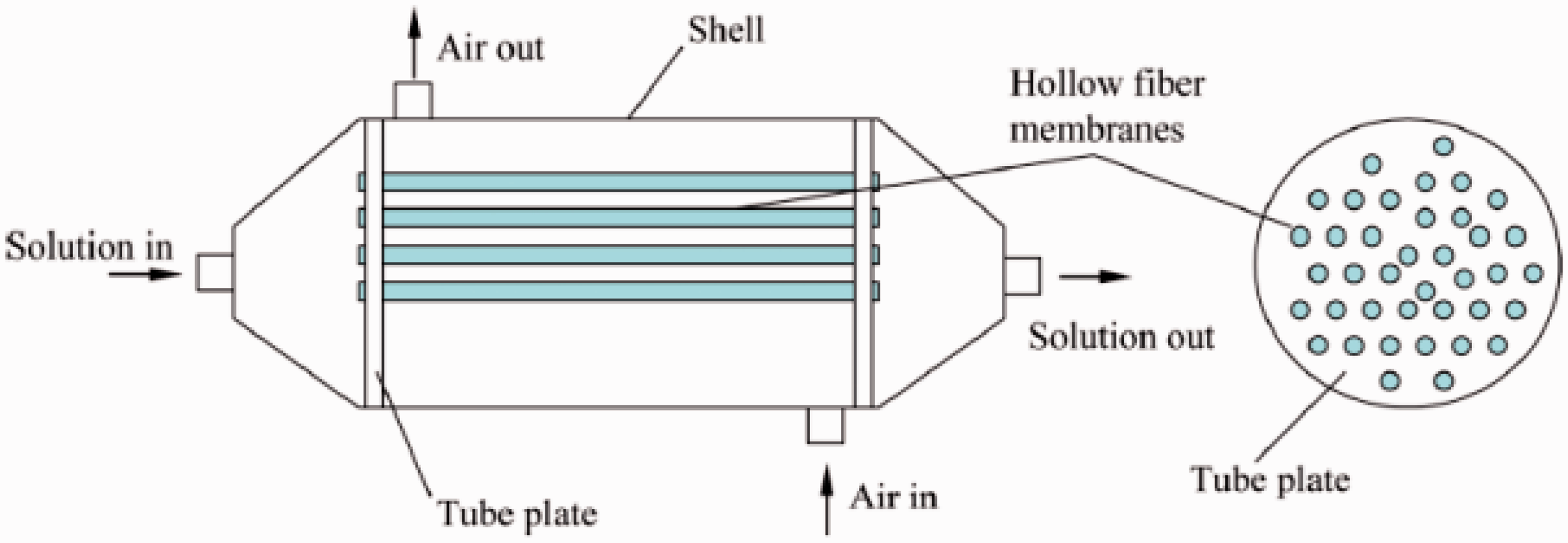
Shell-and-tube membrane module is fabricated with a bundle of hollow fibres packed inside shell, obtaining very excellent specific area even as high as 2000 m2 m−3. Feed air flows at the tube side, or shell side. Figure 2 shows a type of counter flow hollow fibre membrane dehumidifier, with feed air flowing at the shell side and LiCl at the tube side, whose packing fraction is 0.25, and specific area is 750 m2 m−3.
40
A type of hollow fibre membrane module.
40
With the same structure as conventional metal shell-and-tube heat exchanger, hollow fibre membrane module exhibits extremely different features, however, including much smaller characteristic diameters and much larger number of fibres. As a result, the flow tends to be turbulent even at much lower Reynolds numbers. The κ–ω model was found to fit the experiments well where Re ranged from 100 to 300, while the laminar model only fitted the tests well at Re below 150. 41 In addition, packing density is a dominant factor for performance in membrane module, while the impact of flow arrangement is quite little. In contrary to this, flow arrangement plays an important role in sensible heat exchanger. 42
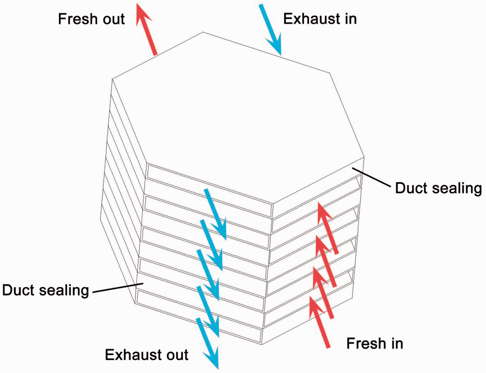
Flat plate is another common type due to its simple structure. Feed air and permeate fluid flow staggeredly between adjacent plates. Figure 3 presents the structure of a quasi-counter membrane dehumidifier.
43
The flat-plate total heat exchanger exhibits quite different heat transfer performances from the traditional ones. Due to the combination of heat and mass transfer, it was found that the Nusselt numbers calculated by real boundary condition deviated largely from those by uniform wall temperature condition and uniform wall heat flux condition under low aspect ratios.
44
A type of quasi-counter plate membrane module.
43
Besides flat-plate type, membrane module can be made in the form of plate-fin type as well. As a result of lower fin conductance parameter (a dimensionless number representing the heat conductivity of the fins with respect to that of the fluid), the heat transfer performances in plate-fin membrane exchanger indicate a great difference from those in conventional metal-fin sensible heat exchanger. 45 In metal-fin ducts, both plates and fins contribute to the heat transfer to/from the fluid, while the heat is mainly transferred through the plates in polymer-fin ducts, leading to a slower heat exchange between the plates and the bulk fluid and obtaining lower fin efficiencies and Nusselt numbers therefore.46,47
A novel membrane module was proposed which used CSLMs as transfer plates with addition of paper membrane fins. The latent efficiency of the novel module was 60% higher than the total paper membrane module. 48
Just like the traditional sensible heat exchanger, the basic flow configuration of membrane module includes current, counter and cross flows. The actual membrane module may combine current with cross or counter with cross. In the counter flow, two headers would need to be placed side by side at the inlet and outlet, while the counter–cross flow configuration avoids such header complexity by placing the inlet and outlet headers of the two fluids on the top and bottom of the module. 6 It was predicted 49 that a small entrance ratio (ratio of liquid entrance length to exchanger length) and exchanger aspect ratio (ratio of membrane height to exchanger length) of the counter–cross flow could always result in a better performance than the cross flow with the same membrane surface area.
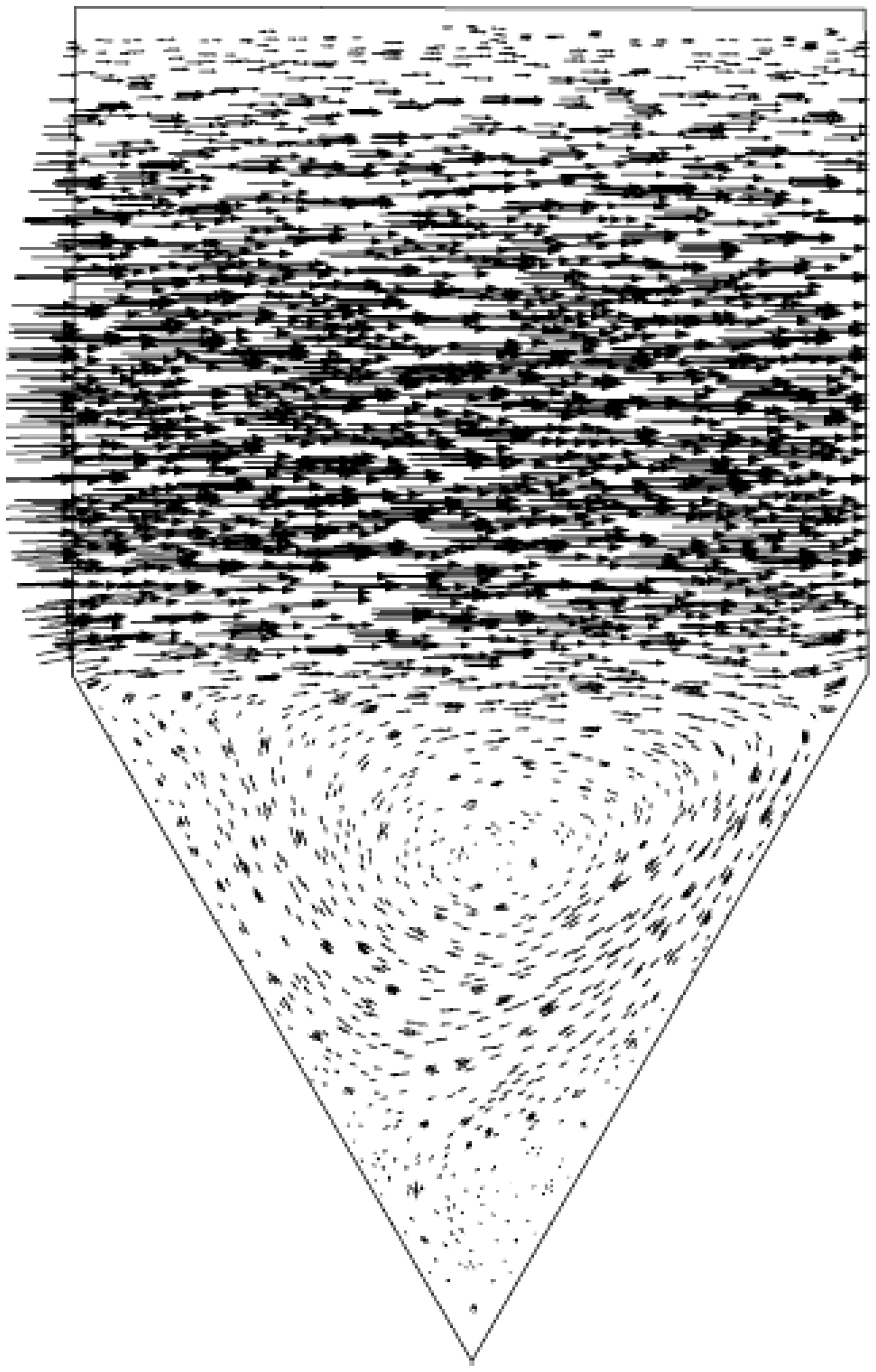
Combining cross-flow configuration with triangular ducts, the cross-corrugated structure provides high mass transfer capacities, due to the strong swirls generated in the lower troughs that intensify the momentum and mass transfer, as shown in Figure 4.50,51 It was observed that the corrugation angle of 90° could obtain the greatest mass transfer improvement compared with 0° and 45°.
52
As a result of the complex duct structure, conventional laminar correlations could not predict the flow with low Reynolds number any more. Low Reynolds number κ–ω model was validated to fit the experiment results well in the Re range of 100–3000
50
and 500–5000,
53
respectively, for different duct sizes. A wider transitional flow range of Re at 100–6000 was studied using low Reynolds number κ–ω model as well.
54
As for turbulent flow (2000 < Re < 20,000), Reynolds stress model gave the best prediction.
55
Velocity vectors in cross-corrugated duct at Re = 1500.
50
Recently, the flow maldistribution problem has drawn much attention, which universally exists for various structures and brings significant performance deterioration. It may be caused by the complex structures such as irregular fibre packing, non-uniform arrangement, large channel pitch and tortuous inlet header.56–60 Generally, there exists more serious flow maldistribution for the flat-plate structure compared to the plate-fin structure.
Operation conditions
During dehumidification process, water vapour from fresh air permeates through membrane pores and reaches the other side. Water molecules accumulate in the surface pores of the permeate side, restrained by capillary force, leading to a decrease in mass transfer potential. So there is a need to build in some mechanism to remove effectively to get a better performance. In HVAC system, indoor exhaust air usually performs as working fluid of the permeate side.
A hollow fibre membrane module was tested in an air-conditioned room.
37
Room air was first humidified and heated in a hot/cool water bath, then exchanged heat and moisture with the exhaust air flow directly driven from room, as shown in Figure 5. Various inlet conditions of mass flow rate, temperature and humidity were tested to observe the effects on dehumidification performance.
An experimental setup for membrane module heat and moisture recovery.
37

In addition to low humidity air, liquid is also usually used as dehumidification fluid. Owing to the high absorption capacity per unit mass of liquid phase, very low liquid velocity can be adopted, resulting in low pressure loss along the membrane module. 61
Different from air-to-air mode in which the air of the permeate side is exhausted, air-to-solution mode adopts a circulation loop for the solution. As dehumidification is processing, the solution temperature increases, and concentration drops, subsequently the mass transfer potential decreases. Considering that the exhaust air is relatively hot and dry compared with the diluted solution, another membrane module can be used to recover the sensible and latent heat of solution to keep the dehumidification proceeding,6,8 as shown in Figure 6.
Schematic of a run-around membrane energy exchanger system in HVAC line.
6

A hollow fibre membrane module was experimentally investigated using a saturated LiCl solution flowing in tubes, with air flowing in shell by cross flow. 62 Experimental results indicated that the mass flow rate of LiCl solution affected dehumidification effectiveness little, while an increase in air flow rate brought about a slight decrease in effectiveness.
Benefiting from the high absorption capacity, liquid desiccant is commonly applied to membrane total heat exchanger in vapour compression refrigeration and dehumidification hybrid system. In the hybrid system, the liquid desiccant is initially cooled by evaporator, and then it takes away the sensible and latent heat of fresh air simultaneously through the membrane exchanger. The diluted desiccant is regenerated by the combination of condenser and another membrane exchanger to maintain the absorption capacity.15,16
Theoretically, as long as the permeate side can offer a relatively low water vapour partial pressure atmosphere, dehumidification would be possible. Cooled pure water is thus an alternative working fluid for the permeate side, especially for its non-corrosivity and low price relative to solution. 8
Theory models
During membrane-based dehumidification process, heat and mass transfer proceed simultaneously. Heat is transferred by conductivity across membrane and convection of fluid, forming linear temperature distribution across membrane and temperature boundary layers on the surfaces.63,64 The humidity distribution is similar, as shown in Figure 7.
Distribution of temperature and humidity inside the membrane and on the surfaces.
Diffusion in membrane
Seshadri and Lin
25
identified transfer mechanism of gas in membrane as activated diffusion, Knudsen diffusion and viscous flow, dominating in microporous (dp < 2 nm), mesoporous (2 nm < dp < 50 nm) and macroporous (dp > 50 nm) membrane, successively. Theoretically, the best separation factor can be gained when Knudsen diffusion is the governing mechanism as represented by equation (5). In this mechanism, permeability is inversely proportional to square roots of the molecule weight
Zhang
23
considered the transfer mechanism in most microporous membrane as combination of Knudsen and molecule diffusion.
23
The molecular diffusivity of water vapour in air is given by equation (6)
Another diffusion mechanism in dense membrane is capillary condensation. Under this mechanism, water vapour is absorbed by membrane surface, then condensates in membrane pores at a relatively lower pressure and blocks the flow of air consequently, resulting in higher selectivity than Knudsen diffusion. 25 The latent heat released by water vapour condensation transfers towards the other side under the temperature difference, conferring the system the evaporation energy while water leaves the membrane pores at vapour state. 32 To establish mathematical models easily, this process is sometimes simplified so that no phase change occurs in air-to-air mode 37 and only condensation occurs at the liquid–membrane interface in air-to-liquid mode. 62
Convective transfer in boundary layers
The same heat transfer correlation can be used for flow both between plates and in tube. For laminar flow, Hausen is commonly used to calculate the Nusselt number
65
as represented by equation (8)
When
For the shell side of hollow fibre membrane, if fluid flows along axis of tube, the Nusselt number can be obtained by correlation for flow in tube, with hydrodynamic diameter calculated by flow area and wet perimeter of the shell side. If fluid flows perpendicularly to tube, Zukauskas is used
66
Many literature works give the similar form of mass transfer correlation of the shell side as equation (12) as follows67–70
The Sherwood number of flow between plates or in tube that can be calculated by Chilton–Colburn analogy
37
is represented by equation (17) as
The correlation below can also be used to calculate the Sherwood number of flow in tube by equation (18)
71
Convective heat and mass transfer coefficients in boundary layers are calculated by equations (19) and (20) as follows:
Then the total heat and mass transfer can be obtained by equations (21) and (22):
Since the diffusion flux in membrane is equal to the overall transmembrane transfer flux, the isothermal sorption curve of membrane can be used to calculate the transfer flux instead of resolving the convective mass transfer coefficient.72,73 The isothermal sorption curve can be obtained by humidification experiment
Solution
The solution to heat and mass transfer process is obtained by numerical approach. By establishing mass, momentum, energy and component governing equations, various parameters including temperature, humidity and velocity can be solved simultaneously. Usually it is simplified that (1) the process is one-dimensional; (2) both of the two flows are uniform; (3) mass change in either flow caused by moisture transfer can be neglected and (4) heat and mass diffusion along axial direction are negligible. By simplification, mass and momentum equations can be omitted, leaving only energy and component equations to solve.
As sometimes more details are preferred, completed governing equations need to be established.
76
A free surface model approach was used to investigate the three-dimensional heat and mass transfer process in a hollow fibre membrane module.
77
In the fibre cell, liquid flowed in tube, while air flowed in annular channel surrounded by outer wall of tube and the free surface, as shown in Figure 8. Entry section effect was observed, with quite high values of Nusselt number and Sherwood number in entry regions. In addition, with momentum equation solved together, the velocity field was also obtained.
The fibre cell with a free surface.
77

As mentioned fragmentarily above, the transport data in membrane module display a tremendous difference from that in sensible heat exchanger, as a result of the special structures and the conjugate heat and mass transfer boundary conditions. Especially for the flow regime classification according to Reynolds number, the turbulent flow occurs at much lower Reynolds number compared with classical data. On the other hand, either uniform wall temperature or uniform wall heat flux boundary condition only applies to some specific situations of packing density and mass flow.78,79 Some numerical methods such as low Reynolds number κ–ω model and Reynolds stress model have been successfully adopted to predict the combined heat and mass transfer process in membrane module.
Compressed air dehumidification
Materials, structures and operation conditions
Compressed air dehumidification is another common application of membrane-based dehumidification due to less energy consumption and lower operation cost. Quite different from dehumidification under ambient pressure, compressed air dehumidification is driven by much larger water vapour pressure difference, so the membrane module has to be fabricated as the shell-and-tube form that can sustain high pressure.
Figure 9 presents the linear regression lines of water vapour flux versus water vapour partial pressure difference in hollow fibre membrane module experiment under various conditions of fibre frame number, alignment and diameter of the fibre frames.
80
Water vapour flux vs. partial pressure difference at different fibre frame numbers.
80

Therefore, mass transfer flux can be calculated by the following equation
81
Cactus membrane structured of hollow fibres has been successfully put into commercial operation for years. 82 In general, the higher the pressure difference is, the better dehumidification performance will be. However, air can also get through pores, and its permeation can be enhanced by increasing the pressure difference, causing production of dry air to decrease. Proper pressure difference needs to be selected, so as to balance dehumidification performance and production.
In compressed air dehumidification, there are usually two operation condition modes for carrying away water vapour. One is by vacuum and the other is by sweeping air. Sweeping air mode can effectively remove moisture on the membrane surface, by sweeping a fraction of product air back on the permeate side. The fraction has a great effect on dehumidification performance. In a compressed air dehumidification test using PI hollow fibre membrane blended with suphonated polyether-sulphone, a 30% ratio of the back-sweeping product air realized the dew point of product air as low as −30℃. 83 When the fraction is greater, the concentration polarization would be weakened, at the same time the production would be reduced. Usually, these operation conditions are combined with material modification to weaken the concentration polarization so as to balance production and lower water vapour content of product air.
A support polytetrafluoroethylene membrane skinned by hydrophilic liquid triethylene glycol or polyethylene glycol 400 (PEG400) was blended with a highly hydrophobic microporous membrane. 84 Experimental investigation indicated that the moisture of feed air was successfully removed under high vacuum operation.
Some technologies to eliminate concentration polarization of hollow fibre membrane were investigated by comparing the influence of different operation conditions. 85 It was indicated that the combination of vacuum and sweeping air obtained the best dehumidification performance, and increasing sweeping air temperature favoured the removal of water vapour on the permeate side.
Compressed air from engine is a main air resource of aircraft cabin. A novel aircraft environment control system with a hollow fibre membrane dehumidifier was proposed to replace conventional high pressure de-ionized water system.86,87 In the novel system, the humid air of high pressure was dehumidified by sweeping air through membranes first and then entered the main refrigeration turbine to be cooled down, greatly reducing the refrigeration energy needed for the removal of water vapour in high pressure air. Simulation results showed promotion by more than 70% of refrigeration capacity of the novel system compared with conventional system.
Theory models
Compressed air dehumidification is a process of composition separation of air, during which one composition flows through membrane pores faster and another one flows more slowly due to the selectivity of membrane, resulting in different permeability. Based on this mechanism, the governing equations for compressed air dehumidification are established. The counter flow process is represented by equation (26). 88
Total mass balances
Mass of water vapour balances is represented by equation (27)
Permeate flux of water vapour is represented by equation (28)
Permeate flux of air is represented by equation (29)
Pressure drop in tubes is significant as represented by equation (30), whose influence cannot be neglected
Membrane-based dehumidification for space vehicle
Humidity control in space vehicle includes passive control and active control. Passive humidity control is open-loop without feedback, independent from temperature control, which affects little on temperature in capsule. On the contrary, active humidity control is closed-loop, with humidity signals feedback. In active humidity control, humid air is first cooled to dew point then the condensate water is separated from air by gas–liquid separation process. The dehumidification capacity is controlled by regulating air flow rate. Active humidity control has become the main humidity control method in space vehicle, such as space shuttle, 89 Freedom Space Station 90 and International Space Station.91,92 However, it is quite difficult to separate condensate water from air in microgravity. 93 It is usually done by mechanical extrusion, suction pump, rotary gas–liquid separator or absorbent material. 94 Mechanical separation process consumes more energy, while absorbent material needs to be recycled once saturated, limiting dehumidification capacity. Thus, it is critical to study a new dehumidification technology for space application.
Due to excellent reliability, light weight, small footprint, low energy consumption and combining heat and mass transfer, membrane module has been applied in thermal and humidity control of spacecraft and spacesuit.
As far back as in 1998, an application of membrane-based dehumidification by coolant water was introduced into humidity control of plant growth chamber in spacecraft. 95 Three membranes of different materials were studied comparatively: mixed cellulose ester, ceramic α-Al2O3 and metal 316LSS-sintered. Membrane modules were made in the form of shell-and-tube, with the humid air flowing inside tubes and the coolant water flowing outside. Cellulose has a higher porosity and a lower contact angle, gaining a better moisture transmembrane performance and the pressure drop was lower as well. Unfortunately, its durability was a little worse. The operation failed only after several days or even hours, taking the form of air bleeding through the membrane into the coolant water. Of course, the studies on membrane materials have been advancing in the passing years, and the durability problem has been resolved. As previously mentioned, the hollow fibre membrane used in compressed air dehumidification is now in commercial operation.
More recently, NASA has made abundant investigations on membrane modules applied in spacesuit. These membrane modules performed various functions, such as evaporating water vapour to vacuum to obtain cold water for liquid cooling garment, 96 removing non-condensate gas in water, 97 and releasing sensible heat and moisture produced by aspiration and metabolism. 11
For the giant specific area, hollow fibre is the best alternative for membrane module. In an efficient module, the fibre layers were grouped into stacks which were separated by small spaces and packaged into a cylindrical shape.
96
A full-scale prototype consisted of 14,300 tube bundled into 30 stacks, each of which was formed into a chevron shape, separated by spacers and organized into three sectors of 10 nested stacks, as shown in Figure 10.
A hollow fibre spacesuit water membrane evaporator.
96

A series of proof-of-concept tests for a type of non-venting spacesuit were conducted.
11
As shown in Figure 11, the porous hydrophilic pad made of non-woven wicking material was wetted by absorbing makeup water. For the lower temperature, the pad removed the sensible heat from pressure garment. Meanwhile water vapour rejected by perspiration and expiration permeated from pressure garment (about 29.6 kPa) into the vacuum pocket (2.4 kPa) made of Nafion. The moisture transferred through membrane by condensing and evaporating successively, removing the latent heat. In the end, water vapour was absorbed by LiCl desiccant, with heat rejected towards the space environment by the radiator. The proof-of-concept evaporative cooling and dehumidification garment (ECDG) could deal with 883 W/m2 total heat load including 689 W m−2 latent. That meant 0.2787 m2 of Nafion area was enough for 250 W of cooling for a spacesuit.
Cooling and water vapour absorption in the ECDG.
11

Membrane-based dehumidification performance evaluation
Energy analysis
The first law of thermodynamics is a common and intuitional approach to evaluate the performance of a certain thermodynamic process. Naturally, it also applies to membrane-based dehumidification.
According to heat transfer efficiency of conventional sensible heat exchanger, sensible efficiency
There are some correlations of sensible and latent efficiency with respect to the total number of transfer units for sensible and latent heat (NTUs and NUTl).14,99 Take a cross-flow membrane module structured of flat plates, for example
Coupled with mass transfer process, the temperature in channels of membrane module would not change monotonically like conventional sensible heat exchanger, thus sensible efficiency may be very small under some special operation conditions. Taking a process of air dehumidification by solution, for example, coupled with the sensible heat transferring from air to solution, water vapour permeated through membrane and was absorbed by solution, leading to the rising of solution temperature. As air temperature dropped, temperature of solution approached closely to that of air. Then the sensible efficiency drew near zero, as shown in Figure 12.
99
Sensible and latent efficiency under a certain operation condition.
99

Exergy analysis
Simply as an expression of the energy conservation principle, the first law considers the consumption and utilization of energy in quantity only, while the second law asserts that energy has quality as well as quantity, which comprehensively reveals the energy quality destruction occurred during the actual process. Based on this law, exergy analysis is developed to evaluate the destruction of available work.
When air is simplified as ideal gas, exergy per kilogram dry air can be gained as represented by equation (37)
100
Exergy balance equation, equation (38), is established referring to indirect evaporative cooling process similarly with combination of heat and mass transfer,
101
The specific exergy of water is given by equation (39)
100
Thus the exergy efficiency of system is
The methods of exergy analysis above can be applied in membrane-based dehumidification process.
On the other hand, entropy analysis is also developed from the second law of thermodynamics, and has the same essence as exergy analysis. The irreversibility in membrane module was investigated from entropy perspective,
102
using the calculation given by Bejan.
100
In addition, the entropy increase per unit heat transfer amount was proposed
At present, unfortunately, the selection of the reference state has not yet reached an agreement on temperature and humidity. The exergy performances of different air-conditioning systems were compared and it was found that the Maisotsenko cycle-based cooling system obtained the lowest exergy reduction when selecting 50℃ as reference temperature, while those systems varied close to each other at 23° (comfortable temperature). 101 For humidity, arguments are concentrated on the dead state selection between the saturated state and the actual state of outdoor moisture air (unsaturated generally). 103
Conclusion
As an alternative dehumidification device, membrane module can treat both sensible heat and latent heat simultaneously. It is small foot-printed, light weighted, simple structured, highly compact, and can work continuously without moving parts. Thanks to these advantages, membrane-based dehumidification technology is being gradually applied in HVAC. Additionally, it is remarkable that membrane-based dehumidification performances have great superiority over the traditional technologies especially in some special fields such as compressed air dehumidification and space vehicle environment control. With regards to different application fields, materials, structures and operation conditions can vary for a certain membrane module, on the basis of different dehumidification principles. While energy efficiency analysis is often used to evaluate dehumidification performance, exergy analysis can also be introduced by the second law of thermodynamics.
With many advantages of membrane-based dehumidification mentioned at hand, there are still some problems, including mechanical strength, thermostability, cost and so on, to be resolved yet before membrane-based dehumidification can be applied more widely in many other fields. More research work is needed on the production of new membrane material with higher mass and heat transfer performance and greater tolerance with temperature and particulate contamination.
Footnotes
Acknowledgement
The research on membrane-based dehumidification and moisture recovery of air was supported by the Natural Science Foundation of China (NSFC), 51176006.