
Abstract
Ventilation is an important method to control fire development in the building. However, most of the previous studies focused mainly on single building structure (shaft or corridor, respectively) and seldom considered composite structure. In this study, a scaled multi-composite building was studied to investigate the effects of ventilation state on building fire. Under positive pressurized air supply and negative pressure air exhaust conditions, the performance of flame direction and tilt angle was evaluated to analyse the interactive effect between air supply ventilation, stack effect and building structure. By analysing fire-related parameters (smoke field, fluid velocity and direction and temperature distribution), six typical migration paths were identified and validated by their corresponding experimental cases. Considering the impact factors of air supply pressure, stack effect and the pressure induced by the horizontal corridor smoke, a non-dimensional number,
Keywords
Introduction
According to the statistics of building fire, most victims of fire were due to inhalation of the hot and toxic smoke.1,2 In our perceptions, typical buildings are generally constituted by rooms, horizontal corridors and vertical structures. In general, most combustibles are commonly placed in rooms or other horizontal spaces, and smoke would spread along the horizontal space in a room first until meeting the existence of vertical structure as a fire is spread. When fire-induced thermal plume flows into upper spaces through the vertical shaft caused by thermal buoyancy, stack effect is formed due to the pressure difference caused by the air and smoke density, respectively, inside and outside of the building. 3 This phenomenon would accelerate the movement of smoke in a vertical shaft and air flow into each floor.
In previous studies, investigations into the stack effect in building fires with a single physical structure have been reported.4–16 Ji et al. 4 stated that the position of a single shaft opening could influence the stack effect strength and the neutral plane location, and the flame deflection would be affected by that. Shi et al.5,6 and Ji et al. 7 studied the effect of relative location between fire floor and multi-opening on fuel burning rate. They pointed out that the location of openings could influence the stack effect and could also enhance or suppress the combustion. Mercier and Jaluria 8 analysed the temperature distribution in open vertical enclosures. Shi et al. 9 experimentally investigated the flame tilt behaviours with different pool size, top vent state (open, close) and bottom vent size. He pointed out that the flame tilt angle increases with an increase of Richardson number (Ri−1). However, it is only applied to the shaft with a single open top vent, not for other conditions. Apart from the flame and combustion itself, fire smoke was also affected by the stack effect. Klote 10 pointed out that the stack effect was different when various vertical shaft styles (shaft with a continuous opening, two openings and multi-openings) were adopted. In order to identify the smoke speed in vertical shaft, the relationship between rising time of fire smoke plume front and rise height was put forward by considering the influence of stack effect. 11 Li et al. 12 discussed the correlations between smoke flow pattern, middle opening and neutral plane, and some typical flow patterns were provided for high-rise building. Qi et al. 13 developed and applied an analytical model of the smoke temperature attenuation to study two conditions: the shaft with natural ventilation and the shaft with given smoke exhaust rate. In order to better describe the smoke movement, the hydrostatic equations were used to study the stack pressure in vertical shaft. 14 Yang and Li 15 achieved a reduction in energy consumption by using the mechanism of stack effect in a multi-storey building. Wang et al. 16 pointed out that multi-openings with vertical shafts can enhance the efficiency of the exhaust system. From the previous studies,4–16 the performance of flame behaviours and smoke characteristics was different with various types of a single shaft structure. Due to the existence of multi-driving force in a composite building, the behaviours of fire and smoke would be different too. However, not sufficient work so far has been carried out for a complex building.
Apart from the stack effect, the wind environment and ventilation conditions are also vital factors affecting the smoke movement and flame behaviours inside a building. Oka et al. 17 developed an empirical model of flame tilt angle and flame length with cross-wind environment only for unconfined fire. Poreh and Trebukov 18 analysed the effect of wind on smoke motion in two kinds of stairwell: a naturally vented stairwell and a pressurized stairwell. Chen et al. 19 put forward a new model to predict the temperature distribution of the vertical shaft with air exhaust condition. Ji et al. 20 investigated the flame shape with the condition of external wind in a single corridor connected to a shaft. He put forward a non-dimensional number, R, to determine the flame tilt direction, but it only applies to wind condition and the shaft that has no vertical opening. Besides, when a horizontal corridor is connected with a vertical shaft, the pressure difference caused by the corridor smoke should not be neglected, especially in long corridor with pressurized condition. For different ventilation pattern, the flame behaviour also presents some non-uniformity. In order to guarantee the fire safety of shafts, the pressurized pattern is a common ventilation for controlling the spreading of smoke.18,21,22
Based on these previous studies,4–20 there has not been much work done to elucidate the effects of multi-driving force and ventilation pattern in a fire in a composite building structure. In the present study, a set of experiments was conducted to investigate the interactive effect of air ventilation conditions of a vertical shaft, the stack effect and ventilation conditions of the fire floor on fire smoke characteristics in a scaled three-floor building connected to a vertical shaft. In the current study, fire behaviours and smoke-related characteristics were analysed to study the mechanism of fire tilt direction and differences in migration path of smoke in different scenarios.
Experimental set-up
Experimental apparatus
In almost all the previous studies related to fire smoke in buildings, a reduced-scale experimental model has been widely used due to the expensive cost of a full-scale experiment. In order to guarantee the accuracy and reliability of these reported results, Froude modelling,
23
which has been regarded as an effective way in structural fire research, was applied to build up the reduced-scale model.4,6–14,20 Morgan et al.
24
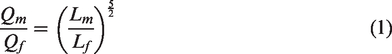
first put forward the dimensional relationships between fluid dynamic variables. By holding Froude number constant, the dimensional relationships between reduced scale and full scale are described by equations (1) to (3) as follows
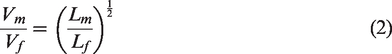
According to fire research related to vertical shaft, stack effect was almost the only mechanical factor studied, but the effect of coupling multiple forces on fire smoke behaviour has been seldom considered. In order to investigate the influence of the multi-driving force of the shaft on fire and smoke in a multi-storey building, a 1/4 scale three-floor platform was designed and built, as shown in Figure 1. The specific dimensions are shown in Figure 2. A 3.0 m high shaft (0.6 m × 0.8 m × 3.0 m) is situated on one side of the platform. The vertical shaft is connected to the corridor (4.4 m × 0.5 m × 0.75 m) through a front chamber (0.5 m × 0.8 m × 0.8 m). Each floor inside the platform is connected and separated by controlling the status of shaft door (0.5 m × 0.6 m), front chamber door (0.5 m × 0.6 m) and corridor door (0.5 m × 0.75 m). The flame shape and smoke field can be observed from fireproof glasses which are located on one side of vertical shaft and front chamber. The top vent of vertical shaft can be implemented with a variety of ventilation functions, including a positive pressurized air supply, negative pressure air exhaust and fully closed condition, by controlling two fans and a number of control valves. A rectifying section is arranged at the top of the shaft to achieve uniform distribution of the air in the cross-section.

The experimental rig. (a) Sideview of the platform, (b) location of fireproof and shaft, (c) ventilation system of vertical shaft and (d) corridor of each floor.
Schematic and measurement points of the three-floor building. (a) Front view of the platform and (b) top view of the platform.
Parameters arrangement of the experiment
Propane burner was used as the fire source and controlled by a high precision mass flow meter (manufacturer: Sevenstar; range: 0–30 SLM; accuracy: ±0.35% S.P. (≤35% F.S.) and ±1% S.P. (≥35% F.S.)). This was located at the centre of the first floor front chamber. Fifty-one K-type thermocouples (manufacturer: Shanghai Feilong Meters & Electronics Co., Ltd; range: 0–900°C; accuracy: ±1.5°C) with 1 mm in diameter were arrayed in this three-floor building model. The schematic of measuring points is shown in Figure 2. Nine of these measuring points were located in the shaft at different heights: 0.22, 0.59, 0.69, 1.0, 1.45, 1.55, 1.86, 2.31 and 2.41 m. Eighteen of these measuring points were located in each floor ceiling arranged uniformly with an interval of 0.88 m. The rest of these measuring points were arranged at fire floor. Seven velocity measuring points (manufacturer: Kanomax; range: 0–9.99 m/s; accuracy: ±0.01 m/s) were installed in the model. Three of these were located at the top vent of the shaft and the rest of them were located in the fire floor corridor, at heights of 0.2, 0.35, 0.5 and 0.6 m. A laser sheet (manufacturer: Changchun New Industries Optoelectronics Technology Co., Ltd; power: 2 W; wavelength: 532 ± 1 nm) was used to enhance the smoke field of the fire floor.
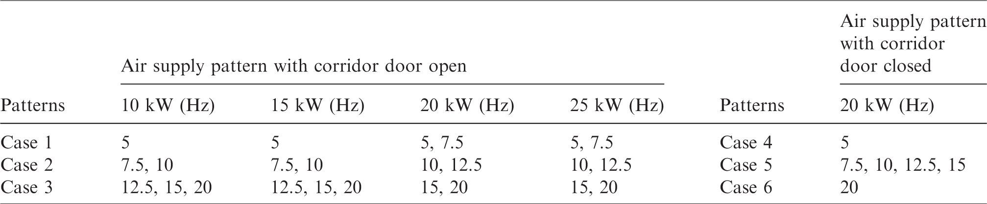
The ventilation conditions of the conducted experiments include six air supply parameters: 5 Hz (0.34 m/s), 7.5 Hz (0.44 m/s), 10 Hz (0.55 m/s), 12.5 Hz (0.71 m/s), 15 Hz (0.89 m/s) and 20 Hz (1.25 m/s) and three air exhaust parameters: 7 Hz (0.5 m/s), 14 Hz (0.91 m/s) and 21 Hz (1.3 m/s), and the shaft was closed completely. The stability and uniformity of the air supply fan are shown in Figure 3. From Figure 3, we can reasonably assume that the velocity of air ventilation was uniform at the same height. Experimental cases and details are summarized in Table 1. Two digital cameras (manufacturer: Canon; range: 2010 megapixel) were used to record flame behaviour and smoke field. These cameras were located in front of the chamber through the fireproof glass and at the end of the corridor door, respectively. The door of the non-fire floor was opened in all experiments. To ensure that the experimental data were reliable and accurate, each experiment was repeated two times and the results presented good repeatability with measurement uncertainties of less than 5%.
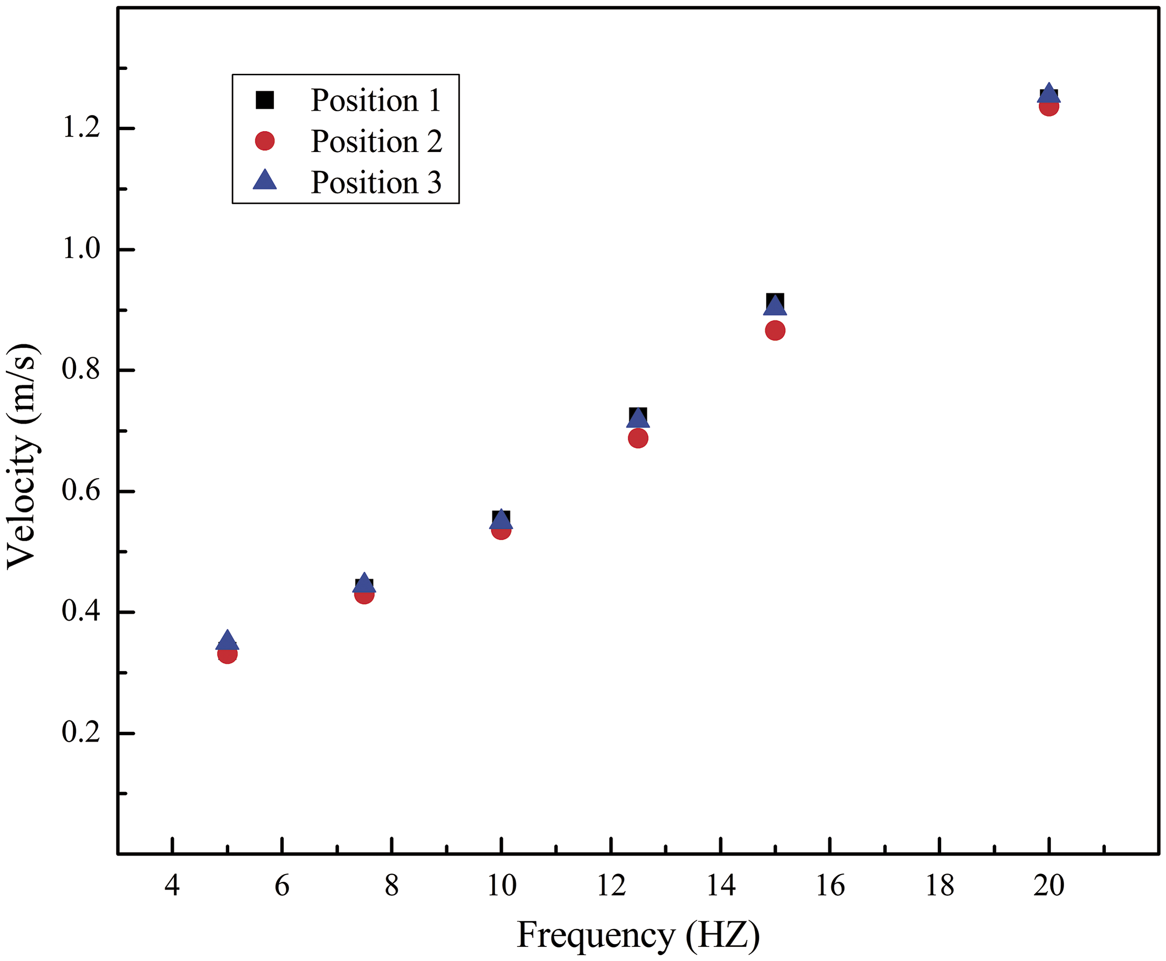
The velocity distribution of three positions with different frequency.
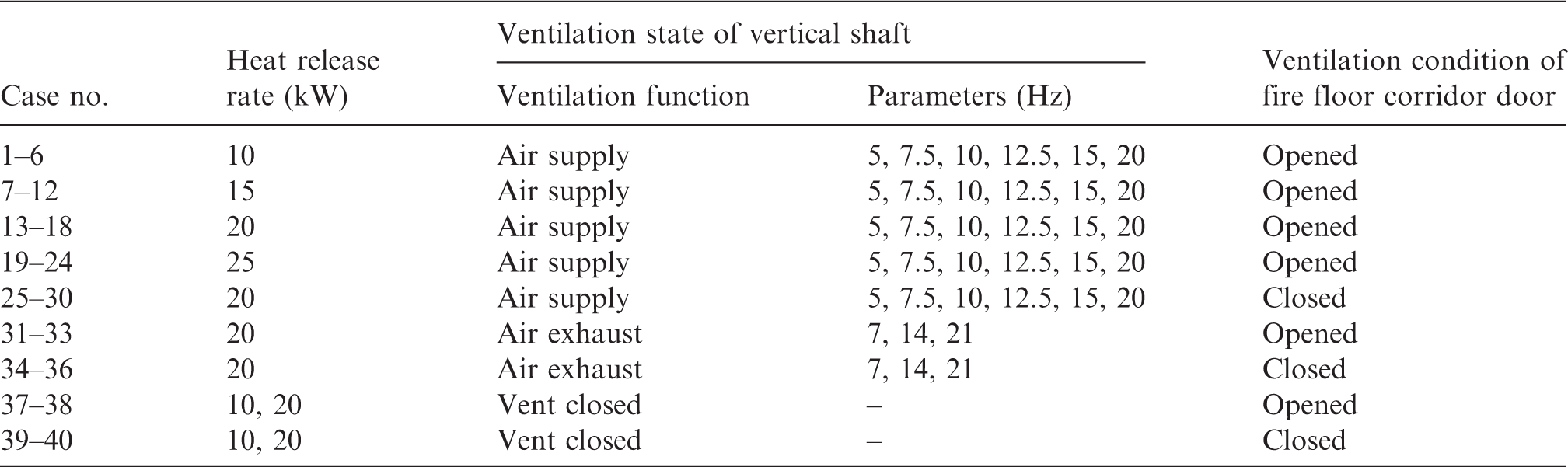
Experimental details.
Results and discussion
Fire behaviours
Fire tilt direction with time under different ventilation conditions
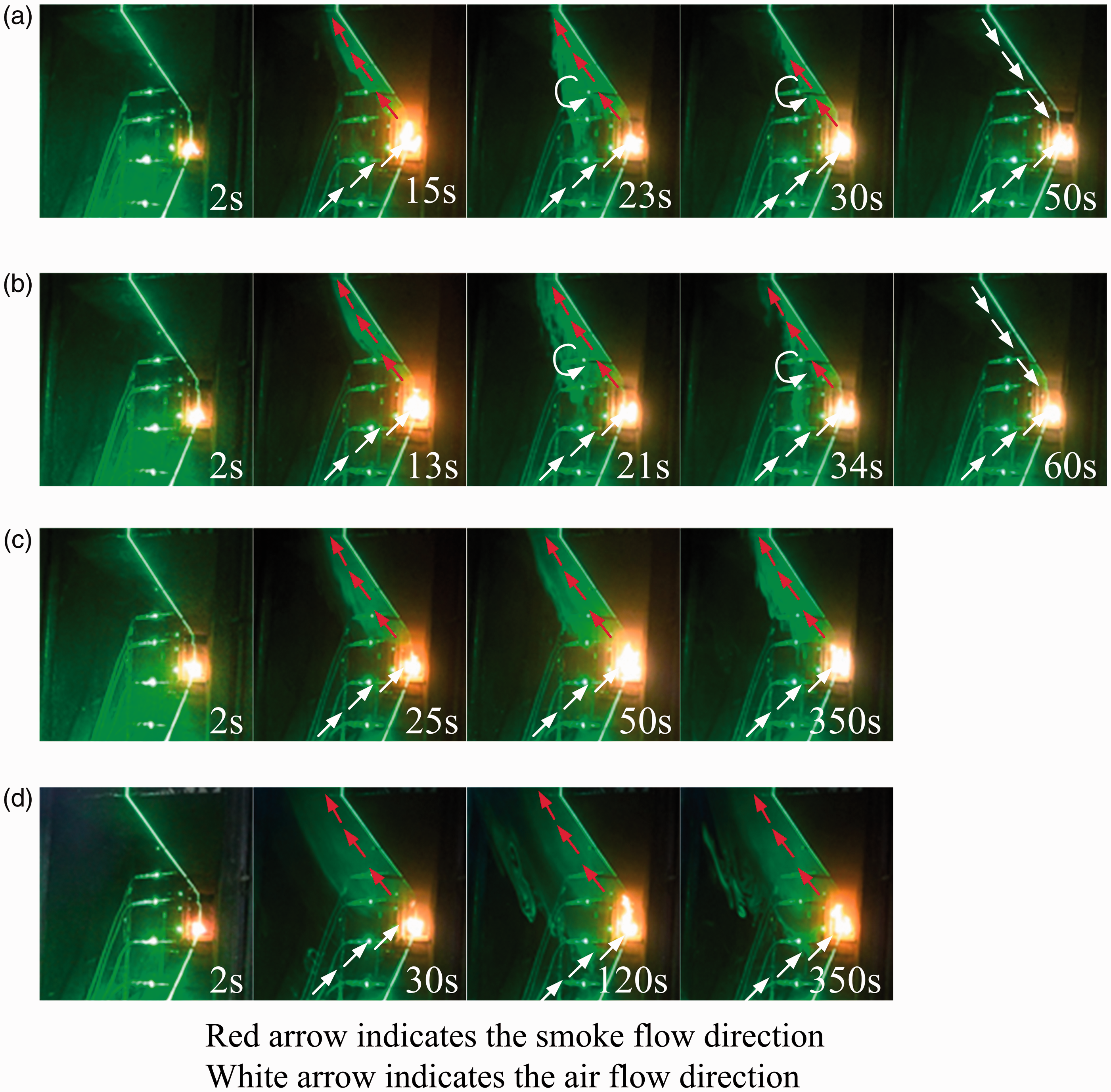
From the videos, the flame shape was observed to vary with ventilation parameters. Figure 4 shows the transient flame shape of cases 1–6 with positive pressurized air supply conditions under the heat release rate of 10 kW. From Figure 4(a), when air supply parameter was 5 Hz, the flame was relatively short and vertical (2 s) after ignition. At the time of combustion, an accumulated smoke in front chamber flowed to both sides (first floor corridor and vertical shaft). Generally, smoke movement in early stage was mainly affected by two driving forces (plume buoyancy induced by smoke itself and inertia force induced by air supply ventilation). As the effect of inertia force in this case (5 Hz) was small enough in comparison with thermal buoyancy, more smoke flowed into the shaft and rose up easily. Due to the existence of upper opening and a huge vertical temperature difference, a stronger stack effect was formed. Accordingly, under the influence of stack effect, a lot of ambient air would be flow into the building through corridor door of fire floor to keep pressure balance inside of the building. The flame gradually tilted from vertical to shaft direction and the tilt angle was increased with time until a steady state (100 s) was reached. As shown in Figure 4(b), the flame tilted slightly towards the direction of the corridor during a short period (1–25 s). However, after then, the flame tilt direction changed slowly and moved towards the shaft (180 s). However, it should be noted that the flame tilt angle was noticeably smaller than in case 1. This was mainly due to a weakening of stack effect and increasing of inertia force when the air supply parameter changed from 5 to 7.5 Hz. Different from the case 1 and case 2, the flame inclined towards the corridor during the ignition stage, and this circumstance lasted during the whole experimental case (see Figure 4(c)). When more smoke flowed into the shaft, the stack effect became relatively stronger. The flame tilt angle gradually reduced during 1–340 s. When the ventilation velocity was increased, the stack effect was weakened correspondingly due to the higher inertia force. Therefore, it became more difficult for the smoke to spread to the shaft. As shown in Figure 4(d) to (f), the flame tilted towards the corridor all the time after ignition had started.
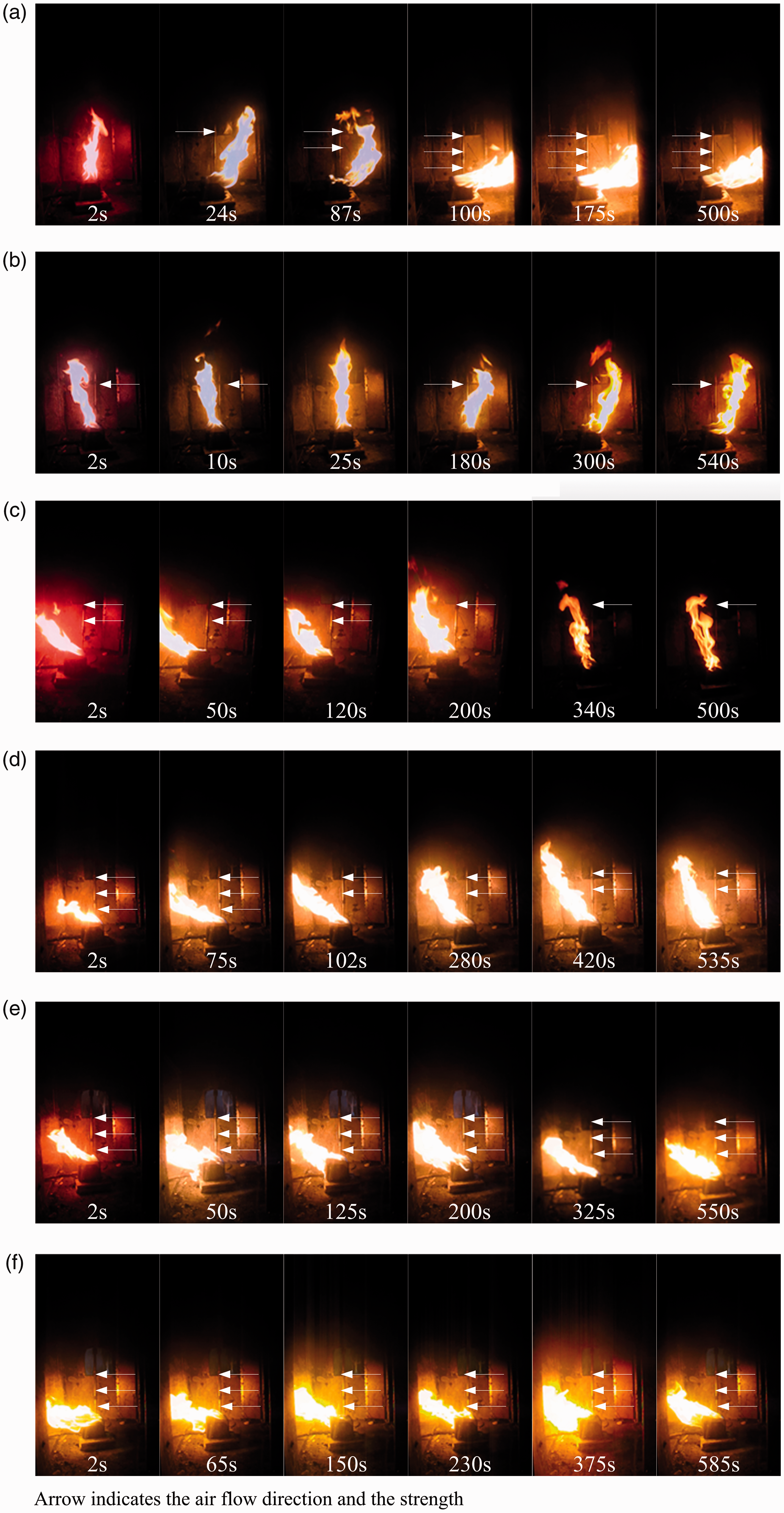
The process of the flame tilt with different ventilation conditions (10 kW). Air supply parameters: (a) 5 Hz, (b) 7.5 Hz, (c) 10 Hz, (d) 12.5 Hz, (e) 15 Hz and (f) 20 Hz.
Flame tilt angle distribution at steady state
In addition to flame tilt direction, the flame tilt angle is also a concern in this study. The tilt angle of flame (
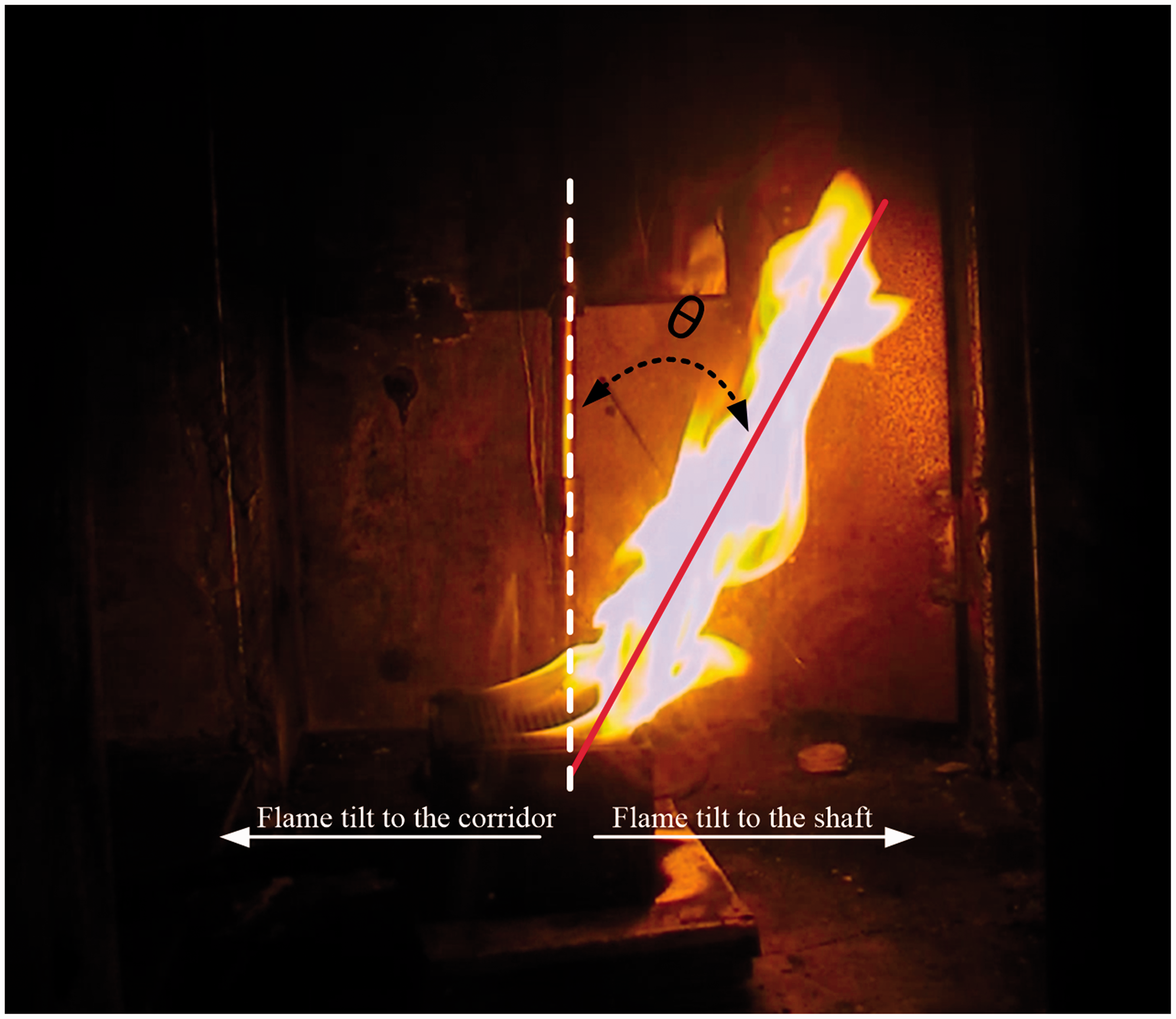
Diagram of the flame angle.
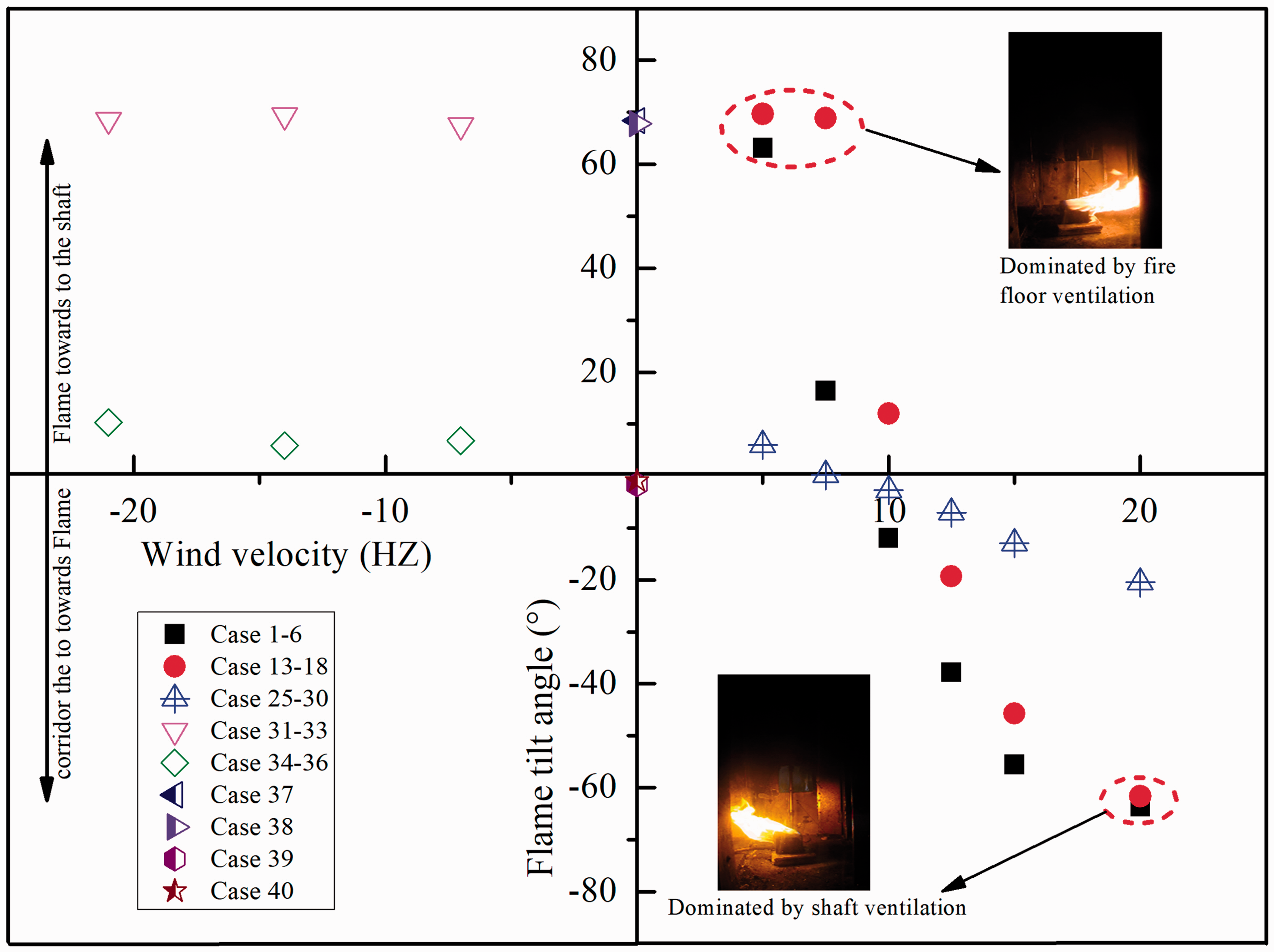
Flame tilt angle at steady stage.
From Figure 6, when the top vent of the shaft has no ventilation (closed, cases 37–40) and air exhaust condition (cases 31–36), the flame tilt angle was mainly determined by the first corridor door ventilation state. When the corridor door was fully closed, ambient air was not able to enter the corridor, and the flame rose vertically no matter how much the heat release rate of the burner. However, compared with no ventilation condition, the flame tilt angle of air exhaust condition was slightly larger due to the existence of negative pressure induced by air exhaust fan. Whereas, when the corridor door was open, the flame was close to the horizontal direction (70°) due to the stronger stack effect. From Figure 6, the air exhaust cases were shown to barely have an impact on the flame tilt angle.
From Figure 6, with air supply ventilation condition of vertical shaft (cases 1–30), flame tilt angle was affected by several factors, including ventilation state of corridor door, air supply parameter and heat release rate. Under natural ventilation condition of corridor door (cases 1–24), the flame tilt angle was shown to produce a huge fluctuation (from 65° to −65°). When the heat release rate was 10 kW, in case 1, the effect of stack effect was significantly greater than air supply pressure and the flame tilt angle was about 63°. When the air supply was increased, the smoke flow into the shaft was restricted and the stack effect was weakened correspondingly. From 5 to 7.5 Hz, the flame angle was decreased by almost 50°, but the flame tilt still moved towards the shaft. However, when the air supply was large enough and reached 10 Hz, the flame tilt direction was changed and the angle was −12°. As the air supply was increased from 10 to 20 Hz, the flame tilted towards the corridor and the tilt angle was increased gradually. This phenomenon indicates that the effect of air supply pressure was larger than stack effect. As shown in Figure 6, with an increase in heat release rate, the stack effect was enhanced by the thermal plume. In cases 13–18, with 20 kW of heat release rate, the flame tilt angle exceeded the conditions that produced 10 kW of heat release rate under the same air supply ventilation. Therefore, the flame was more inclined to the direction of the shaft with a larger heat release rate. When the flame tilt from shaft to corridor happened, the condition that produced 20 kW heat release rate required a larger air supply parameter as compared with the condition that produced 10 kW heat release rate. From Figure 6, the decisive factors that determined the distribution of flame tilt angle can be divided into three situations: the fire floor ventilation domination stage (stack effect domination stage), the air supply domination stage and the intermediate stage, respectively.
When the corridor door of fire floor was closed (cases 25–30), the stack effect was weakened severely because of the poor ventilation. In this condition, air supply ventilation was the only vital factor that influenced the flame tilt angle. The flame tilt angle was shown to vary little and less in comparison with the state of door opening (cases 1–24). When the air supply was increased, the flame was influenced by the air that flowed into the front chamber and moved towards to the corridor slightly.
The prediction of migration path of a three-floor building based on fire-related parameters
Smoke development of the fire floor
Figures 7 and 8 show the smoke movement process with time on fire floor under different ventilation conditions and heat release rates. The smoke field was enhanced by laser sheet.30,31 From Figure 7(a), smoke flowed into the first corridor after ignition, and the laminar fluid was stable (20 s). During the progress of combustion, the outside air flowed into the fire floor due to the generation of the stack effect. After that, the bottom of laminar smoke was subjected to forced air entrainment and turned into a turbulent fluid (35 s). After 65 s, the smoke back-layering flow happened as was reported in the previous study.32,33 Finally, no smoke existed in the fire floor (80 s) and all the smoke moved into the upper spaces through the shaft door. When the air supply reached 7.5 Hz, the ventilation pressure was shown to weaken the influence of stack effect to some extent. Accordingly, the resistance of spreading of the smoke in the fire floor was relatively small. As shown in Figure 7(b), the smoke spread along the corridor and spilled out to the outside all the time. The smoke layer thickness was about 0.15 m. When the air ventilation parameter was 10 Hz, the ventilation pressure hindered the smoke moving to upper space seriously. The smoke layer height was about 0.55 m. When the air ventilation parameter exceeded 10 Hz, the smoke filled the entire corridor space, and the smoke particle concentration was shown to increase with a corresponding increase in the ventilation condition.

Smoke field on the fire floor with different ventilation parameters (10 kW). Air supply parameters: (a) 5 Hz, (b) 7.5 Hz, (c) 10 Hz and (d) 12.5 Hz.
Smoke field on the fire floor with different ventilation parameters (25 kW). Air supply parameters: (a) 5 Hz, (b) 7.5 Hz, (c) 10 Hz and (d) 12.5 Hz.
From Figure 8(a), the smoke movement process was similar to case 1. However, due to the stronger stack effect, the time of the back-layering flow phenomenon (30 s) was largely earlier compared with case 1 (65 s). Different from case 2, the back-layering flow phenomenon still existed after 34 s in case 20 (see in Figure 8(b)), although the air supply velocities in both are the same. Therefore, the greater the heat release rate of the burner, the earlier and more likely the back-layering flow phenomenon would happen. From Figure 8(c), the smoke layer height was stable and the smoke remained in a laminar flow state. When the air supply was increased, the smoke layer height was gradually increased (12.5 Hz with a smoke layer height of 0.4 m, 15 Hz with a smoke layer height of 0.5 m, 20 Hz with a smoke layer height of 0.75 m).
Based on those analyses, we found that there exists a critical air supply velocity when the smoke back-layering phenomenon happened. This critical value was determined by the heat release rate. When the heat release rate was 10 kW, the critical velocity value was between 0.34 and 0.44 m/s. However, when the heat release rate reached 25 kW, the critical value was between 0.44 and 0.55 m/s. In general, the critical velocity was increased with a corresponding increase in heat release rate.
Velocity distribution at corridor door under different air supply ventilation conditions
Due to the influence of air supply ventilation and heat release rate difference, the boundary condition has a huge effect on the spreading of smoke. Figure 9 shows the average velocity distribution at corridor door of the first floor. The positive value represents the influx of air from corridor door, and the negative value indicates the smoke was spilling out to the outside. The altitude of 0 m/s was roughly the physical boundary between fresh air and smoke. As shown in Figure 9(a), the outside air velocity distribution was uniform in vertical direction at 5 Hz and was maintained at 0.57 m/s. It indicates that the outside fresh air filled the entire cross-section of the corridor (see Figure 7(a)). When the air supply was 7.5 Hz, two directions and kinds of fluids appeared in the corridor, which are the lower part of outside air and upper smoke, respectively. There was still a large amount of air flowing into the building. As shown in Figure 9(c), only a small portion of air flowed into the building. Accordingly, a large amount of smoke overflowed to the outside space instead. When the air supply increased to 12.5 Hz or higher, the velocities were all maintained negative. Therefore, no air flowed into the corridor, and the smoke filled the whole corridor space. The absolute value of the smoke velocity was increased steadily as the air supply was increased. Different from the air supply condition of 5 Hz, the distribution of velocity produced a certain degree of non-uniformity in the vertical direction. From Figure 9, for the same air ventilation parameter, the height of physical boundary layer between smoke field and air was increased with an increase in heat release rate. With an increase in the heat release rate, more air supply ventilation was required to make the smoke to spill out to the outside space from fire floor. Besides, with larger heat release rate, a greater velocity of the air inflow and a smaller velocity of the smoke outflow occurred. According to the Froude modelling law (equation (2)), the velocity gradient of the real building structure would become larger than the scaled model.
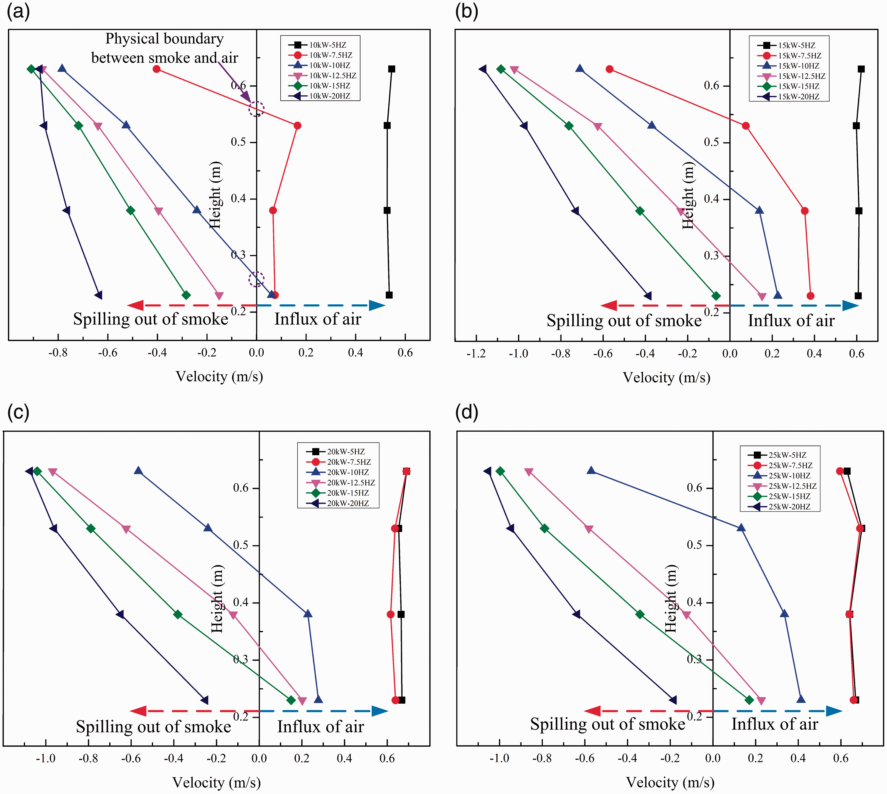
Average velocity distribution at corridor door on the fire floor. (a) 10 kW, (b) 15 kW, (c) 20 kW and (d) 25 kW.
Temperature distribution at ceilings on each floor
Figure 10 shows the average temperature of ceilings on each floor. From Figure 10(a), on the fire floor, the temperature distribution can be divided into two conditions. One of the conditions was that the temperature was close to ambient temperature only in the case of 5 Hz air supply. However, when the ventilation parameter was over 5 Hz, the temperature increased dramatically and reached around 100°C. Due to the variation in the flame tilt angle, the temperature at the test point – close to the vertical shaft – was shown to produce a huge fluctuation. On the third floor, the temperature distribution was roughly opposite to the fire floor and also could be divided into two parts. The top floor reached the highest temperature level by 40°C at 5 Hz. The temperature then declined drastically once the air supply condition was larger than 5 Hz. On the second floor, the same with the third floor, the temperature of 5 Hz air supply ventilation was also kept at the highest level. However, different from other floors, the temperature was more sensitive to changes in the air ventilation condition. The temperature declined slowly as air ventilation was increased. Besides, considering the temperature distribution on the third floor and air supply condition, the temperature in the case of 10 Hz air supply was higher than in the case of 7.5 Hz air supply.
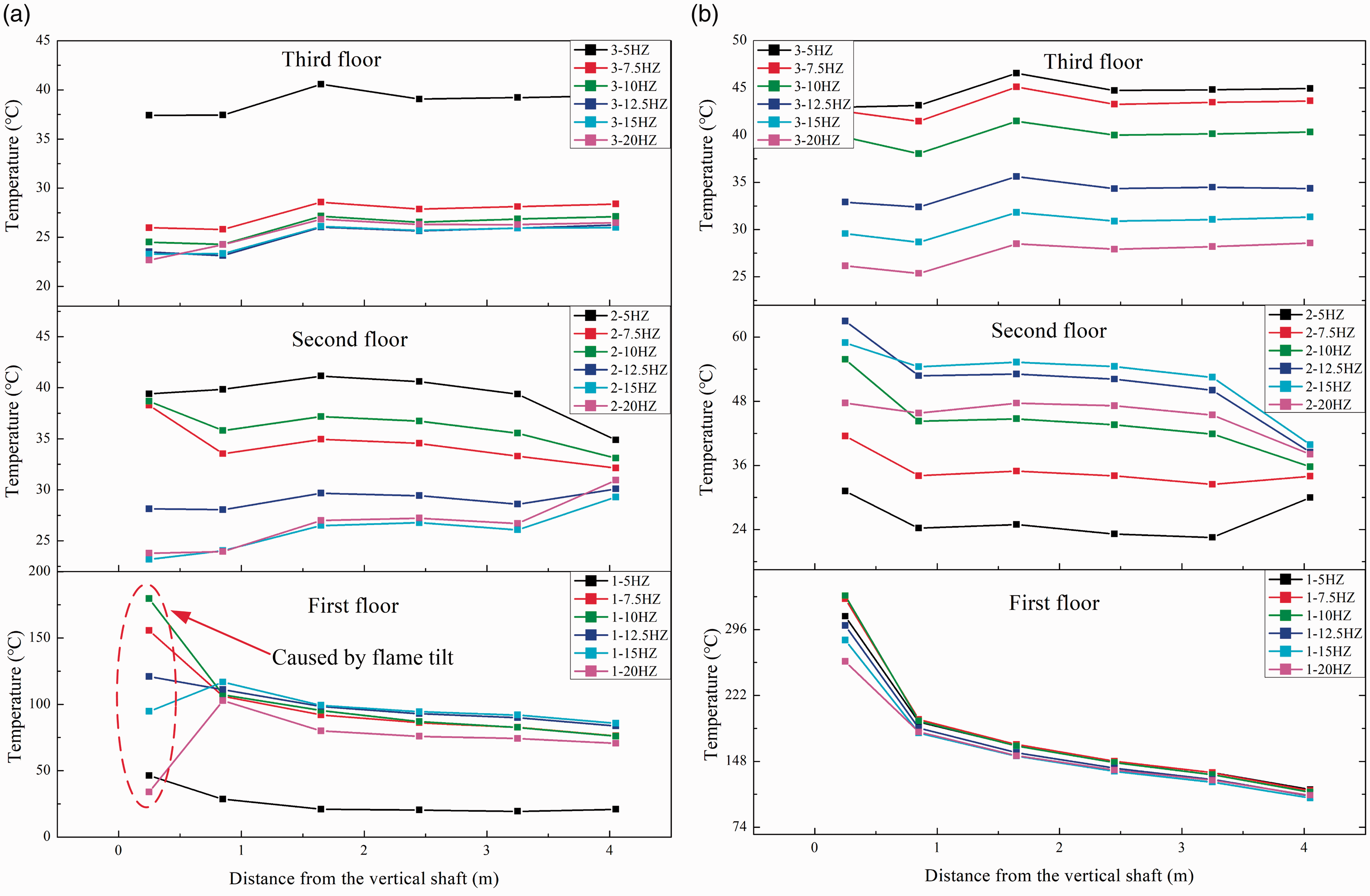
The temperature distribution of ceilings on each floor. (a) Cases 1–6 and (b) cases 25–30.
When the corridor door at fire floor was closed, the temperature distribution is shown in Figure 10(b). On the first floor, temperature was always kept at a high level whatever the ventilation state of the vertical shaft. Therefore, the ventilation state of the corridor door was shown to have a huge impact on the fire floor, especially under conditions of 5 Hz air supply. From the Figure 10(b), the temperature on the second and third floors gradually changed as the ventilation was increased, but the mechanism of each floor was totally different to former cases (cases 1–24). On the second floor, temperature was increased with an increase in the air supply. The temperature declined with an increase in the air supply on the third floor. In general, if air ventilation state on the fire floor was not good enough (corridor door closed), the temperature on the first floor was hardly affected by the shaft ventilation parameters and it would remain at a high level of danger.
Migration path prediction based on fire-related parameters
Based on the above analysis, it is easy to conclude that the degree of impact of smoke on each floor is different when various ventilation conditions are adopted. It implies that the smoke migration path in this three-floor building should be different as well. According to the analysis of flame tilt characteristics and fire smoke-related parameters, we naturally and reasonably speculate the migration path of smoke under a certain ventilation condition. Figure 11 shows the typical cases of smoke migration path under air supply ventilation condition. Cases 1–3 present the possible migration paths with corridor door opening. When the air supply was low enough, smoke can easily overcome the restriction of air ventilation and flow into the upper space. Besides, the smoke on the upper level exacerbated the strength of stack effect, resulting in a large number of air influx in the fire floor and all of the smoke moved to the upper floors (as shown in Figure 11(a)). As shown in Figure 11(b), when air ventilation was increased, the effect of air supply was higher than the stack effect at the height of the third floor. The smoke driven by buoyancy would not be able to enter third floor space, and fresh air produced by air supply fan would flow into this floor instead (as shown in Figure 11(b)). When air supply ventilation was large enough, the effect of air supply was much greater than the stack effect and smoke could not flow into the upper space through the shaft door (as shown in Figure 11(c)). Cases 4–6 show the possible migration paths with first corridor door closed. Smoke filled the entire first corridor all the time due to bad ventilation. Besides, most of the smoke flowed into the upper space through the shaft door. When the air supply was low, almost all the smoke flowed out through the third floor, and the function of the second floor was just as an air inlet (see Figure 11(d)). With the increase of air supply velocity, smoke flowed into the second floor. However, in order to keep the pressure balance between the air supply pressure and thermal expansion, smoke would also flow into the third floor (case 5). If the air supply ventilation pressure was large enough, the supplied air would then overcome the thermal expansion effect totally. Almost all the smoke and a small portion of the supplied air would flow into the second floor. The third floor would then be filled by the supplied air. Table 2 shows experimental tests corresponding to six cases with migration paths.
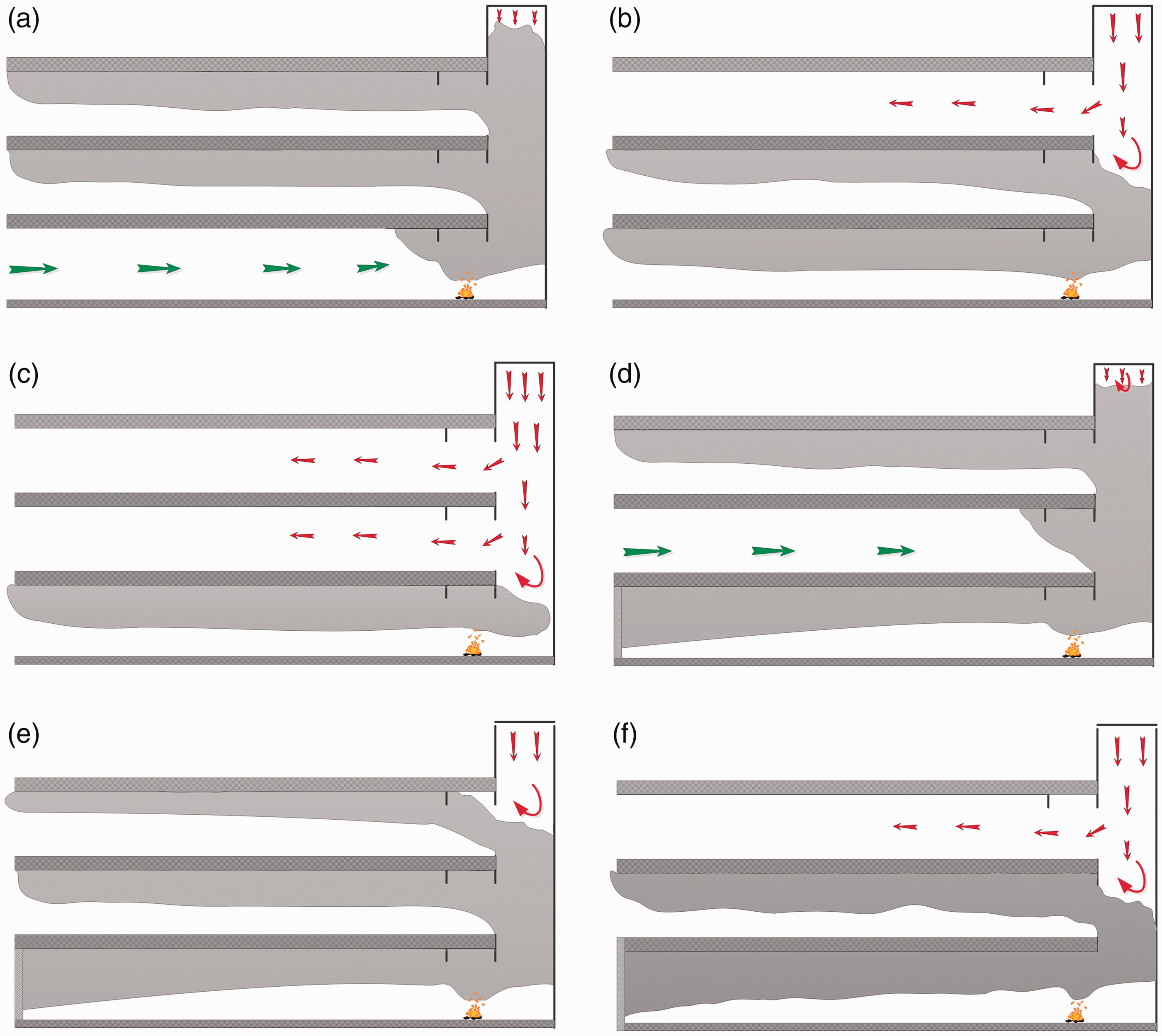
The migration path with different air supply conditions. (a) Case 1, (b) case 2, (c) case 3, (d) case 4, (e) case 5 and (f) case 6.
Experimental tests of cases 1–30 corresponding to different migration paths.
Critical condition to determine the flame tilt direction
Based on the above analysis, the flame tilt direction is mainly determined by air supply condition and stack effect. The air supply pressure can be calculated by equation (4) as follows17,18,20

The pressure induced by the stack effect in the vertical shaft can be calculated by equation (5) as follows
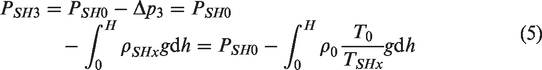

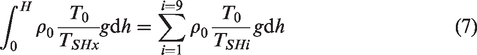
In order to simplify the calculation, we assumed that the temperature was uniform at a certain height and the integral can be expressed as equation (7)
Different from the traditional long straight corridor with both side opening, the fire floor was connected with a vertical shaft which was given a positive air pressure (air supply condition). The effect of corridor should not be ignored in the current model. Smoke was difficult to spill out to the outside along the corridor as the stack effect occurred. If spillover happened, the pressure difference, 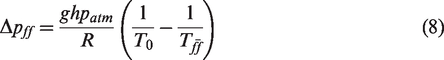
The pressure difference inside and outside of the top of the shaft was determined by equation (9) as

In order to confirm the flame tilt direction of the thermal plume, a non-dimensional number, 
Substituting equations (4) to (9) into equation (10) yields equation (11)
According to experimental data and theoretical analysis,
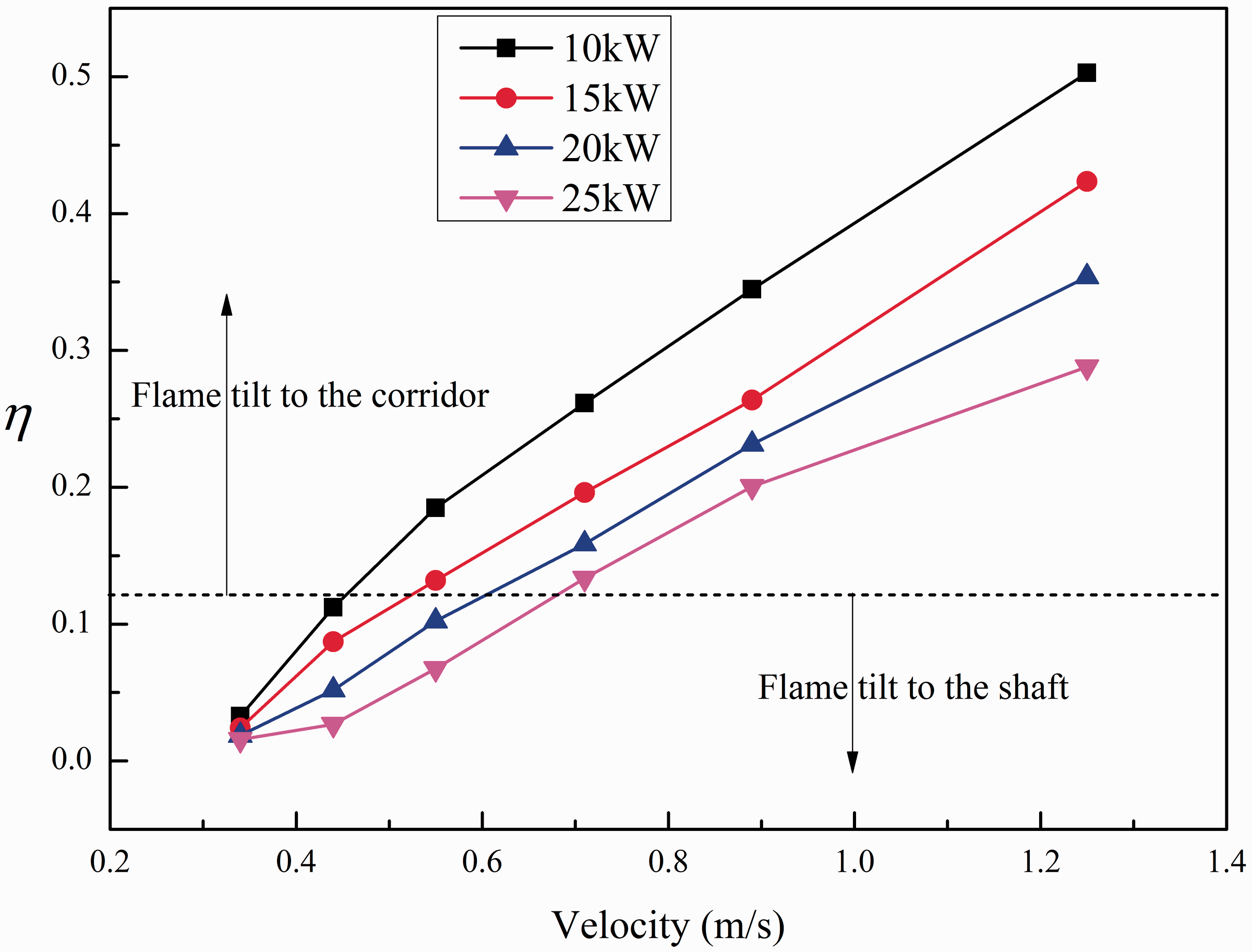
Values of
Conclusions
In this paper, fire behaviours and smoke characteristics in a multi-storey building with different ventilation conditions were investigated using a scaled three-floor building model. The results are summarized as follows:
The flame tilt direction is more affected by the shaft ventilation, heat release rate and ventilation state of the fire floor. The tendency of the flame is more inclined to the direction of the shaft with a greater heat release rate. Whereas the flame is more tilted to the corridor with a greater velocity of air supply ventilation. Besides, flame tilts to the shaft all the time under air exhaust conditions. If the corridor door on the fire floor is closed, the flame tilt is approximately vertical. The distribution of flame tilt angle under air supply conditions can be divided into three stages. The fire floor ventilation domination stage indicates that the stack effect is the most vital factor affecting the flame tilt angle. The air supply domination stage indicates that air pressure is the pivotal factor. The intermediate stage indicates that the flame tilt angle is determined by the interaction of both factors. At this stage, the flame angle varies greatly. Based on detailed analysis of fire behaviours and fire-related parameters, six typical migration paths were identified with different ventilation conditions. The corresponding relationships between experimental cases and migration path are given in Table 2. Besides, back-layering flow phenomenon happened in some cases. In order to verify the flame tilt direction, a dimensionless number
Footnotes
Authors’ contribution
All authors contributed equally in the preparation of this manuscript.
Declaration of conflicting interests
The author(s) declared no potential conflicts of interest with respect to the research, authorship, and/or publication of this article.
Funding
The author(s) disclosed receipt of the following financial support for the research, authorship, and/or publication of this article: This work was supported by National Natural Science Foundation of China (No. 51636008 and 51476158), the Key Research Program of the Chinese Academy of Sciences (No. QYZDB-SSW-JSC029) and the Fundamental Research Funds for the Central Universities (No. WK2320000035). The authors deeply appreciate the supports.