This investigation focuses on the nonlinear interaction of a structural framework with six degrees of freedom (DOF) when it is excited externally. The response is significantly influenced by several critical zones of internal resonance arising from the system’s nonlinearity. The multiple time scales perturbation method (MSPM) is employed to derive analytical solutions and examine all resonance cases. Frequency response equations corresponding to the most critical resonance scenarios are developed for stability analysis. MATLAB software (ode45) is used to analyze the system both before and after incorporating a positive position feedback (PPF) controller. For the vibrating system and controller, the effects of various parameters are examined numerically, and the obtained results confirm the accuracy of the approximate analysis. Finally, comparisons with previously published work demonstrate the consistency of the proposed approach. The novelty of this work lies in integrating MSPM-based analytical modeling with a PPF control strategy to achieve near-complete vibration suppression in nonlinear multi-DOF systems, providing a validated and practical framework for advanced structural vibration control.
One of the deadliest pollutants that can harm both the home and workplace is vibration. Because of their low frequency and numerous polarizations, environmental vibrations frequently affect engineering structures, especially lightweight ones, and are challenging to suppress. Vibration suppression, cancellation, and absorption techniques have been studied for decades. Most of the time, vibration suppression is carried out after the structure has been constructed and is in use. The issue is resolved by either introducing viscoelastic material with certain dampening qualities (vibration isolators) or by implementing the necessary masses into the structure (vibration absorbers). The structural weight is raised, the system’s rigidity is altered, and the vibration suppression effect is not achieved. These are the primary shortcomings of the recommended approaches.
Achievements in the fields of telecommunications, earth sciences, and aerospace space stations, space telescopes, and observation increase the need for large-scale and high-precision spatial arrangements. Large deployable space structures that can change from a compact folded state to an anticipated deployed shape are frequently utilized as astrophysical missions approach the launchers’ limits.1 Vibration suppression of large deployable space structures has been the subject of a vast number of publications, which may be broadly divided into two categories: active control and passive suppression. Many researchers have successfully applied the active vibration control technique for vibration attenuation of beams, plates, and shells.2 One of the frequent uses of passive damping systems is viscous damping, due to its consistent damping, affordability, and ease of setup. The Hubble telescope was the first to use a reaction wheel to separate micro-vibrations.3 Since isolation systems isolate vibration to shield instruments and equipment from a variety of vibrating environments, they must have high stability and notable isolation performance. Different designs and control strategies are used for various vibration suppression techniques for various applications; for instance, energy transfer between various vibration modes,4–9 employing absorbers that dampen vibration,10–12 or applying active/semi-active vibration methods for regulation, etc.13–15
Generally speaking, in vibration isolation, elements with lesser restoring forces yield superior isolation effectiveness and a lower system natural frequency, particularly in microgravity situations in aeronautical engineering.16–18 In order to better understand how multi-DOF systems behave in resonant situations, the movement of a 3DOF dynamical system close to resonances was examined.19 To learn more about intricate oscillatory systems, the authors also looked at a 2DOF dampened SP, in which the support point is limited to an elliptic route.20 Refs. 21, 22 have conducted both theoretical and experimental research on such systems with a quadratic vibration absorber under parametric and external excitations. Because of its great precision, large bearing capacity, and smooth motion, the 6-DOF Stewart platform is a good parallel manipulator. Numerous active and passive vibration isolation devices have used it.23 The Stewart platform of cubic configuration is simpler to handle and can simplify the kinematic relationships in all 6-DOF platforms.24 All six degrees of freedom (DOF) would be impacted by vibrations; therefore, multi-DOF vibration isolation systems should be employed to meet the strict criteria and provide reliable performance in some application domains, such as semiconductor production.25 To improve vibration attenuation performance, this research focuses on a 6-DOF active vibration isolation system powered by the VCMs. The flight control of an F-16 aircraft derivative and an HDD servo system were successfully implemented to improve the dynamic characterization of the composite nonlinear feedback (CNF) control law.26,27 El-Sayed and Bauomy28,29 highlighted on the PPF approach for reducing upward transport motions. They explained how the PPF can lessen the approaching framework’s vibration. They also revealed how the Nonlinear Integral Positive Position Feedback (NIPPF) can reduce the system’s high vibration amplitude.30 They consider how the giant magnetostrictive actuator (GMA) executes when its vibration is tightly controlled by a PPF damper. The approach used here uses one of the most well-known perturbation techniques to mathematically search for the approximate solution for the motion equations of the GMA with the PPF damper. Our method for obtaining analytical results is the second-order approximation of MSPM. In Ref. 31 the controlled system has been analytically solved using the MSPM. All of the numerical discussions have been completed and made clearer using MATLAB and MAPLE possibilities. The effect of changing the parameter values on the amplitude has been investigated using the frequency response curves. An approximate first-order solution has been achieved with the MSPM. The stability and steady state sensitivity of the system at the primary resonance scenario () are regarded as the worst resonance and addressed using the frequency response function technique. The chaotic behavior of the nonlinear dynamical system and the numerical solution for different parameter values are also investigated. To achieve simulation results, MATLAB applications are used.32 The mechanical response of a unique auto-parametric two-degree-of-freedom dynamical system to external torque and force is the primary focus of this work. Following the classification of all occurring resonance cases, two of them are analyzed simultaneously. To demonstrate the beneficial impact of various factors on the behavior of the modified phases and amplitudes, the pertinent system of stimulation equations is solved numerically.33 Lagrange’s equations are utilized to derive the nonlinear differential equations that regulate this system. The multiple-scales method (MSM), which yields higher-order estimations, is then used to derive their analytical solutions (AS). Resonance examples are used to determine the solvability requirements and distinguishing exponents. The stability of the fixed points that correspond to the steady-state solutions is evaluated using the Routh–Hurwitz criterion (RHC).34 The stability characteristic of the nonlinear dynamical motion of a vibrating cart with two degrees of freedom (DOFs) is investigated in Ref. 35. The matching fixed points are used to compute the steady state solutions. The obtained solutions are contrasted with the numerical solutions (NSs) of the system’s initial equations and graphically presented to show the effects of adjusting the system’s parameters. In Ref. 36, an inventive framework for comprehending frequency response and nonlinear stability across stable and unstable ranges is offered by the analysis of resonance scenarios using characteristic exponents and solvability conditions in conjunction with the use of Routh-Hurwitz criteria (RHC) for stability evaluation. In Refs. 37, 38, the controlled linear equivalent methodology was analyzed using the multiple time-scales method (MTSM). The robust design of the prototype was depicted in multiple diagrams. The fourth-order Runge-Kutta method (RK4) was used to confirm the calculated solutions numerically, and the results showed a good correlation. Both before and after control was applied, the nonlinear patterns’ stability and steady state amplitude were examined. Furthermore, under various controller and system parameter settings, frequency response curves (FRCs) and ideal device topologies were assessed. Solving ability standards and characteristic exponents under resonant conditions are derived from Refs. 34–43. A deeper understanding of the behavior of the system is obtained by analyzing the stability of the steady-state solutions using frequency response curves and the Routh–Hurwitz criterion. The fourth-order Runge–Kutta (4RK) strategies are used to obtain the numerical solutions (NS) of the GS, which follow a comparison to the approximation solutions (AS). References 44, 45 study analyzes the planar dynamics of a two-degree-of-freedom (2DOF) auto-parametric pendulum with damping. The equations of motion are derived using Lagrange’s method and solved approximately via the method of multiple scales (MMS). Different resonance cases are investigated, and stability regions are determined. Time histories, amplitudes, and phase trajectories are presented to illustrate the system’s behavior, showing that the system maintains stable performance over a wide range of parameters.
The current project aims to analyze and build a three-degree-of-freedom model in order to take such interactions into account. The system has been studied under combined excitations in a new six-DOF model after PPF techniques were added. First-order solutions of the system can be obtained with the use of the multiple time scale perturbation (MTSP) technique. In order to determine the stable and unstable zones of each curve for the measured simultaneous resonance case, the stability analysis was accomplished numerically for all FRCs. To demonstrate how much more vibration reduction the system with PPF control produces than with Active control, a comparison between the two is provided. To demonstrate the response with and without control, time histories of the controller and the main system are depicted. The PPF controller is quite good at lowering the nonlinear vibrations of the system’s amplitudes, according to numerical results. It has been demonstrated that analytical and numerical results can be compared. Additionally, a comparison of the published papers that are now available has been given. Lastly, a few significant uses for the model under study are mentioned.
2. Creating problem equations
2.1. An explanation of the model
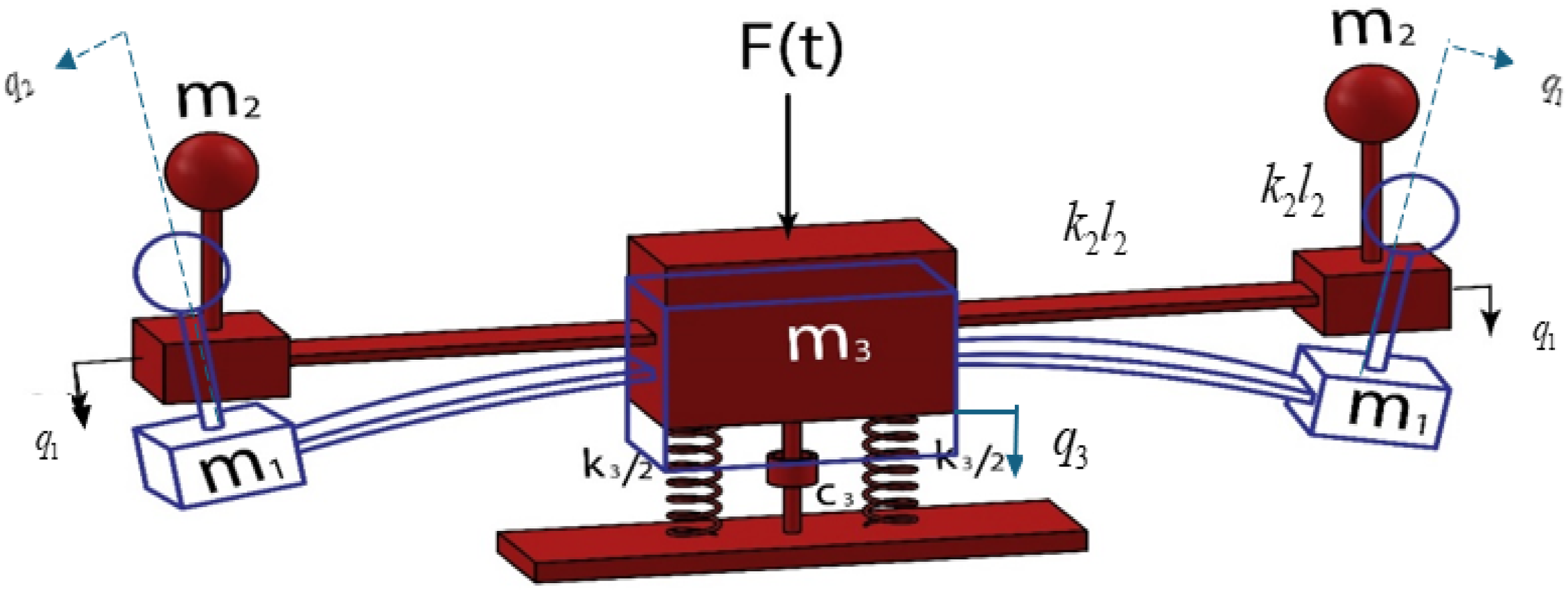
The mechanical system illustrated in Figure 1 represents a nonlinear, coupled, three-degree-of-freedom vibration model designed to capture the interaction between translational and rotational motions. It consists of two identical side branches and a central mass block interconnected through linear springs and damping elements and is subjected to an external excitation force. The configuration combines pendulum-like oscillators with translational masses, introducing strong nonlinear coupling effects and enabling rich dynamic behavior. This type of system serves as a representative model for studying vibration suppression, energy transfer, and nonlinear control strategies in advanced mechanical and electromechanical structures.
The dynamic framework.
Here is a thorough explanation and analysis of the model:
1. Parts of the system
• : vertical motion-related translational mass (left and right).
• : each end of a rotating or pendulum mass (such as a rigid rod or an inverted pendulum).
• : the central mass can move vertically and is susceptible to an external force ().
• Two springs are joined to the ground and symmetrically coupled to mass on the left and right sides.
• A damper is positioned in the center beneath mass and is likewise attached to the earth.
• Two strong elastic connectors that resemble beams and lengths and are connecting the side masses to the central mass.
• : Displacement of the base of the left pendulum (translation).
• : Angle of rotation of the left pendulum.
• : Vertical displacement of the central mass .
• : Time-dependent force applied vertically on the central mass .
2. Performance of the mechanism
• This vibration system has multiple degrees of freedom (MDOF) and is linked.
• The pendulum-equipped lateral arms (masses , ) create complex dynamics, probably including torsional modes, by introducing both translational and rotational motion.
• Because of their stiffness and inertia, the connecting arms react when the central mass is excited by the vertical force .
• Since the system is grounded by a damper and springs, examining its damping and natural frequency responses will be crucial.
2.2. Equation of motion without additional controls
2.3. Equation of motion with additional controls
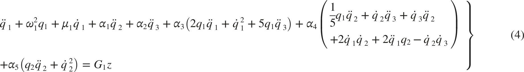
We modified the equation of motion governing the model system from Ref. 46.
Where are linear damping coefficients of the main system and the absorbers, respectively. and are the forcing amplitude and the frequency of the main system. are natural frequencies of the main system and the absorbers, respectively. , , and are linear parameters, otherwise for , , and are nonlinear parameters, and feedback controls.
2.4. Perturbation study (analytically and numerically)
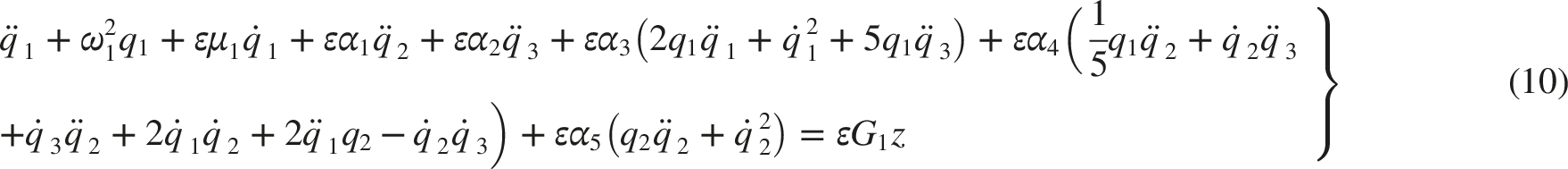
A uniform first-order expansion for the solutions of (4)–(9) is found using the method of multiple scales,47,48 where the equations can be rewritten as follows:
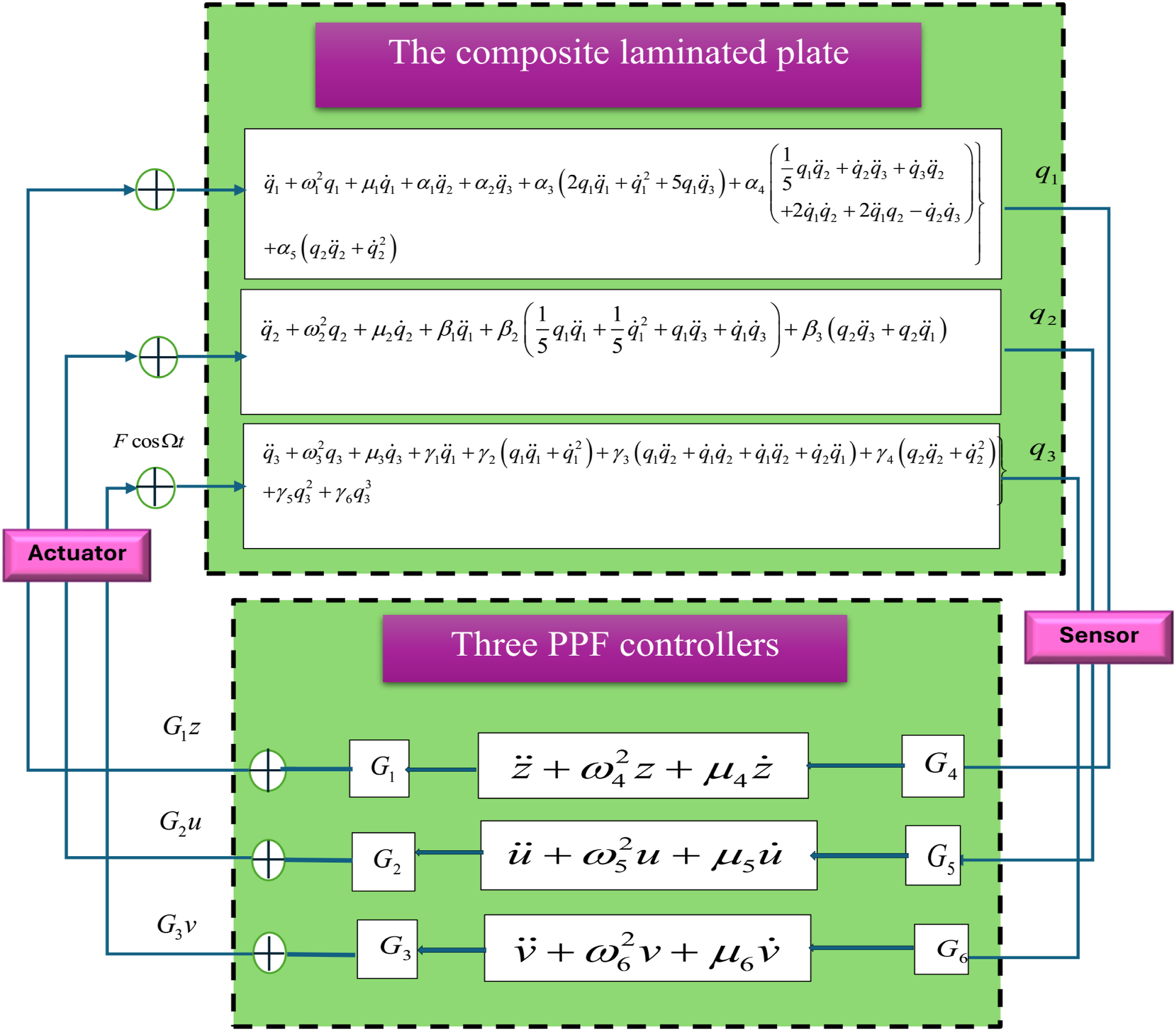
Figure 2 explains the mechanism’s six degrees of freedom with the suggested PPF control. It is helpful to assume the approximate solutions of Eqs. (10)–(15) as follows using the multiple scale procedure:
Where, ε is a small perturbation parameter applied as bookkeeping only, and , are parameters which express the fast and slow timescales. In terms of and , the time derivatives
The block diagram of the new proposed control.
Can be written applying chain rules like:
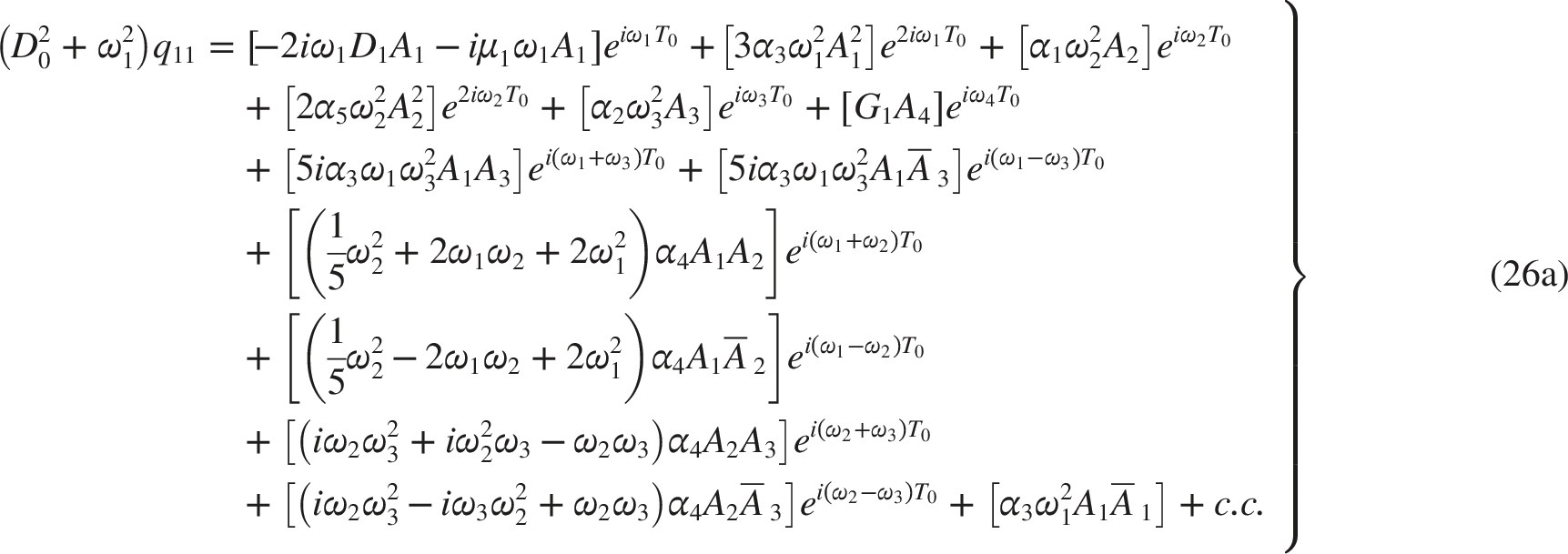
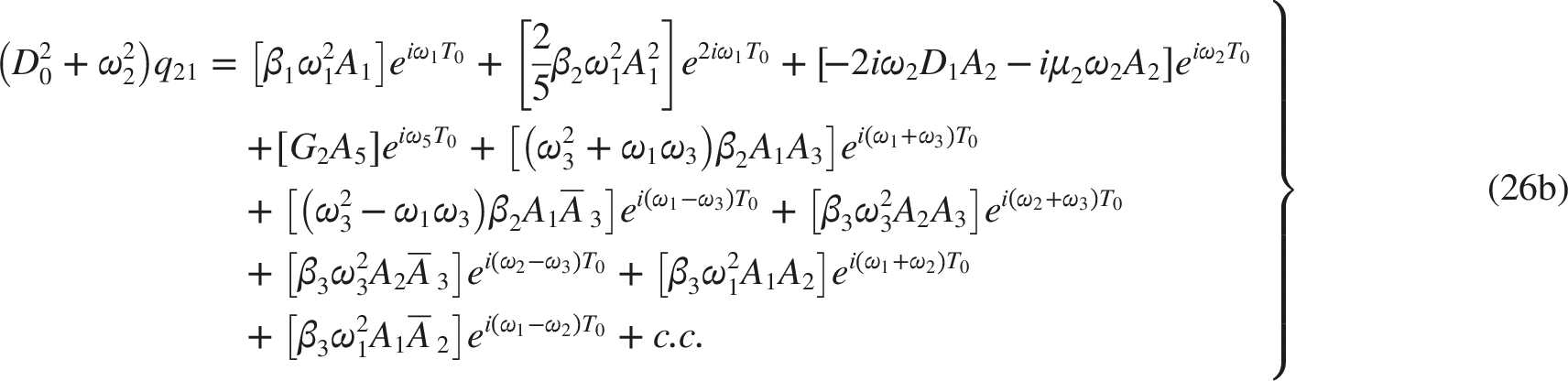
The following set of differential equations is obtained by substituting Eqs. (22a) and (22b) into Eqs. (14)–(17). Then, comparing coefficients that are roughly equivalent to the power of :
where, the coefficients are uncertain functions of , is an imaginary number, and symbolizes the complex conjugate of both of those terms.
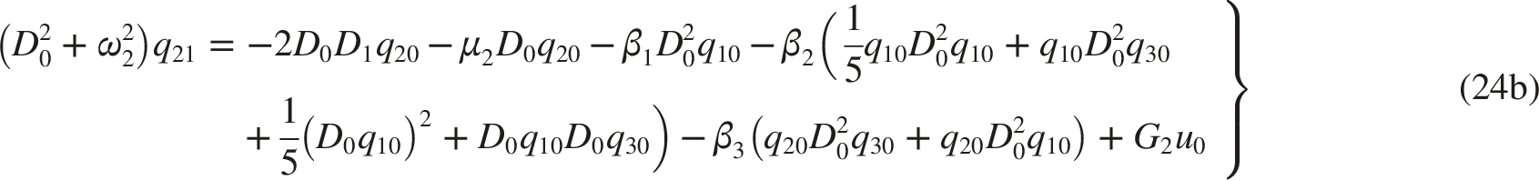
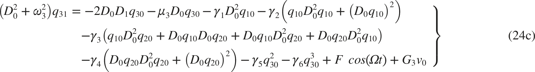
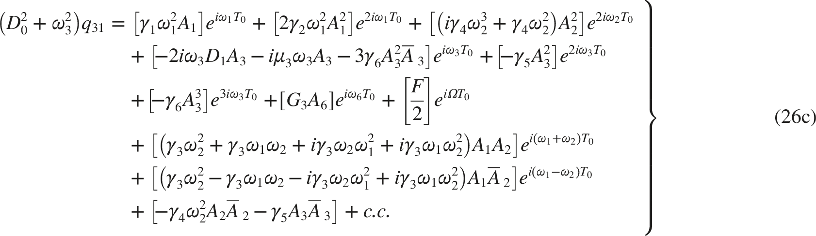
When Eqs. (25a-25f) are swapped into Eqs. (24a-24f), the answer already given is contracted as follows:
We concentrated on the system’s more significant and poorer resonance situations in this investigation. The key resonance cases that have the most important and poorest resonance are
2.5. A numerical representation of time history
To select the optimal control, several control types (Active and Passive control) as PPF, were applied to the nonlinear dynamical system, as stated by Eqs. (10)–(15), are numerically simulated using the MATLAB® computer program. Making use of the Figs’ time history.
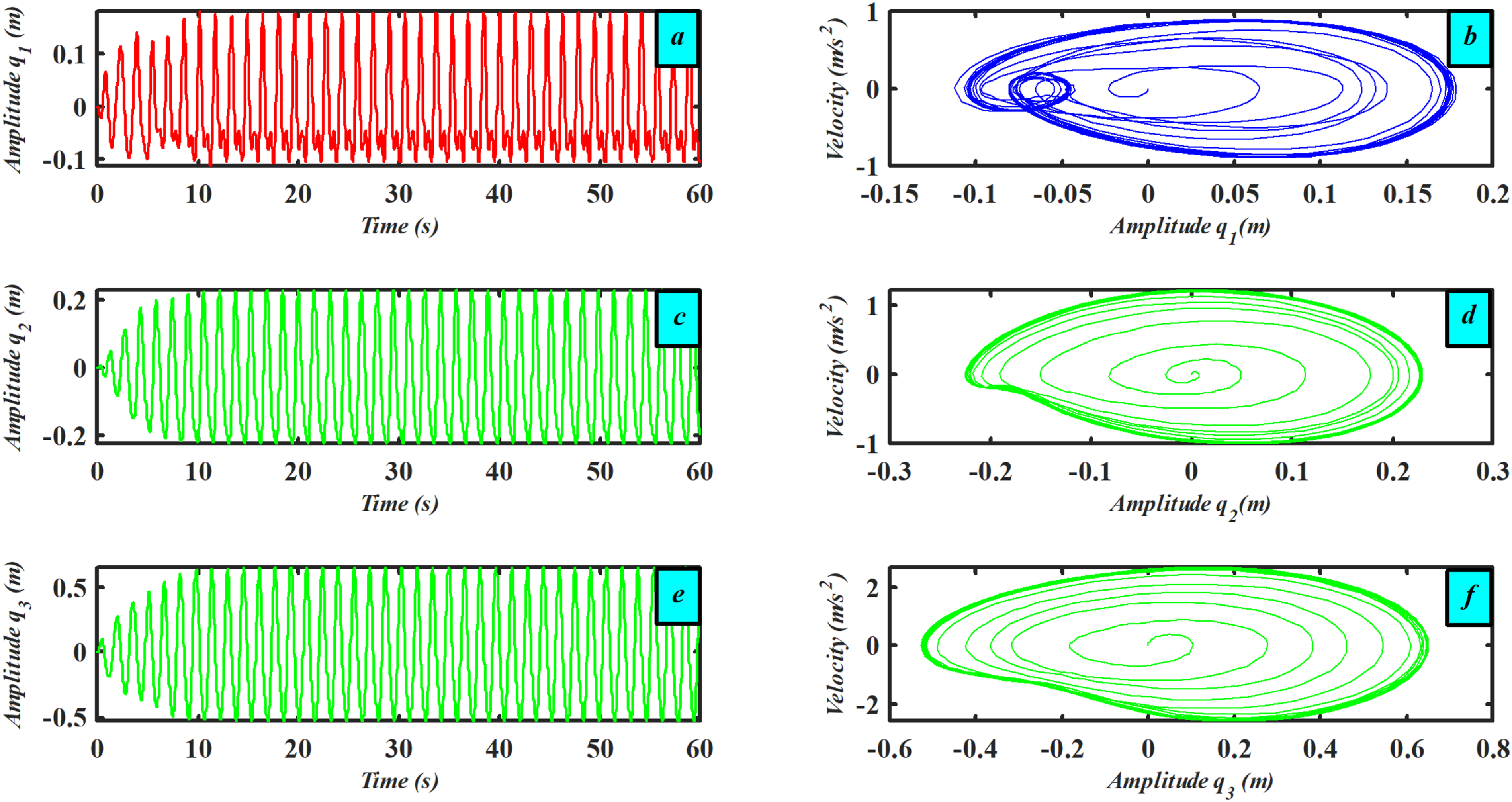
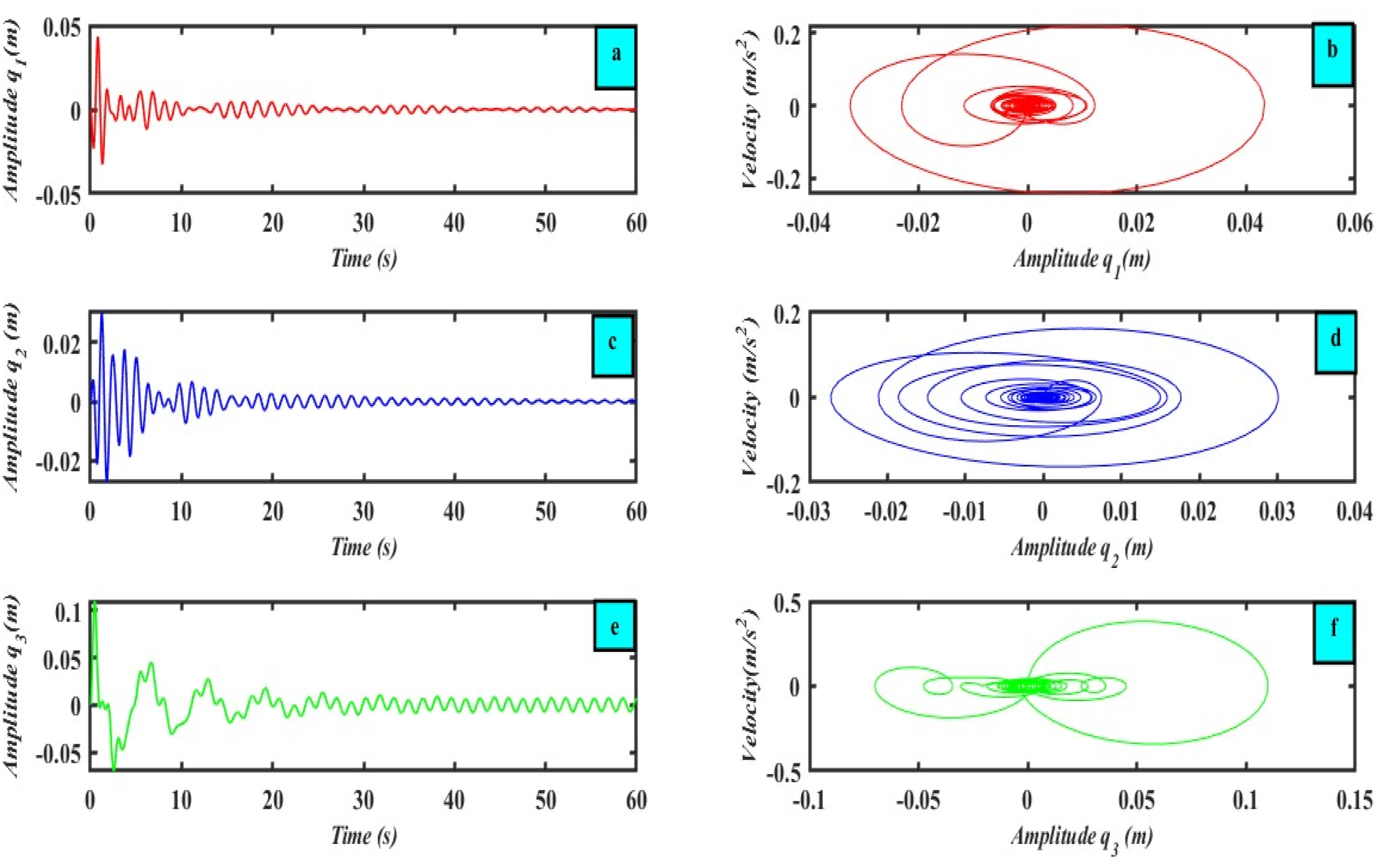
, with initial conditions .The essential system’s steady-state amplitudes () and () are highlighted in Figure 3(a)–(f) just before the primary and 1:1 internal resonance being controlled. The vibration amplitudes for the basic system are plotted in Figure 4, following the use of PPF controllers, reaching 1.275e-06 for with rate 99.99%, and 4.1524e-09 for with rate 99.99%, and 0.000119 for with a rate of 99.98% which happens at time t=14.1736 sec. This indicates that the absorbers’ efficacy ( = steady state amplitude of the main system without absorbers/steady state amplitude of the main system with absorbers) is 5455.88235 for the main system .
Time history responses (a, c, e) for the three parts of the system , and and corresponding phase portraits (b, d, f) for the three parts respectively.
Time history responses (a, c, e) for the three parts of the system , and and corresponding phase portraits (b, d, f) for the three parts, respectively, for the system after applying the PPF control.
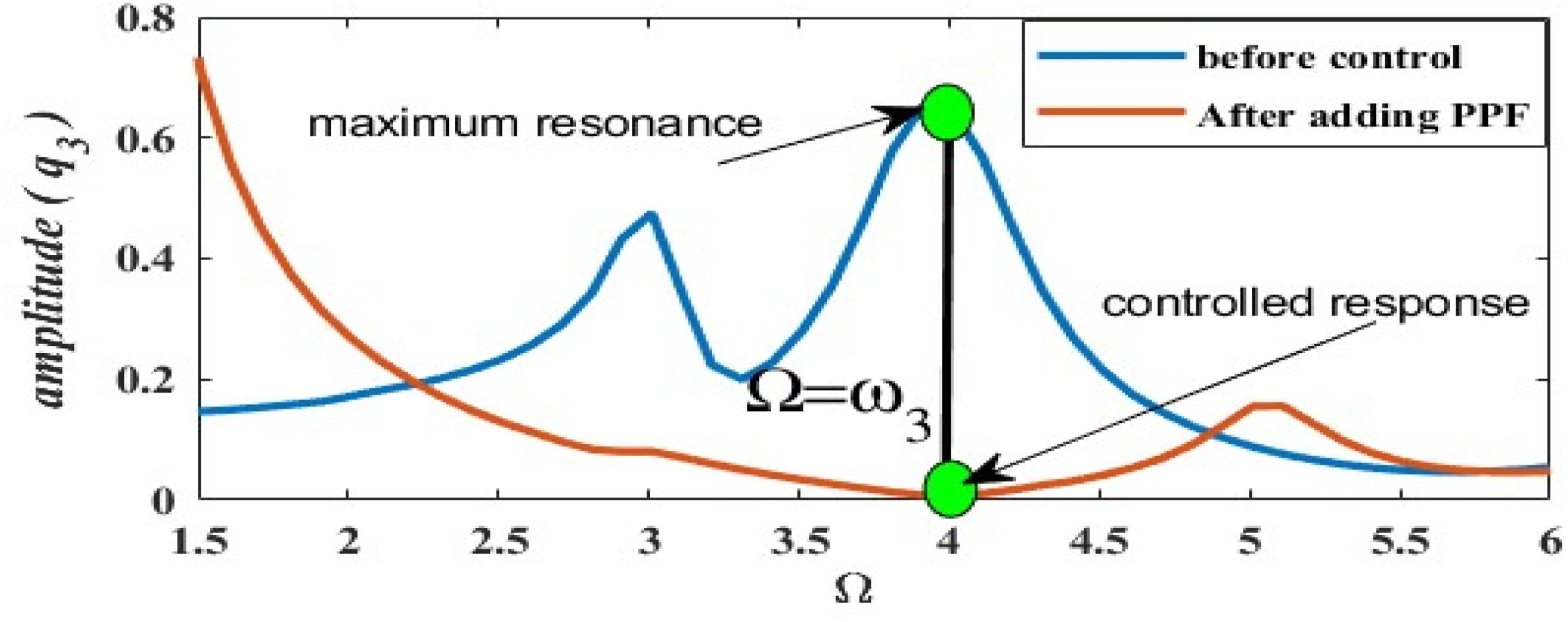
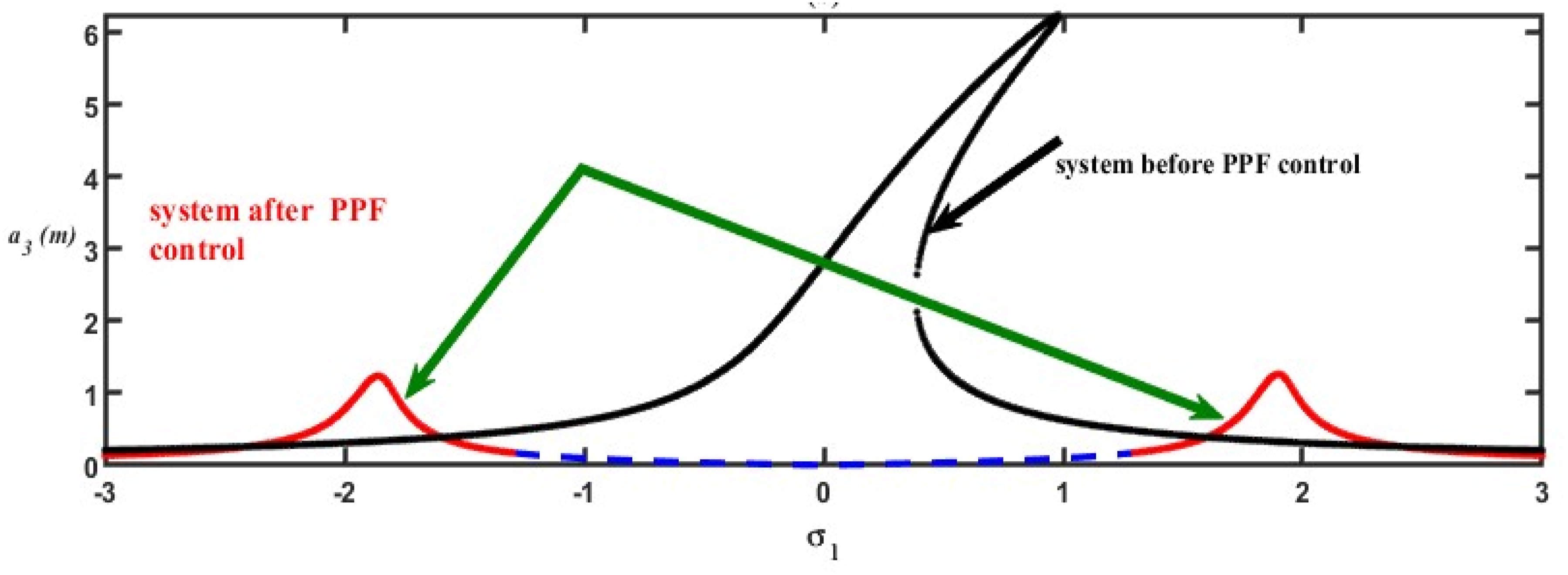
Figure 5 clearly demonstrates the effectiveness of the proposed control strategy at the resonance frequency (). Before applying the controller (blue curve), the system exhibits a sharp resonance peak with a large amplitude, indicating a critical vibration condition. After adding the PPF controller (red curve), the amplitude at the same frequency is significantly suppressed, as highlighted by the markers. This confirms that was chosen because it represents the most severe resonance case, and the figure provides clear evidence of the controller’s ability to reduce vibrations at this critical point.
Comparison of the system response before and after adding the PPF defining the used resonance case.
3. Analytical investigation with stability
Six distinct primary resonance examples will be examined in this study, and they are
These resonance cases will be inserted in the secular terms to obtain;
Rewrite in polar form, we get
where represent the steady-state amplitudes, are motion’s phase angles. Replace Equation (28) with Equations (27a-27f) and then extract the imaginary and real components from the resulting equations. Then, proceed to the modulating equations for the amplitude-phase.
Where
After that, substitute Eqs. (30a-30b) into Eqs. (29a-29l), we attain
3.1. The equations for frequency response (FRE)
At , The steady-state analysis of the model with PPF controllers is finished, and it matches the fixed point of Eqs. (29a, 29c, 29e, 29g, 29i, 29j) and (31a–31f). The effective case’s frequency response equations can therefore be obtained as follows:
3.2. Algorithms for frequency response at optimal solution
Equations that describe the initial frequency response equations (FRE) can be obtained by doubling equations (32e), (32f), and (32k), (32l) and then adding them together into another.
We will concentrate on the case that (, and )
3.3. Analysis of stability at the fixed point
Start using the following procedure to determine the steady-state solution’s stability. Let’s
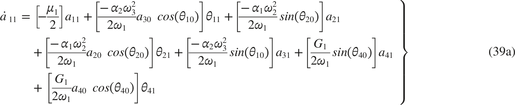
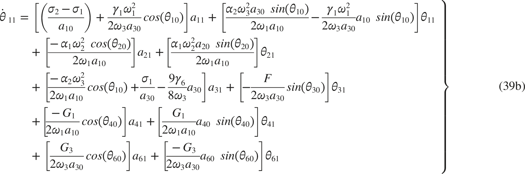
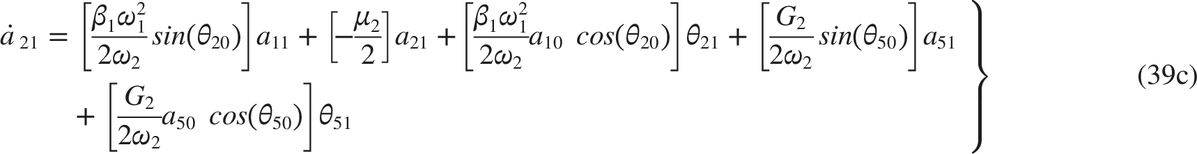
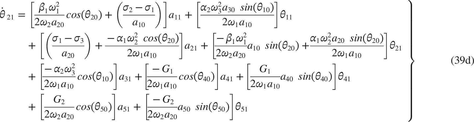
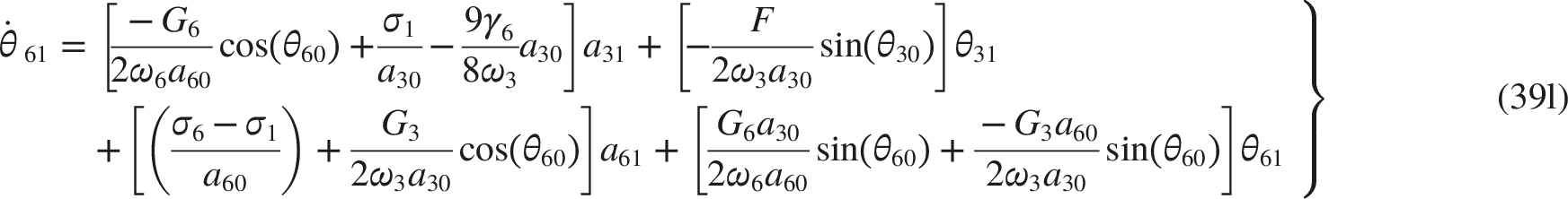
Given that and meet the requirements of equations (29a, 29c, 29e, 29g, 29i, 29j) and equations (31a–31f), is regarded as a minor disturbance in relation to and . Then, using Eqs (38) and just the linear terms and left, we obtain
The above Eqs (39a)–(39l) can be characterized as the matrix outlined below:
where the Jacobin matrix of equations (39a)–(39l) is denoted by . The Jacobin matrix eigenvalues can be expressed as follows:
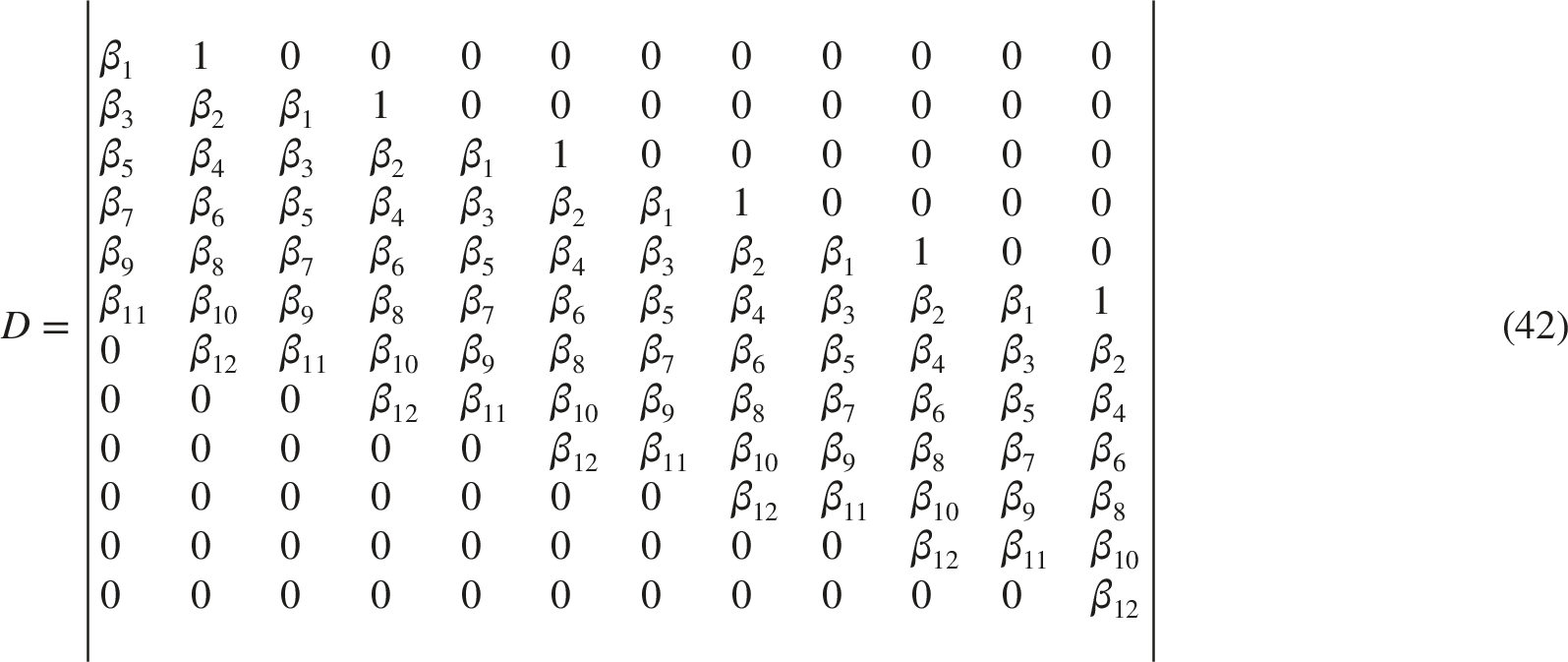
If the eigenvalue’s real component is negative, the solutions are stable; if not, they become unstable. Here , denotes the coefficient found in Equation (41). Every root of Eq. (41) must meet the requirement that the determinant () in (42) and all of its principal minors be positive in accordance with the Routh-Hurwitz criterion. Stability will only be guaranteed when Eq. (41) produces negative real portions.
4. Results and discussion
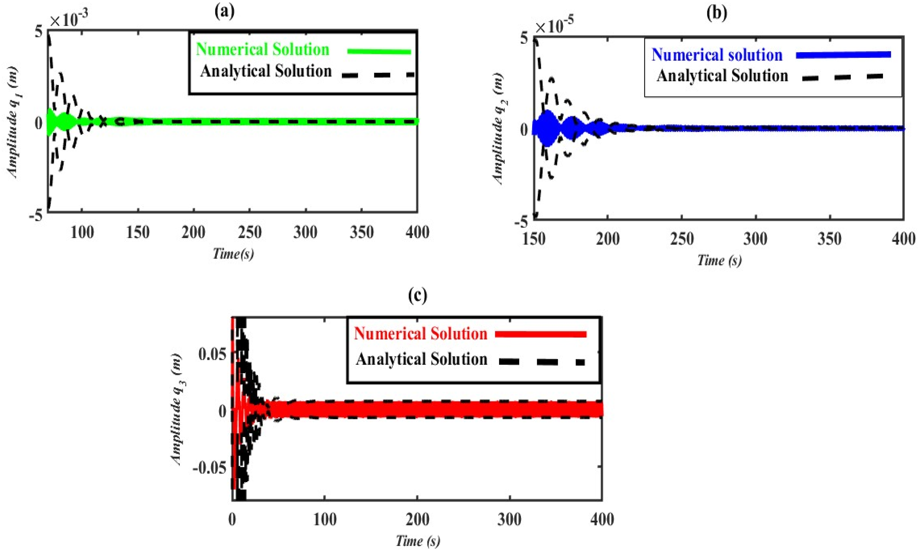
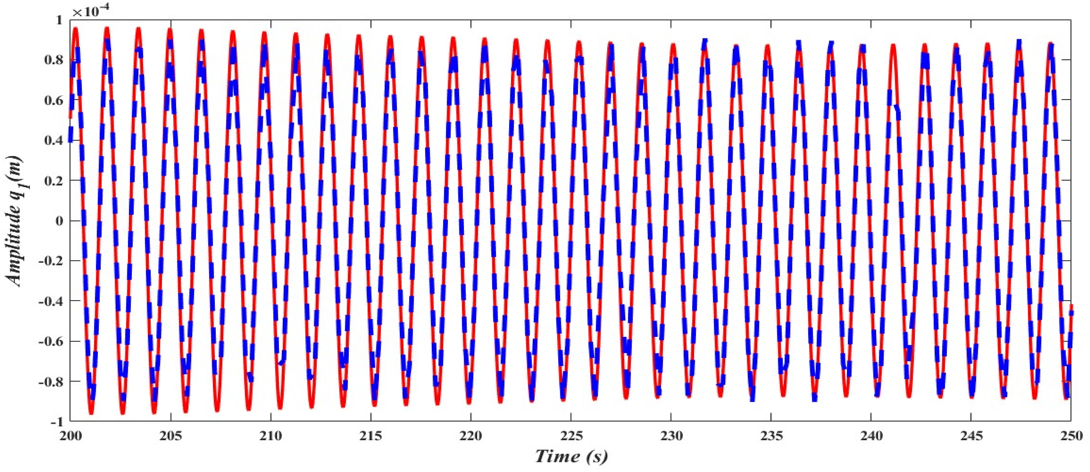
The perturbation analysis of Eqs. (29a, 29c, 29e, 29g, 29i, 29j) and (31a–31f) is first graphically verified in this section through the numerical simulation of Eqs. (10) and (15), as illustrated in Figure 3. The comparison was set up at primary and 1:1 internal resonance at (i.e., ) using the same values selected for the PPF control and observed system parameters as those used in the Figure 6(a)–(c). The amplitude modulations , and for the generalized coordinates and are shown by the dashed lines. On the other hand, the linked lines show the vibrations’ temporal history, which was numerically simulated as the system’s PPF-controlled solutions.
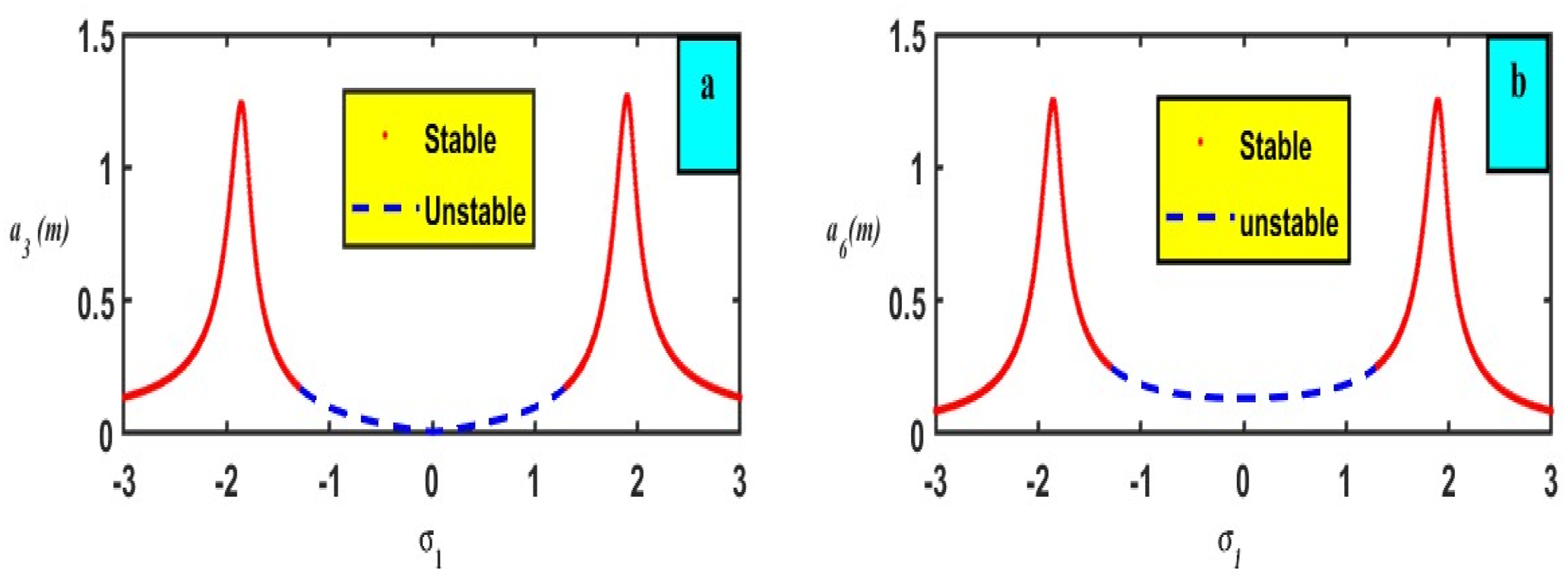
A contrast of numerical simulation and perturbation analysis for the three parts of the system , and .
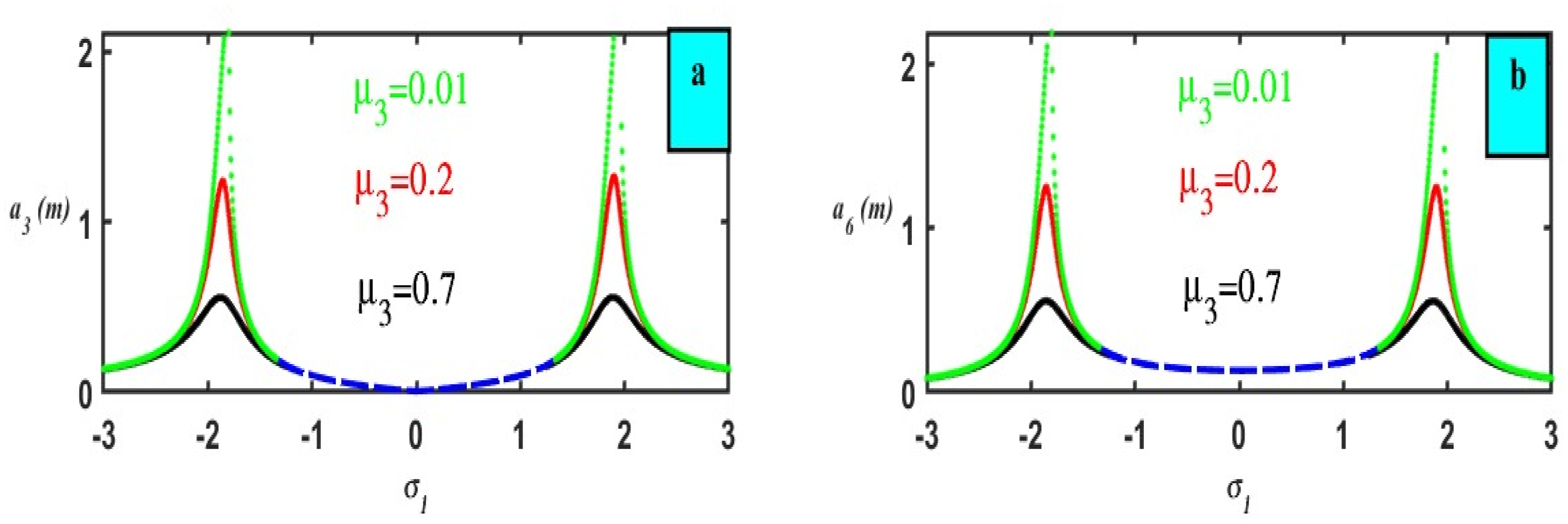
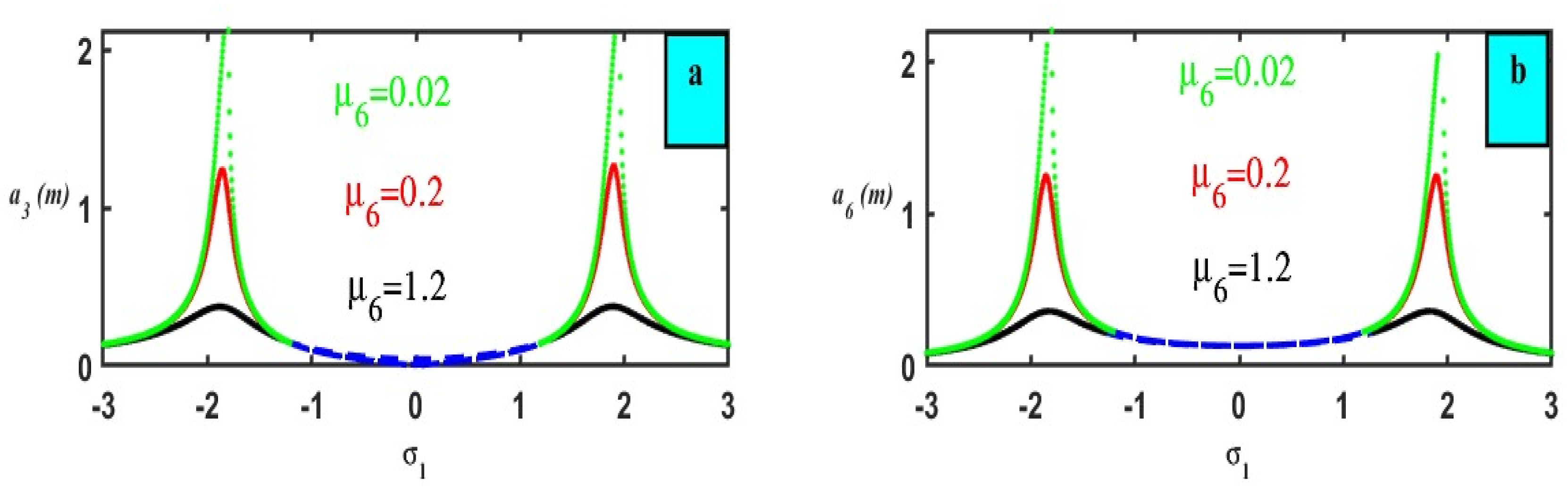
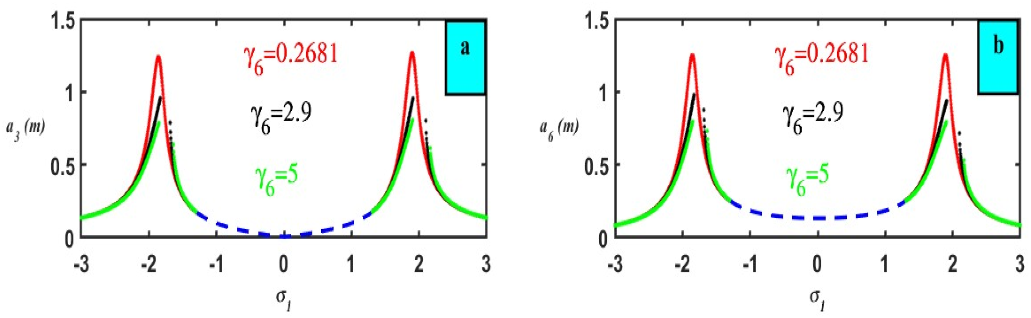
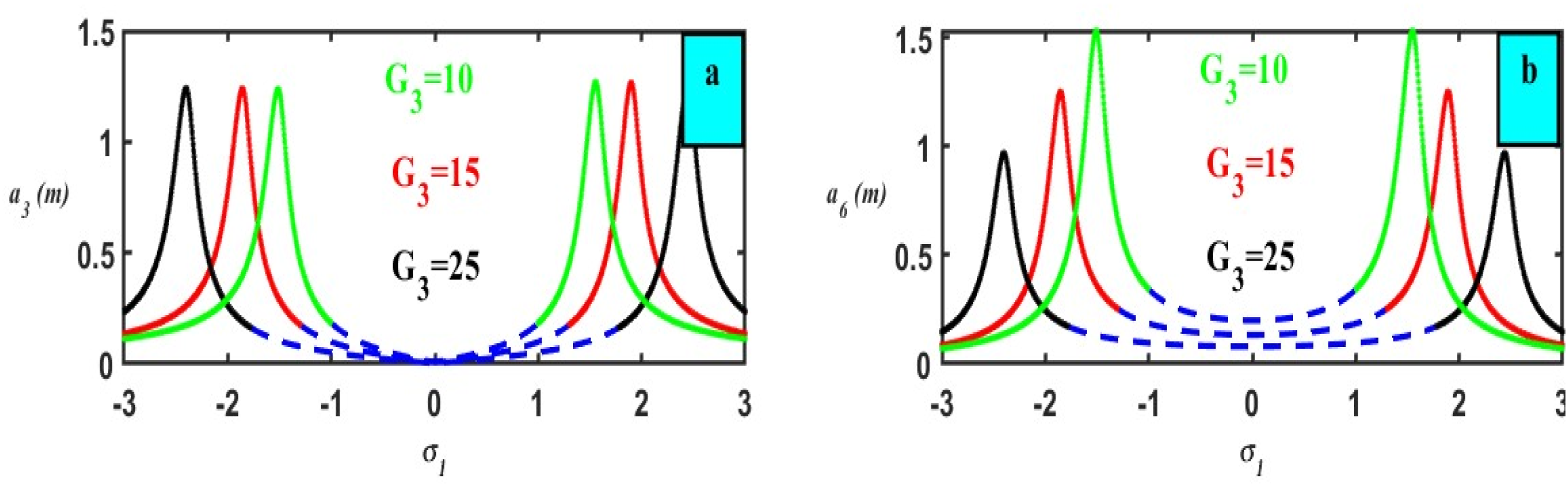
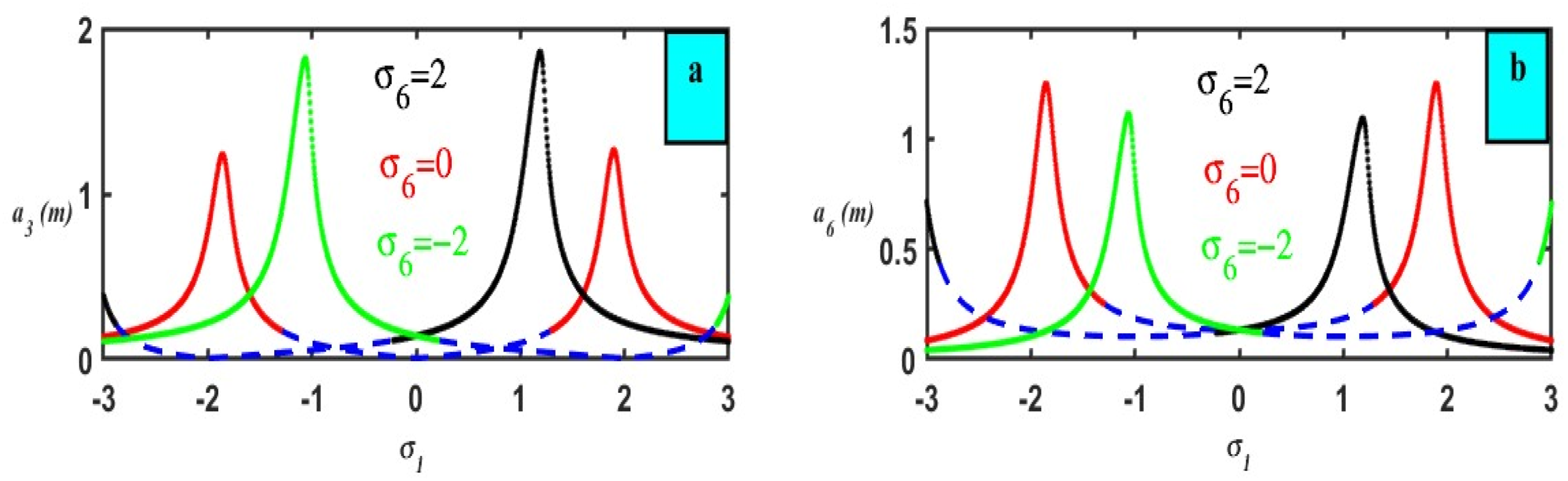
The frequency-modulation behavior of and vs following the addition of PPF control is shown in Figure 7(a) and (b). We found out that the steady-state amplitude’s modest value occurred at , confirming that the PPF control effectively lowers the recorded resonance vibration. The dotted blue lines show the erratic solution, and the joined red lines show the stable solution. The significant system and PPF steady-state amplitudes increase when the excitation force amplitude grows, as demonstrated by Figure 8(a) and (b). Another benefit is that it is evident from Figure 9(a) and (b) that the bandwidth of vibration increased with the amplitude of the entire structure and controller as the natural frequencies diminished. The system and controller behavior cut down, and the bandwidth of the peak amplitude is gradually eliminated as the nonlinear components , , and have grown as is apparent in Figures 10 and 11, and 12(a) and (b). The primary system’s peak amplitudes for the gain are equal in Figure 13(a) with the main system , when the gain value rises, the dip between the peaks widens. As the gain values lowered, the beaks expanded, and the dips between them diminished, as shown in the other portion of Figure 13(b), PPF control. Otherwise, for the gain ,as its values lowered, the beaks expanded and the dips between them diminished, as shown in Figure 14(a), but for the control, the amplitude is decreased as the value of is decreased and that appears in Figure 14(b). The response of the detuning parameter on the controller and system are displayed in Figure 15(a) and (b). The bandwidth peak amplitude shifts to the right for increasing values of , and the system and controller amplitude is at its lowest at
Frequency-response curves (FRC) of: (a) The fundamental mechanism (b) PPF controller .
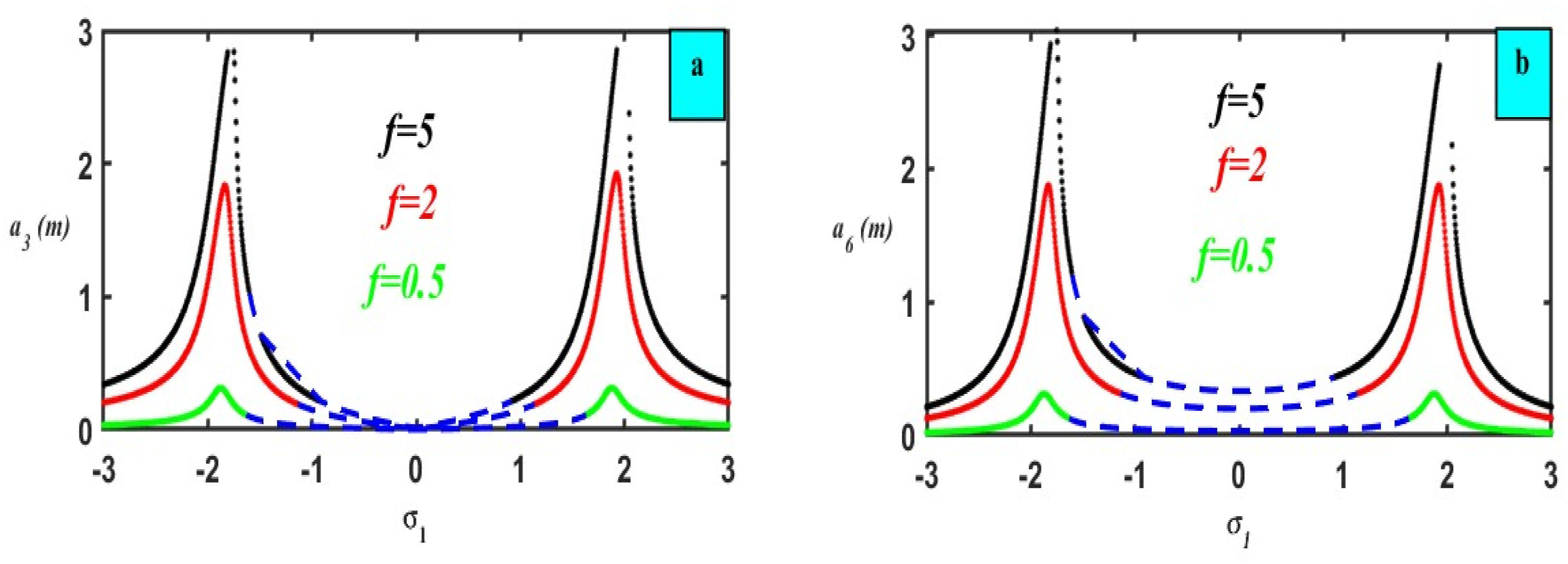
The impact of an outside force (a) on the fundamental mechanism (b) on the control .
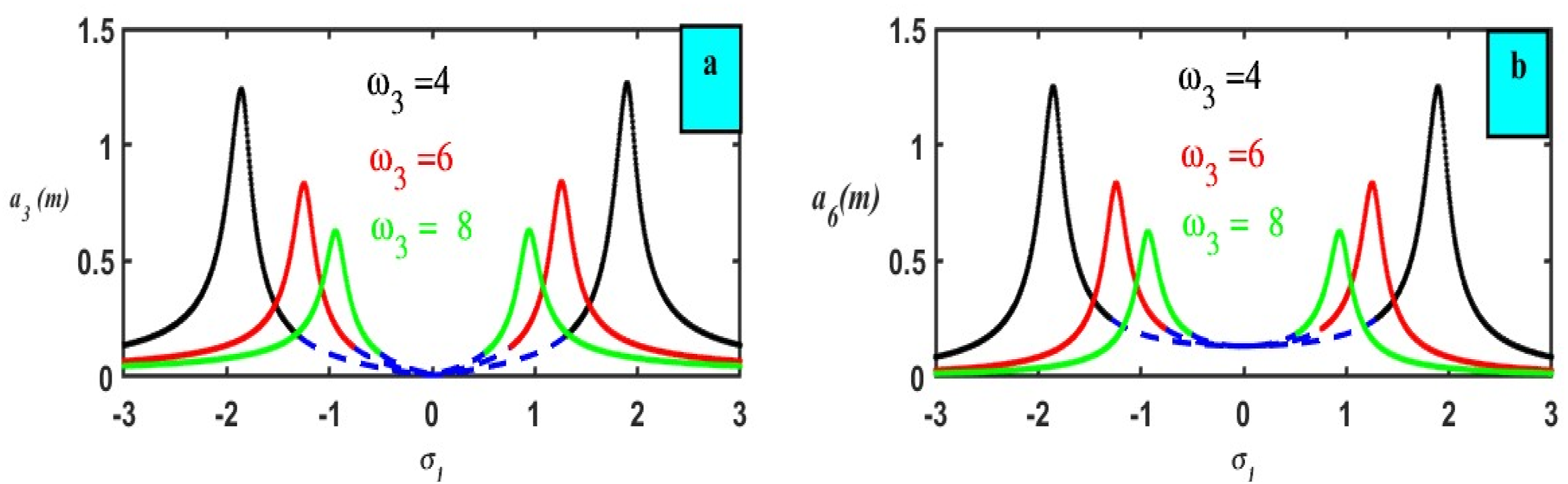
The impact of the nature frequency (a) on the fundamental mechanism (b) on the control .
The impact of the nonlinear parameter (a) on the fundamental mechanism (b) on the control .
The impact of the nonlinear parameter (a) on the fundamental mechanism (b) on the control .
The impact of the nonlinear parameter (a) on the fundamental mechanism (b) on the control .
The impact of the gain (a) on the fundamental mechanism (b) on the control .
The impact of the gain (a) on the fundamental mechanism (b) on the control .
The impact of the detuning parameter (a) on the fundamental mechanism (b) on the control .
5. Affirmation between FRC and RK-4 study
Figure 16(a) and (b) give comparisons between before and after adding different controls. The plot 16(a) shows that while the uncontrolled system (red) exhibits large, sustained oscillations, passive control (green) significantly reduces the amplitude, and PPF control (black) provides the most effective vibration suppression with minimal residual oscillations, demonstrating superior damping performance over 200 . Figure 16(b) compares the vibration response of the system under three different control strategies: Passive control (green), NSC (magenta), and PPF control (black). It is evident that the passive control exhibits the largest oscillation amplitude, with a sustained vibration level of approximately ±0.3 , indicating weak suppression efficiency. The NSC shows improved performance by reducing the oscillation amplitude to about ±0.1 ; however, it still maintains visible residual vibrations. In contrast, the PPF control demonstrates the best performance, as it rapidly suppresses the vibrations and stabilizes the response around zero with minimal residual oscillations. This highlights the superior damping capability of the PPF controller compared to both passive control and NSC. Furthermore, in Figure 17 we plot the FRC curves before and after PPF. This analysis leads us to confirm the efficiency of the PPF control quite well.
(a) Mechanism operation both prior to and following the addition of a PPF controller. .
Comparison between FRC before and after adding PPF control.
6. Affirmation between FRC and time history
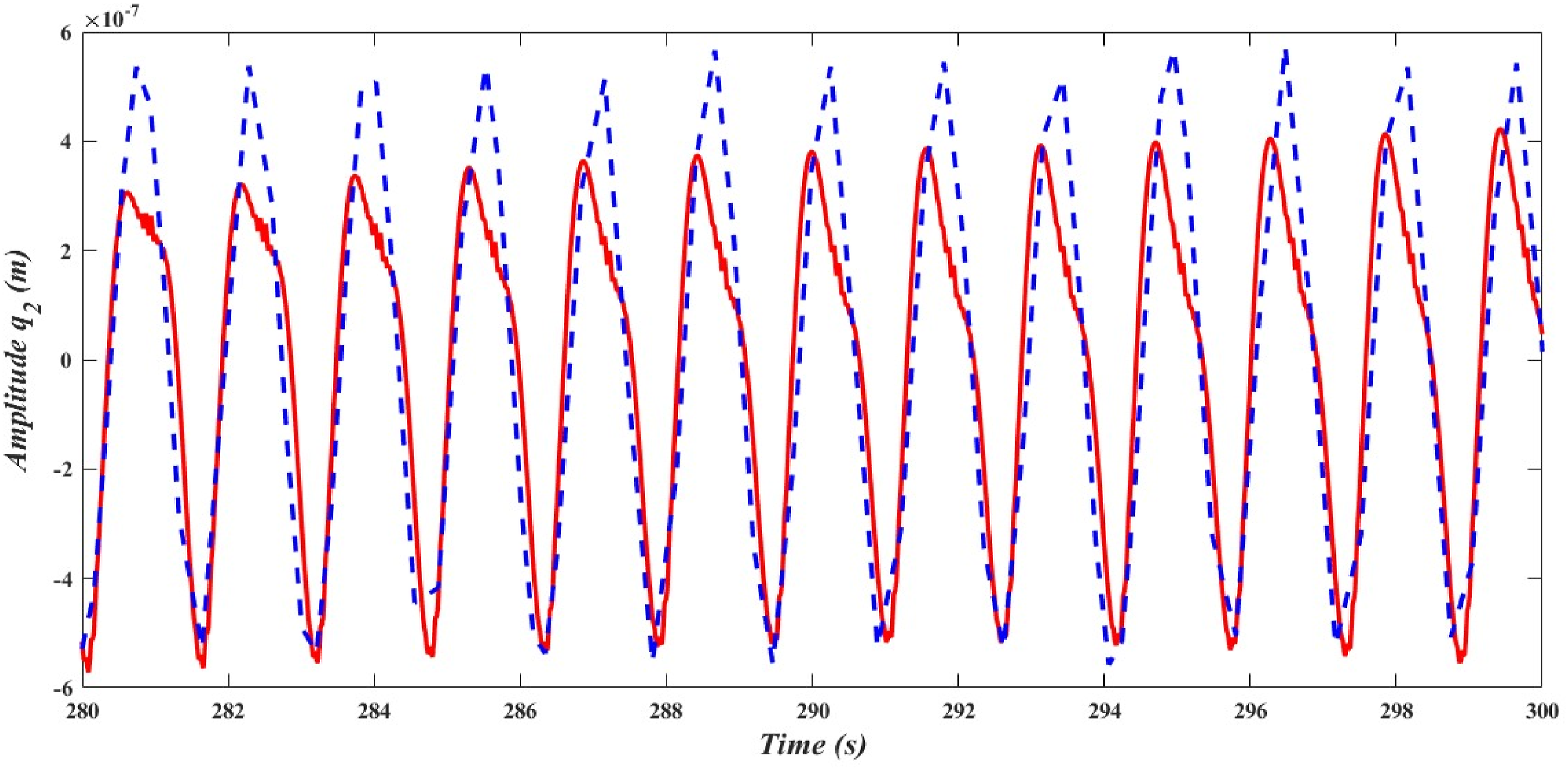
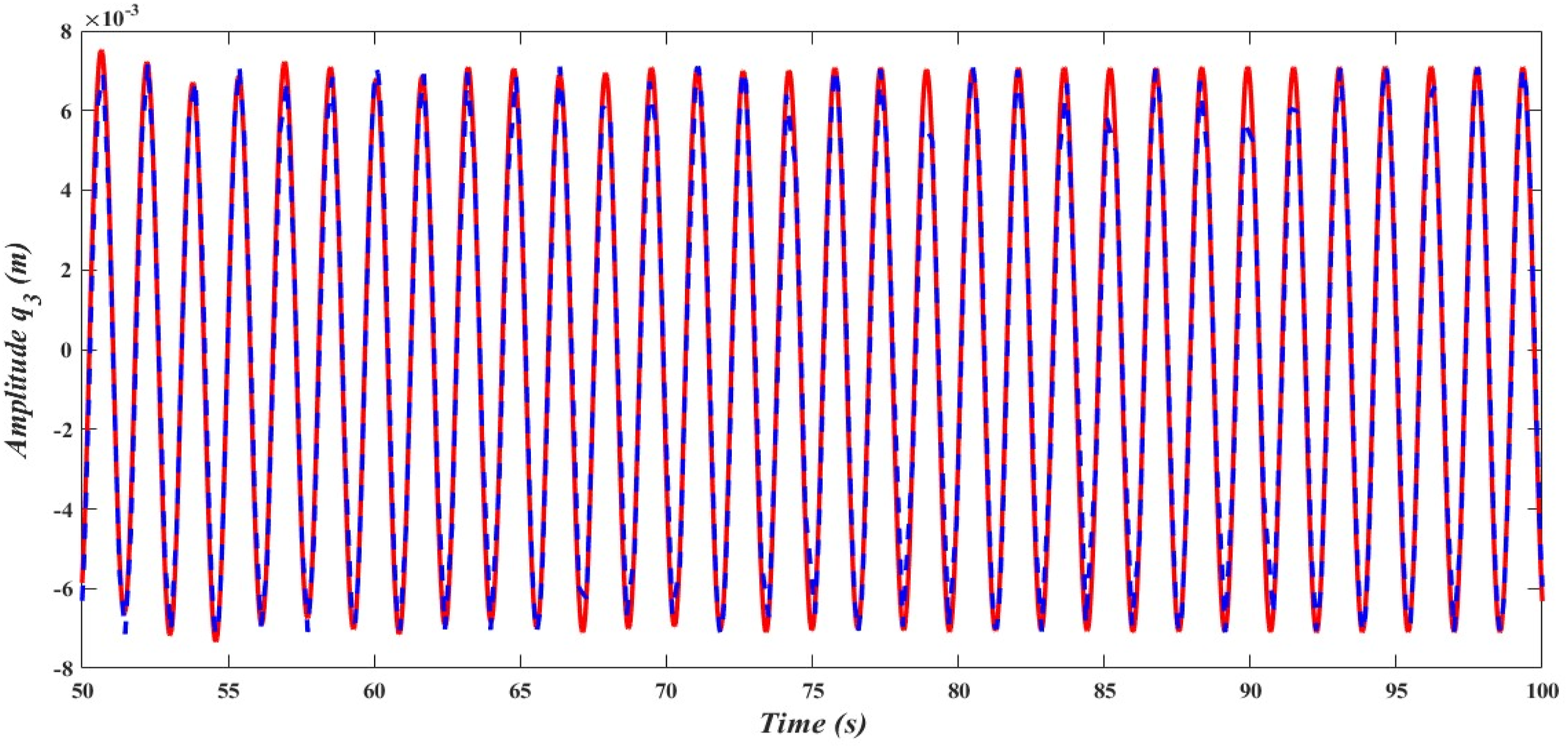
The three figures below present a comparison between the time history responses (blue dashed lines) and the corresponding frequency response reconstructions (red solid lines) for different system coordinates. Overall, the results confirm the effectiveness of the frequency response method in capturing the essential dynamics of the system. Figure 18, studying , the two responses show nearly perfect overlap in both amplitude and phase during the time period , indicating that the frequency response approach accurately reproduces the steady-state oscillations obtained from the time history simulation. Figure 19, illustrating the performance of , while the two responses maintain the same oscillation frequency and general waveform, a slight amplitude discrepancy is observed during the time period ; the frequency response underestimates the peak values compared to the time history. This suggests that certain nonlinear effects or higher-order harmonics are better represented in the time-domain analysis. Figure 20 clarifies the behaviour , a very close match is again observed between the two methods in the interval , with both amplitude and phase in strong agreement. The curves are almost indistinguishable, reinforcing the accuracy of the frequency response formulation.
Comparison of the time history and frequency response of showing excellent agreement.
Time history versus frequency response of , with slight amplitude deviation.
Comparison of time history and frequency response of , showing close overlap.
7. Comparing this work to the already released one
1. To lessen the vibration of the system under study close to a simultaneous resonance case, Ref. 46 used active control based on negative acceleration feedback, taking the case ().
2. In this piece
• To bring down the vibration noticed in the present experiment, we combined three separate controllers (PPF) and changed the equation provided in Ref. 46.
• The mathematical result and all resonance situations are derived using the multiple time scales method (MTSM).
• After attaching the PPF controller, stability and the numerical solution are investigated at .
• Without the need for an additional controller, the PPF controller effectively reduces the primary system’s amplitude to around 99.98% of its original value.
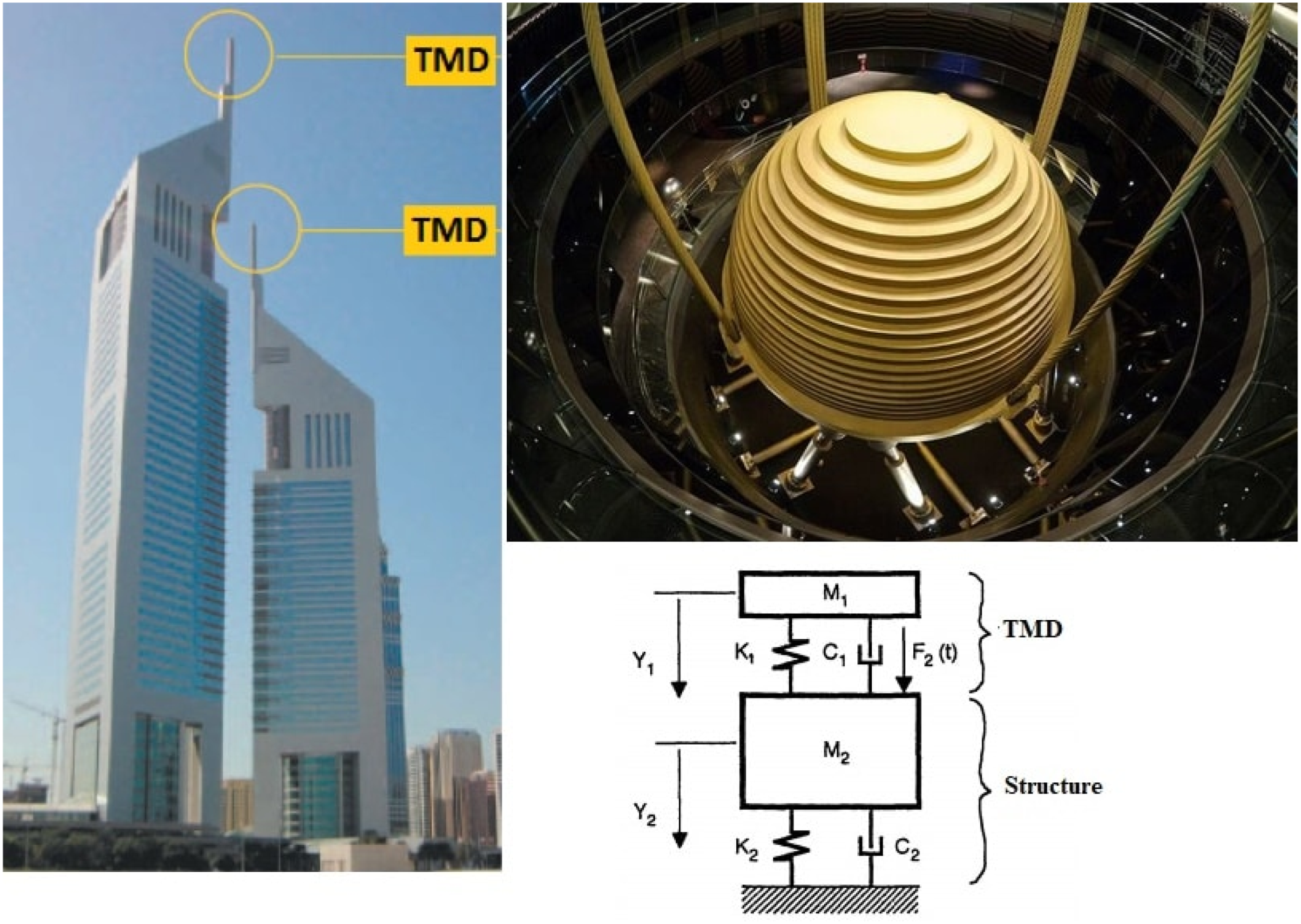
8. Implementation of the system in the applications
This configuration is similar to those found in Figure 21 as follows:
• Tuned mass dampers (TMD) or vibration absorbers are used for alleviating resonance in building components.
• Suspension systems are used in automobiles or aircraft, where the wheels and body of the vehicle are modeled by the central and side masses.
• This study investigates the nonlinear interaction of a structural framework with six degrees of freedom (DOF), focusing on the system’s behavior under external excitation and the influence of internal resonances.
• The multiple time scales perturbation method (MSPM) is applied to derive analytical solutions and resonance conditions.
• A positive position feedback (PPF) controller is introduced to mitigate vibrations. The controlled model increases to six DOFs after incorporating the controller dynamics.
• Analytical results are validated using MATLAB simulations (ode45), demonstrating strong agreement between numerical and analytical solutions.
• Frequency response curves (FRCs) are analyzed to identify stable and unstable zones, and the PPF controller shows a 99.98% vibration reduction rate (from 0.64925 to 0.000119).
• The findings confirm that the PPF controller is highly effective near resonance conditions, and the averaging strategy accurately predicts system performance.
• Overall, this work contributes novel modeling and control insights for vibration mitigation in nonlinear multi-DOF systems, providing a validated approach with potential engineering applications.
Footnotes
ORCID iDs
Fatma Taha EL-Bahrawy
Rageh K. Hussein
Ashraf Taha EL-Sayed
Author contributions
F. T. E.: Formal analysis, validation, investigation, methodology, data curation, conceptualization, validation, writing—review and editing. R. K. H.: Investigation, Methodology, Formal Analysis, reviewing and editing, and funding acquisition. A.T. E.: Conceptualization, resources, methodology, writing- original draft preparation, visualization, reviewing, and editing. All authors have read and agreed to the published version of the manuscript.
Funding
This work was supported and funded by the Deanship of Scientific Research at Imam Mohammad Ibn Saud Islamic University (IMSIU) (grant number IMSIU-DDRSP2603).
Declaration of conflicting interests
The authors declared no potential conflicts of interest with respect to the research, authorship, and/or publication of this article.
Data Availability Statement
All data generated or analyzed during this study are included in this published article.*
Appendix
In the analysis of the system shown, only the symmetric motions of the system, considering both sides of the model, are considered. Under external excitation, the system response will be described by the generalized coordinates and as shown in Figure 1. The equations of motion are derived by applying Lagrange’s equations;
Where The kinetic energy is given by the expression
where a dot denotes differentiation with respect to time . With the gravitational effects neglected, the potential energy is given by the elastic energy
Substituting from and n equation (1) and bypassing energy dissipation due to damping (damping forces will be introduced latter) yields the equations of motion
KiperGSoylemezE. Deployable space structures. In: 2009 4th International Conference on Recent Advances in Space Technologies, IEEE, Istanbul, Turkey, 2009, pp. 131–138. https://doi.org/10.1109/RAST.2009.5158183
2.
SharmaAKumarRVaishR, et al.Active vibration control of space antenna reflector over wide temperature range. Composite Structures2015; 128: 291–304. https://doi.org/10.1016/j.compstruct.2015.03.062
3.
DavisLPCunninghamDBicosAS, et al.Adaptable passive viscous damper: an adaptable D-StrutTM. Proc. SPIE 2193, Smart Structures and Materials 1994: Passive Damping1994; 2193: 47–59. https://doi.org/10.1117/12.174114
4.
LeeYYSuRKLNgCF, et al.The Effect of Modal Energy Transfer on the Sound Radiation and Vibration of a Curved Panel: Theory and Experiment. J. Sound Vib2009; 324: 1003–1015. https://doi.org/10.1016/j.jsv.2009.02.042
5.
TussetAMBalthazarJMChavaretteFR, et al.On Energy Transfer Phenomena, in a Nonlinear Ideal and Nonideal Essential Vibrating Systems, Coupled to a (MR) Magneto Rheological Damper. Nonlinear Dyn2012; 69: 1859–1880. https://doi.org/10.1007/s11071-012-0391-5
6.
KurtMEritenMMcFarlandDM, et al.Strongly nonlinear beats in the dynamics of an elastic system with a strong local stiffness nonlinearity: Analysis and identification. J. Sound Vib2014; 333: 2054–2072. https://doi.org/10.1016/j.jsv.2013.11.021
7.
KurtMEritenMMcFarlandDM, et al.Frequency–energy plots of steady-state solutions for forced and damped systems, and vibration isolation by nonlinear mode localization. Commun. Nonlinear Sci. Numer. Simul2014; 19: 2905–2917. https://doi.org/10.1016/j.cnsns.2013.12.018
8.
KurtMSlavkinIEritenM, et al.Effect of 1:3 resonance on the steady-state dynamics of a forced strongly nonlinear oscillator with a linear light attachment. Arch. Appl. Mech2014; 84: 1189–1203. https://doi.org/10.1007/s00419-014-0877-3
9.
KurtM. Identification Reduced Order Modeling and Model Updating of Nonlinear Mechanical Systems. Ph.D. Thesis. University of Illinois at Urbana-Champaign, 2014.
JaliliNKnowlesDWIV. Structural vibration control using an active resonator absorber: Modeling and control implementation. Smart Mater. Struct2004; 13, 998–1005. https://doi.org/10.1088/0964-1726/13/5/004
12.
ViguieRKerschenG. Nonlinear vibration absorber coupled to a nonlinear primary system: A tuning methodology. J. Sound Vib2009; 326: 780–793. https://doi.org/10.1016/j.jsv.2009.05.023
13.
CasciatiFRodellarJYildirimU. Active and semi-active control of structures-theory and applications: A review of recent advances. J. Intell. Mater. Syst. Struct2012; 23: 1181–1195. https://doi.org/10.1177/1045389X12445029
14.
ZhangHWangRRWangJM, et al.Robust finite frequency H-∞ static-output-feedback control with application to vibration active control of structural systems. Mechatronics2014; 24: 354–366. https://doi.org/10.1016/j.mechatronics.2013.07.013
LiuJGLiYMZhangY, et al.Dynamics and control of a parallel mechanism for active vibration isolation in space station. Nonlinear Dyn2014; 76: 1737–1751. https://doi.org/10.1007/s11071-014-1242-3
17.
GrodsinskyCMWhortonMS. Survey of active vibration isolation systems for microgravity applications. J. Spacecr. Rocket2000; 37: 586–596. https://doi.org/10.2514/2.3631
18.
MehendaleCSFialhoIJGrigoriadisKM. A linear parameter-varying framework for adaptive active microgravity isolation. J. Vib. Control2009; 15: 773–800. https://doi.org/10.1177/1077546308091459
19.
AmerTSEl-SabaaFMZakriaSK, et al.The stability of 3-DOF triple-rigid-body pendulum system near resonances. Nonlinear Dyn2022; 110: 1339–1371. https://doi.org/10.1007/s11071-022-07722-x
20.
AmerTSBekMAHassanSS. The dynamical analysis for the motion of a harmonically two degrees of freedom damped spring pendulum in an elliptic trajectory. Alex Eng J2022; 61(2): 1715–1733. https://doi.org/10.1016/j.aej.2021.06.063
21.
ThayerDCampbellMVagnersJ, et al.Six-Axis Vibration Isolation System Using Soft Actuators and Multiple Sensors. Journal of Spacecraft and Rockets2002; 39(2): 206–212. https://doi.org/10.2514/2.3821
22.
LiuCJingXDaleyS, et al.Recent advances in micro-vibration isolation. Mechanical Systems and Signal Processing2015; 56-57: 55–80. https://doi.org/10.1016/j.ymssp.2014.10.007
23.
ZhangYZangYLiM, et al.Active-passive integrated vibration control for control moment gyros and its application to satellites. Journal of Sound and Vibration2017; 394: 1–14. https://doi.org/10.1016/j.jsv.2017.01.002
24.
YaoZJingruiZShijieX. Parameters design of vibration isolation platform for control moment gyroscopes. Acta Astronautica2012; 81(2): 645–659. https://doi.org/10.1016/j.actaastro.2012.08.031
25.
ZhuTCazzolatoBRobertsonWSP, et al.Vibration isolation using six degree-of-freedom quasi-zero stiffness magnetic levitation. Journal of Sound and Vibration2015; 358: 48–73. https://doi.org/10.1016/j.jsv.2015.07.013
26.
LinZPachterMBandaS. Toward improvement of tracking performance nonlinear feedback for linear systems. International Journal of Control1998; 70(1): 1–11. https://doi.org/10.1080/002071798222433
27.
ChenBMLeeTHPengK, et al.Composite nonlinear feedback control for linear systems with input saturation: theory and an application. IEEE Transactions on Automatic Control2003; 48(3): 427–439. https://doi.org/10.1109/TAC.2003.809148
28.
El-SayedATBauomyHS. Nonlinear analysis of vertical conveyor with positive position feedback (PPF) controllers. Nonlinear Dyn2016; 83: 919–939. https://doi.org/10.1007/s11071-015-2377-6
29.
El-SayedATBauomyHS. Outcome of special vibration controller techniques linked to a cracked beam. Appl. Math. Model2018; 63: 266–287. https://doi.org/10.1016/j.apm.2018.06.045
30.
BauomyHEl-SayedATSalemAM, et al.The improved giant magnetostrictive actuator oscillations via positive position feedback damper. AIMS Mathematics2023; 8(7): 16864–16886. https://doi.org/10.3934/math.2023862
31.
BauomyHSEl-SayedATEl-BahrawyFT. Integral resonant negative derivative feedback suppression control strategy for nonlinear dynamic vibration behavior model. Chaos, Solitons and Fractals2024; 189: 115686. https://doi.org/10.1016/j.chaos.2024.115686
32.
AlluhydanKEl-SayedATEl-BahrawyFT. The Effect of Proportional, Proportional-Integral, and Proportional-Integral-Derivative Controllers on Improving the Performance of Torsional Vibrations on a Dynamical System. Computation2024; 12: 157. https://doi.org/10.3390/computation12080157
33.
AmerTSGalalAA. Vibrational dynamics of a subjected system to external torque and excitation force. Journal of Vibration and Control2024; 31: 1–14. https://doi.org/10.1177/10775463241249618
34.
AmerTSMoatimidGMZakriaSK, et al.Vibrational and stability analysis of planar double pendulum dynamics near resonance. Nonlinear Dyn2024; 112: 21667–21699. https://doi.org/10.1007/s11071-024-10169-x
35.
Al NuwairanMAmerTSAmerWS. Analyzing the Stability of a Connected Moving Cart on an Inclined Surface with a Damped Nonlinear Spring. Axioms2024; 13: 596. https://doi.org/10.3390/axioms13090596
36.
AmerTSMoatimidGMZakriaSK, et al.Dynamical analysis of a four-degree-of-freedom vibratory structure: Bifurcation, stability, and resonance exploration. Journal of Low Frequency Noise, Vibration and Active Control2025; 44(3): 1555–1575. https://doi.org/10.1177/14613484251328786
37.
AlanazyAEl-SayedATEl-BahrawyFT, et al.A non-perturbative methodology for a cantilever-beam dynamical system with bifurcation and negative derivative feedback controlling. AIMS Mathematics2025; 10(8): 17832–17867. https://doi.org/10.3934/math.2025795
38.
El-SayedATAlanazyAAmerYA, et al.Effect of geometrically nonlinear damping on systems controlled by negative derivative feedback under harmonic excitation. Journal of Low Frequency Noise, Vibration and Active Control2025; 44: 2222–2241. https://doi.org/10.1177/14613484251352611
39.
AmerTSMoatimidGMAmerWS. Dynamical Stability of a 3-DOF Auto-Parametric Vibrating System. Journal of Vibration Engineering & Technologies2022; 11: 4151–4186. https://doi.org/10.1007/s42417-022-00808-1
40.
AmerTSIsmailAIAmerWS. Evaluation of the stability of a two degrees-of-freedom dynamical system. Journal of Low Frequency Noise, Vibration and Active Control2023; 42(4) 1578–1595. https://doi.org/10.1177/14613484231177654
41.
AmerWSAmerTSHassanSS. Modeling and Stability Analysis for the Vibrating Motion of Three-Degree-of-Freedom Dynamical System Near Resonance. Applied sciences2021; 11: 11943. https://doi.org/10.3390/app112411943
42.
AmerTSIsmailAIShakerMO, et al.Stability and analysis of the vibrating motion of a four degrees-of-freedom dynamical system near resonance. Journal of Low Frequency Noise2024; 43(2): 765–795. https://doi.org/10.1177/14613484231221483
43.
AbohamerMKAmerTSAbdelhfeezSA, et al.Vibration analysis, stability assessment, and chaotic behavior of a damped oscillator coupled with a spherical pendulum and a piezoelectric transducer. Nonlinear Dyn2025; 113: 24343–24381. https://doi.org/10.1007/s11071-025-11395-7
44.
AmerWSAmerTSStarostaR, et al.Resonance in the Cart-Pendulum System—An Asymptotic Approach. Appl. Sci2021; 11: 11567. https://doi.org/10.3390/app112311567
45.
AmerTSAbdelhfeezSAElbazRF, et al.Investigation of the Dynamical Analysis, Stability, and Bifurcation for a Connected Damped Oscillator with a Piezoelectric Harvester. Journal of Vibration Engineering & Technologies2025; 13: 155. https://doi.org/10.1007/s42417-024-01641-4