






Abstract
We consider the problem of nonlinear vibration response analysis and control of a submarine pipeline model conveying fluid and subjected to regular wave excitation. Wave excitation is modeled as a hydrodynamic force consisting of inertial and Morison-type drag components. After a brief description of the physical model, the governing equations of the system, with and without control, are established using the generalized Hamiltonian variational principle. A nonlinear energy sink (NES)-type controller is employed to reduce the vibration amplitude of the pipeline model. An analytical technique based on the multiple time scale method is applied to the linearized system to illustrate how parameters such as the internal fluid flow velocity, controller parameters, and wave amplitude affect the system’s response. The results indicate that as the internal fluid flow velocity increases, the resonant amplitude of the pipeline vibration also increases. This means that a high value of this velocity can contribute to destabilizing the system. Similarly, increasing the wave excitation intensity leads to an increase in the resonance (peak amplitude) of the pipeline. This important finding demonstrates that the highest wave excitation intensity can cause large displacements and contribute to destabilizing the structure. To highlight what we consider an original contribution, the fluctuations generated by the approximation of the drag force after approximation show a notable increase in the peak resonance amplitude of the structure. This load parameter can cause large displacements of the pipeline, potentially leading to significant consequences for the structure. Overall, the study demonstrates that the NES-type controller provides a considerable vibration attenuation rate, which is beneficial for system safety. Numerical simulations applied to the reduced nonlinear governing equations of the system are carried out to confirm the analytical predictions.
Keywords
1. Introduction
The exploitation of marine energy resources and the development of offshore renewable energies are major strategic challenges worldwide today. In this context, submarine pipelines represent critical infrastructure, serving as vital arteries for the transport of hydrocarbons. In general, a pipeline is a complex technical structure designed primarily for the continuous transport of hydrocarbons or other substances in liquid and gaseous states over vast geographical areas1,2. Indeed, this fluid transport system is implemented in various engineering fields, including aerospace, machinery, civil engineering, marine engineering, biology, nuclear energy, oil and gas, hydroelectricity, and large-scale hydraulic engineering projects 3 . Therefore, the operational reliability and structural integrity of pipelines are of paramount importance, as any failure can have dramatic economic, environmental, and human consequences. The fundamental complexity of analyzing these structures arises from the fact that they are subjected to a dual dynamic load whose interdependence cannot be neglected. On the one hand, the marine environment exerts considerable external stresses, with wave action generating complex hydrodynamic forces (drag, lift, and inertia) that vary cyclically and potentially nonlinearly. On the other hand, the flow of the internal fluid introduces dynamic Coriolis effects, centrifugal forces, and pressure variations that lead to different types of instability, such as static divergence (commonly called buckling), flutter instabilities, or self-excited oscillations.4–6
To prevent instabilities, certain viscoelastic materials, such as neoprene, are generally placed in the contact zones between the pipeline and its supports. This provides some isolation from hydrodynamic forces and minimizes excessive pipeline displacement. Furthermore, other passive control techniques are also used, such as mass-spring systems, which offer a considerable reduction in vibration amplitudes. However, for submarine pipelines exhibiting nonlinear behavior, the use of simple mass-spring systems is not sufficiently effective in reducing vibrations induced by wave impact, likely due to nonlinear effects that produce excessive system displacements. As a result, the analysis and control of the dynamic behavior of fluid-conveying pipelines have attracted the attention of several researchers. For example, Reis et al. 7 conducted a thorough analysis of the stability and dynamics of submarine pipelines subjected to irregular seabed and ocean current conditions. They showed that natural frequencies decrease with increasing pipeline length. In a similar vein, Ali Karrech et al. 8 worked on the nonlinear vibrations of free-span submarine pipelines with multidimensional stretching of the midplane. They demonstrated that lateral stretching of the midplane reduces the overall deflection of the free span, while increases in damping and nonlinear stiffness lead to a reduction in deflection. Tang et al. 9 worked on the dynamic stability of a viscoelastic pipeline conveying fluid with fractional-order properties and time-dependent flow velocity. In this work, the effects of the viscoelastic properties of the structure characterized by fractional-order derivatives on its dynamic stability are investigated. Various parametric resonances induced by these properties are demonstrated. Tang et al. 10 worked on the post-buckling behavior and nonlinear free vibration analysis of a functionally graded material (FGM) pipeline conveying fluid. They showed that increasing the internal fluid flow velocity beyond the critical value creates a fork-like bifurcation of the pipeline. Xia Tan et al. 11 studied the primary and super-harmonic resonance responses of forced vibrations in Timoshenko pipes conveying high-velocity fluid. We draw the reader’s attention to the fact that some general and recent discussions on vibration analysis of nonlinear systems, including fractional or fractal oscillators and fractional MEMS systems, are useful for this work12–15. In fact, these references help us to better understand the analysis of the reduced-order response of our system. In addition, Ze-Qi Lu et al. 16 worked on the internal resonance and stress distribution of pipes conveying supercritical fluid around curved pipelines. They showed that resonance can worsen the tensile and bending stress distributions in the pipeline at supercritical speeds. Yu Dai et al. 17 performed a dynamic analysis of a deepwater mining pipeline system, taking into account internal and external flows. They demonstrated that the dynamic performance of the pipeline system is greatly affected by the ocean current angle, sea depth, and buoyancy modulus distribution. Jijun Gu et al. 18 conducted a dynamic analysis of a pipeline conveying fluid under axial tension and thermal loads, showing that increasing the fluid velocity leads to an increase in the maximum deflection. Javadi et al. 19 studied the primary and secondary resonances of a viscoelastic fractional pipeline model subjected to dynamic excitation, and showed how the fractional order of the derivative and time delay have significant effects on resonance amplitudes for different velocity values. The vibration of mechanical structures conveying fluid can be controlled by suitable structural design or by using active/passive devices. The Nonlinear Energy Sink (NES) controller is an interesting choice when the behaviour of the structure is nonlinear. Rony Philip et al. 20 worked on the possibility of using an NES-type controller with nonlinear damping for vibration limitation in a fluid-conveying pipeline. They showed that the external excitation required to trigger a bifurcation is greatly reduced for an NES with nonlinear damping. Duan et al. 21 performed a stability analysis based on Lyapunov theory for a pipeline conveying fluid equipped with an NES-type vibration controller. The results showed that the vibrational energy of the original system decays exponentially, leading to the conclusion that the pipeline is exponentially stable.
Despite these advances, a rigorous modeling and analysis of a submarine pipeline conveying fluid that takes into account a fluctuation parameter of the drag force arising from the Taylor expansion of the Morison-type drag force and which considerably affects the system response remains unexplored. Thus, the main motivation of this work is to provide solutions to problems regularly encountered in piping engineering by developing a mathematical model to analyze pipeline vibrations induced by fluid velocity, fluid pressure, and sea waves, and by designing or using a control system to mitigate these vibrations. We believe that progress has been made in three directions: (a) A rigorous mathematical model of wave motion in a submarine environment is proposed as an unexplored configuration that takes into account the fluctuating part of the drag force; (b) The influence of key parameters, namely, the internal fluid flow velocity (from subcritical to supercritical cases) and the fluctuation parameter of the drag force is analyzed using analytical and numerical approaches; (c) The effect of the NES controller on the system’s response is analyzed. The first and second results are, in our view, the most striking findings of this study.
The remainder of the paper is organized as follows. Section 2 presents the physical description of the model system. Section 3 explores the influence of the internal fluid flow velocity, structural damping, wave amplitude, and fluctuation parameter of the drag force on system stability. Section 4 proposes a nonlinear controller and analyzes its effects on the dynamic behavior of the pipeline model. The conclusion is given in Section 5.
2. Model description and equations of motion
Based on Olunloyo Vincent
22
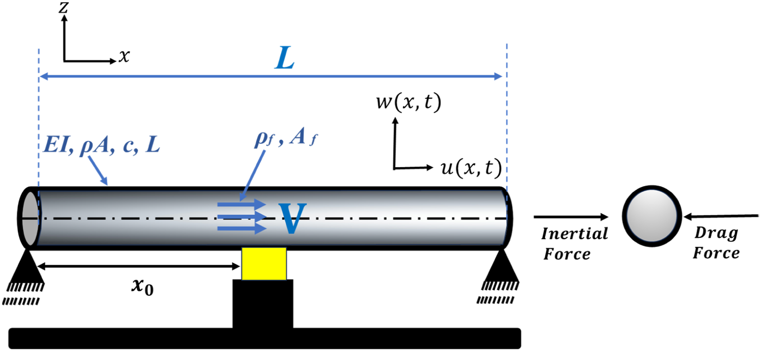
, the simplified physical model of a submarine pipeline conveying fluid on rigid supports and subjected to regular waves and marine currents is shown in Figure 1(a). An equivalent simplified model of the submarine pipeline, considered as a uniform structure conveying fluid with both ends simply supported, is shown in Figure 1(b). The system consists of a pipeline of length Sketch of (a) the submarine pipeline conveying fluid system, and (b) an equivalent simplified model under sea wave excitation, modeled as a Morison force (inertia force and drag force).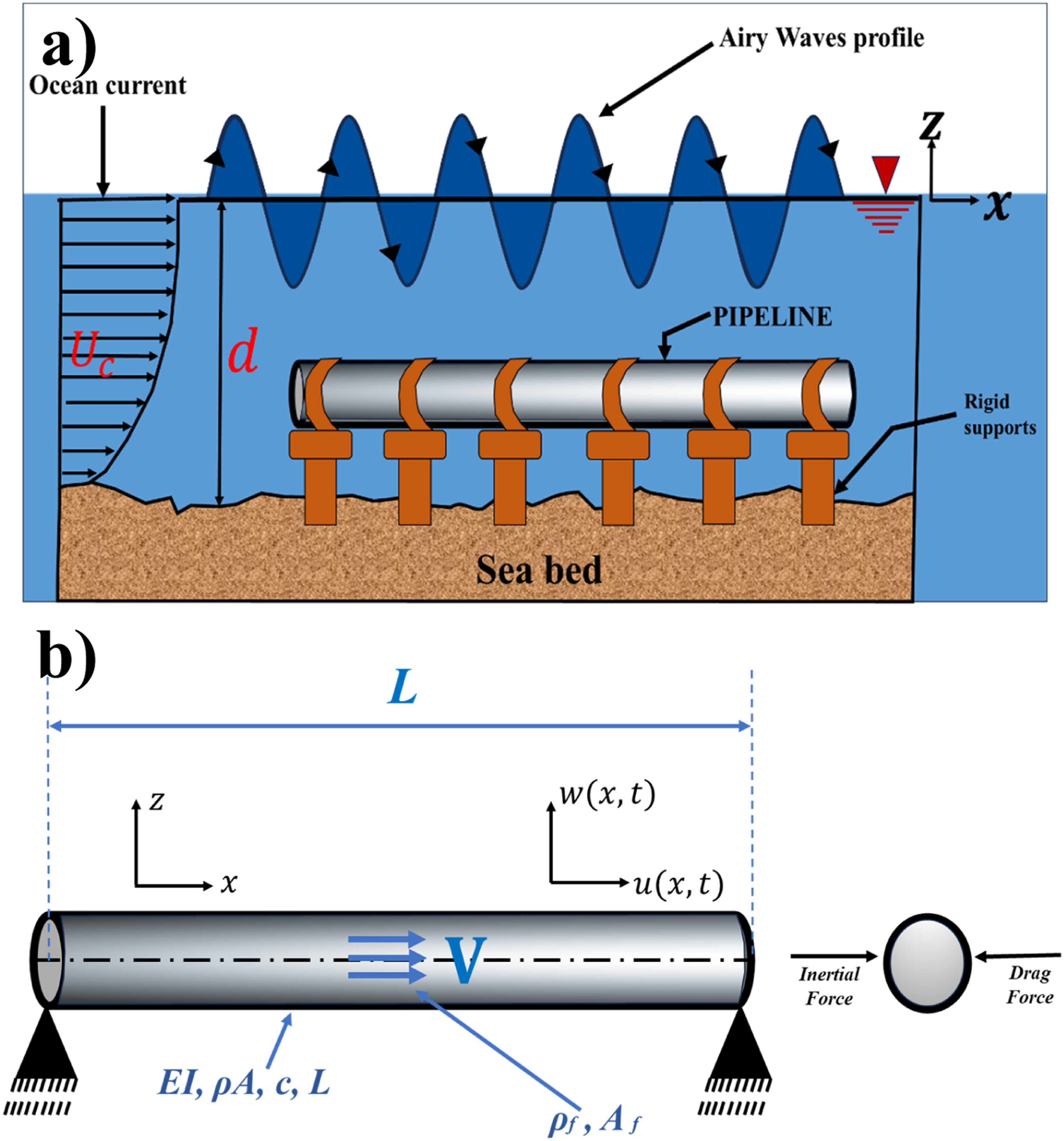
2.1. Mathematical modeling: System without control
The generalized Hamiltonian principle23,24 can be applied to establish the mathematical model of the coupled planar motion of the submarine pipeline in the following form:


According to assumptions (i), (iii), and (v) listed above, the kinetic energies
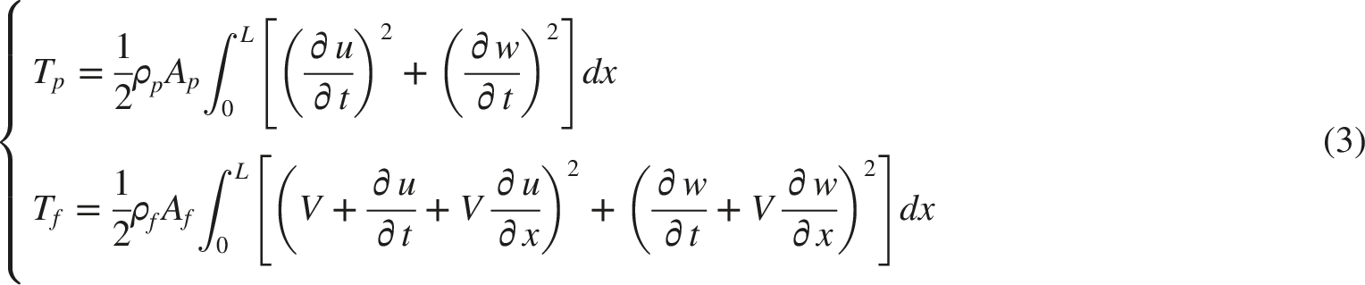
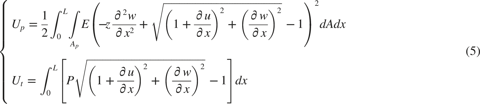
The total potential energy is the sum of the strain energy caused by a variation of the stress with respect to the initial configuration of the pipeline, denoted

According to assumptions (i) and (iv) listed above,

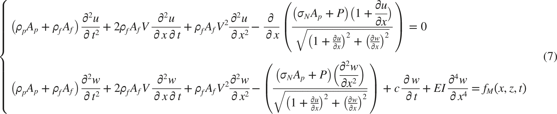

Since the nonlinear vibration involves small but limited stretching, the coupling between longitudinal and transverse motion is neglected, and only the lowest-order nonlinear terms are retained. Moreover, the displacements both transverse and longitudinal are assumed to be much smaller than the pipe length. We assume that


Considering that the initial axial tension


By integrating the equation (11) with respect to x twice, and considering the initial and boundary conditions

Then, by substituting the equation (13) into the governing equation (12), we obtain:

The sea wave excitation is formulated using Morison’s equation and Airy theory26,27 and is given by:


At the bottom of the sea,

Also, based on the work of Michael Isaacson
28
, and other authors29,30, the nonlinear expression of the wave drag force in Morison’s equation is obtained through its Taylor expansion as follows:

Considering the Taylor expansion for

Hence, by substituting the equation (19) into the equation (15), we finally obtain the load expression below:

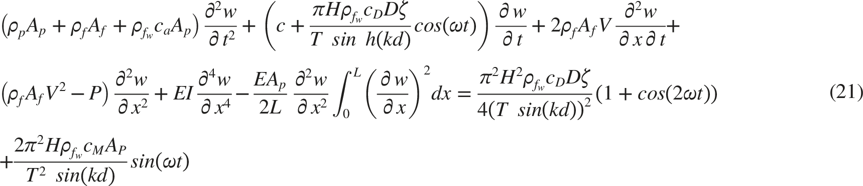
Equation (21) is the mathematical equation governing the transverse displacement response of the submarine pipeline conveying fluid under wave load excitation. Introducing the following dimensionless variables into equation (21):
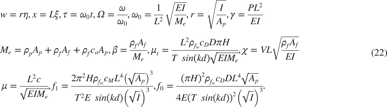
The dimensionless equation is obtained as:

2.2. Modal equation
To perform the analytical analysis, we resort to an assumed mode expansion. Specifically, it is assumed that

Figure 2 presents the amplitude of deformation of the first three mode shapes of the pipeline for a length Mode shapes of the pipeline for 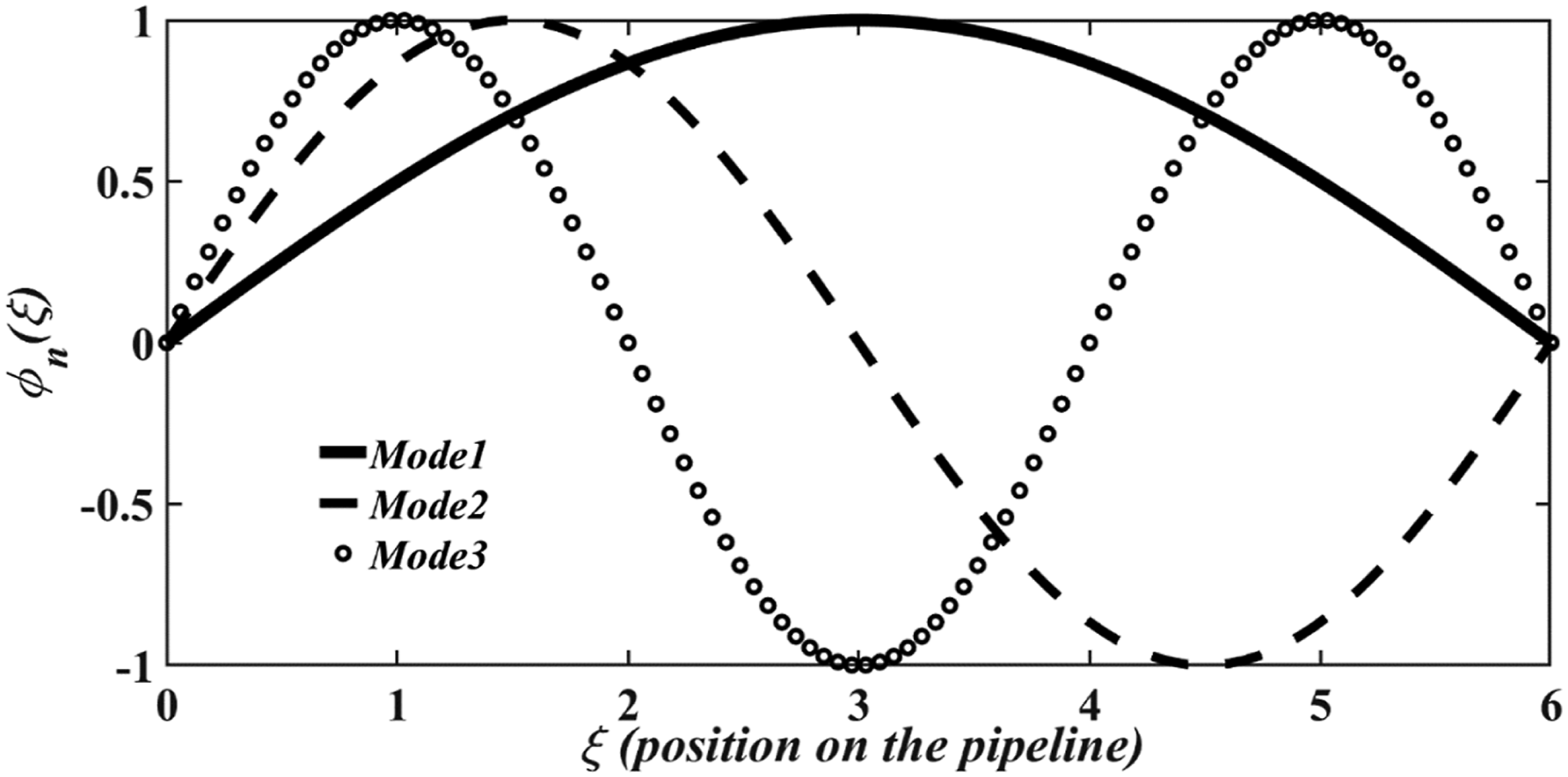

3. Natural frequency of the structure versus critical flow velocity of the internal fluid
In this section, we determine the critical flow velocity as function of the natural frequency. To do so, the dimensionless equation (23) is rewritten in absence of external loads and the nonlinear term (as shown in Refs. 10 and 15):

It is well known that the solution of equation (26) can be taken as

Geometrics parameters of the pipeline.
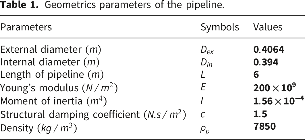
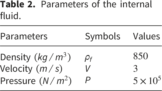
Parameters of the internal fluid.
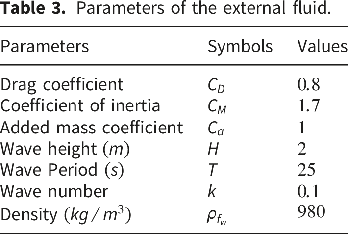
Parameters of the external fluid.
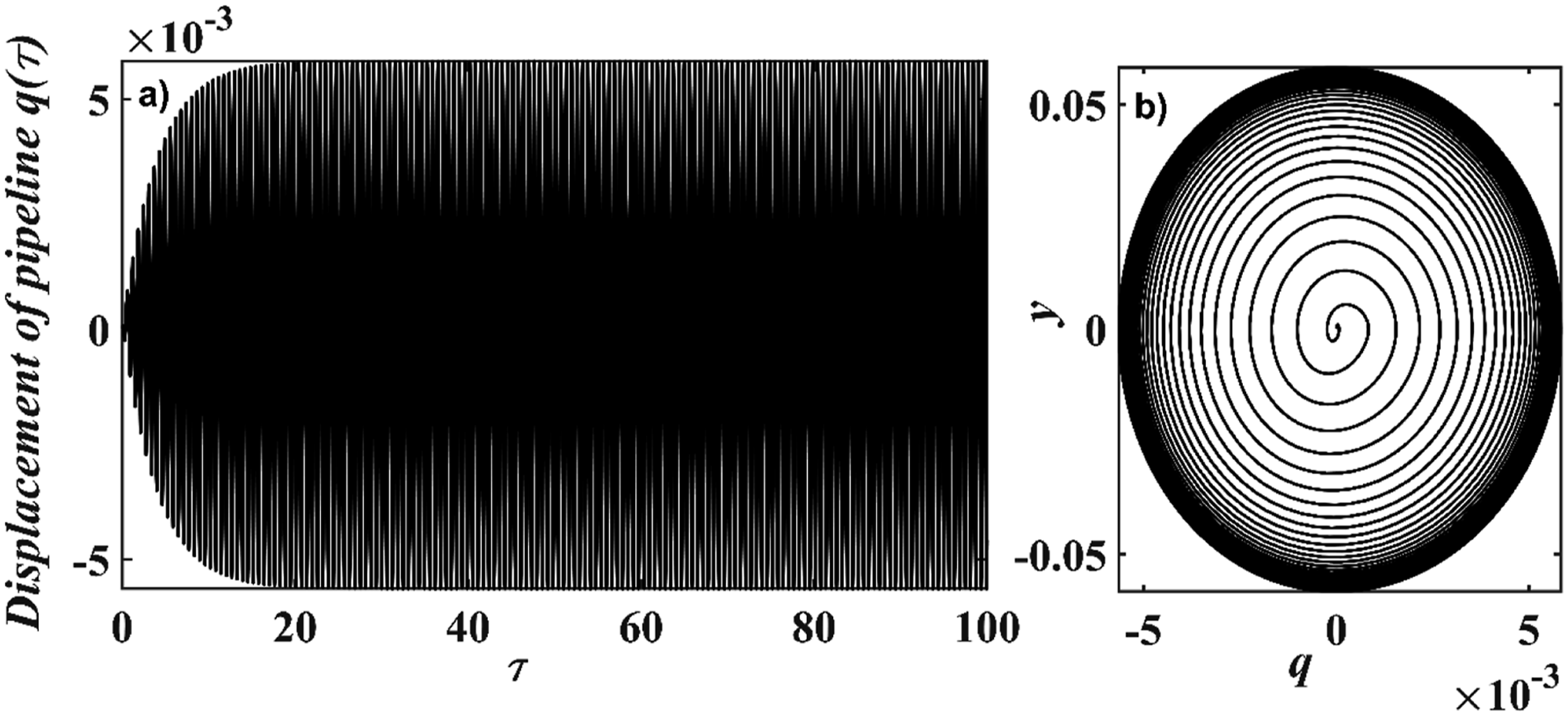
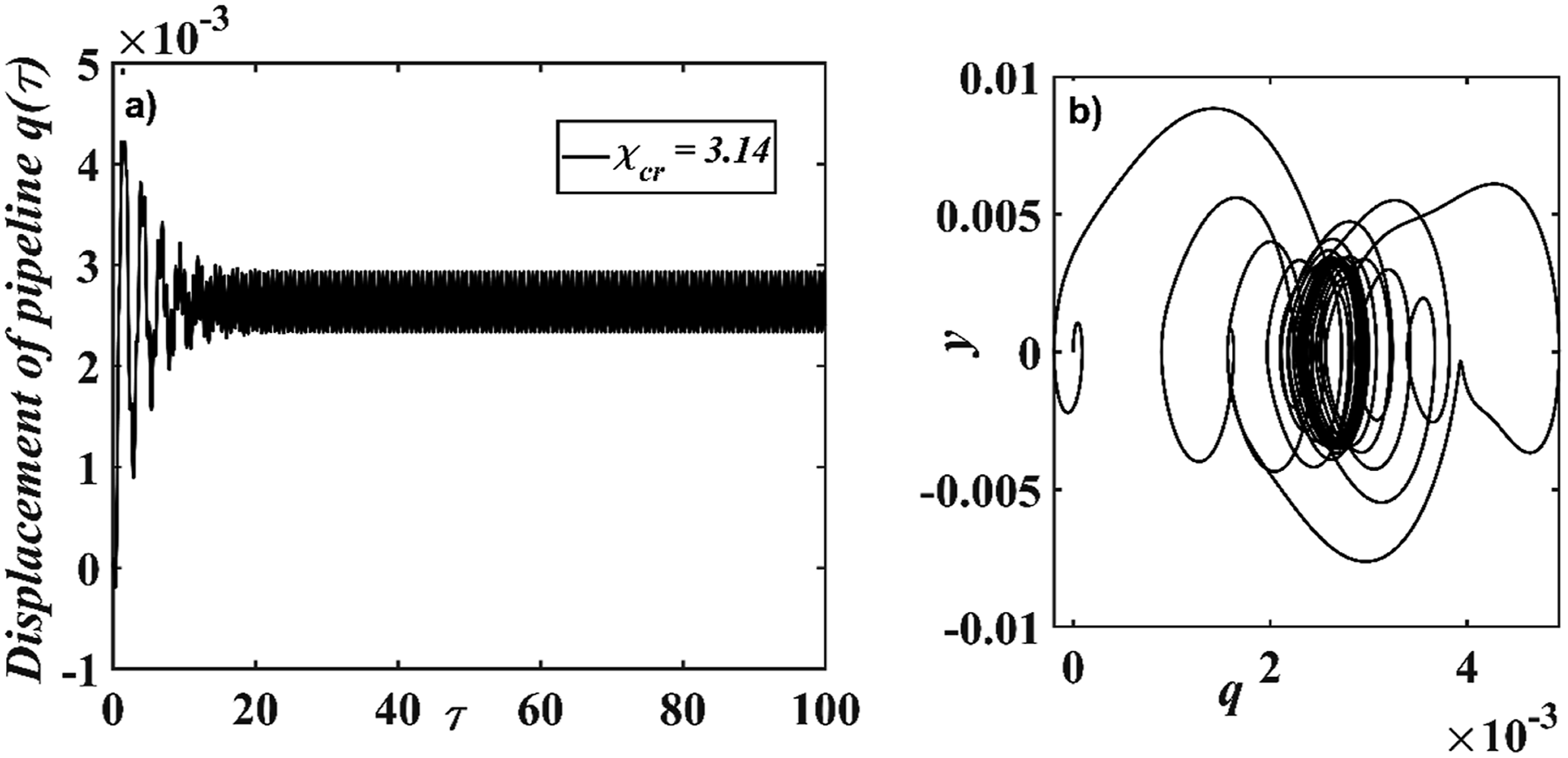
As one can observed in Figure 3, by increasing the dimensionless flow velocity of the fluid, the natural frequency decreases. We obtain two values of the critical velocity: one for the first mode of vibration, denoted Natural frequency of the pipeline versus the flow velocity of the internal fluid for the first and second vibration modes. (a) Time series of the displacement of the pipeline and (b) the phase portrait in plane (q, y) for (a) Time series of the displacement of the pipeline and (b) the phase portrait in plane (q, y) for 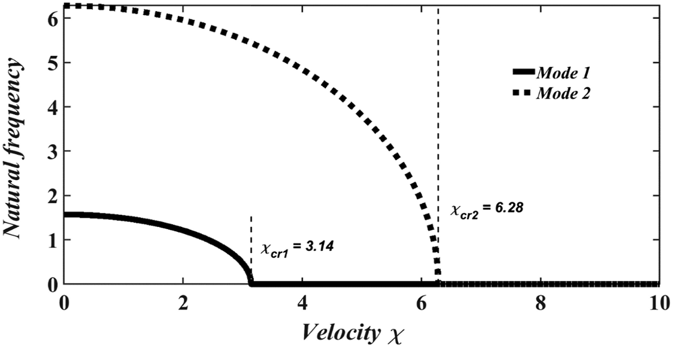
4. Effect of the critical flow velocity of the fluid on the amplitude response of the pipeline
Figure 4 presents the time series of the displacement (Figure 4(a)) and the phase portrait in the plane (q, y) (Figure 4(b)) of the pipeline response for a dimensionless internal fluid flow velocity
5. Effects of the wave frequency and the internal fluid flow velocity on the vibration amplitude of the pipeline
In this section, a multiple time scale method
11
is employed to obtain an analytical approximate solution. Two-time scales are defined: one fast time and one slow time. The time differentiation is expanded as follows:



After this expansion, the different types of resonance of the system are analyzed.
5.1. Harmonic resonance of the sub-marine pipeline conveying fluid
When the wave frequency is equal to the natural frequency or equal to half of the natural frequency of the fluid-conveying pipeline, resonance phenomena generally occur, known as primary and secondary resonances, respectively. We will then examine each of these resonance types case by case. By substituting the equations (28) and (30) into (29) and equating the coefficients of the same powers of 

The solving equation (31) gives a solution in the form;
By substituting equation (33) into equation (32), we obtain:
➢
The deviations of 

By using the polar notation 
For a steady-state response, the solution is given 
➢
The deviations of 
As before, by considering the same hypotheses and the same steady-state response conditions, and after mathematical expansion, we obtain the following amplitude equation for secondary resonance:
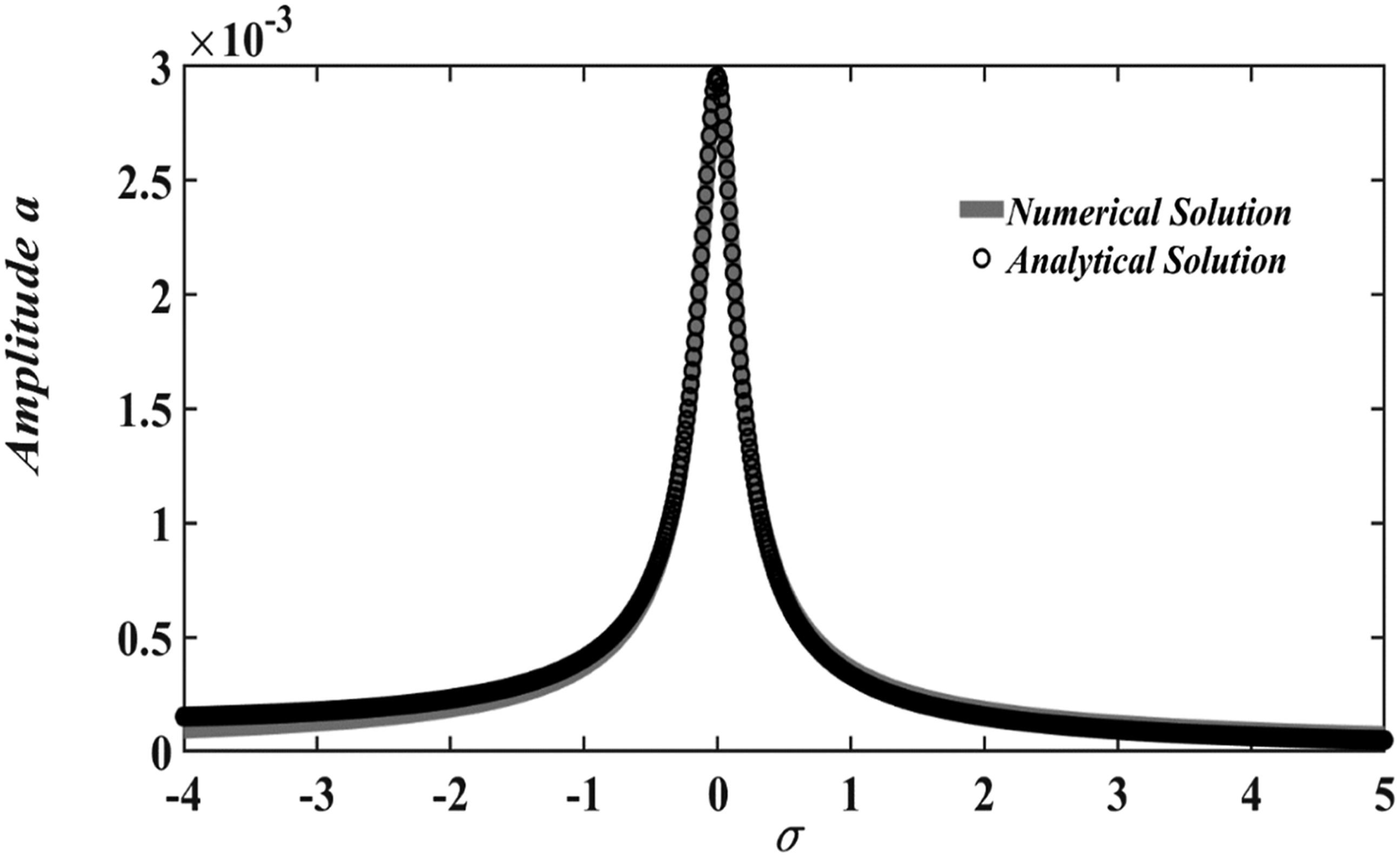
Equations (38) and (40) represent the nonlinear amplitude responses for the primary and secondary resonances of the system. The oscillation amplitudes are evaluated using the dichotomy method
11
, and compared with numerical simulations obtained via the fourth-order Runge–Kutta method11,32, as shown in Figures 6 and 7. For the investigated parameters, the numerical results are found to be in good agreement with the analytical predictions. Both figures show that a resonance peak exists for a specific value of the detuning parameter Steady-state vibration amplitude of the pipeline as a function of the detuning parameter Steady-state vibration amplitude of the pipeline as a function of the detuning parameter 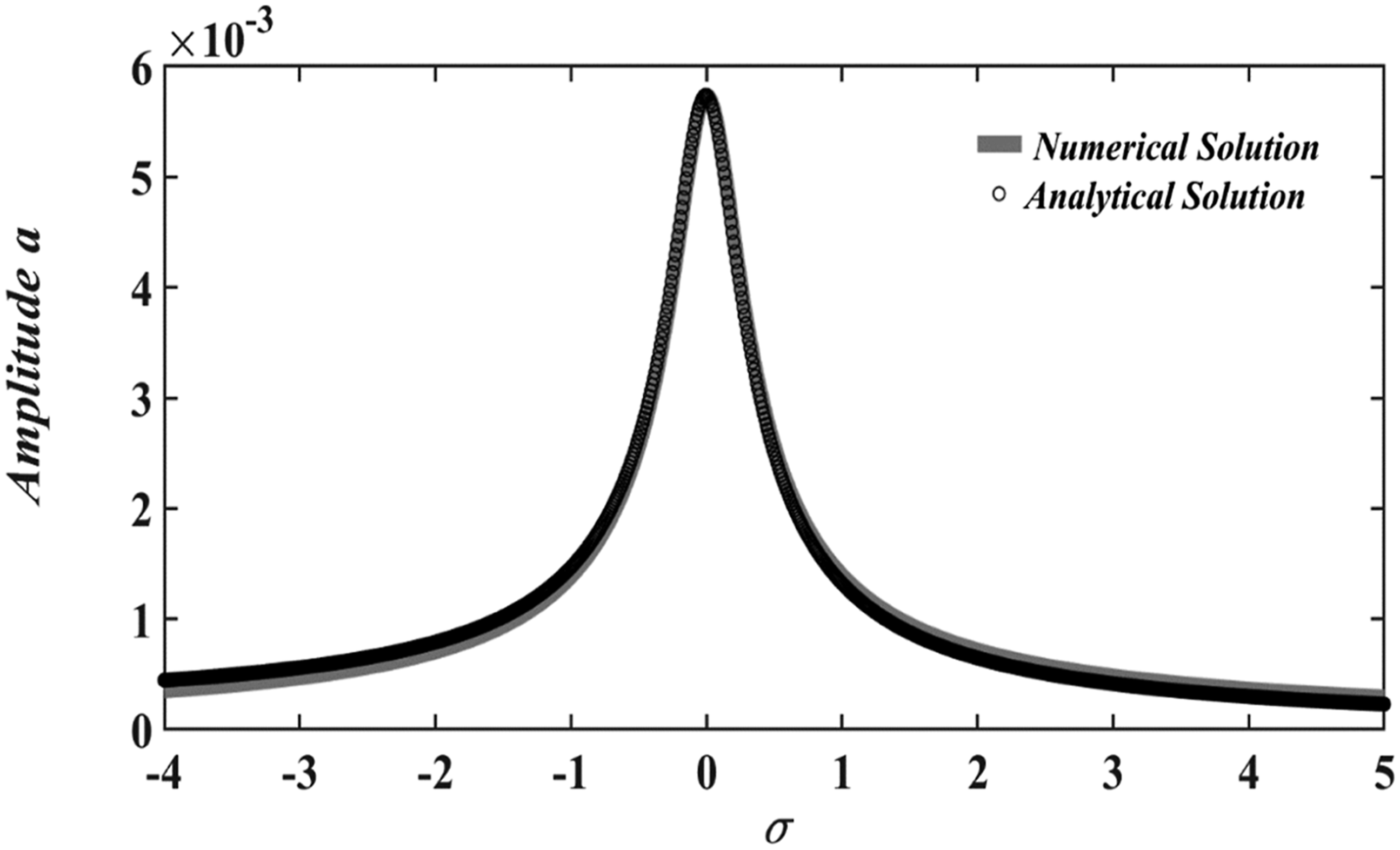
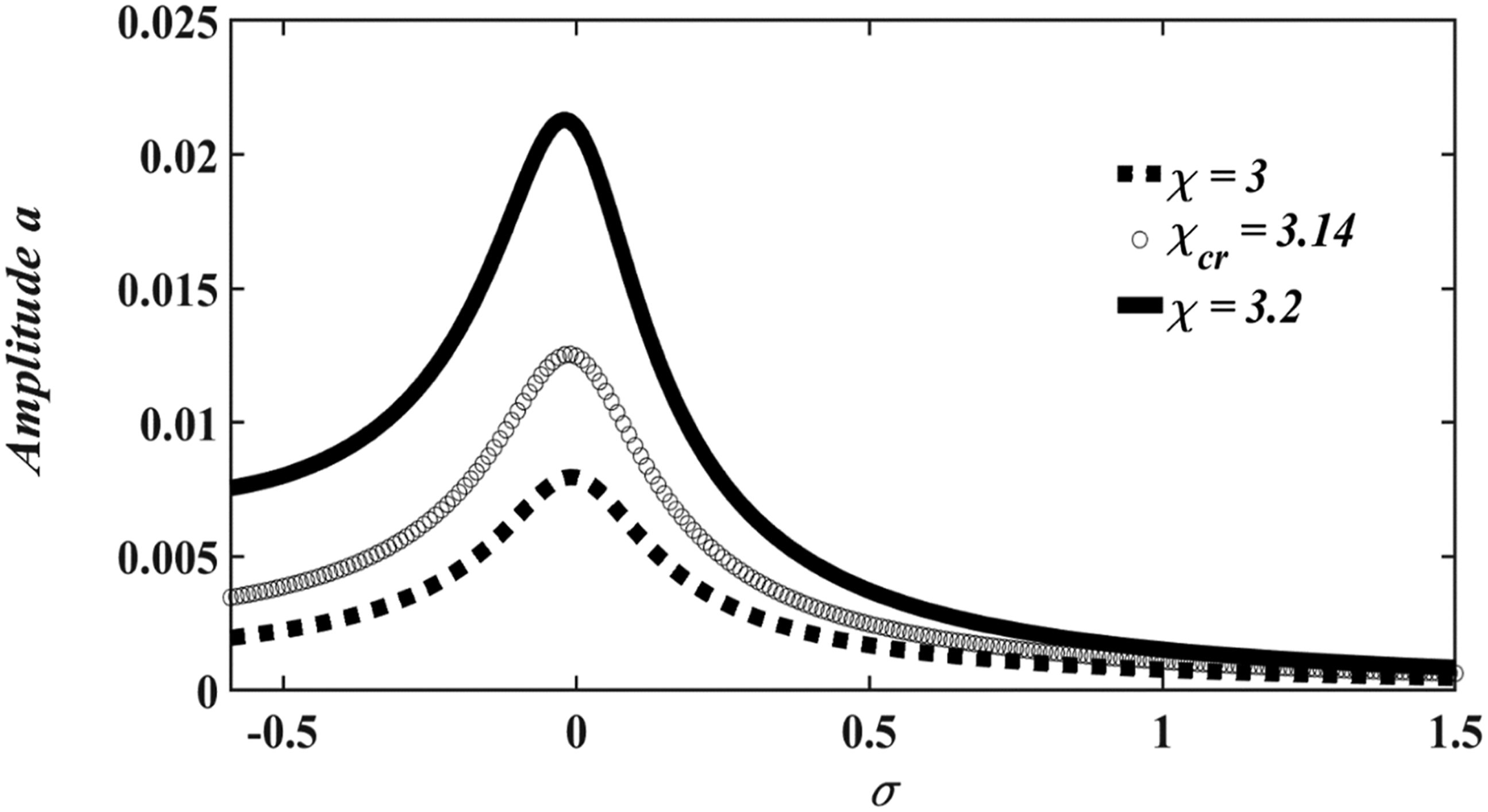
Figures 8 and 9 show the effect of the internal fluid flow velocity (subcritical, critical, and supercritical) on the steady-state amplitude a and the detuning parameter 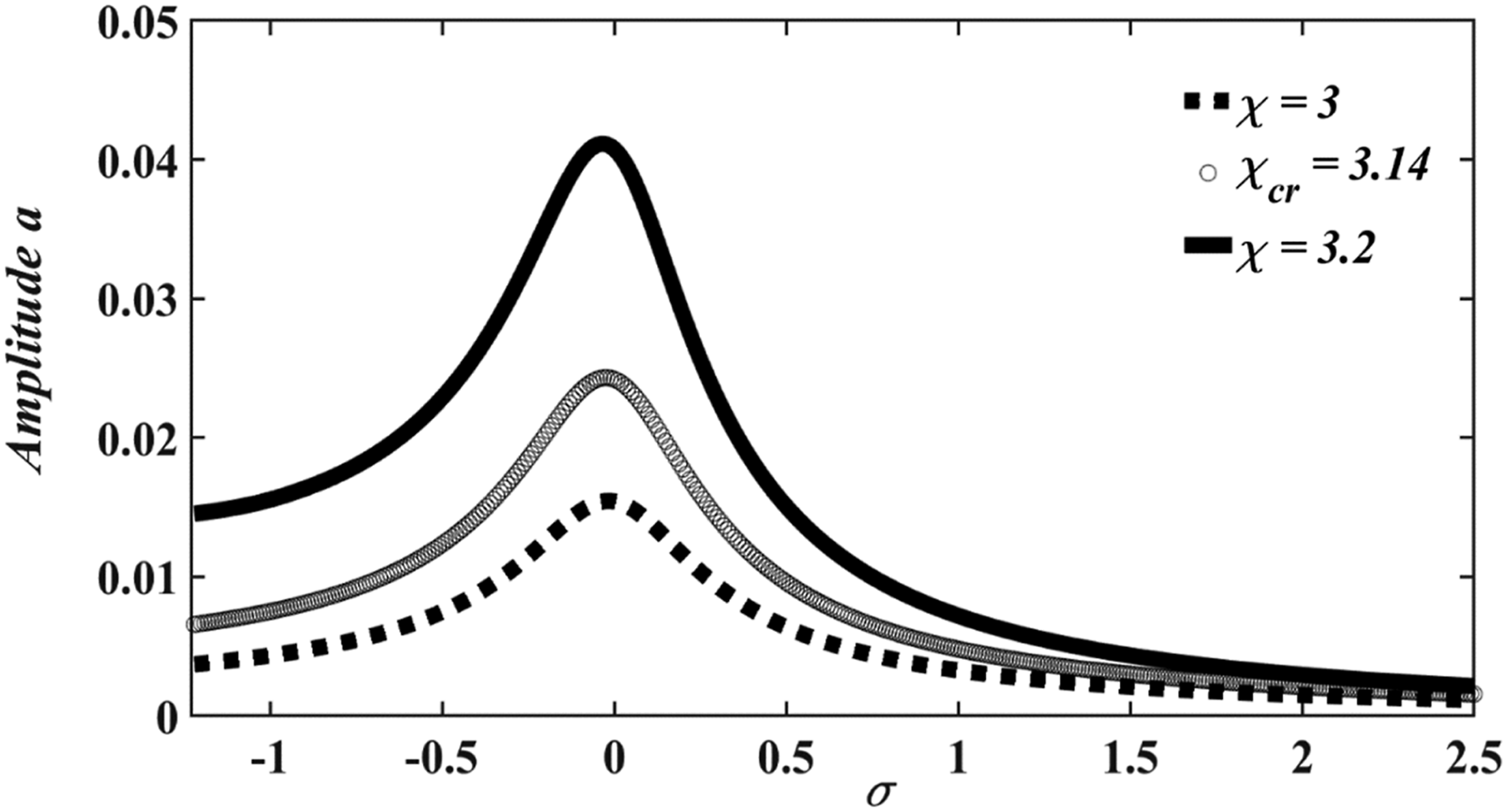
5.2. Superharmonic, subharmonic, and combined harmonic resonance of the submarine pipeline
When the wave amplitudes become very large, the behavior of the system shifts to other types of vibrational resonance, namely superharmonic, subharmonic, and combined harmonic resonance. By applying the same method and development as previously described, we obtain the following amplitude equations:

Hence, a solution to (41) is in the form:

Substituting equation (43) into equation (42), and after mathematical expansion and simplification, the following expression is obtained: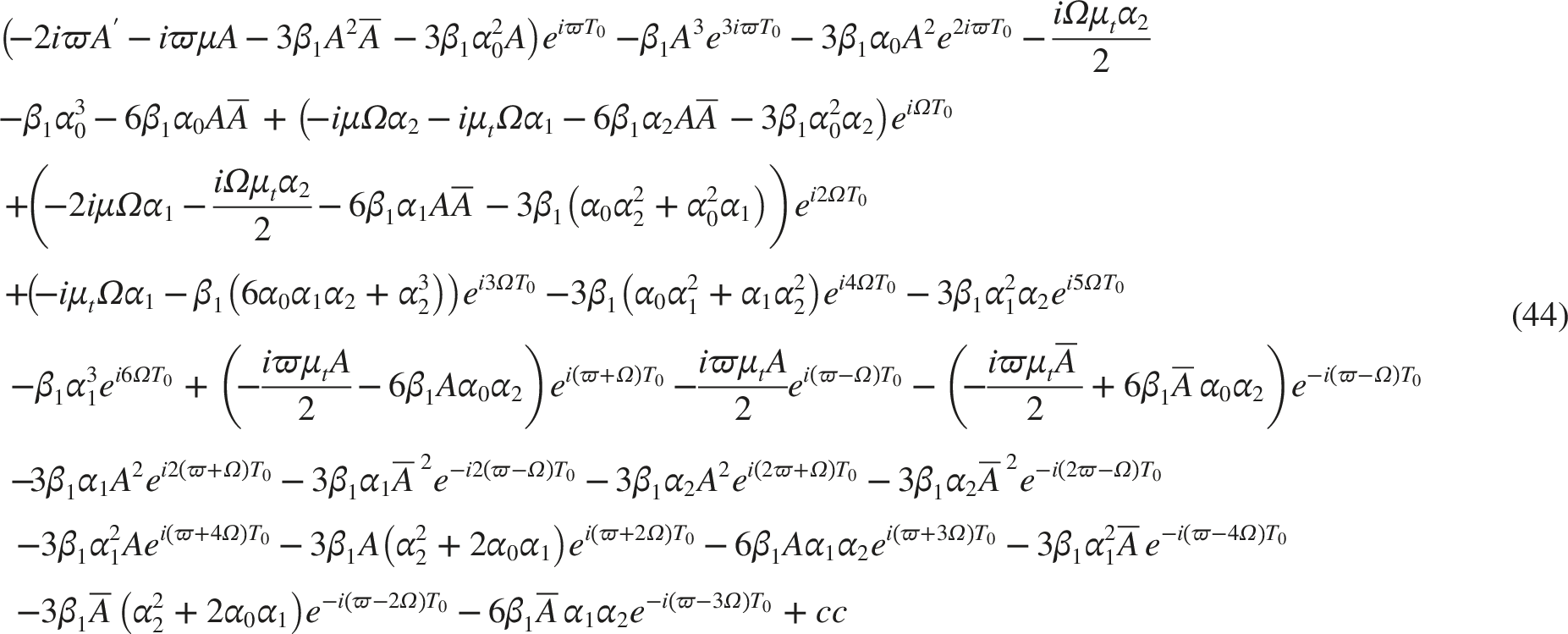
a. Investigation on super-harmonic resonance of the system response.
By considering 
Using the polar notation 
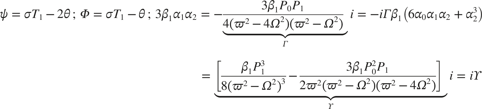
As before, considering the same steady-state response conditions, and after mathematical expansion, we obtain the following amplitude equation:
Now, by considering 

with
By considering the same conditions for steady state response, and after mathematical expansion, we obtain the following amplitude equation:
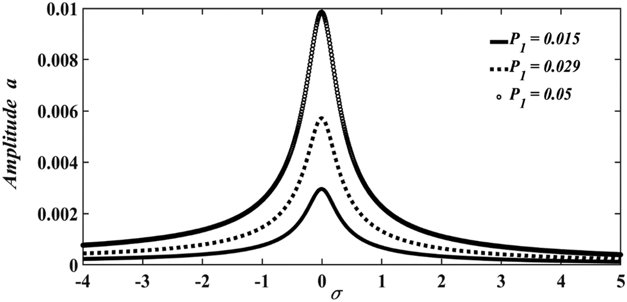
The effect of the internal fluid flow velocity is observed by representing the steady-state amplitude of the pipeline as a function of the detuning parameter in Figure 11 for (a) 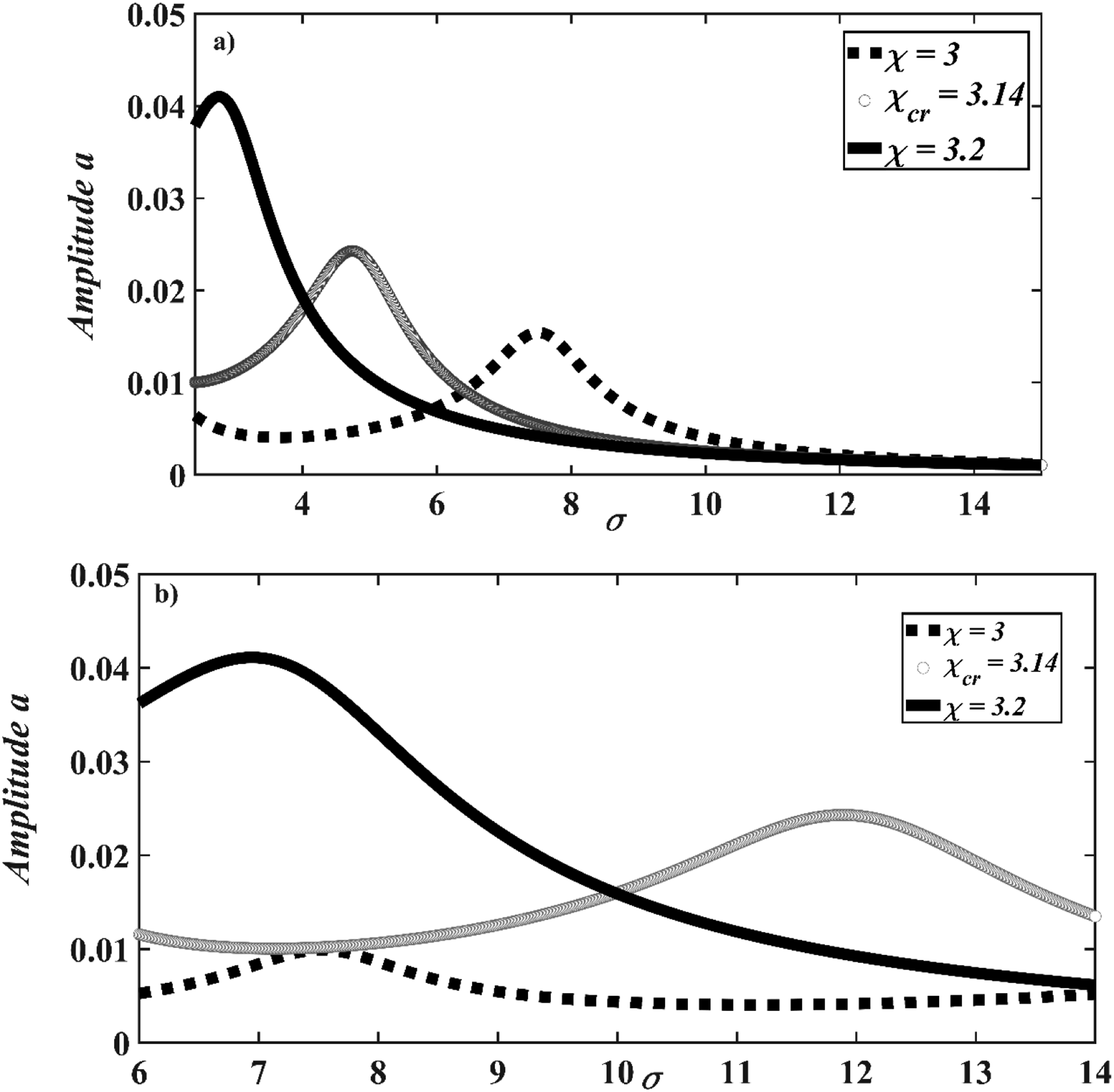
To highlight what we consider an original contribution, the fluctuations generated by the approximation of the drag force which, after approximation, presented a notable increase in the peak resonance amplitude of the structure are investigated. The data reported in Figure 12 show how an increase in this load parameter 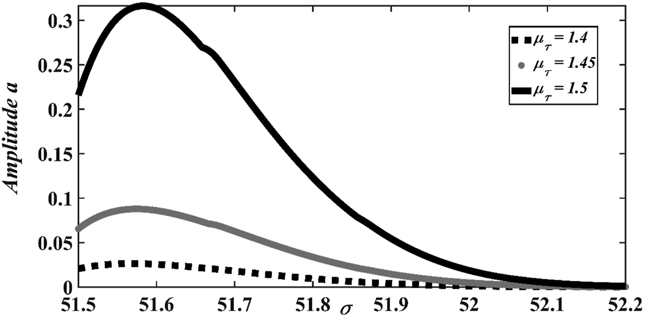
b. Investigation on Subharmonic resonance of the system response.
In this part, two cases are treated:
First case ( 

with
Given that the steady-state response conditions are satisfied 

The data reported in Figure 13 show the effect of the internal fluid flow velocity on the steady-state vibration amplitude of the pipeline versus the detuning parameter 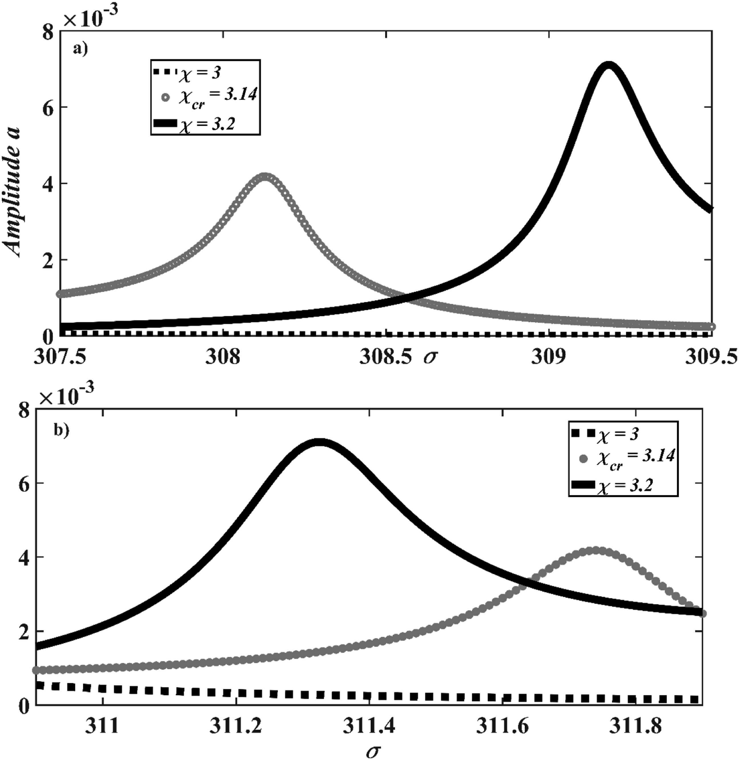
c. Investigation on combined harmonic resonance of the system response.
In this part, the following situation is considered:

By inserting the polar form 
with
Given that the steady-state response conditions are satisfied 

For the combined harmonic resonance of the system illustrated in Figure 14, a notable and progressive increase in the peak resonance amplitudes of the structure is observed with respect to the different flow velocities of the internal fluid considered. Furthermore, for the same flow velocity conditions, the peak resonance amplitudes in the case of combined resonances are larger than those in the case of subharmonic resonances. This indicates that the flow velocity has a more considerable influence when the wave frequency is close to the combined resonance frequency than to subharmonic resonance. A control technique will be used to reduce this vibration amplitude.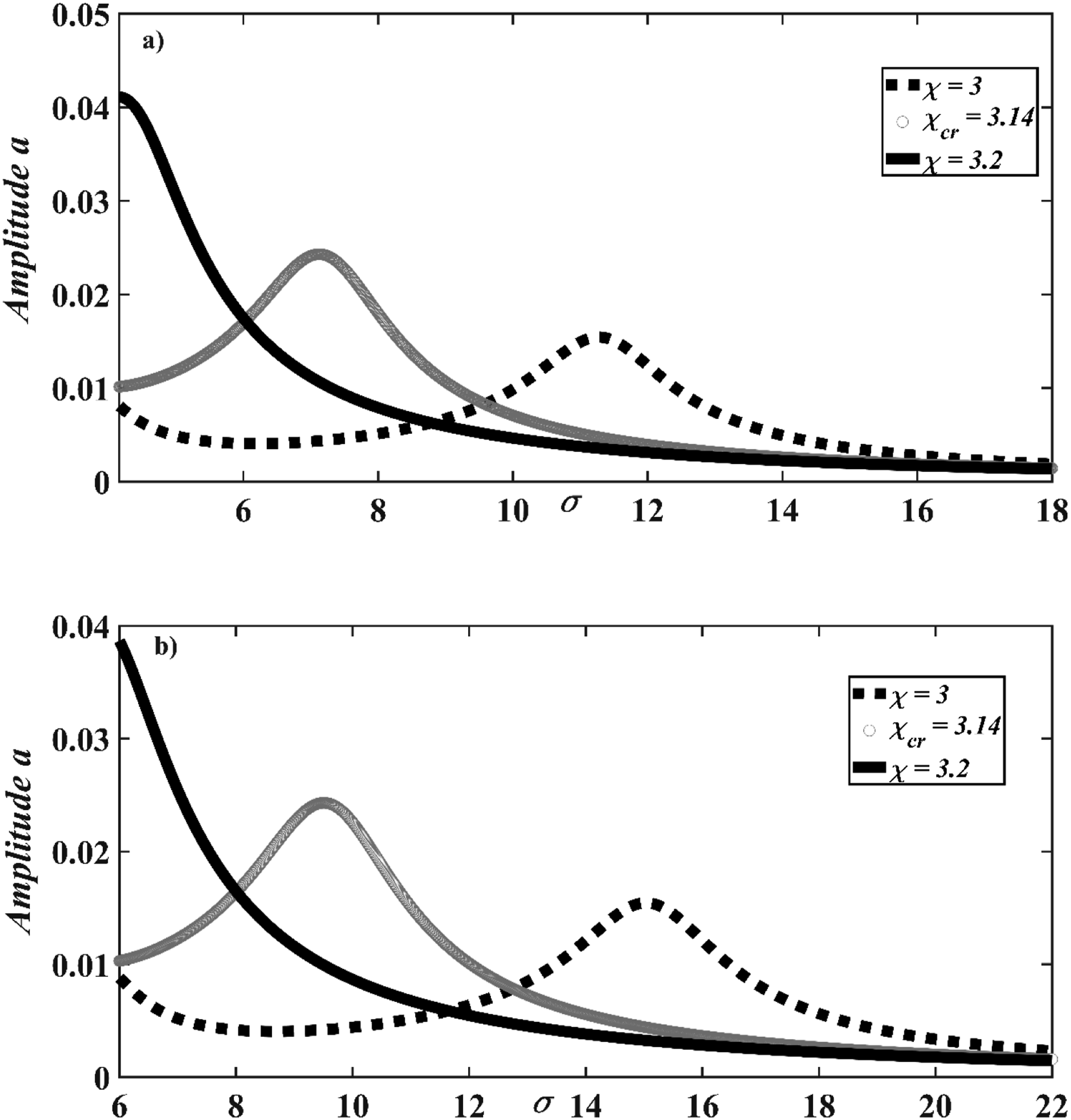
6. Effect of the NES controller on the vibration amplitude of the submarine pipeline conveying fluid
6.1. Description of the control model
Since the vibration of the pipeline has been fully characterized as shown in Part 2 of this work, the next step is to minimize the dynamic deflection of the structure. To this end, an essentially nonlinear damped attachment is expected to irreversibly absorb the vibrational energy of the structure. A suitable way to reduce vibration in mechanical structures conveying fluid and subjected to regular wave excitation is to use a Nonlinear Energy Sink (NES) controller. The NES functions as an effective vibration absorber for nonlinear systems and has recently been reported to engage in resonance over a very broad frequency range
33
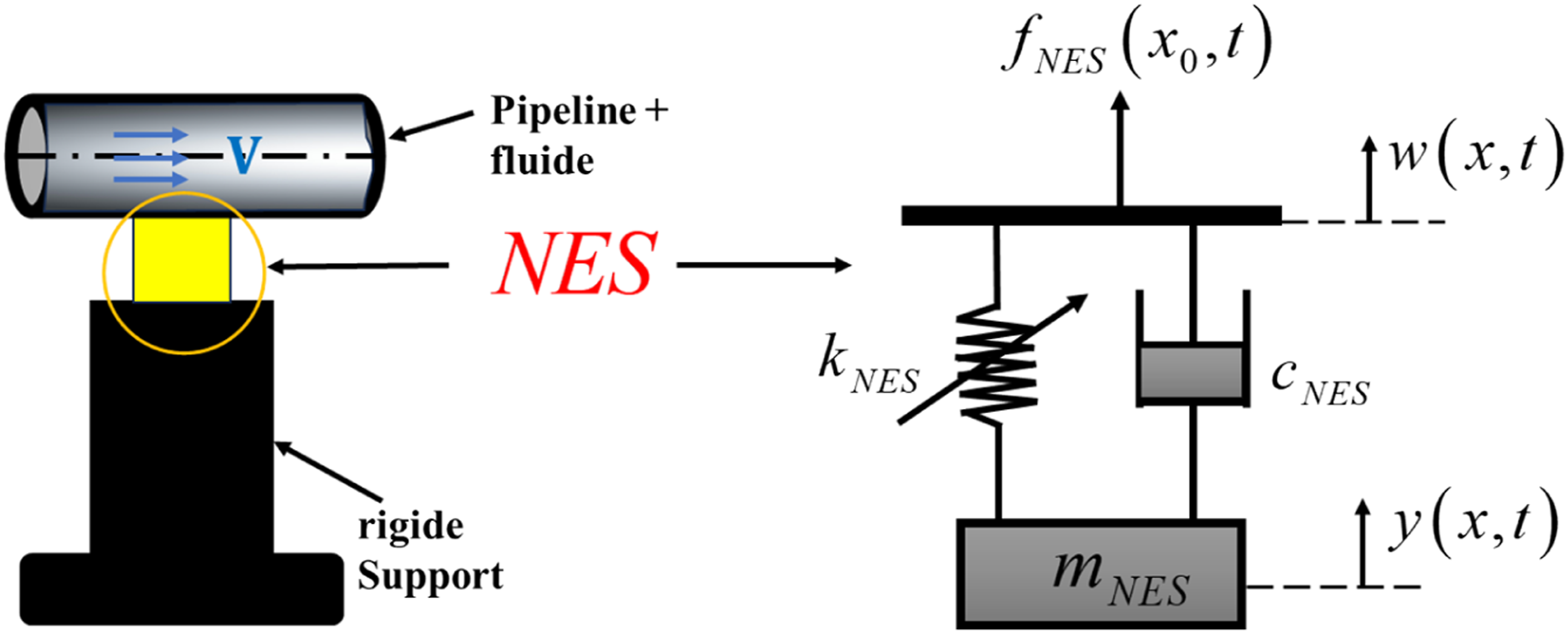
. Figures 15–17 clearly illustrate the pipeline with the controller on the sea floor, followed by a mechanical model of the controller and finally a simplified model of the system. Schematic diagram of a sub-marine pipeline on the sea floor with integrated vibration control mechanism. Simplified model of the NES controller. Simplified model of the submarine pipeline with NES controller.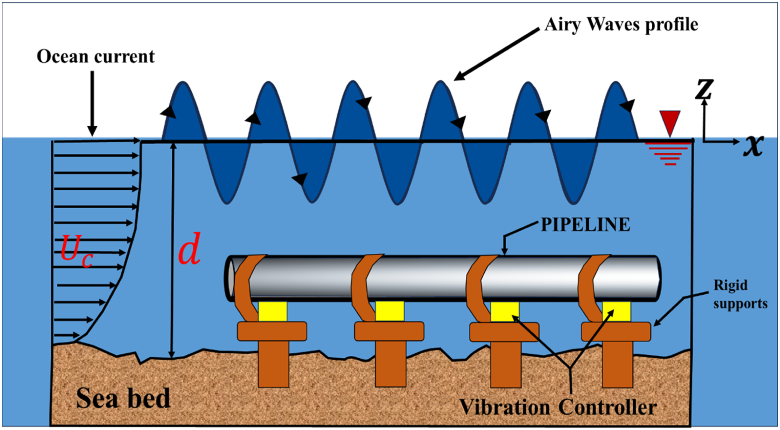
By taking into account the same considerations and hypotheses as before, the mathematical model describing the behavior of the submarine pipeline conveying fluid with an integrated vibration controller can be expressed as follows:

By substituting Eqs.(20) and (60) into (59), we obtain the following equation:

By applying the Lagrangian method
34
on the discrete system of the controller (Figure 16), the equation of motion of the controller is expressed as:
Hence the governing equation of the pipeline conveying fluid under the action of wave loads with integrated vibration controller is given by: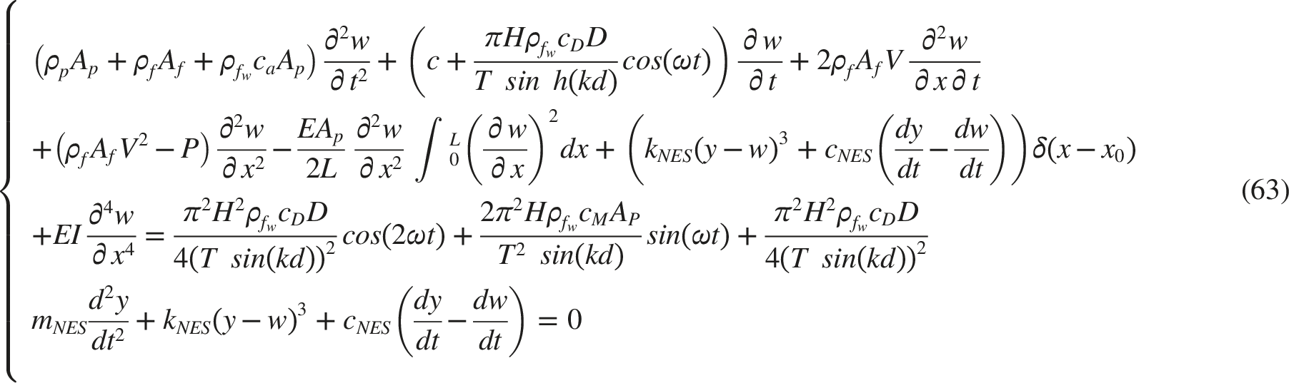
Consider the following dimensionless variables:



By substituting (64) in (63) and after some mathematical expansion and reduction, we obtain the following dimensionless equations:

6 2. Modal equation and effectiveness of the controller
To obtain the modal equation, we apply Galerkin’s method as done in the first part of this work. Thus, using equation (24) and after some manipulations, the modal equation of motion for the fundamental vibration mode (n=1) is given by:

The effectiveness of the NES coupled to the transverse vibration of the fluid-conveying pipeline is demonstrated. The numerical method based on the fourth-order Runge–Kutta algorithm is used to solve the coupled equations 66a and 66b in order to obtain the displacement amplitude of the pipeline with and without the NES controller.
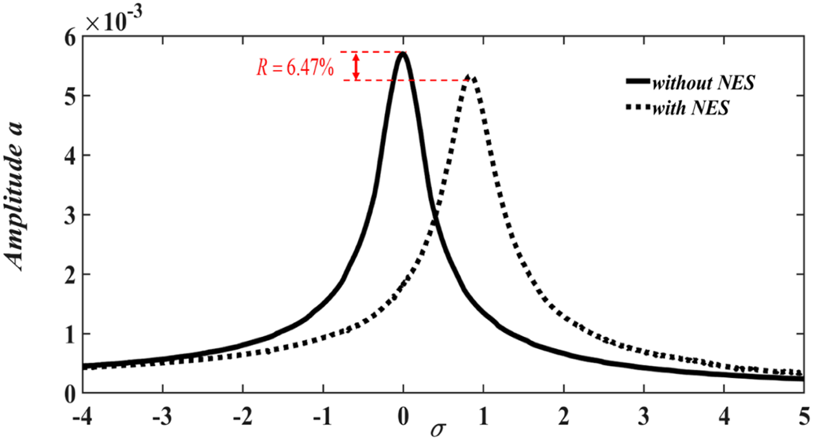
Figure 18 illustrates the time displacement responses of the structure with and without the NES controller. It is observed that the viscoelastic effects and the mass of the controller are more pronounced, and the vibration of the system with the NES controller is drastically reduced compared to the system without the controller. This indicates that the NES controller is effective and ensures the safety of the structure. A reduction percentage of R=58% is observed for values of Comparison of the pipeline response with and without NES (gray: pipeline coupled with NES; black: pipeline without NES) for Effectiveness of the controller on the steady-state vibration amplitude of the pipeline as a function of the detuning parameter 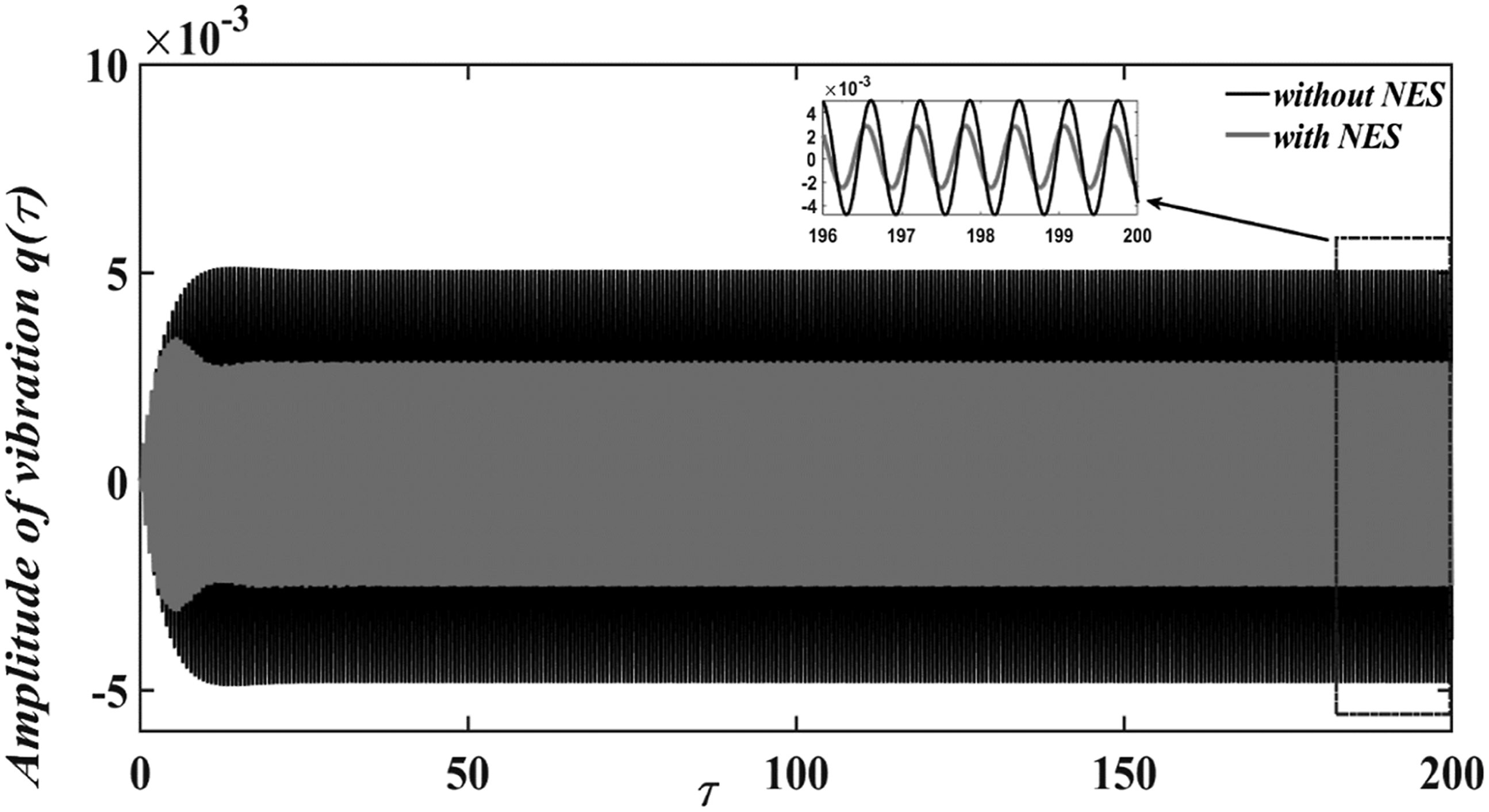
7. Conclusion
Summing up, we have investigated the dynamic behavior of a submarine pipeline conveying fluid, with and without a vibration controller, under wave excitation. The Euler–Bernoulli beam theory was used to model the dynamic behavior of the pipeline. Wave excitation was modeled as a hydrodynamic force consisting of inertial and Morison-type drag components. After a brief description of the physical model, the governing equations of the system, with and without control, were established using the generalized Hamiltonian variational principle. A nonlinear energy sink (NES)-type controller was employed to reduce the vibrations of the pipeline model. An analytical technique based on the multiple time scale method was applied to the linearized system to illustrate how the internal fluid flow velocity, controller parameters, wave amplitude, and fluctuation parameter of the drag force affect the system’s response. The results were compared with numerical solutions of the modal equation, showing good agreement. The effect of the internal fluid flow velocity on primary, secondary, superharmonic, subharmonic, and combined resonance states has been investigated. The analysis leads us to the conclusion that increasing the internal fluid flow velocity increases the peak amplitude response of the pipeline. This means that a high value of this velocity can contribute to destabilizing the system. Another interesting finding is that increasing the wave excitation intensity also increases the resonance (peak amplitude) of the pipeline. This important result demonstrates that the highest wave excitation intensity can cause large displacements and contribute to destabilizing the structure. Furthermore, the resonance phenomenon appears as the wave frequency increases, for all types of resonant states. To highlight what we consider as new, the fluctuations generated by the approximation of the drag force which, after approximation, presented a notable increase in the peak resonance amplitude have been investigated. This load parameter can cause large displacements of the pipeline and thus lead to significant consequences for the structure. Finally, a NES controller has been used to mitigate the vibrations of the pipeline. The results show an effective vibration reduction of 58%.
This exploratory analysis has, of course, its limitations. Most importantly, for more realistic simulations, one might consider different values for the pipeline parameters, chosen with greater realism rather than, as in the present work, to accelerate simulations and highlight qualitative results. For example, only the first mode was used in Galerkin’s method, and higher coupled modes were not included. It would be interesting to extend this work to incorporate these two main ideas. Nevertheless, we hope that the qualitative conclusions obtained in this study can provide reference values for such developments.
Footnotes

Funding
The authors received no financial support for the research, authorship, and/or publication of this article.
Declaration of conflicting interests
The authors declared no potential conflicts of interest with respect to the research, authorship, and/or publication of this article.