






Abstract
The interlaminar cracks in carbon fibre composites formed by laser in-situ forming are prone to development and expansion in the interlayer of the resin zone when subjected to shear forces, and lead to delamination failure ultimately. To enhance the mechanical properties of CF/PEEK composite components, a 1064 nm pulsed laser scanning method was employed to construct laser-induced graphene (LIG) on the surface of CF/PEEK prepreg in this paper. The CF/PEEK prepreg with LIG constructed on its surface was then formed and prepared into CF/PEEK composite laminates through continuous laser-assisted heating. The effects of typical process parameters, including scanning spot spacing, heating temperature and placement pressure, on the interlaminar shear strength (ILSS) and porosity of CF/PEEK composite laminates were investigated. The research results indicate that, compared to the laser in-situ formed CF/PEEK laminates without LIG interlayer reinforcement, the porosity of the laser in-situ formed CF/PEEK laminates with LIG interlayer reinforcement increased from 2.81% to 3.03%. However, the ILSS of the laminates increased from 54.4 to 62.7 MPa, representing a maximum improvement of 15%. By constructing LIG on the surface of CF/PEEK prepreg, the ILSS of CF/PEEK composite components was significantly improved. The research results lay a technological foundation for the preparation of CF/PEEK composite components with high mechanical properties.
Keywords
Introduction
Laser in-situ forming has many advantages such as high efficiency, low cost, precise and controllable heating temperature and good forming quality. It is one of the most promising methods in the additive manufacturing process of thermoplastic carbon fibre composites.1,2 Laser in-situ forming technology stacks the prepreg tape layer by layer through laser heating and roller compaction to form laminated plate components. Interlaminar properties are critical to the structural reliability and service life of composite laminates, interlaminar shear strength (ILSS) directly dominates the bearing capacity and failure mechanism of components under shear, bending and impact loads. Insufficient ILSS tends to induce interlaminar cracking, delamination propagation and even catastrophic structural failure. Therefore, improving ILSS is of great engineering significance for expanding the application of carbon fibre composites in high-performance load-bearing structures. However, when the laminate is subjected to shear force, the cracks are easy to develop and expand in the interlayer resin zone, which eventually leads to the delamination failure of the component.3,4 This limits the practical application of laser in-situ forming components. To address the weak interlaminar performance, researchers have developed various strategies including matrix toughening, fibre surface modification, interlayer toughening layers and nanofiller incorporation.5,6 Although these methods improve interlaminar toughness and shear resistance to a certain extent, most suffer from complex procedures, poor compatibility with in-situ manufacturing, uneven dispersion of toughening phases or high cost, making them difficult to integrate into efficient and automated manufacturing routes. To improve the interlayer performance of composite components, the rapid development of nanomaterial filling technology has been a viable approach in recent years.7–9
Compared with thermoplastic carbon fibre composites, the research on filling and reinforcing modification of thermosetting carbon fibre composite resin matrix is more mature. Among the relevant reports, epoxy resin-based carbon fibre composites are the most common. The application of nanomaterials filled10–12 in the interlaminar toughening of thermosetting carbon fibre composites is very successful, and the interlaminar fracture toughness can often be enhanced by more than 100%. Furthermore, the ILSS, flexural strength and tensile strength of the material can also be improved accordingly.13,14 However, the high viscosity and high melting temperature of thermoplastic resin bring challenges to the matrix filling modification of carbon fibre reinforced thermoplastic composites. Su et al. 15 fabricated carbon nanotubes/polyethyleneimine (CNTs/PEI) interlaced layers by solvent casting method, and then inserted the interlaced layers into CF/PEEK prepreg to prepare laminates. It was found that the ILSS and flexural strength of CF/PEEK laminates were increased by 42.9% and 24.7%, respectively. Araceli et al. 16 prepared polymer-modified graphene filler by dispersing graphene into resin solvent and studied the reinforcement effect of graphene in CF/PEEK laminates. It was found that for 5 wt% graphene, the PEEK layer showed a significant increase in modulus (approximately 30%). Sun et al. 17 used AFP (Automated Fibre Placement) technology to prepare CF/PEEK laminates doped with carbon nano paper (BP) between layers, which increased ILSS by 22.7%. Zhang et al. 18 dispersed the treated multi-walled carbon nanotubes (MWCNT) onto the surface of the prepreg by spraying method, and prepared MWCNTs/CF/PEEK multi-scale composites by AFP technology. To improve the bonding strength between MWCNTs and the PEEK substrate, the in-situ consolidated samples were tempered by out-of-autoclave technology, and the ILSS of the samples reached 91.49 MPa, which was 25.21% higher than the CF/PEEK samples. In summary, the combination of nanomaterial filling modification technology and automatic placement in-situ forming technology can effectively improve the mechanical strength of CFRTP in-situ forming components by improving the interlayer performance through the filling of nanophase in the matrix.19,20
Despite the remarkable toughening effect of nanofillers, conventional doping methods usually require additional dispersion, coating or compounding processes, which are inconsistent with the integrated and high-efficiency nature of laser in-situ forming. In recent years, laser-induced graphene (LIG) has emerged as a versatile nanomaterial for interface engineering of thermoplastic composites owing to its in-situ preparability, strong matrix adhesion and excellent mechanical reinforcement effect.21,22 Several pioneering studies have verified that LIG can be synthesised on polymer surfaces and used to tailor the interlaminar properties of fibre-reinforced composites.23–25 For high-performance CF/PEEK composites, LIG has shown unique potential in interlayer toughening without damaging fibre or resin integrity.26,27 However, most existing LIG modification strategies are designed for batch processing or thermoset systems, and few studies have realised in-situ LIG construction and synchronous interlayer reinforcement during laser-assisted automated in-situ forming of CF/PEEK laminates. Existing nanofiller methods require solvent/spray processes incompatible with laser in-situ forming. LIG enables one-step in-situ modification without extra equipment, which fills this gap.
This paper proposes the utilisation of LIG for interlayer reinforcement of CF/PEEK composites during the laser in-situ forming process. Pulsed laser is used to induce LIG formation on the surface of PEEK in the prepreg tapes, and a continuous laser is then used for in-situ forming of the LIG-modified CF/PEEK prepreg tapes, thereby achieving interlayer reinforcement of the layered components. This work provides a new approach for enhancing the mechanical properties of carbon fibre composite components.
Sample preparation and performance characterisation
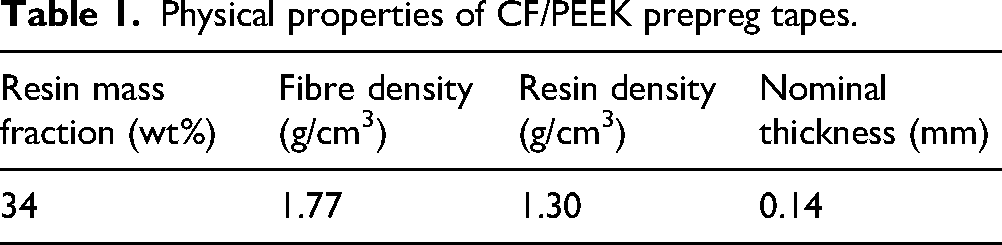
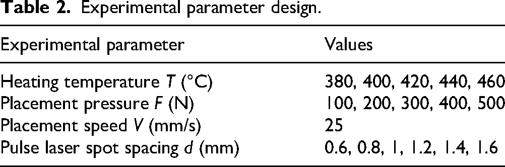
The physical parameters of the CF/PEEK prepreg tape are shown in Table 1. The prepreg tape was scanned by a 1064 nm pulsed laser, and the surface distribution density of LIG generated on the prepreg tape was controlled by changing the spacing of the scanning focus spots. The LIG generated on the surface of the prepreg tape was characterised by Raman spectroscopy. The carbon fibre composite laminates are laid and formed by the laser in-situ forming equipment independently developed by our laboratory. The continuous laser wavelength is 976 nm, and the laser power, placement speed and placement pressure can be varied. Lay the laminate on the flat steel mould in 17 layers, ensuring the laminate thickness exceeds 2 mm, with all layers oriented at 0 degrees. To ensure simplicity and clarity in sample naming, the original CF/PEEK composite laser in-situ forming sample group was named the OC (original composite) group, and the sample group reinforced by LIG interlayer was named the MC (modified composite) group. The designed experimental parameters, obtained by varying the pulsed laser spot spacing, placement pressure and placement temperature, are listed in Table 2. All mechanical and porosity tests were carried out at a test temperature of 20 °C and a relative humidity of 50% RH.
Physical properties of CF/PEEK prepreg tapes.
Experimental parameter design.
The ILSS test sample of the laminated plate is shown in Figure 1, and the size is 12 × 4 × 2 mm. According to the ASTM D2344 standard test method for short beam shear strength of polymer matrix composites and their laminates, the ILSS test was carried out with the universal testing machine of Dongguan Lixian Technology Company. The experimental test principle is shown in Figure 2. After the test begins, the loading head applies a load to the specimen at a uniform speed of 1.0 mm/min. When the displacement of the loading head exceeds the nominal thickness of the specimen or the load drops by 30%, the test is stopped. The maximum load value is recorded. The ILSS of the specimen can be calculated by Formula (1):
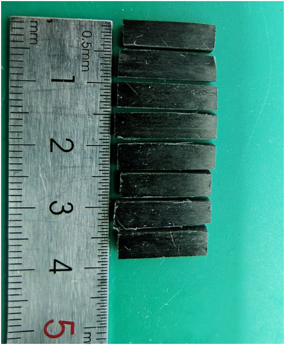
ILSS test sample.
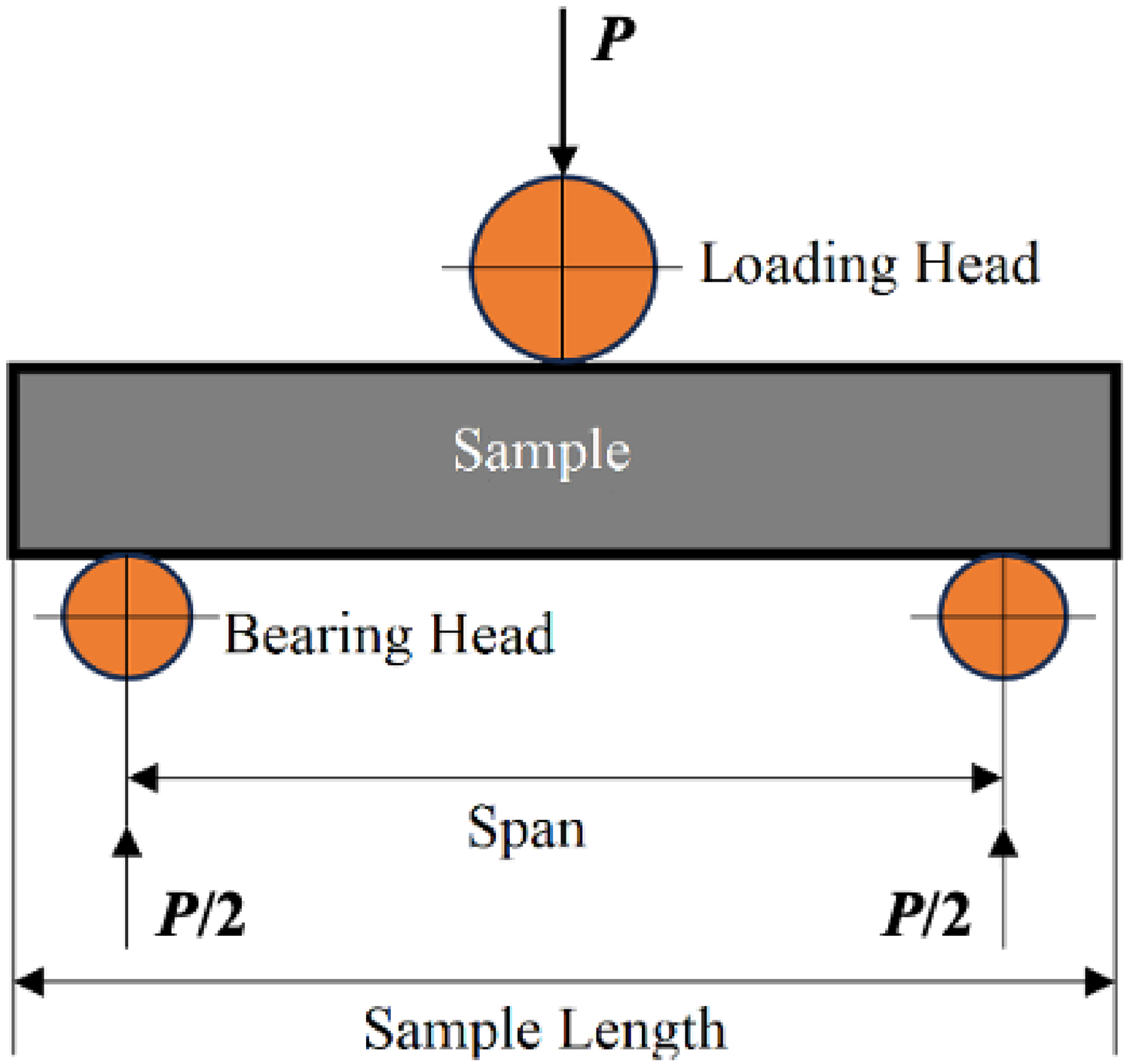
The principle of ILSS measurement by short beam method.
In the formula: Fs is the ILSS (MPa), Pm is the maximum load measured during the test (N), b is the measured value of the sample width (mm) and h is the measured value of the sample thickness (mm). Each group of samples was tested 5 times, and the average value was taken as the ILSS test value.
The porosity of CF/PEEK laminates was measured by the density measurement method according to the porosity test standard of reinforced plastics provided by ASTM D2734. The full-automatic true density and porosity analyser of Best Instrument Company was used for measurement. The porosity of the laminates can be calculated by the following formula:
The cross-sectional microstructure and fracture morphology of the specimens after grinding and polishing were observed by an Olympus confocal microscope.
LIG Raman spectroscopy characterisation
LIG was fabricated via an off-line process. The schematic diagram of its processing setup is shown in Figure 3(a), and the SEM image of LIG is shown in Figure 3(b).
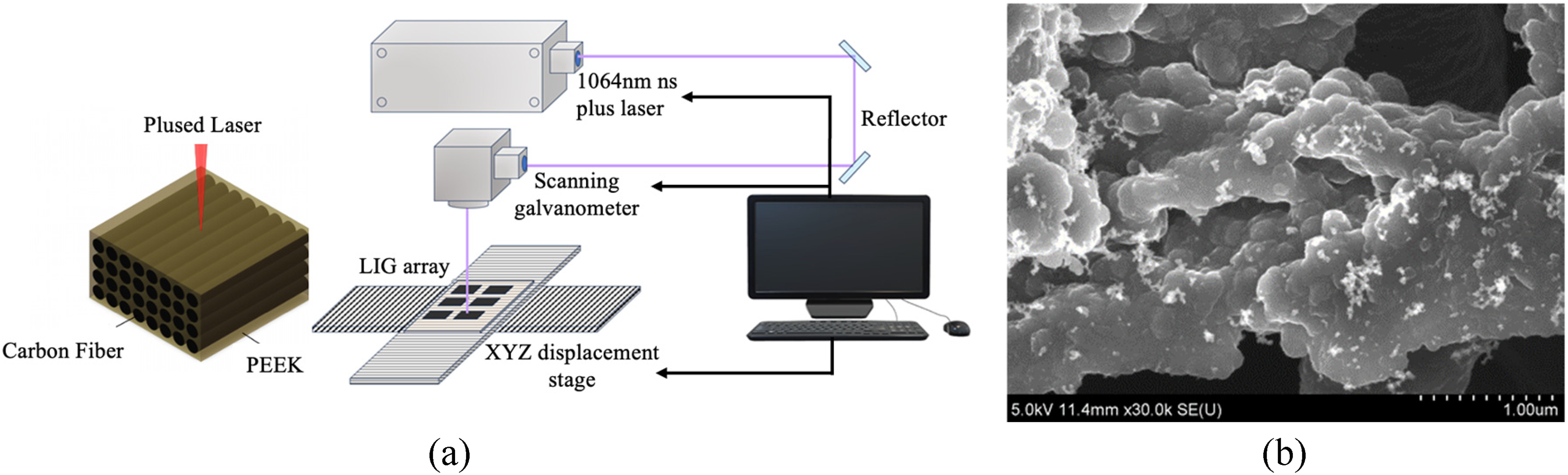
LIG preparation system and microstructure characterisation. (a) Schematic diagram of the off-line LIG preparation setup; (b) SEM image of LIG.
A nanosecond pulsed fibre laser with a wavelength of 1064 nm was used to scan the surface of the prepreg tapes. The scanning speed was 25 mm/s, which corresponds to the placement speed of the original CF/PEEK composite laser in-situ forming. The different pulsed laser parameters, such as power, repetition frequency, scanning spacing and defocusing distance, were adjusted to induce the formation of graphene on the smooth prepreg tape surface.
The Raman spectrum of graphene typically exhibits three characteristic peaks: the D peak around 1350 cm−1, the G peak around 1580 cm−1 and the 2D peak around 2680 cm−1. The D peak represents the lattice defects, and a higher value indicates more crystal defects in the carbon atoms. The G peak arises from the in-plane vibration of sp2 carbon atoms, which can effectively reflect the number of graphene layers. The 2D peak is a second-order Raman peak from two-phonon resonance, which is used to characterise the interlayer stacking mode of carbon atoms in the graphene samples. The number of graphene layers can be characterised by the ratio of I2D/IG, and a larger value indicates fewer layers (the I2D/IG of monolayer graphene is greater than 2). In addition, ID/IG can also be used to characterise carbon structure defects. The higher ID/IG represents the higher sp3/sp2 hybridisation ratio in the carbon structure. Figure 4(a)–(c) shows the Raman spectra of LIG induced by different laser parameters (pulse laser repetition frequency f, defocus distance δ, average power P) on the surface of prepreg tape by single factor method.
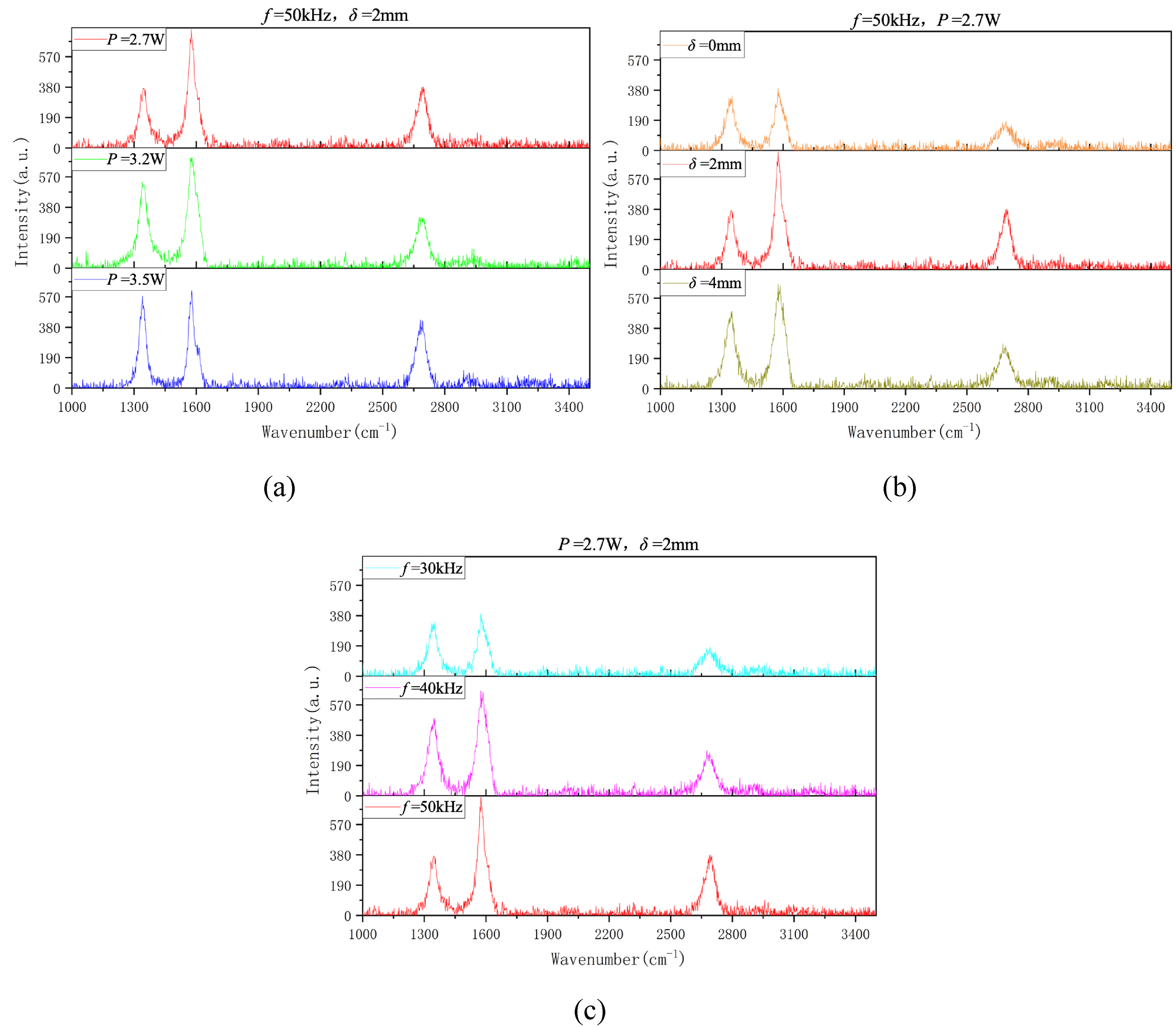
Trend of LIG Raman characteristic peaks. (a) Effect of laser power; (b) effect of defocus distance; (c) effect of repetition frequency.
It can be observed that the I2D/IG ratios for all samples are generally low, indicating that the LIG is a multilayer graphene structure. It can be seen from Figure 4(a) that with the increase of laser power, the G peak and 2D peak in the Raman spectrum of the sample do not change significantly, while the D peak increases significantly and becomes sharper. This indicates the formation of more defects in the samples, leading to an increase in the defect density or disordered structure due to the material damage caused by the increase in power. By observing Figure 4(b), it can be found that too high or too low defocusing distance will lead to an increase in the ID/IG value and more LIG defects. This is because a small defocus distance results in a small spot area and excessively high laser energy density, leading to material ablation. Conversely, a large defocus distance increases the spot size, and although the overlap rate increases, the power density decreases, preventing complete graphitisation. It can be seen from Figure 4(c) that as the repetition rate increases, the 2D peak becomes higher, and the ID/IG value also decreases significantly. This is because the high repetition rate directly determines the high overlap rate of the spot. With other parameters unchanged, the laser power density remains constant, and the distribution of laser energy on the material surface becomes more uniform. This uniform energy distribution helps to form a more uniform graphene structure, reduce defects and thus improve the quality of the LIG. When the laser power is 2.7 W, the repetition frequency is 50 kHz, and the defocus distance is 2 mm, the ID/IG value is the lowest, and the 2D peak is also sharper, indicating that this set of process parameters can be used to prepare LIG with lower defects and higher graphitisation degree on the PEEK surface. In the performance comparison experiment of laser in-situ forming samples of modified and unmodified composite materials, the relevant parameters of the pulsed laser are consistent with the parameters of this group.
Results and discussion
Effect of pulse spot spacing on the forming quality
The spot spacing on the prepreg tape surface is used to qualitatively describe the distribution density of LIG. Under constant conditions for other parameters, a larger spot spacing results in a sparser distribution of LIG, while a smaller spot spacing leads to a more concentrated distribution. Figure 5 shows the ILSS and porosity test results of the OC group and MC group of laminates at spot spacings of 0.6, 0.8, 1, 1.2, 1.4 and 1.6 mm, with a placement pressure of 400 N, a placement speed of 25 mm/s, and a heating temperature of 420 °C. MC-d1 represents the modified composite with a laser spot spacing of 1 mm.
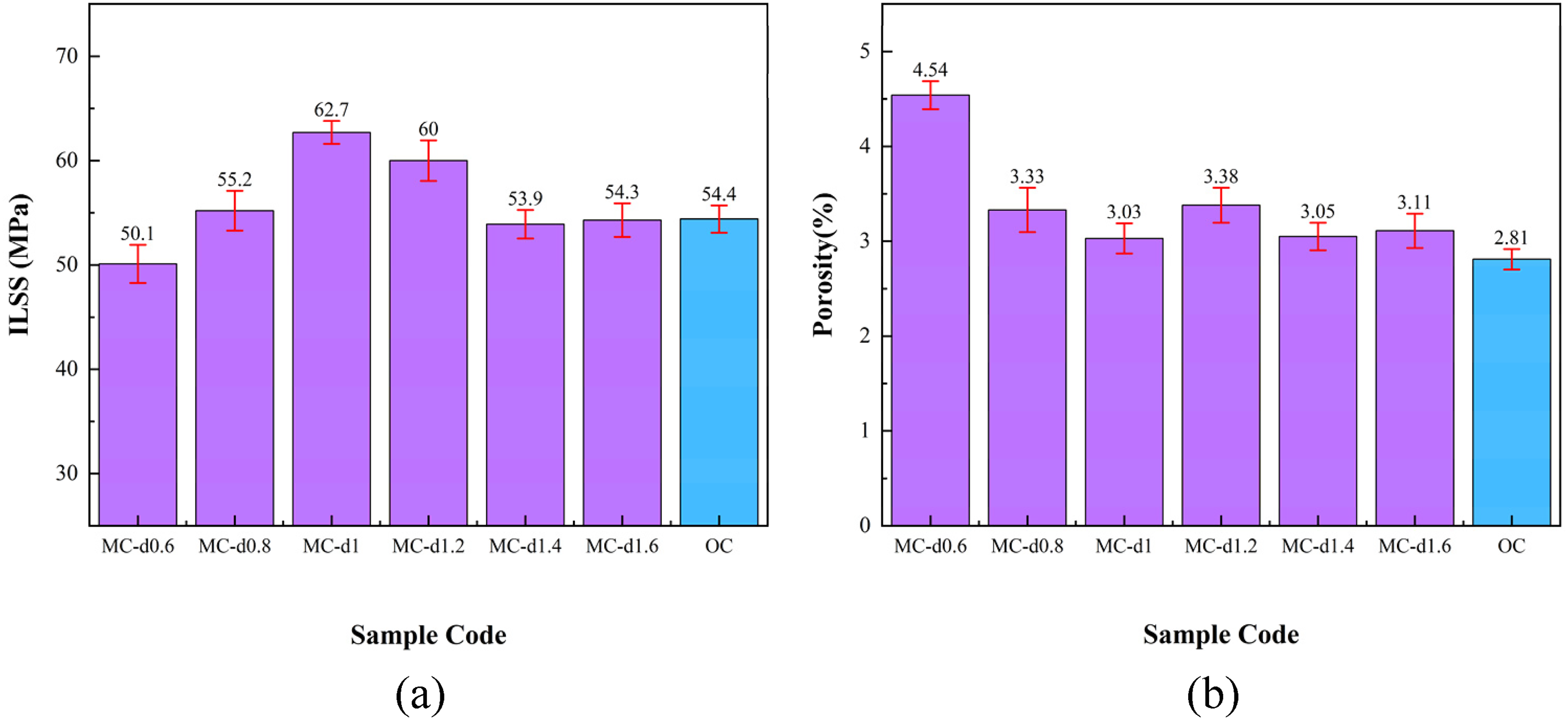
ILSS and porosity of CF/PEEK laminates at different spot spacings. (a) ILSS; (b) porosity.
It can be seen from Figure 5(a) that when the pulse laser spot spacing is 0.8, 1, 1.2 mm, the ILSS of the MC group sample is significantly higher than that of the control group OC sample. The MC-d1 sample with a spot spacing of 1 mm exhibited the highest interlaminar ILSS, reaching 62.7 MPa, which is approximately 15% higher than that of the OC sample (54.4 MPa). This 15% increase in ILSS is a substantial and meaningful improvement for engineering applications, as it directly elevates the shear-bearing capacity of CF/PEEK laminates, effectively retarding interlaminar crack initiation and propagation under shear, bending and impact loads and thus significantly enhancing the structural reliability and service life of laser in-situ formed composite components in high-performance load-bearing scenarios. This indicates that LIG can significantly improve the interlayer strength of CF/PEEK under appropriate pulsed laser parameters. When the pulse spot spacing is 0.6 mm, the ILSS value of the MC sample is the lowest and significantly lower than that of the OC sample. Combined with the cross-sectional microscopic morphology results of MC-d0.6 in Figure 6, the dense spot spacing causes obvious ablation of the prepreg tape surface, which is directly observed as a large number of exposed fibres and reduced local resin content in the laser-irradiated area; during the forming process, the molten resin in the surrounding area cannot fully infiltrate these exposed fibres, and the ablation-induced increase in surface roughness, which was quantitatively measured using a Laser Scanning Confocal Microscope (LSCM, Model: OLS5100, Olympus Corporation, Japan), further reduces the intimate contact degree between laminate layers, leading to poor interlayer bonding. In addition, microstructure characterisation reveals that the concentrated LIG distribution in the ablated area induces agglomeration in the resin matrix, which forms stress concentration zones and further reduces the ILSS of the sample. In addition, the concentrated LIG distribution in the ablated area is observed to cause agglomeration in the resin matrix through microstructure characterisation, which forms stress concentration zones and further reduces the ILSS of the sample. It can be seen from Figure 6(b) that the porosity of the MC samples is slightly higher than that of the OC samples when the spot spacing is 0.8, 1, 1.2, 1.4 and 1.6 mm. The porosity of MC-d1 is 3.03%, which is 7.8% higher than that of the OC samples. When the spot spacing is 0.6 mm, the porosity increases significantly. Figure 6 clearly shows that the MC-d0.6 sample has more and larger interlayer pores, which is direct evidence that the fibre exposure and insufficient resin infiltration caused by excessive laser ablation lead to incomplete filling of the interlayer space during forming, resulting in a significant increase in pore volume and porosity.

Microscopic morphology of cross-sections of samples MC-d0.6 and MC-d1 with 20× magnification (pores in the red frame). (a) MC-d0.6; (b)MC-d1.
Figure 6 shows the magnified cross-sectional microstructure of the samples, and the MC-d0.6 sample has more and larger interlayer pores, which is the key reason for its significant porosity increase.
Figures 7 and 8 are the fracture morphologies of the OC and MC-d1 samples, respectively. Direct observation from the fracture morphology shows that the crack surface of the OC sample is smooth and flat, while the crack surface of the MC-d1 sample is significantly rougher with obvious tearing and bridging features. This is because when the interlayer fracture failure occurs, the resin matrix is destroyed, and the LIG infiltrated into the matrix hinders crack propagation through a bridging effect and energy dissipation during its pull-out process. This is an important factor in the improvement of ILSS. The principle of LIG's interlayer reinforcement modification of CF/PEEK laminates is shown in Figure 9. After the pulsed laser induces LIG formation on the prepreg tape surface, the PEEK is not yet melted, and LIG is not dispersed in the interlayer. LIG particles are concentrated in the irradiated areas. When the prepreg tape is transmitted to the continuous laser heating zone, the resin begins to melt upon heating. With the increase of temperature, the viscosity of the PEEK resin decreases significantly. The pressure of the roller promotes the accelerated flow of the resin. Through the characterisation of the distribution of LIG in the interlayer of the moulded laminate, it is confirmed that LIG fully penetrates the resin matrix and disperses uniformly into the interlayer with the resin flow under the combined action of heating and pressure, finally forming CF/PEEK laminates with uniformly distributed LIG between layers. At this point, LIG particles can play a role in stress transfer in the interlayer resin-rich region, which enhances the interlayer bearing capacity of the laminates. Moreover, when the laminates produce interlaminar cracks under load, the crack propagation causes the LIG to be pulled out from the matrix. This process will increase the energy consumption, thus hindering the development of cracks, and the laminates are thus strengthened.
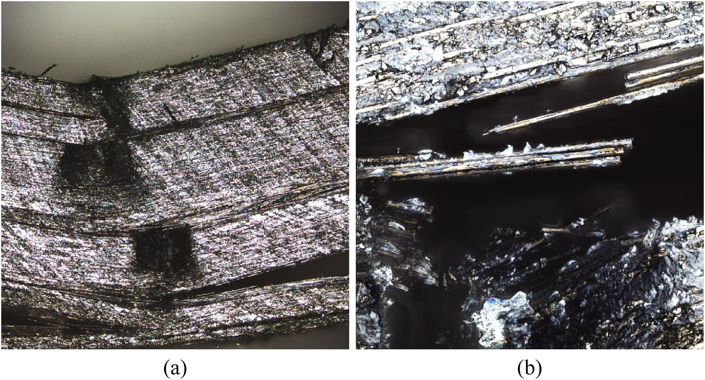
Fracture morphology of OC samples. (a) 10×; (b) 50×.
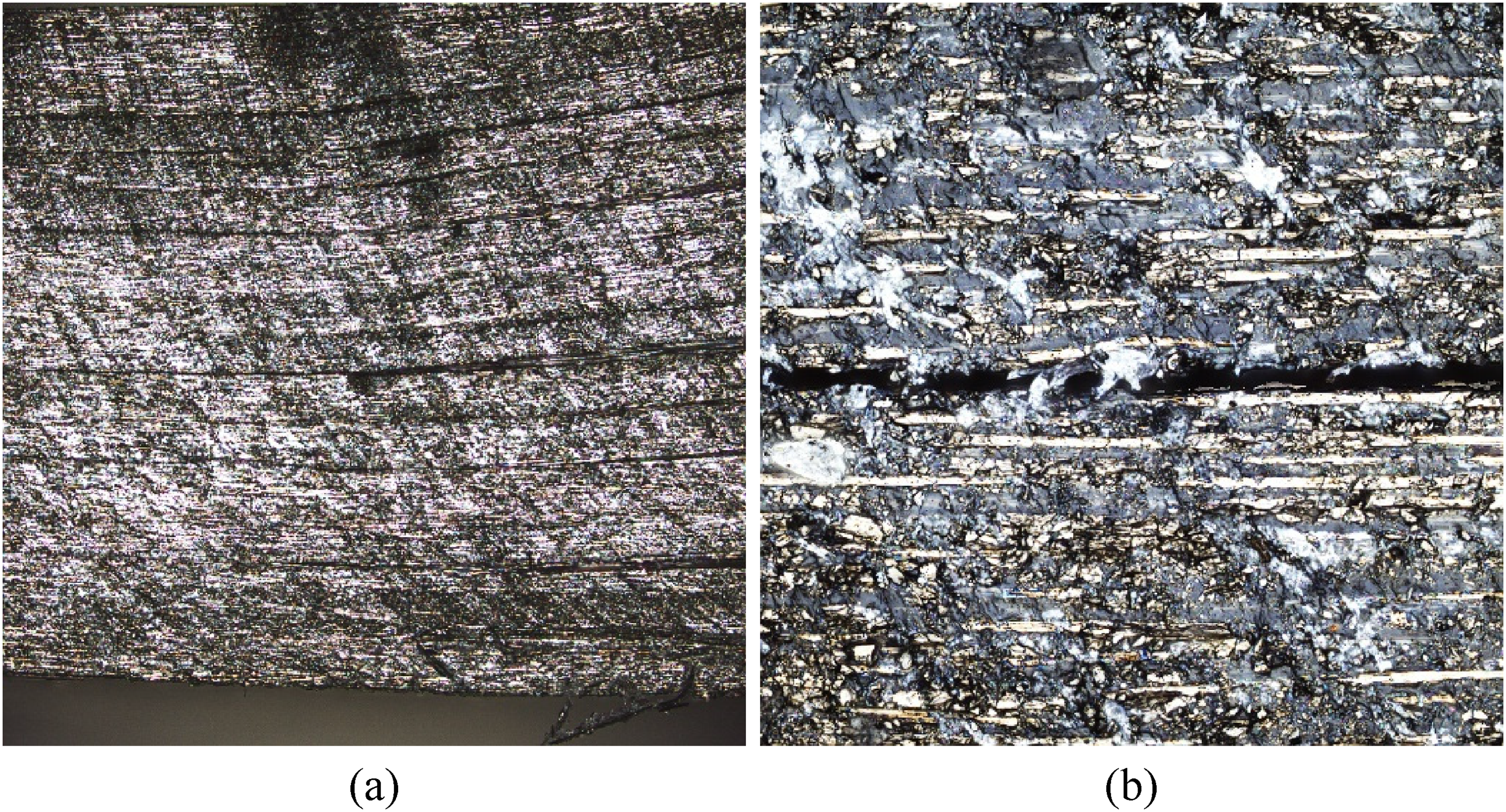
Fracture morphology of MC-d1 sample. (a) 10×; (b) 50×.
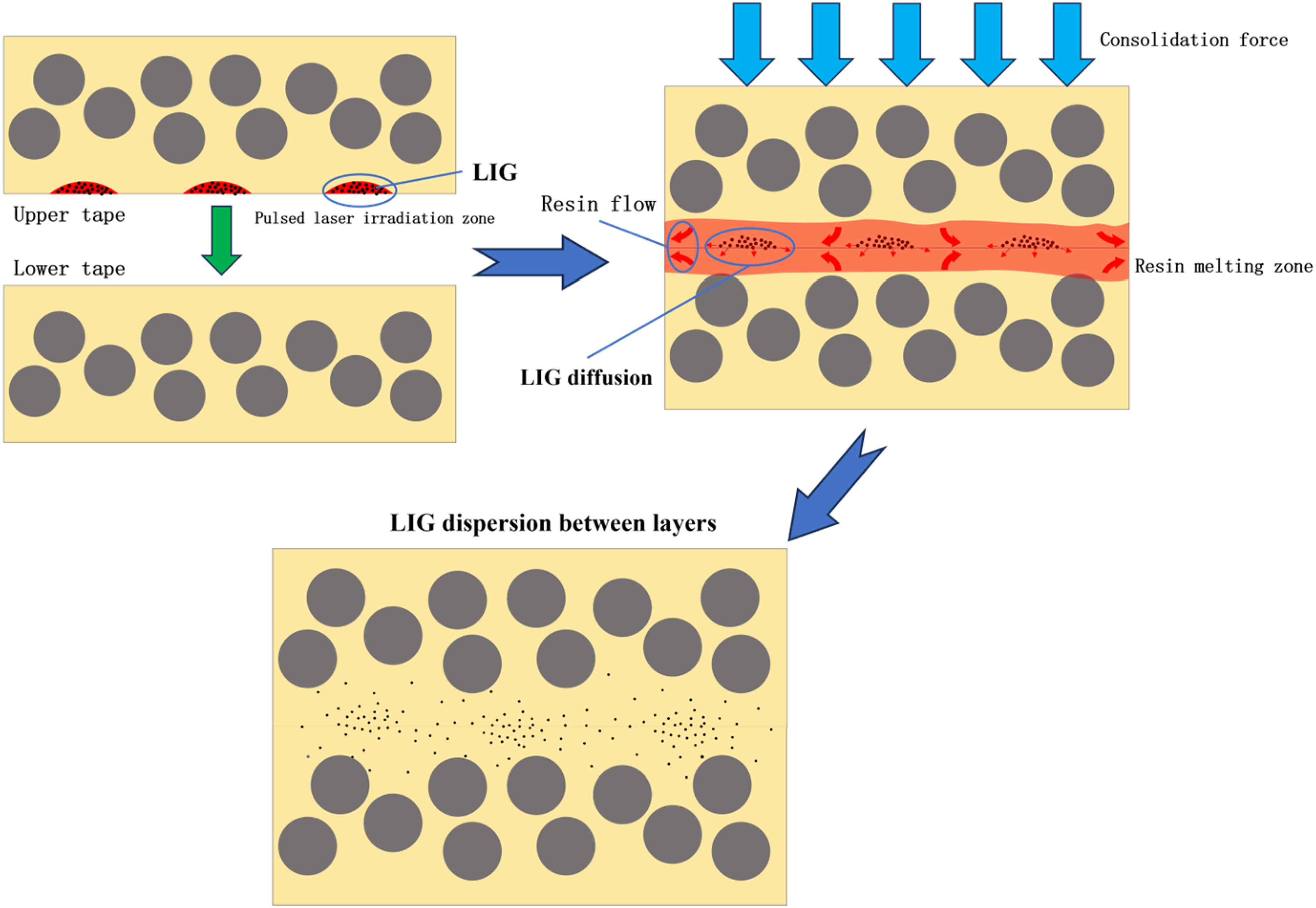
Principle of LIG interlayer reinforcement modification.
Effect of heating temperature on the forming quality
Figure 10 is the test results of ILSS and porosity for CF/PEEK laminates in MC and OC groups at different continuous laser heating temperatures, with a placement pressure of 400 N, a placement speed of 25 mm/s and a spot spacing of 1 mm.
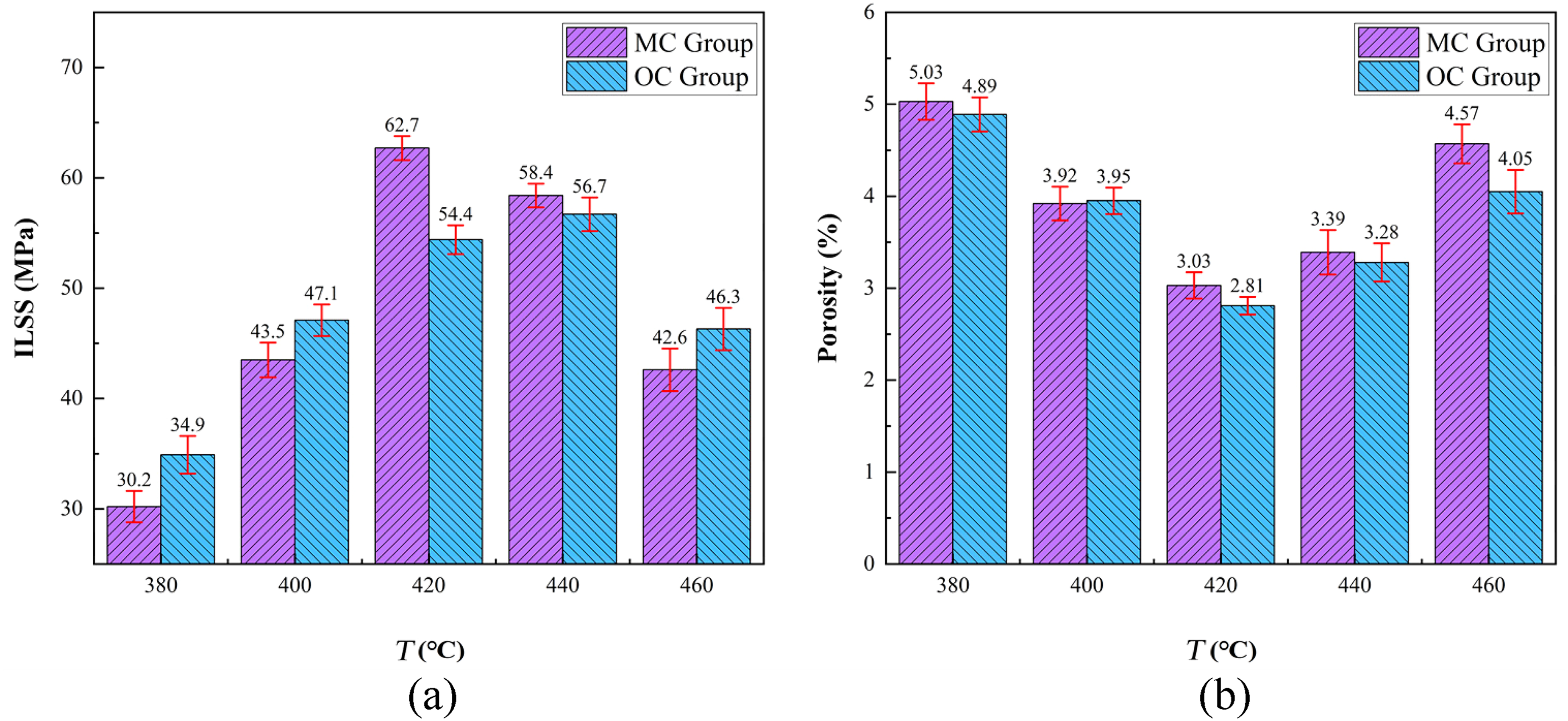
ILSS and porosity of CF/PEEK laminates at different heating temperatures. (a) ILSS; (b) porosity.
From Figure 10(a), the ILSS of the two moulding samples increased first and then decreased with the increase of heating temperature. When the heating temperature was higher, the ILSS of the MC group decreased faster. Combined with the rheological characteristics of PEEK resin and interlayer microstructure characterisation results, increasing the heating temperature within a certain range can effectively reduce the resin viscosity, enhance the movement of polymer chains and realise full diffusion and fusion at the interlayer interface, which is observed as a blurred interlayer interface and improved interlayer adhesion quality in the microstructure. For the MC group samples, pulsed laser irradiation has caused a small amount of PEEK ablation and local resin content reduction on the prepreg surface; when the heating temperature exceeds 440 °C, the pyrolysis of PEEK resin is directly observed through the appearance and microstructure of the sample (such as carbonisation and microcracks in the interlayer), which further reduces the local resin content between layers and leads to a significant decrease in the bonding quality of the upper and lower layers and ILSS. In addition, it was observed that the MC group samples showed higher ILSS than the OC group samples at T = 420 °C and T = 440 °C, while no enhancement effect was observed in other cases. Microstructure characterisation of MC group samples at low temperatures (380 °C, 400 °C) shows that the high viscosity of the resin leads to the failure of LIG to disperse uniformly between layers, and obvious LIG agglomeration is observed, which forms stress concentration zones and reduces the interlayer bearing capacity, which is the direct reason for the loss of LIG reinforcement effect at low temperatures.
It can be seen from Figure 10(b) that the porosity of the two groups of samples decreases first and then increases with the increase of heating temperature. This trend is consistent with the change of resin rheological properties and pore discharge state observed by microstructure characterisation: appropriate increase of heating temperature reduces resin viscosity and improves its rheological properties, which is conducive to the discharge of interlayer gas during the forming process, and the microstructure shows a significant reduction in the number and volume of interlayer pores; when the heating temperature is too high, the rapid volatilisation of small molecules in the resin and the rebound expansion of un-discharged pores are observed in the microstructure, which leads to the increase of pore volume and porosity. In addition, it was also observed that when the heating temperature was 460 °C, the porosity of the MC group sample was significantly higher than that of the OC group sample, while the difference in porosity was not significant in other cases. Figures 11 and 12 clearly show that the MC-T460 sample has a large number of interlayer pores with larger volume; this is due to the superposition of local resin content reduction caused by pulsed laser ablation and excessive resin pyrolysis at high temperature, which leads to insufficient resin filling between layers and more interlayer pores, thus significantly increasing the porosity.

Microscopic morphology of the cross-section of the OC-T400 sample. (a) 20× (red frame is pore, green frame is crack) (b) 50× magnification of the crack area.

Microscopic morphology of cross-section of MC-T460 sample. (a) 20× (red frame is pore); (b) 50× magnification of the pore area.
It can be seen from Figure 11 that a small number of cracks appear between the layers of the OC-T400 sample, which is the performance of the poor bonding quality between the layers. Microstructure and resin rheology test results show that at 400 °C, the resin fluidity is poor, the molecular chain diffusion degree is low, and the close contact degree between the upper and lower layers is low during the forming process, which directly forms interlayer cracks; when subjected to load, these pre-existing interlayer cracks will expand rapidly, resulting in delamination failure of laminates. It is observed in Figure 12 that the MC-T460 sample has more and larger interlayer pores, which verifies the reason for the significant increase in porosity of the sample described above.
Effect of placement pressure on the forming quality
Figure 13 shows the test results of ILSS and porosity for MC and OC samples at different placement pressures, with a heating temperature of 420 °C, a placement speed of 25 mm/s and a pulsed laser spot spacing of 1 mm. It can be observed that the placement pressure has a very similar effect on the forming quality of both groups of samples. As the placement pressure increases, the ILSS of all samples shows an increasing trend, while the porosity shows a decreasing trend. Combined with the cross-sectional microstructure characterisation of samples at different pressures (Figure 14), the increase of placement pressure is directly observed to effectively improve the intimate contact between laminate layers; for the high-viscosity PEEK resin, the increase of pressure promotes the flow of molten resin and sufficient infiltration of carbon fibres, which is reflected in the microstructure as a blurred interlayer interface and improved interlayer bonding quality. However, when the placement pressure is too high (500 N), a slight decrease in ILSS and a corresponding increase in porosity are observed for both groups of samples. Microstructure observation shows that excessive placement pressure causes partial damage to the carbon fibre structure and excessive extrusion of the interlayer molten resin to both sides, resulting in local resin deficiency between layers and a slight decrease in bonding quality, which is the direct cause of the slight change in ILSS and porosity at high pressure. In addition, the comparison shows that under all placement pressures, the ILSS values of the MC group samples are generally higher than those of the OC group samples, and the uniform distribution of LIG between layers is observed in the microstructure of MC group samples at all pressure levels, which indicates that LIG can exert a stable strengthening effect on the laminates at different placement pressures through stress transfer and crack resistance.
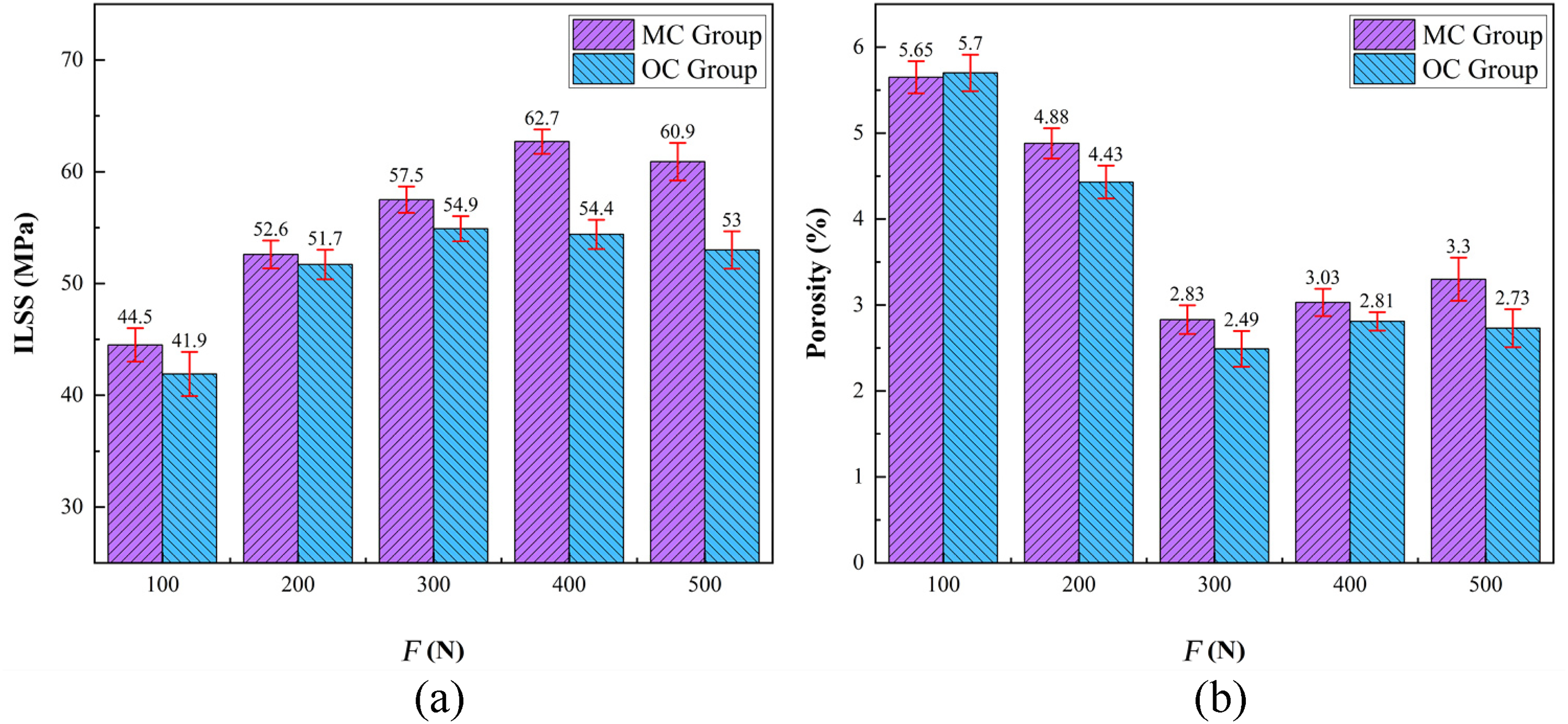
ILSS and porosity of CF/PEEK laminates at different placement pressures. (a) ILSS; (b) porosity.

Microscopic morphology of sample cross-sections with 10× magnification at different placement pressures (red frame is pore). (a) MC-F100; (b) MC-F200; (c) MC-F300.
It can be seen from Figure 14 that when the placement pressure is 100 N, the interlayer interface of the sample is relatively clear, with numerous pores and a small amount of delamination. The ILSS is relatively low at this point. With the significant increase of placement pressure (200 N, 300 N), the microstructure clearly shows that the resin flow is accelerated during forming, which promotes the discharge of residual gas in the material, the fibre infiltration is more sufficient, the interlayer interface gradually becomes blurred, the interlayer adhesion quality is improved and the pore distribution is significantly reduced, which directly leads to the increase of ILSS. This fully demonstrates that the appropriate increase of the placement pressure has a positive impact on the improvement of interlayer bonding quality and the reduction of pores.
Conclusion
This study proposed interlayer reinforcement modification of CF/PEEK prepreg tapes by LIG, with ILSS and porosity as the core evaluation indices, to optimise the mechanical properties of laser in-situ formed composites. We systematically investigated the effects of pulsed laser spot spacing, heating temperature and placement pressure on the forming quality of LIG-modified (MC group) and unmodified (OC group) CF/PEEK laminates, and clarified the interlayer reinforcement mechanism of LIG. The results showed that a spot spacing of 1 mm was optimal, under which the ILSS of the MC group was maximally improved by 15% (from 54.4 to 62.7 MPa) with only a slight increase in porosity (from 2.81% to 3.03%). LIG exerted an effective reinforcement effect only at 420–440 °C and maintained stable enhancement within the placement pressure range of 100–500 N. The in-situ LIG construction method on the surface of CF/PEEK prepreg tapes developed in this study enables efficient interlayer modification. LIG alleviates interlayer delamination through stress transfer and energy dissipation during crack propagation, providing a simple and controllable technical approach for fabricating CF/PEEK components with high interlayer strength and promoting the engineering application of laser in-situ forming technology.
Footnotes

Funding
The authors received no financial support for the research, authorship, and/or publication of this article.
Declaration of conflicting interests
The authors declared no potential conflicts of interest with respect to the research, authorship, and/or publication of this article.