
Abstract
Decarbonising the heavy-duty sector requires concepts that surpass the diesel cycle in efficiency while meeting increasingly stringent emissions standards. The recuperated split-cycle engine (RSCE) offers a potential pathway, combining quasi-isothermal compression (enabled with secondary working fluids, SWF) with internal exhaust heat recuperation. This work assesses hydrogen-diesel dual fuelling using single-cylinder RSCE experiments at a range of loads, supported by a validated Chemkin-Pro framework. The modelling extended the analysis using a reactor network and multizone model to evaluate high-load conditions, pre-ignition mixing and SWF carry-over. Experiments show stable dual-fuel operation, with light and controllable pre-ignition linked to elevated HO2/H2O2/OH radicals. Model predictions at higher load indicate that, relative to a neat diesel baseline, BMEP is predicted to be maintained, with BSFC and CO2 reduced by 33% and 43% at 10%Vol H2. NOx is predicted to decrease by 23% at 5%Vol H2, but to increase by 42% at 10%Vol H2, as the H2 energy share approaches 40%, consistent with faster premixed heat release and elevated O/OH driving thermal-NO. With efficient aftertreatment conversion, the 5%Vol case is predicted to meet 0.2 g/kWh NOx, whilst 10%Vol remains within the 0.26 g/kWh on-road benchmark. Furthermore, the model predicts that adding H2O to the charge (SWF carry-over) could reduce NOx by 30% at 0.10% H2O with a 3% BMEP penalty alongside an increase in HC due to temperature-limited oxidation. This combined experimental demonstration of expander port-injected H2 in an RSCE, supported by a physically informed spatially resolved multizone modelling framework, supports the combustion feasibility for hydrogen-diesel dual fuelling and identifies the calibration and hardware levers required to achieve practical impact for Euro 7-class NOx alongside EU CO2 reductions. Overall, these results position RSCE + H2 as a potential mid-term route towards sustainable heavy-duty propulsion.
Keywords
Introduction
Decarbonisation context
The motivation behind this research is to address the urgent need for sustainable, decarbonised propulsion systems that retain the reliability and energy density required by sectors like heavy-duty and maritime. 1 Sustainability is increasingly supported by legislation, necessitating strategies that meet regulatory targets, one of the most stringent being the European Commission’s requirement for a 30% CO2 reduction from 2025 to 2030,2,3] with emerging Euro 7 targets of approximately 0.26 g/kW NOx and 0.755 g/kWh hydrocarbon (HC).4,5 While diesel particulate filters (DPF) and selective catalytic reduction (SCR) can significantly reduce emissions (90% and 95%4,6,7), optimising fuel and engine performance remains crucial, particularly for duty cycles where other zero-emission options may be constrained.
Hydrogen has received growing attention as a zero-carbon fuel for internal combustion engines, driven by its potential to eliminate fuel-carbon CO2 emissions at the point of use. While the life-cycle greenhouse-gas intensity of hydrogen can vary substantially depending on upstream production routes, carrier choice, and transport logistics, 8 the feasibility of hydrogen deployment in existing and emerging engine architectures ultimately depends on achieving stable, efficient, and emissions-compliant combustion under realistic operating conditions.
Compared to diesel, hydrogen’s markedly different fluid-kinetic properties introduce unique operational challenges. Investigations of direct-injection hydrogen engines report practical development issues such as Coandă-driven spray behaviour and mixture control, 9 whilst previous work highlights the importance of jet geometry and plume–wall interaction for achieving near-zero emissions with high thermal efficiency. 10 Risks of pre-ignition and backfire have been a recurring focus, with both CFD and experimental analyses of surface ignition, 11 and studies on cylinder-to-cylinder variation at different engine speeds. 12 In parallel, recent combustion system development for heavy-duty hydrogen engines has demonstrated that piston optimisation can avoid knock and pre-ignition, pointing to promising design pathways. 13 Its high adiabatic flame temperature can elevate thermal NOx, however, lean operation increases mixture specific heat and has been shown to improve efficiency while reducing NOx in Spark-Ignition (SI) H2 engines. 14
These findings provide valuable insights but are derived entirely from conventional engine architectures—principally SI and compression-ignition (CI) platforms adapted for gaseous hydrogen fuelling. Dual-fuel concepts (diesel–H2, methane–H2) have also been trialled in conventional layouts,15,16 again demonstrating both potential efficiency gains and challenges with knock, volumetric displacement, and emissions. However, there remains little published work addressing hydrogen fuelling within alternative engine concepts. In particular, the split-cycle engine offers fundamentally different thermodynamic conditions due to decoupled compression and expansion, quasi-isothermal operation, and integrated recuperation. Taken together, these features may offer higher overall conversion efficiency. Hence, this study focuses on the decarbonisation and cleaner air potential of hydrogen-diesel dual fuelling in a recuperated split cycle engine (RSCE).
Recuperated split-cycle engine concept
Figure 1 illustrates the RSCE concept and, Figure 2, its implementation within the single-cylinder research engine (SCRE). The RSCE17–19 differs fundamentally from conventional compression and spark-ignition engines by decoupling compression and expansion into separate cylinders, which are mechanically coupled via a common crankshaft operating with a phase shift. Charge transfer between the cylinders is governed by valve timing, with the exhaust valve closing (EVC) of the compression cylinder and the intake valve opening (IVO) of the expansion cylinder phased to regulate transfer pressure and flow. In the SCRE implementation, valve timing can be adjusted to control charge conditions and combustion phasing within the expansion cylinder.
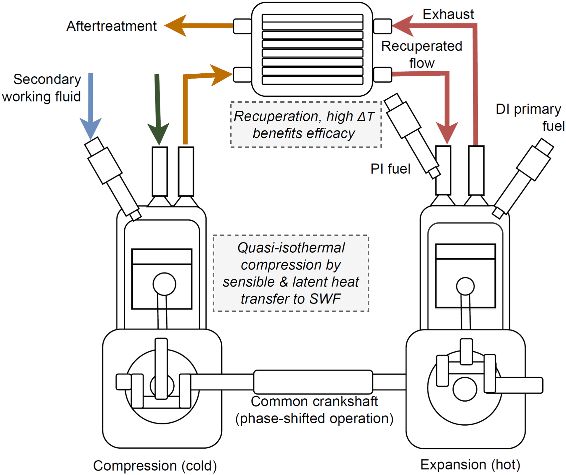
Schematic representation of the recuperated split-cycle engine (RSCE) with SWF injection in the compression cylinder and H2 injection in the port of the expander cylinder.
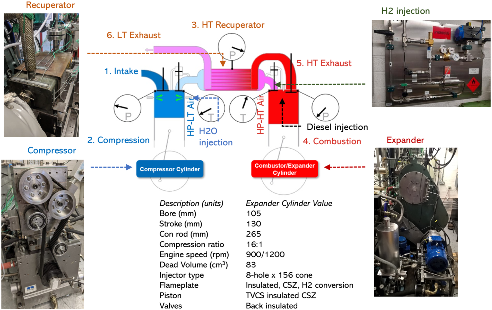
Testing set-up with compressor, expander, recuperator and port H2 injection in the expander hardware relating to the recuperated split cycle and expander engine specifications.
Air is compressed in the cold compression cylinder under quasi-isothermal conditions, achieved through sensible and, where phase change occurs, latent heat transfer to a secondary working fluid (SWF). This suppresses the temperature rise during compression, reducing compression work (17% reduction depending on flow and fluid 20 ). This also increases the temperature difference between compressed air and exhaust gas, thereby enhancing recuperation of exhaust exergy.21,22 Both water and liquid nitrogen have been explored as SWFs, 20 each presenting trade-offs between cooling effectiveness and system complexity.
The compressed charge is then transferred through a recuperator, where it is heated using exhaust gas energy before entering the hot expansion cylinder for combustion and work extraction. Optimised RSCE configurations integrating quasi-isothermal compression and exhaust gas recuperation have been suggested to achieve up to 24% BSFC reduction relative to conventional cycles. 20 In addition, prior studies suggest that the high-pressure-ratio intake process into the expansion cylinder may generate high-velocity flow, with local transonic conditions near the valve. 23 These conditions may enhance in-cylinder mixing and atomisation; however, they also introduce complex valve-flow dynamics and potential flow restrictions, and may increase pumping losses if not carefully managed. As such, the net benefit depends on the detailed transfer and combustion strategy.
Prior work has also demonstrated the potential of the RSCE for ultra-low NOx emissions and high indicated thermal efficiency (ITE), with the STEPCO2 project indicating efficiency–emissions benefits and the RE-ARMD project 24 delivering the first part-hydrogen fuelled RSCE prototype.
Split cycle research gap
Compared to the conventional cycle, the RSCE offers improved thermal management and exergy efficiency by moderating entropy build-up during compression and recovering energy during the transfer phase. Hence, this combination of features positions the RSCE as a promising solution for reducing emissions while maintaining the necessary power and efficiency for heavy-duty systems.
While previous studies have explored hydrogen fuelling in conventional engines, theoretical RSCE cycles and neat diesel RSCE’s, 19 there has been limited experimental demonstration of part-hydrogen fuelling in RSCE prototypes. Moreover, existing RSCE simulation approaches typically rely on uniform or geometrically distributed heat-loss correlations. 25 This constrains predictive fidelity under multiphase dual-fuelling operation involving both gaseous (port-injected) and liquid (direct-injected) fuels, where in-cylinder stratification strongly influences ignition behaviour. In contrast, the present work incorporates a stratified multizone framework, calibrated and validated against experimental RSCE data, to provide more physically grounded predictions.
Contribution of the study
The originality of this work lies in experimentally demonstrating part-hydrogen fuelling within an RSCE platform and evaluating its feasibility for meeting future on-road heavy-duty emissions targets (e.g. Euro 7 NOx limits) through a hybrid modelling framework. Experimental data from the SCRE was collected across ∼46% of a representative heavy-duty drive cycle and extended using Chemkin-Pro multizone simulations, including the effects of hydrogen pre-ignition chemistry and water addition—representing its use during quasi-isothermal compression. This study builds on earlier RSCE analyses 26 by adding new validation points, refined chemical modelling, and a physically informed theoretical perspective for simulation modelling of hydrogen–diesel dual-fuel operation.
Hence, this paper makes the following key contributions:
Experimental demonstration of hydrogen-diesel dual fuelling in an RSCE.
Implementation of a physically informed zonal distribution, incorporating volume fraction, mass stratification, and a Gaussian-weighted heat-loss treatment within the Chemkin MZ framework to represent radial thermochemical and heat transfer behaviour.
Integrated experiment–simulation framework, validated against SCRE data, achieving close agreement in in-cylinder performance and emissions.
Evaluation of hydrogen fuelling strategies against on-road heavy-duty NOx (≈0.2–0.26 g/kWh) and CO2 benchmarks, highlighting efficiency–emissions trade-offs.
Scope of the study
This analysis is framed around on-road heavy-duty engine applications (e.g. trucks), combining experimental data from the SCRE with calibrated Chemkin-Pro MZ simulations. The study focuses on port-injected hydrogen substitution across representative heavy-duty drive-cycle conditions (900/1200 rpm, 1.3–9.4 bar BMEP), with emphasis on combustion feasibility and emissions compliance as the most immediate technical considerations for hydrogen fuelling. Aftertreatment optimisation, full-system integration, and broader cost or safety considerations are beyond the present scope.
While the RSCE architecture offers multiple interacting optimisation pathways (e.g. secondary working fluid flow rate, thermal management, and charge conditioning), this study isolates hydrogen substitution as the primary variable to enable controlled assessment of combustion behaviour and emissions response. Experiments were conducted up to 23%Vol H2 to characterise combustion limits, while simulation focused on ≤11%Vol H2 and extended the analysis to higher-load conditions using a combined experimental and Chemkin-Pro RNM→MZ modelling framework.
Specifically, this work aims to:
(i) Quantify the effects of H2 substitution on stability, phasing, NOx, HC and CO2 at 900/1200 rpm and 1.3→9.4 bar BMEP;
(ii) Identify the onset and character of pre-ignition and delineate hardware/calibration constraints for dual-fuel operation; and
(iii) Extend experimental partial hydrogen fuelling to higher-load and quasi-isothermal (SWF) cases via simulation to assess feasibility beyond the experimentally tested range.
Evaluation criteria include establishing experimental repeatability from 100-cycle statistics (mean, SD, CI, CoV) and model–experiment agreement for BMEP, NOx, CO2, and fuel/energy rates within typical engine-simulation uncertainty bounds; mechanistic consistency between RNM species trends (pre-ignition radicals) and observed ignition signatures.
Materials and methodology
This study investigates partial hydrogen substitution in the RSCE using a combined experimental–simulation framework:
Experiments: SCRE operation at 900 and 1200 rpm, across low-, mid-, and high-load conditions (LL, ML, HL 1.3→9.4 bar BMEP), including baseline diesel and diesel with port-injected hydrogen (3.5→23%Vol in air). The extended range was used to characterise combustion behaviour and identify practical limits. These test points correspond to some of the most time-intensive regions of a representative heavy-duty drive cycle and ensure high relevance to regulatory and practical performance assessments.
Simulations: Chemkin-Pro Reactor Network Model (RNM) to capture radical chemistry during pre-ignition mixing in the expansion cylinder, followed by a Multizone (MZ) engine model to extend analysis to higher-load operation with 5 and 10%Vol H2 substitution, consistent with the primary analysis window.
Quasi-isothermal compression: The case includes water addition to the expander intake charge to evaluate the effect of this SWF on combustion performance.
The analysis focuses on CO2 reduction, combustion stability, HC emissions, and NOx formation—parameters that define the main efficiency–emissions trade-offs under hydrogen fuelling.
Table 1 lists the exact operating set-points and the H2O fraction used in simulated cases. The speed–BMEP bins together cover ∼46% of the time-weighted share of a representative heavy-duty duty cycle, estimated by mapping the bins onto the published speed–load distribution from work by Ricardo. 27 Following sections provide details of the experimental and simulation methodologies. High-load Diesel+H2 points were explored in simulation only using the MZ model; in these simulations, H2O was added to the expander intake mixture to emulate a SWF under quasi-isothermal compression—this charge conditioning was not available with the experimental results.
Test matrix for SCRE experiments and simulation runs.
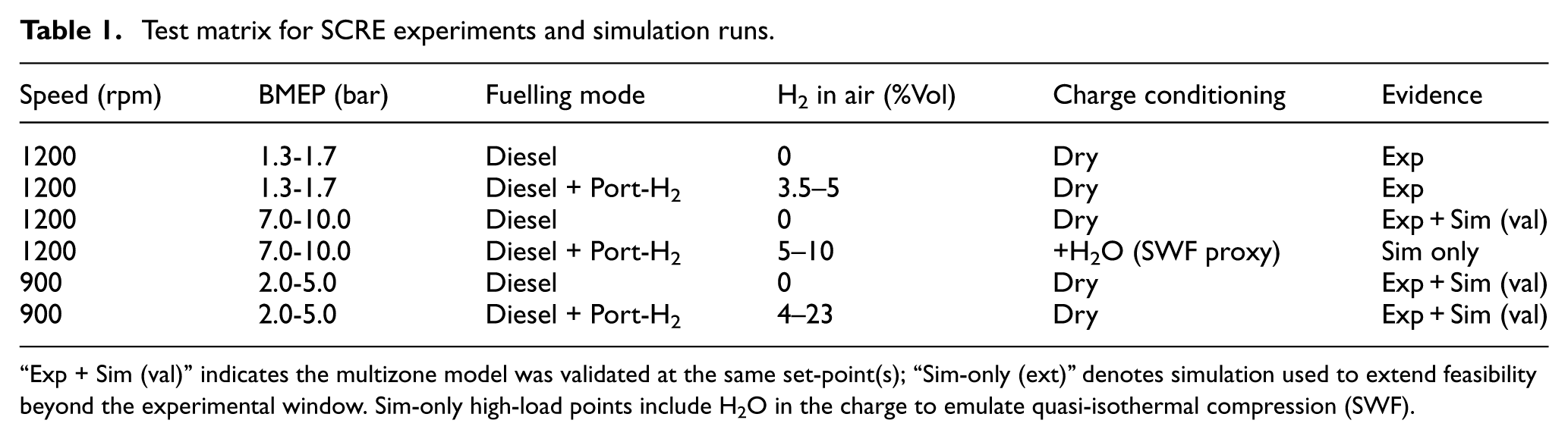
“Exp + Sim (val)” indicates the multizone model was validated at the same set-point(s); “Sim-only (ext)” denotes simulation used to extend feasibility beyond the experimental window. Sim-only high-load points include H2O in the charge to emulate quasi-isothermal compression (SWF).
Experimental split cycle engine
Figure 2 illustrates the subsystem layouts related to SCRE hardware, including the compression cylinder, internal recuperator, hydrogen port fuel delivery in the expander intake, and the expansion cylinder. The SCRE was operated under controlled steady-state conditions–an established approach for early-stage combustion and emissions research. This configuration enables precise control of boundary conditions and repeatable measurements, making it well-suited for exploring alternative fuels and injection strategies before full engine integration. The SCRE setup reflects standard validation methodology, supporting detailed investigation of port-injected hydrogen combustion under quasi-steady conditions. While future work should address scale-up considerations—including transient full-cycle validation—this study focuses on in-cylinder behaviour, ignition stability, and emissions characteristics.
Although dynamic and transient emissions mapping were beyond the scope of this work, the considered speed-load points (900 and 1200 rpm across 1.5 to 9.4 bar BMEP) span a noticeable portion of a typical heavy-duty drive cycle based on time-weighted usage. This ensures that the results remain applicable to real-world engine operation, particularly under conditions of highest regulatory and practical importance.
Baseline experiments used diesel-only fuelling to establish reference conditions. Stable operation was achieved within an 18–20 bar expander intake pressure range; lower pressures resulted in spray impingement and poor combustion. Injector control was provided via a National Instruments system replacing the original Emtronics unit, allowing independent control of diesel and hydrogen injection. A Delphi DI-CNG injector (16 bar rating) was adapted for hydrogen fuelling, fitted alongside the diesel injector for pilot operation. The injector delivered hydrogen between expander exhaust valve closing (EVC) and intake valve opening (IVO). This injection period was extended to 15–25°CA to exploit low-pressure conditions, with intake pressure reduced from the typical 25–40 bar RSCE range.
Whilst hydrogen addition improved combustion stability and permitted greater combustion phasing retard compared to diesel-only operation, its substitution levels were limited by two factors: (i) the narrow diesel calibration window at 20 bar expander intake pressure, which led to advanced combustion phasing, and (ii) pre-ignition attributed to surface ignition on hot, insulated chamber walls. Future work should address these limitations using higher-pressure hydrogen injectors for air-induction-phase fuelling. Although the port injector had limited flow capacity, it enabled controlled dual-fuelling experiments at representative low and mid-load conditions. Despite the conservative hardware, the findings remain physically grounded and are supported by validated simulation, offering meaningful insight into part-hydrogen fuelling behaviour in the RSCE context.
Cycle-averaged combustion metrics were recorded over 100 consecutive engine cycles for all test conditions. As will be shown in the results section, these were used to calculate mean values and standard deviations for key indicators such as peak pressure, pressure rise rate, and heat release timing. This statistical approach provides a robust basis for evaluating combustion repeatability and stability under dual-fuel operation. The experimental dataset also underpins calibration and validation of the accompanying simulation framework. Hence, this work offers a validated, physically informed foundation for assessing RSCE performance trends under new fuelling strategies and supports the development of future transient calibration methods.
Modelling approach
Simulation is explicitly employed in this work to explore HL hydrogen substitution feasibility, where direct experimental data were unavailable at the time. This is an established thermodynamic modelling practice, 20 in powertrain research, particularly when evaluating the effects of alternative fuels or hardware limitations.
A two-stage framework was developed in Chemkin-Pro comprising: (i) an RNM to capture radical species formation following recuperation and mixing of port-injected hydrogen, expander intake air, and direct-injected diesel; and (ii) an MZ engine model to investigate ignition behaviour, emissions trends, and substitution up to 10%Vol H2 at the highest load tested experimentally. The RNM provided mechanistic insight into pre-ignition chemistry under RSCE conditions, and its outputs informed the subsequent MZ configuration. The MZ model was validated against SCRE data across a range of conditions and then extended to HL hydrogen substitution (Figures 5, 7 and 9). Additional cases extend the analysis by including H2O in the charge mixture entering the expander—reflecting its use as an SWF for isothermal compression, which has been numerically demonstrated21,28—to evaluate its impact on combustion performance.
The MZ model was configured using physically derived boundary conditions, stratification profiles, and engine geometry. Unlike conventional 0-D or single-zone models, this approach approximates in-cylinder stratification effects—particularly those arising from the combination of gaseous port and direct liquid fuel injection—which are central to the presented dual-fuelling RSCE combustion strategy. Figure 3 shows the derived equivalence ratio, zonal volume, and heat loss area fractions.
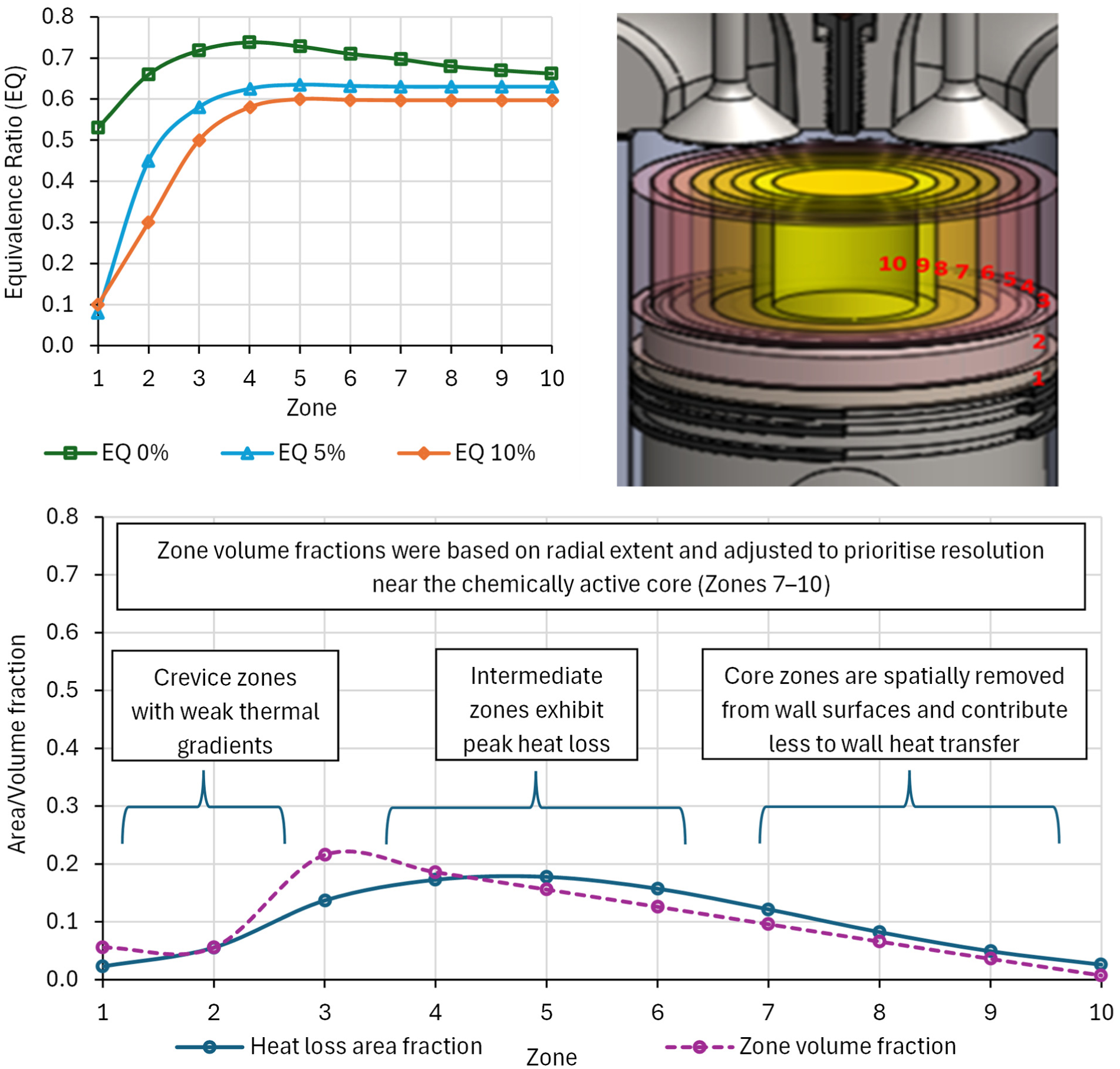
In-cylinder distribution of zone geometry, heat loss and equivalence ratio (0, 5, 10% H2) in the split cycle engine.
The zonal heat loss and volume distributions were derived from established multizone combustion modelling approaches. Prior studies29–31 demonstrate that crevice, boundary, and core regions exhibit distinct thermochemical behaviour, with crevice zones containing relatively stagnant, low-temperature gases, boundary layers experiencing strong wall heat transfer and partial oxidation, and core regions accounting for the majority of the reacting mass and NOx formation. These studies consistently show that only a small fraction of the total mass resides in crevices and near-wall regions, while the bulk of the charge is contained within the core. In the present work, this framework is extended to dual-fuel RSCE operation, where the interaction between port-injected gaseous fuel and direct-injected liquid fuel introduces additional stratification effects.32,33 At constant total fuel energy, increasing the proportion of gaseous H2 promotes mixture homogeneity by reducing locally rich regions associated with direct injection, consistent with CFD observations, and reflected in the progressively more uniform equivalence ratio distributions shown in Figure 3. Accordingly, a radially nested annular zoning structure was adopted, with volume fractions decreasing towards the core to increase resolution in regions of high chemical reactivity.
Heat loss area fractions were assigned based on the zonal mass/stratification distribution, in combination with geometric surface exposure and radial location, and further refined using a Gaussian weighting centred on intermediate zones (Zones 4–5). This weighting mirrors the expected in-cylinder heat transfer distribution, where boundary-layer regions near the wall experience the highest wall losses. It also prevents unrealistic extremes—such as negligible core losses or overestimated crevice contributions—that can arise from purely geometric approaches. Intermediate zones (particularly Zones 3–5) exhibit peak wall heat loss due to high local mixture density, elevated combustion reactivity, and wall contact area. Conversely, core zones (Zones 9–10) are spatially removed from wall surfaces and, despite experiencing strong internal gas convection, contribute less to direct wall heat transfer due to reduced contact. Concurrently, crevice zones (Zones 1–2) contain cooler, relatively stagnant gases with weak thermal gradients.
While not directly calibrated to a specific heat flux dataset, the distribution is constrained by geometric and literature-reported zonal behaviour. The applied profile thus integrates geometric realism with analytically defined thermodynamic behaviour. Importantly, by embedding this spatially resolved heat loss distribution within each zone, the approach compensates for the lack of interzonal heat or mass exchange in the Chemkin-Pro MZ framework, thereby enhancing spatial fidelity within the constraints of the zonal architecture.
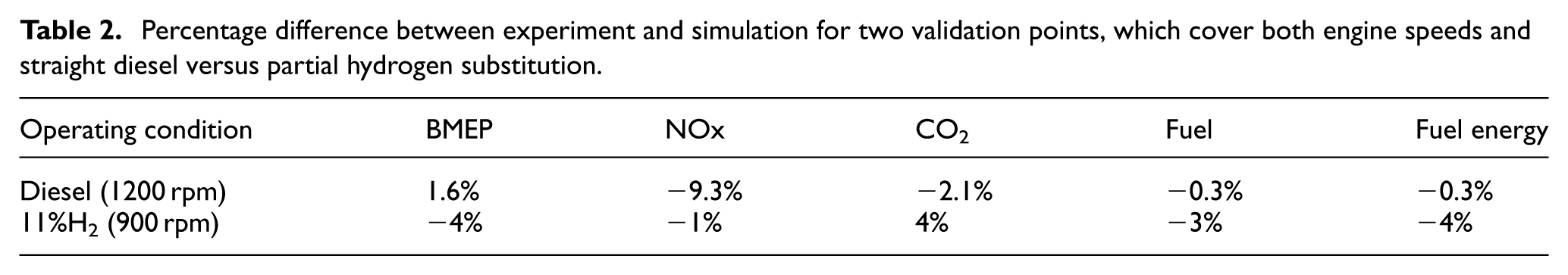
While alternative distributions (e.g. uniform or purely geometry-based) would lead to less physically representative temperature fields—failing to capture cool crevice regions or thermally insulated core behaviour—the overall combustion and emissions trends presented in this study remain governed primarily by the prescribed mixture stratification and global thermodynamic conditions. The Gaussian weighting is therefore intended as a physically informed approximation rather than a calibrated correction. The model does not capture turbulence–chemistry interactions or wall-film effects, and relies on assumptions regarding zone discretisation, heat loss distribution, and radial symmetry; these limitations are consistent with standard MZ frameworks and represent areas for future work. Despite these assumptions, the model reproduces the experimental operating points within acceptable tolerance. Table 2 compares experiment and MZ simulation validation points for two engine speeds and fuelling modes encompassing ML to HL, with neat and diesel-H2 blends: BMEP within 1.6% (diesel—1200 rpm) and 4% (diesel+11%Vol H2—900 rpm); NOx within 9.3% and 1%; CO2 within 2.1% and 4%; and fuel mass and fuel-energy rates within 4%. These errors lie within typical uncertainty bounds for engine simulations and are consistent with the confidence intervals reported for the underlying experimental metrics.
Percentage difference between experiment and simulation for two validation points, which cover both engine speeds and straight diesel versus partial hydrogen substitution.
Hence, the RNM–MZ simulation platform provided a physics-informed tool tailored to hydrogen–diesel dual-fuel RSCE operation. Its spatially resolved configuration offers a physically grounded yet computationally efficient basis for capturing charge stratification, radical formation, and emissions trends within the RSCE expansion chamber.
Results and discussion
Figure 4(a) illustrates the relationship between exergy and internal energy as a function of entropy in the RSCE—derived from an Aspen Plus model that replicated the cycle using theoretically derived quasi-isothermal compression stage and expansion stage data from the SCRE. In this representation, energy and exergy are expressed as system-level flow rates (kW), rather than specific quantities (kJ/kg), to reflect overall energy transfer within the cycle. The thermodynamic states shown in Figure 4 are mapped to the physical processes illustrated in Figure 1. In the RSCE, compression (1→2) occurs in the cold compression cylinder, while combustion and expansion (3→5) occur in the hot expansion cylinder. The intermediate process (2→3) represents charge transfer through the recuperator, rather than an in-cylinder process. As such, the numbered states in Figure 4 do not correspond to a single piston cycle, but to coupled processes occurring across the two cylinders under phase-shifted operation.
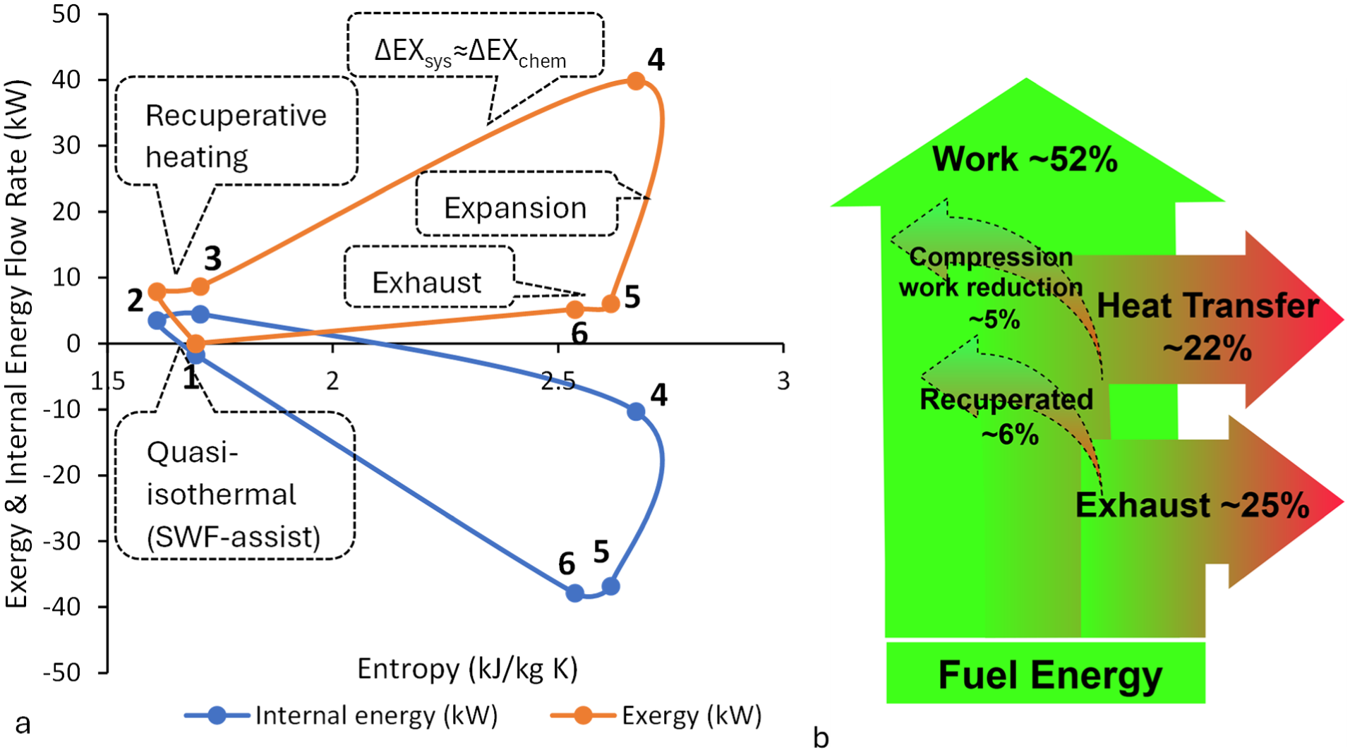
(a) Aspen Plus-derived representation of RSCE energy and exergy flow rates (presented as kW flow rates to reflect system-level energy transfer) versus entropy, (b) Schematic fuel energy distribution showing fuel energy partitioning into major pathways, including useful work (combustion), exhaust losses, heat losses, and potential system-level gains from recuperation and compression work reduction. 34
The RSCE cycle proceeds as follows (reference Figure 4(a)):
1→2: Quasi-isothermal compression of charge air with heat transfer to a SWF. T1 is equal to the ambient, and T2 may be estimated from Refs.22,34 While internal energy and exergy both increase slightly during the quasi-isothermal compression stage, this rise is significantly lower than that observed in compression typical of conventional CI engines. The moderated energy build-up, paired with entropy reduction, reflects a more reversible process that enables improved thermal management and exergy efficiency in the RSCE. The greater the degree of cooling, the greater the temperature difference across the recuperator, along with its associated effectiveness. 22
2→3: The dense, cool charge air passes into the recuperator, recovers heat energy from the exhaust gas—increasing both internal energy and exergy before injection into the expansion cylinder, where the high-pressure-ratio, choked flow conditions (with local transonic behaviour near the valve) 23 promote energetic mixing, supporting homogenous conditions.
3→4: Optimal ignition occurs just after TDC, where chemical energy added during combustion manifests as a sharp exergy gain (ΔEXchem), with the piston beginning its downward motion, enabling approximately constant-pressure heat addition. 22
4→5 Expansion to near BDC enables optimal work extraction and near isobaric exhaust. 22
5→6: Exhaust gas then passes through the internal recuperator and downstream to the aftertreatment.
Compared to a conventional cycle, this structure may enable higher charge preparation flexibility and greater thermal control with associated improved entropy management–critical for high-efficiency, fuel-flexible operation. Figure 4(b) represents a schematic distribution of the total fuel energy input (100%) into key pathways, including useful work, exhaust losses, and heat transfer, alongside indicative system-level contributions from recuperation (∼6%) and quasi-isothermal compression (∼5%). 34 These percentages do not represent additive thermodynamic gains, but rather the relative magnitude of different energy flows within the system.
Section 3.1 details the results obtained from SCRE, and Section 3.2 discusses the outcomes of the simulation.
Split cycle experimental results
Figure 5(a) shows experimental cylinder events for a range of loads and %Vol H2, including an example simulation pressure profile from the validation stages. Figure 5(b) compares hydrogen volumetric fraction in the expander intake (H2 vol% of air) with its corresponding share of total fuel energy (H2+ diesel). Variations in load, air flow, and equivalence ratio alter the relationship between volumetric fraction and energy contribution, leading to the observed spread. The model prescribes initial thermodynamic states, with the resulting trapped mass determining fuel rates. As a result, the simulated points (solid markers) fall within the experimental envelope, indicating that the model produces physically consistent combinations of air and fuel that map correctly between volumetric and energy-based metrics. Importantly, this distribution spans conditions both below and above ∼40% hydrogen energy share, enabling evaluation of the NOx response across this threshold.
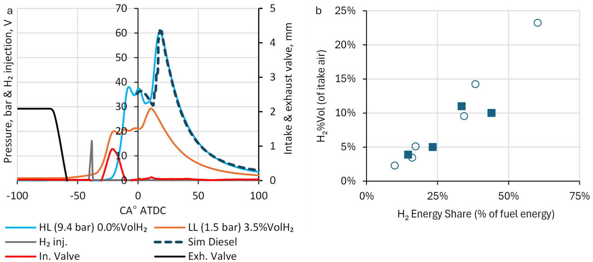
(a) In-cylinder events for a range of loads with simulation pressure trace match, (b) % of fuel energy for the range of %Vol H2 (solid points are simulations).
Pre-ignition heat release from diesel was observed as low as 773 K in the SCRE; however, the knocking was characterised as very light, resulting in only a minor increase in cylinder pressure prior to the main ignition event (Figure 5(a) orange line) and a subsequent drop in torque. This behaviour is attributed to a slow partial reaction of the hydrogen charge, likely initiated via surface ignition on localised hot regions of the combustion chamber. Notably, even in instances where early ignition was detected, the rate of pressure rise during the main combustion event remained controlled and repeatable, contrasting with the erratic behaviour typically associated with classical knock.
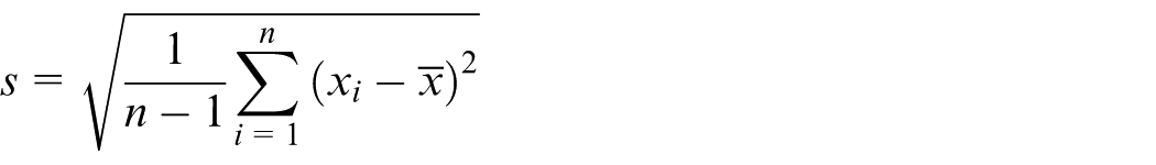
To confirm that these ignition characteristics were not isolated events but repeatable behaviours, cycle-resolved combustion metrics were recorded over 100 consecutive cycles for each condition. For each metric, the sample mean (
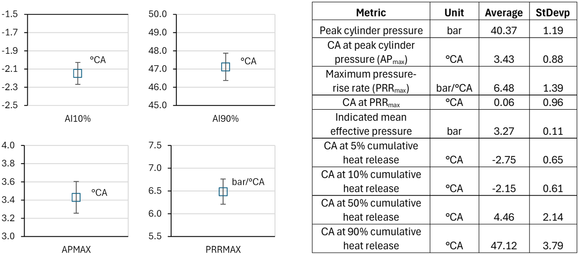
Experiment results for diesel with 10%Vol H2 showing key metrics averaged over 100 cycles with the associated standard deviation and confidence interval, with the Y axis showing °CA.
and the 95% CINT of the mean as:
where t0.975, n−1 is the two-tailed critical value of Student’s t-distribution with n−1 = 99 degrees of freedom. The CoV was used to express variability relative to the mean:
Across all parameters, the SDs were small in absolute terms (SD of IMEP = 0.11 bar, pmax = 1.19 bar, APMAX = 0.88°CA), indicating very limited cycle-to-cycle scatter. CoV was only reported for magnitude-based metrics with strictly positive means (IMEP, pmax), as it is not meaningful for crank-angle metrics near zero. The calculated CoV values were low, with both CoVIMEP and CoVpmax = 3%, demonstrating stable combustion and confirming low variability in dual-fuel operation. The higher dispersion observed for PRRmax (reported as CINT) is consistent with its sensitivity to small fluctuations in mixture and ignition conditions.
To complement the tabulated statistics, Figure 6 also presents the mean values of AI10%, AI90%, APMAX, and PRRMAX with their 95% confidence intervals. The narrow CINT ranges (PRRMAX 6.2–6.8 bar/°CA, IMEP 3.25–3.29 bar) reinforce the low variability observed in the cycle-resolved metrics and provide a visual confirmation of the stability of dual-fuel operation.
Figure 7 shows that the experimental expander campaign tested up to 23%Vol hydrogen substitution across selected conditions. This confirms that the 5% and 10%Vol H2 cases explored in subsequent simulations fall well within the experimentally validated substitution envelope.
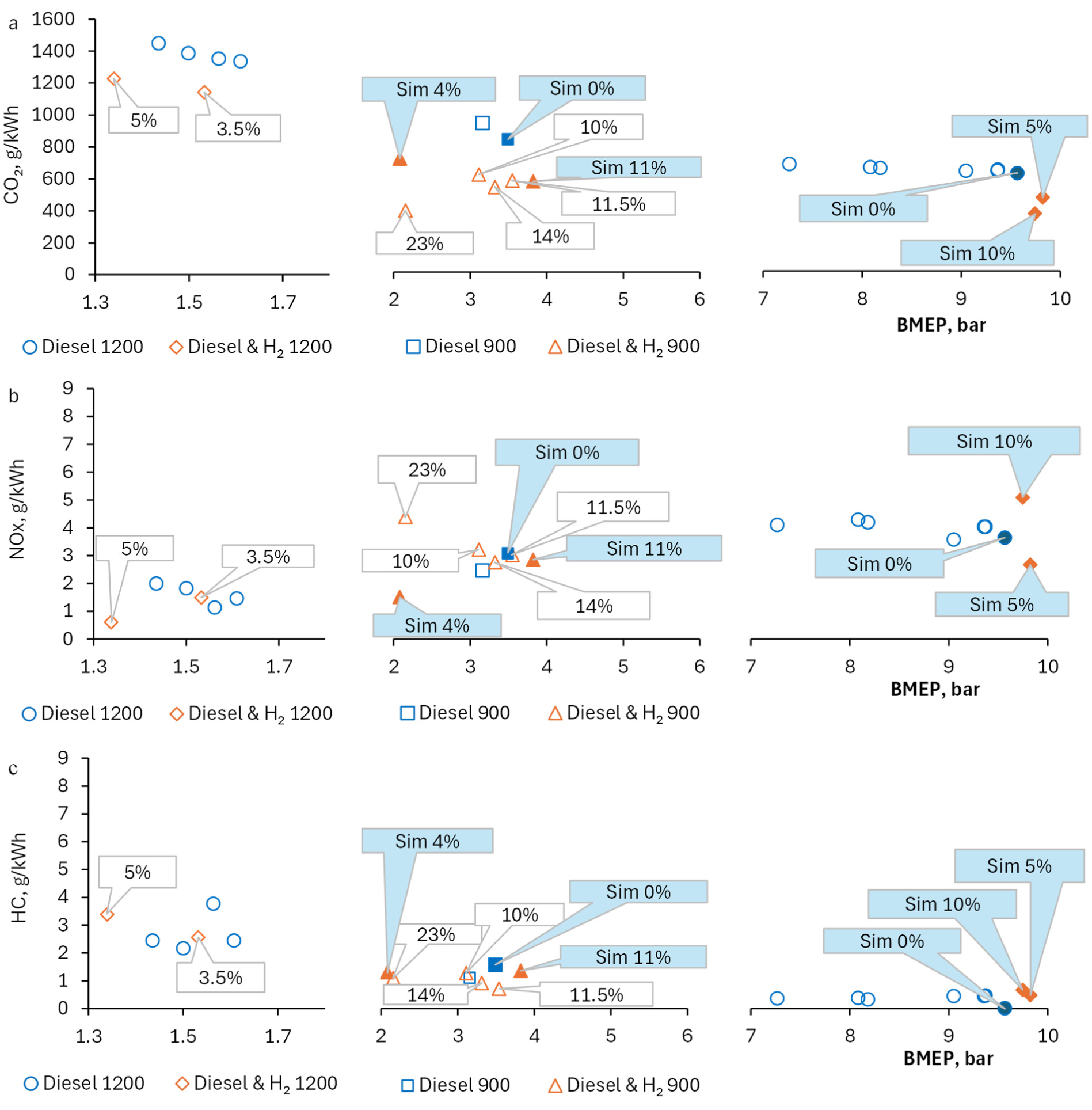
Split cycle expander experiment (hollow markers) and simulation (solid markers) results for diesel and 3.5 to 23%Vol H2 for (a) CO2 g/kWh, (b) NOx g/kWh and (c) HC g/kWh.
This figure shows four key results from the SCRE. Firstly, CO2 per unit expander work decreased with increasing load and %Vol hydrogen (Figure 7(a)). At low/mid load (∼3–4 bar), the 11.5%Vol H2 blend achieved ∼40% CO2 reduction, with negligible increase in NOx (2.9 vs 2.3 g/kWh, Figure 7(b)).
Secondly, assuming a high-efficiency ∼95% SCR, representative of current Euro 6 systems, both high-load diesel and mid-load 23%Vol H2 cases are projected to approach the Euro 7 WHTC NOx target of ∼0.2 g/kWh (Figure 7(b) shows pre-SCR values). This comparison is used as an indicative benchmark, recognising that regulatory limits apply to full drive cycles rather than individual steady-state operating points. Moreover, while detailed SCR modelling, including ammonia slip, was beyond the scope of this study, the considered aftertreatment efficiencies (∼95% for SCR and ∼90% for DPF) are consistent with published data4,6,7 and reflect typical higher-efficiency steady-state performance with well-maintained systems. These values were applied to provide an indicative benchmark of emissions reduction potential, focusing on the expander side impact of hydrogen substitution. It is acknowledged that this simplification does not capture real-world degradation, thermal transients, or slip effects, but it aligns with standard practice in single-cylinder research, where the emphasis remains on combustion and in-cylinder phenomena.
Thirdly, HC emissions for cases with H2 showed similar magnitudes to straight diesel across the engine map, with all expander values below the Euro 7 WHTC benchmark value (0.58 g/kWh for methane and non-methane organic gases, Figure 7(c)).
Finally, to assess the predictive performance of the modelling approach to both matched points and trends in the operating space, simulations were conducted at ML (900 rpm) and HL (1200 rpm) under a range of fuelling and load conditions. Hydrogen substitution levels of 0%–11%Vol were evaluated, with results showing strong agreement with experimental trends in CO2, NOx, and HC emissions (Figures 5(a) and 7(a)–(c)), reinforcing the model’s robustness in extrapolating hydrogen effects. These results confirm that the hybrid RNM–MZ modelling framework accurately captures key thermochemical behaviour and emissions trade-offs under representative RSCE fuelling conditions, supporting its application to untested but practically relevant hydrogen substitution scenarios. The impact of these results is discussed in the following sections.
Combustion and emission simulation results
Hence, the initial expander experimental results suggested that partial hydrogen fuelling in the RSCE configuration could provide the required CO2 reduction with minimal NOx penalty. The selected hydrogen blending ratios (5% and 10%Vol H2) were chosen to explore the effect of low to moderate substitution on detailed combustion and emissions, consistent with practical dual-fuel engine operation. There are three stages to the simulation results. Section 3.2.1 uses the Chemkin RNM to evaluate key species distribution during mixing prior to ignition. Section 3.2.2 shows the addition of 5 and 10%Vol H2 at HL, not explored by the experiment. Finally, section 3.2.3 shows the impact of water on combustion performance, a consequence of using water as the SWF for quasi-isothermal compression.
Reactor network for pre-ignition mixing
The experimental campaign indicated that whilst hydrogen addition improved combustion stability, it also introduced light pre-ignition at higher substitution levels, indicating a shift in ignition characteristics under mixed-fuel conditions. The influence of hydrogen on pre-ignition behaviour arises from both thermal and chemical effects. While its lower specific heat promotes a faster temperature rise, its rapid reaction kinetics and radical-generation potential exert a dominant influence on early ignition behaviour—even at low substitution levels.
To explore the chemical basis for the experimental observations, an RNM was developed to simulate species evolution in the expansion cylinder prior to ignition using a reduced 227-species, 937-reaction chemical mechanism developed by Sun et al. 35 This model reflects the mixing conditions unique to the RSCE architecture—formed after compression, recuperation and during mixing—and enables assessment of radical chemistry before combustion onset.
Figure 8 compares pre-ignition molar fractions of key species for diesel-only and 10%Vol H2 substitution. Figure 8(a) shows that hydrogen addition increased the formation of HO2, H2O2, and OH radicals, all associated with high-pressure low-temperature reactivity. These species appear prior to ignition, indicating that early-stage chemistry is activated during the induction-mixing phase. By contrast, Figure 8(b) shows that unsaturated hydrocarbons (e.g. C2H4, C3H6, C4H8) and the PAH proxy (a2CH2) remain at similar concentrations across fuel cases within the model resolution. Taken together, this pattern suggests a shift towards earlier chain-propagating conditions (radical pool increase) without engaging bulk cracking or PAH growth during the mixing window—consistent with the light, repeatable pre-ignition observed experimentally rather than a chamber-wide chain-branching runaway.
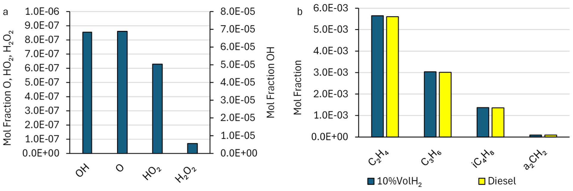
Pre-ignition RNM species at T≈700K for diesel and 10%Vol H2 (a) Radical pool (HO2, H2O2, OH). (b) Unsaturated hydrocarbons/PAH proxy (C2H4, C3H6, C4H8, a2CH2). Hydrogen enrichment increases radicals while leaving major olefins and a2CH2 effectively unchanged in this window, indicating radical-driven early heat release without bulk cracking/PAH growth. Species are simulated (RNM); in-cylinder stratification is not directly measured.
The following reaction chain (R1–R5) illustrates how hydrogen enhanced the radical pool, particularly via pressure-dependent HO2 formation. The forward rate of reaction R1 increases with pressure, initiating the chain R1 → R2/R3 → R4 → R5:


The early formation of HO2 and OH suggests a shift in pre-ignition reactivity under hydrogen substitution, consistent with the observed trends in combustion phasing and hot-spot sensitivity.
While the experiment showed negligible change in HC emissions between diesel and H2 blends (Figure 7(c)), it is important to note that in both Chemkin-Pro and experimental gas analysis, HC emissions represent unburnt or partially oxidised gas-phase hydrocarbons, not solid-phase soot. Therefore, shifts in radical chemistry that alter soot formation pathways (e.g. OH attack on C2–C3 precursors) may not be reflected in HC emissions, even if particulate mass is reduced.
With respect to soot pathways, a2CH2 remains approximately unchanged; accordingly, the work does not infer a change in soot propensity from the pre-ignition window alone. Nevertheless, the elevated OH concentration (Figure 8(a)) could suppress HACA-type (Hydrogen-Abstraction-C2H2-Addition) PAH surface growth where acetylene is present, via the canonical reaction:

This pathway reduces the availability of C2H2 for aromatic ring growth, thereby limiting soot formation despite unchanged levels of upstream hydrocarbons. Similar suppression has been reported in hydrogen-enriched diffusion flame studies, 36 where increased OH inhibits soot surface growth even when PAH nucleation rates remain stable.
The elevated pre-ignition OH provides a mechanistic rationale for reduced particulate propensity under hydrogen enrichment—via disruption of soot chemistry and radical competition—even when bulk HC remains unchanged; however, confirmation would require explicit C2H2 tracking in the RNM or direct particulate measurements beyond the present scope. This mechanism is consistent with the experimental behaviours in Section 2.1: enhanced combustion stability, greater ignition-retard potential, and the onset of low-level pre-ignition at higher hydrogen ratios.
Substitution of diesel with hydrogen
Hydrogen exhibits high reactivity under RSCE conditions due to its low ignition energy and wide flammability limits, which, when combined with the elevated intake temperatures and pressures of the expansion cylinder, increase the system’s sensitivity to pre-ignition compared to conventional diesel-only operation (Figure 5). Accordingly, the hydrogen substitution levels used in this study are directly informed by these reactivity constraints, with higher fractions explored experimentally to identify practical limits and lower fractions (5–10%Vol H2) selected for detailed simulation, balancing reactivity benefits against combustion stability and safety considerations.
To evaluate the model’s predictive performance under representative RSCE conditions, simulation results at ML (900 rpm) and HL (1200 rpm) with up to 11%Vol H2 substitution were compared against experimental data (Figure 7). The model was calibrated using diesel-only SCRE results and validated across key metrics—BMEP, BSFC, CO2, NOx, and HC—with close agreement across test points (within ±10%, Table 2). The simulated pressure trace (Figure 5(a)) confirms accurate reproduction of key combustion characteristics, including ignition delay, pressure rise rate, combustion duration, and heat release timing. This indicates the RNM–MZ framework effectively captures in-cylinder thermochemical evolution under diesel baseline conditions, providing confidence in its extension to dual-fuel operation. Predicted emissions across the load range also follow experimental trends, reinforcing the model’s robustness across different fuelling conditions. Figure 7 shows that the simulations reproduce the main observed emissions responses: a decrease in CO2 with increasing hydrogen substitution, a non-monotonic NOx response with hydrogen addition, and HC levels that remain within the experimental order of magnitude across the tested range. To provide a quantitative check on trend agreement, the CO2 response to hydrogen substitution was normalised to the corresponding diesel baseline within comparable operating groups. Experimentally, CO2 decreased by approximately 16% at low load (3.5–5%Vol H2) and 39% at mid load (11.5%Vol H2). The corresponding simulations predicted reductions of approximately 15% at 4%Vol H2 and 32% at 11%Vol H2, indicating that the model reproduced both the direction and approximate magnitude of the measured CO2 response to hydrogen addition. Collectively, these results demonstrate that the RNM–MZ platform reliably captures both combustion dynamics and emissions trade-offs, supporting its application to untested but practically relevant dual-fuel strategies in this context.
Figure 9 compares the SCRE diesel HL point (Exp-D, 9.4 bar) with (i) the validated MZ model at the same point (Sim-D; ±5% agreement guide shown) and (ii) simulated substitution of diesel with 5% and 10%Vol H2. Figure 9(a) indicates that BMEP is predicted to be maintained with H2 substitution, while BSFC is reduced by 23% (5%Vol H2) and 33% (10%Vol H2), reflecting the lower fuel mass flow required to hold constant fuel energy (−17% and −27% total fuel mass flow, respectively).
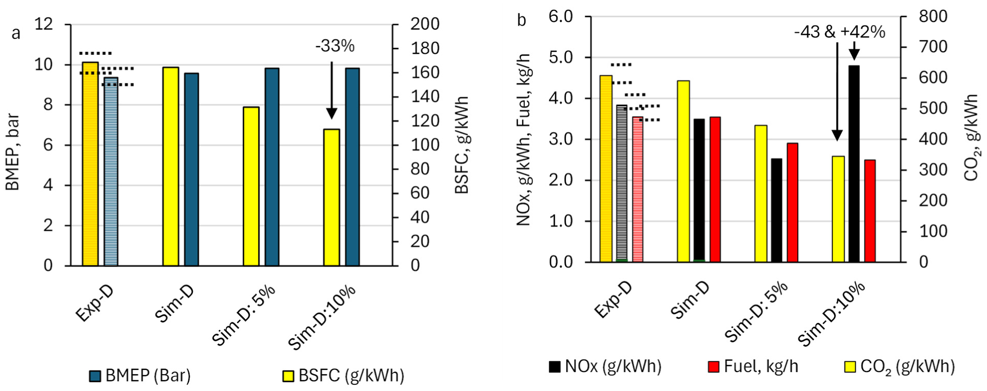
Comparison of the HL diesel SCRE data (hatched bars) with the model (solid bars) reproducing the results, followed by diesel substitution with 5% and 10%Vol H2, showing impact on (a) BMEP, BSFC and (b) NOx, CO2 g/kWh. Dashed guides indicate a ±5% agreement criterion relative to the experimental mean and are not measurement uncertainty.
Figure 9(b) indicates a near linear CO2 decrease with increase in H2, predicting up to 43% reduction at 10%Vol H2. Conversely, the NOx response is predicted to be non-monotonic: at 5%Vol H2, NOx decreases by 23%, but at 10%Vol H2 it increases by 42%. This behaviour is consistent with competing effects. At modest substitution, the drop in total fuel mass and a higher H2O/CO2 product ratio raise mixture heat capacity and reduce peak temperature (≈100 K), suppressing thermal NO. As the H2 energy share approaches ∼40–45%, two effects dominate: (1) faster chemistry and a larger premixed fraction advance and intensify heat release, increasing peak temperature and high-temperature residence time; and (2) the enlarged O/OH radical pool accelerates the extended Zeldovich path (N2+O⇌NO+N; N+OH→NO+H), driving NO formation despite reduced carbon. This threshold-like rise is consistent with the +42% NOx observed experimentally at 23%Vol H2 (Figure 7(b)) and the findings from section 3.2.1. Nonetheless, with a 95% SCR assumption, the 5%Vol H2 case is predicted to meet the expander 0.2 g/kWh WHTC benchmark, while 10%Vol H2 is predicted to slightly exceed it (but remains within the 0.26 g/kWh on-road limit).
Because the high-load hydrogen cases are simulation-only, they inherit the uncertainty of the calibrated MZ framework and should be interpreted as indicative of trend direction and relative magnitude, rather than exact point predictions. However, the model’s ability to reproduce matched experimental points within ±10%, together with the fact that the simulated H2 fractions lie within the experimentally explored substitution envelope, supports the use of these cases for assessing trend behaviour and practical sensitivity at high load. This is consistent with general sensitivity behaviour observed in engine modelling studies, where the dominant drivers of emissions trends are global thermodynamic conditions and mixture reactivity, and moderate variations in parameters such as heat transfer or initial conditions primarily affect absolute magnitudes rather than overall trends. Future research should extend mechanism fidelity checks at these RSCE conditions and explore mitigations (e.g. later CA50, increased SWF/H2O fraction, cooled EGR, or pilot strategy changes) to curb high-share NOx.
Impact of water content in charge mixture
The RSCE enables quasi-isothermal compression by exchanging compression heat with a SWF—here, water—so a non-negligible H2O fraction can enter the expansion cylinder with the charge. The H2O fractions considered (0.01–0.10%Vol) were selected to represent small but non-negligible levels of SWF carry-over into the expansion cylinder, enabling a controlled parametric assessment of its impact on combustion and emissions. The upper bound was chosen to capture the onset of HC sensitivity to charge dilution and temperature reduction, thereby defining a practical operating window rather than representing a calibrated or optimised condition. The aim here is to quantify, for an H2-diesel RSCE at high load, how SWF-derived water in the expander intake mixture affects temperature history and regulated emissions. This RSCE-H2–specific assessment of SWF carry-over effects has not been reported in the literature.
The H2O effect is isolated using the validated RNM-MZ framework (Sections 2.2–3.2.2), holding geometry and fuel-energy input constant and varying only the charge H2O fraction for the HL operating point with 5%Vol H2. Direct measurement of in-cylinder stratification and thermodynamic gradients is not feasible on the current SCRE; hence, simulation is used here as a controlled numerical experiment to separate SWF impacts from hardware/calibration changes.
Figure 10 explores adding a small H2O fraction to the expander intake (up to 0.10% by vol.) to emulate SWF carry-over. All preceding cases produced expander-out HC within the Euro 7 benchmark (<0.58 g/kWh). At 0.10% H2O, NOx falls by ≈30% (Figure 10(b)), with a marginal BMEP penalty (≈3%, Figure 10(a)). However, the same dilution that suppresses thermal NO—higher mixture heat capacity, lower peak temperature and shorter high temperature residence—also slows post-flame oxidation (reaction kinetics decreases with temperature) and reduces OH availability, increasing the quench distance in boundary layers/crevices. Consequently, more partially oxidised fuel fragments survive to EVO, and HC rises at 0.10% H2O. Concurrently, the MZ model does not include post-EVO oxidation in the exhaust port/manifold, so it does not capture the marginal ∼2% HC reduction from oxidation in hot residuals. 37 Moreover, RSCE expansion-cylinder insulation should reduce wall-quench HC by ∼5% of engine-out HC, implying the simulated HC penalty at 0.10% is likely conservative.
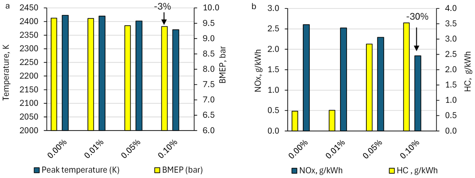
Comparison of 5%Vol H2 with 0–0.1% water in reactants showing impact on (a) peak temperature, BMEP and (b) NOx, HC g/kWh.
Taken together, modest SWF carry-over appears to retain most of the NOx benefit with limited HC impact, whereas higher fractions trade NOx for HC due to temperature-limited oxidation. To retain the NOx benefit while avoiding an HC penalty, mitigation strategies may include: (i) limit SWF carry-over; (ii) co-tune phasing/air-path—apply a small CA50 delay (≈1–2°CA) and a modest λ increase (Δλ ≈ 0.05–0.10) to preserve late-cycle/exhaust temperature and supply excess O2 for post-flame oxidation; and (iii) use a standard aftertreatment stack—DOC → DPF (or CDPF) → SCR → ASC. The DOC (upstream of the DPF) is fully compatible and reduces residual HC/CO while generating NO2 for passive DPF regeneration; SCR (assumed ∼95% conversion) treats engine-out NOx; the ASC controls NH3 slip. These measures preserve most of the SWF-enabled NOx reduction while containing HC, with calibration bounds set by stability, efficiency, and component temperature limits.
To extend the analysis from the expander to a whole split cycle system prediction, the temperature at the end of quasi-isothermal compression (C = 0.7) was calculated from:
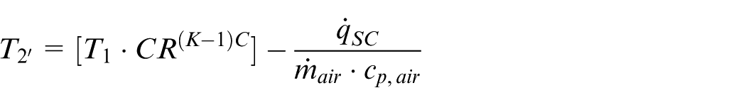
This enables the determination of the enthalpy change and feasible range of work transfer during quasi-isothermal compression (5 –10 kW/cylinder). Including this reduced negative work in the 0.1% data set, and applying an assumed 90% DPF efficiency, predicts exhaust-out HC emissions of 0.46–0.67 g/kWh, that is, within the Euro 7 benchmark. This suggests that the proposed system configuration could remain emissions-compliant at the system level, subject to the assumptions outlined.
From a broader system perspective, H2O carry-over may introduce additional effects beyond those captured in the present combustion-focused analysis. The increased heat capacity of the working fluid may enhance heat uptake in the recuperator and improve thermal matching with the exhaust stream, while also moderating temperature decay during expansion and exhaust, with potential implications for aftertreatment performance. It should also be noted that the H2O fractions considered here represent controlled, idealised conditions within the simulation framework. In a practical RSCE system, SWF carry-over would depend on injection strategy, phase behaviour, and separation efficiency, and may not be directly controllable. Higher water fractions may also introduce engineering considerations such as interaction with lubrication films, corrosion risk, and integration with the broader thermal management and recuperation system. As such, the present results are indicative of thermodynamic potential, with practical implementation requiring further system-level development.
Future research direction
The presented work has experimentally demonstrated hydrogen-diesel fuelling in a split-cycle engine. The integrated experiment–simulation framework, comprising the RNM→MZ approach with physically informed zonal stratification (volume, mass, and heat-loss distribution), was validated against experimental data and used to guide H2 and SWF strategies for efficiency–emissions trade-offs. The following is a synthesis of the proposed research directions to enhance the technology level of a low-carbon split-cycle engine.
In the form of near-term calibration & hardware on the current SCRE.
Higher-pressure H2 injector to enable induction-phase injection at RSCE expander intake pressures. This mitigates surface-induced pre-ignition and expands H2 substitution. Target: restore typical RSCE intake pressure while maintaining stable phasing and PRR limits.
Pilot shaping (if pilot retained) to sustain late heat release and reduce quench-generated HC.
Combustion system evolution.
Spark-ignition pathway evaluation for long-term viability (pre-chamber/torch or SI-assist). Risks: NOx and knock at high H2 shares; Mitigations: dilution, SWF carry-over control, CA50 scheduling.
Hydrogen share & NOx inflection mapping.
Systematically map the NOx rise threshold as H2 energy share approaches/exceeds ∼40–45%, separating effects of faster heat release/high-temperature residence from carbon-dilution benefits. Target: a calibration window delivering ≤0.2 g/kWh NOx (post-SCR) at high load or define the additional controls.
Model & mechanism development.
Extend the RNM→MZ framework with (i) post-EVO oxidation coupling, (ii) tracking of key soot/PAH precursors to substantiate particulate propensity statements.
Time-resolved transient NOx modelling has been proposed to improve prediction accuracy in hydrogen–diesel engines under dynamic conditions38; extending the present steady-state framework to transient operation represents a logical next step towards calibration and control deployment.
Safety, infrastructure, and durability.
H2 leak detection, injector durability at raised Δp, and implications for refuelling/infrastructure; thermal limits for insulated hot-cylinder components under high-load dual-fuel operation, including control of pre-ignition under elevated temperature and pressure conditions.
Conclusion
To guide efficiency-led decarbonisation concepts to meet tighter future emission limits in heavy-duty applications, the novelty of the current work is in its assessment of hydrogen-diesel dual fuelling in a recuperated split-cycle engine (RSCE, Figure 2). Experiments were performed using a single cylinder research engine (SCRE) at 900/1200 rpm (1.3→9.4 bar BMEP; up to 23%Vol H2 for ∼46% duty-cycle coverage, Figure 7). Results were extended using the Chemkin-Pro Reactor Network Model (RNM)→ Multizone engine model (MZ) framework, to evaluate high load H2 substitution (up to 11%Vol), pre-ignition chemistry and secondary working fluid (SWF—water) carry-over from quasi-isothermal compression. The experimental results demonstrate stable dual-fuel operation, while the validated modelling framework provides insight into higher-load behaviour and associated emissions trade-offs. In particular, hydrogen enrichment offers significant reductions in BSFC and CO2, but introduces a non-monotonic NOx response linked to changes in combustion phasing and radical chemistry. The key findings are summarised as:
Experiment feasibility and stability: Consistent, repeatable dual-fuel operation across tested points, with light, repeatable pre-ignition at higher H2 controllable via conservative timing (Figure 5).
Performance and CO2: At higher load (HL, simulated extensions), the model predicts BMEP to be maintained, with BSFC reductions of 23% (5%Vol H2) and 33% (10%Vol H2), resulting in predicted CO2 reductions of 28% and 43% (Figure 9(a)).
NOx trade-off: The model predicts a non-monotonic NOx response, with a 23% reduction at 5%Vol H2 and a 42% increase at 10%Vol H2 as H2 energy share approaches ∼40%, attributed to faster chemistry, greater premixed burn, and increased peak-temperature residence (Figure 9(b)). With an assumed ∼95% SCR efficiency, the 5%Vol case is predicted to meet the 0.2 g/kWh WHTC benchmark, while the 10%Vol case slightly exceeds this but remains within the ≈0.26 g/kWh on-road limit.
Mechanism (pre-ignition window): RNM results indicate increasing HO2/H2O2/OH with H2, while olefins/PAH proxy species remain largely unchanged, suggesting localised early heat release (rather than runaway behaviour) (Figure 8(a)), consistent with the measured pressure behaviour.
SWF carry-over (water): The model predicts that adding 0.10% H2O reduces NOx by ∼30% with a ∼3% BMEP penalty, while HC is predicted to increase due to temperature-limited oxidation (Figure 10). Modest levels of SWF are therefore expected to retain most of the NOx benefit with limited HC impact.
Furthermore, key split-cycle experimental and modelling contributions include:
Experimental demonstration of port-injected H2 in an RSCE (retrofit dual-fuel SCRE) with a validation dataset (100-cycle stats) at representative points (Figure 6).
Validated RNM→MZ framework for RSCE H2, incorporating physically informed zonal stratification (volume fraction, mass distribution, and heat-loss treatment) to represent radial thermochemical behaviour within the constraints of the non-interacting zonal framework (Figure 3).
Mechanistic insight linking radical-pool growth (HO2/H2O2/OH) to observed light pre-ignition and the NOx inflection as H2 energy share exceeds 40%.
Quantified SWF (water) carry-over effects on NOx/HC/BMEP at HL—rarely reported for RSCE-H2.
In summary, this work provides a critical validation step, linking experimental RSCE data to pre-ignition behaviour and modelled combustion stability under expander port-hydrogen and direct injection diesel dual-fuelling conditions. The combined experimental results and validated RNM→MZ framework indicate that hydrogen enrichment can support stable RSCE operation at representative points, and that elevated pre-ignition radical formation explains the observed light, repeatable early heat release. These findings help to define practical operating constraints and inform pathways towards emissions-compliant deployment. Taken together, the results suggest that RSCE with partial H2 (combined with quasi-isothermal compression and recuperation) represents a credible mid-term route to decarbonisation, while preserving heavy-duty performance and supporting progress towards EU CO2 targets.
Footnotes
Appendix
Ethical considerations
This article does not contain any studies with human or animal participants.
Author contributions
Angad Panesar: Conceptualisation; Data curation; Funding acquisition; Investigation; Methodology; Project administration; Resources; Supervision; Validation; Visualisation; Writing—review & editing. Elisa Wylie: Conceptualisation; Data curation; Formal analysis; Investigation; Methodology; Software; Validation; Visualisation; Writing—original draft.
Funding
The authors disclosed receipt of the following financial support for the research, authorship, and/or publication of this article: Contributions to the presented work, firstly by Nick Owen and Robert Morgan on the APC UK Ltd. (ARMD20 1010), and secondly support via RAEng TSP (2526-7110 and 2325-5-IN\145), EPSRC (EP/W016656/1 and EP/Y024605/1) is acknowledged.
Declaration of conflicting interests
The authors declared no potential conflicts of interest with respect to the research, authorship, and/or publication of this article.
Data availability statement
The data that support the findings of this study are available from the corresponding author, Angad Panesar, upon reasonable request.*