






Abstract
Cavitation commonly occurs in fuel injector nozzles, yet the mechanism by which needle valve eccentricity affects in-nozzle string cavitation remains unclear. This study focuses on the development of string-cavitating flow fields and vortex structures influenced by needle valve eccentricity within the nozzle orifice. The Reynolds Stress Model, along with the Volume of Fluid method and the modified Zwart–Gerber–Belamri cavitation model, was employed to evaluate the effects of varying needle valve eccentric distances and orientations on internal flow dynamics. Increasing needle valve eccentricity results in a significantly asymmetric cavitation distribution within the nozzle, enhances vorticity in the main flow region, and strengthens cavitation-vortex interactions, thereby suppressing pressure oscillations. Needle valve eccentricity also significantly alters the intensity and frequency of phase transitions (i.e. fuel vaporization and condensation) within the nozzle orifice. Additionally, needle valve eccentricity promotes vortex instability and increases vortex breakup frequency, while reducing the nozzle flow coefficient by approximately 1–17% compared with the centrally symmetric reference geometry. Needle valve eccentricity fundamentally alters the internal cavitating flow, which can be detrimental to spray uniformity and which is likely to influence subsequent atomization and combustion processes. These findings lay a foundation for optimizing nozzle design to alleviate cavitation-induced flow instability and enhance spray performance.
Introduction
In modern compression-ignition engines, the digitally controlled multiple injection strategy, which splits the main injection into multiple closely spaced smaller injections, is widely applied to alleviate combustion exhaust emissions without compromising fuel efficiency and engine performance. These advanced strategies place increasingly stringent demands on the stability and repeatability of fuel injection processes, making the internal flow characteristics of injector nozzles a crucial factor influencing overall combustion behavior. High-pressure fuel injection is a core technology in such systems, as internal nozzle flow critically governs fuel delivery, spray atomization, and subsequent combustion. 1 Cavitation, formed within injector nozzles during injector needle opening and closing, plays a dual role in that it can promote primary breakup and atomization but also induces flow instability, pressure pulsations, and material erosion that impair injector reliability and durability.2–5 Among various cavitation phenomena, vortex-induced string cavitation, which originates from low-pressure vortex cores, has received growing attention due to its significant impact on atomization and jet stability,6–8 and is now recognized as a key phenomenon in studies on internal nozzle flow. Recent experimental and numerical studies3,8–10 have shown that nozzle micro-deformations and needle valve motion significantly alter cavitation morphology and its impact on spray characteristics. These findings underscore the importance of understanding how geometric topologies and needle dynamics affect internal flow and cavitation behavior.
Current research on nozzle cavitation has advanced our understanding of the influence of nozzle geometry,11–13 fuel properties,14,15 dynamic factors,16,17 and wall roughness,15,18 and various numerical approaches have been developed to capture the complex two-phase flow and phase transition processes.19–22 For example, He et al. 23 and Koukouvinis et al. 24 respectively evaluated the performance of different turbulence models coupled with different cavitation models in predicting vortex cavitation and geometrically induced sheet cavitation within nozzles. Using experimental visualization techniques and numerical simulation, He et al. 17 and Sun et al. 11 investigated how geometric parameters of the nozzle (such as inlet fillet radius and orifice taper coefficient) and dynamic factors (such as injection pressure, needle lift, and needle eccentricity) affect cavitation evolution and flow characteristics in high-pressure fuel injectors. Hu et al. 25 and Sou et al. 26 employed the LES-VOF (Large Eddy Simulation-Volume of Fluid) method and experimental approaches, respectively, to examine the cavitation distribution in the near-orifice region of full-scale diesel injector nozzles and simplified two-dimensional nozzles, and its subsequent influence on near-field spray characteristics. However, only a few studies27–29 have addressed the effect of needle valve motion or eccentricity on internal flow and spray uniformity, and systematic parametric investigations remain limited to the best of the authors’ knowledge. In modern engines, the adoption of a complex multiple injection strategy relies on the ability of the injector to accurately meter extremely small quantities of fuel per event throughout the engine lifetime. Such stringent precision requirements make the mechanical and hydraulic stability of the needle motion a critical factor for ensuring injection repeatability and combustion consistency. In practice, however, needle valve eccentricity, which refers to the lateral displacement or elastic deflection of the needle valve stem within the valve body guide hole, deviating from the ideal centerline trajectory, is almost unavoidable under high-pressure operating conditions. This eccentricity can introduce asymmetric flow and cavitation development, thereby compromising the stability and effectiveness of multi-injection strategies.
In real-world high-pressure fuel injectors, needle valve eccentricity is common and intensifies with increasing injection pressure,30,31 influenced by manufacturing tolerances, assembly clearances, elastic deformation, and transient fluid–structure interactions. It exerts significant and complex regulatory effects on orifice-inlet flow configurations, local contraction, and vortex formation pathways. Previous studies have shown27,32,33 that needle valve eccentricity can cause uneven injection and flow fluctuations. For example, Jin et al. 27 explored the effects of needle eccentricity on the flow, injection and spray characteristics of a double-layered eight-hole nozzle and revealed flow asymmetry and stronger impacts on the lower-layer holes. Huang et al. 32 employed X-ray imaging on diesel injectors with 3, 5, and 8 holes and unveiled that the frequency of needle eccentricity depends on the injector mechanical properties, its amplitude is influenced by the in-nozzle flow, and spray velocity oscillations originate from the sac chamber. However, the effects of eccentric distance and orientation on vortex core strength, string cavitation distribution, phase change dynamics, and the overall flow coefficient remain insufficiently explored. Moreover, recent research indicates34–36 that even minor variations in needle or hole geometry and modeling assumptions can lead to significant changes in predicted cavitation behavior. This highlights the necessity for a systematic assessment of needle valve eccentricity, particularly regarding the formation and stability of vortex-induced string cavitation. However, the effect of needle valve eccentricity on the nozzle flow characteristics and on the spatial distribution of vortex-induced string cavitation has not been examined in detail. For instance, there is a lack of parametric studies on eccentric angles (e.g. 0°, 45°, 90°), making it difficult to quantify the influence of eccentric direction on string cavitation distribution. Furthermore, the interactions among eccentricity, vortex dynamics, and string cavitation have not been systematically coupled, and parametric simulations exploring the relationship between eccentric angle and distance remain unavailable.
To address the aforementioned research gaps, this study aims to systematically investigate the regulatory role of needle valve eccentricity on string cavitation, vortex structure, and flow characteristics within the nozzle through controlled numerical parameterization research. The specific objectives include: (1) quantitatively assess the effects of eccentric distance and angle on vapor phase distribution and its fluctuations within the nozzle; (2) analyze how eccentricity alters the generation, merger, and dissipation processes of primary and secondary vortices, and to utilize objective vortex identification methods (such as the Ω method 37 ) to characterize its influence on vortex topological structures; (3) investigate spatial variations in local evaporation and condensation rates under eccentric conditions, evaluate the effect of eccentricity on the nozzle flow coefficient and its transient fluctuations, and establish a causal framework that links geometric eccentricity, vortex dynamics, cavitation behavior, and overall flow performance. Based on literature reviews and preliminary observations, the following hypothesis is proposed: needle valve eccentricity leads to a narrower contraction channel on the eccentric side. According to Bernoulli’s equation, this constriction increases the local flow velocity, which enhances vortex generation and favors the formation of strong vortex nuclei,38–40 thereby inducing or amplifying string cavitation on that side. This structural asymmetry is expected to cause an uneven cavitation distribution, increase cavitation fragmentation frequency and instability, and reduce the nozzle mass flow coefficient under most operating conditions compared with the concentric reference case. This hypothesis is supported by recent experimental and analytical results, 41 which indicate that minor geometric asymmetries and needle movement can significantly alter vortex formation and cavitation lifecycle within the nozzle. As will be demonstrated in this study, the numerical results confirm this hypothesis: needle valve eccentricity induces pronounced asymmetric cavitation distributions, enhances vorticity and cavitation-vortex coupling, reduces the nozzle flow coefficient by up to 17% (for A45E16), and significantly alters the evaporation–condensation dynamics within the nozzle. Notably, mild 90° eccentricity (A90E8) effectively suppresses cavitation fluctuations while maintaining reasonable flow efficiency.
To achieve these objectives, this study employs a validated Computational Fluid Dynamics (CFD) framework combining the Volume of Fluid (VOF) method, the modified Zwart–Gerber–Belamri (ZGB) cavitation model, and the Reynolds Stress Model (RSM), enabling detailed resolution of cavitation–vortex interactions.23,36 A two-hole mini-SAC nozzle is selected as the reference geometry because it is representative of light-duty diesel injector geometries 12 and allows clear observation of left–right cavitation asymmetry while avoiding the complex multi-hole flow interactions in 8-hole nozzles. 27 It should be noted that in a typical 8-hole nozzle, inter-hole flow interactions, circumferential pressure gradients, and more complex vortex structures may modify the eccentricity effects observed here. Nevertheless, the fundamental mechanisms identified in this study—namely, the channel narrowing, vortex enhancement, and asymmetric cavitation induced by needle eccentricity—are expected to remain qualitatively applicable to multi-hole nozzles, as confirmed by Jin et al. 27 who observed similar eccentricity-induced flow asymmetry in an 8-hole nozzle. Future work extending this parametric framework to multi-hole geometries is recommended to quantify any differences arising from inter-hole coupling. Seven needle valve eccentric configurations are systematically examined under a fixed needle lift to explore the effects of eccentric distance and orientation. Through this parametric investigation, the work elucidates the effects of needle valve eccentricity on cavitation morphology, vortex dynamics, phase transition behavior, and nozzle flow performance. The findings are expected to advance the fundamental understanding of string cavitation mechanisms and providing engineering guidance for injector design and reliability.
The remainder of this paper is organized as follows: Section 2 describes the numerical methods, geometric parameters, boundary conditions, and mesh independence tests; Section 3 presents model validation and discusses the results of the eccentricity parameterization study, including cavitation distribution, vortex core identification, phase transition analysis, and flow coefficient evaluation; Section 4 concludes with a summary of the main findings.
Methodology
Numerical simulation methods
In the present work, the commercial CFD code ANSYS Fluent 42 was adopted to simulate the two-phase with three-component nozzle flow using the VOF model, where all phases share a single momentum field, and local volume fractions are advected and constrained to sum to unity. The VOF model was employed to resolve cavitating gas–liquid flow in the nozzle comprising three components (liquid diesel, diesel vapor, and entrained air), so that interfacial dynamics are tracked via the volume-fraction conservation equations. Considering that the focus of the study is to resolve the string cavitation at normal fuel operating temperature within the injector, where the variation of temperature does not exceed 10 K for the pressure drops considered, the isothermal assumption has been adopted in the present study. Therefore, the energy conservation equation is not solved in the present work. The equations for continuity, momentum, and the mass conservation equations for the vapor and the air are as follows:




where


where
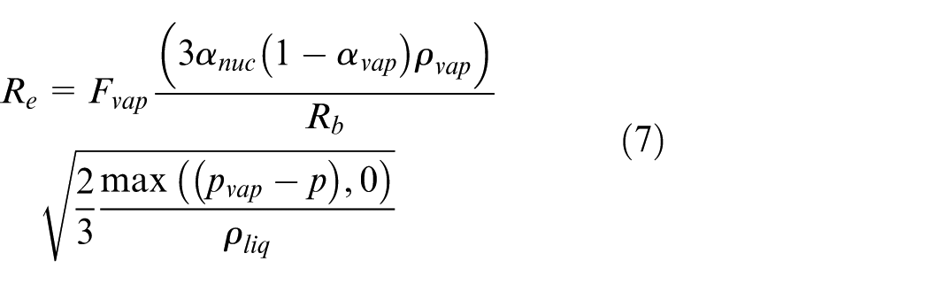

where the bubble radius of 0.001 mm, the nucleation site volume fraction of 5 × 10⁻⁴ evaporation coefficient of 50 and condensation coefficient of 0.01 follow the original recommendations of Zwart et al. 43 and the default ANSYS Fluent settings, which have been widely validated for diesel injector nozzle flows.44,45
Models derived from the Rayleigh-Plesset equation are commonly used to simulate cavitating flow fields. A major challenge associated with these models lies in the strong dependence of numerical accuracy and stability on empirical coefficients. Specifically, in the ZGB cavitation model, an increase in the evaporation coefficient or a decrease in the condensation coefficient, the latter having a more pronounced effect, enhances the accuracy of cavitation predictions across various geometries and flow conditions.44,45 Furthermore, a decrease in


where the coefficient
Reynolds-averaged Navier-Stokes (RANS) methods are widely used to simulate geometry-induced cavitation in injector nozzles,9,49,50 while numerical simulations of string cavitation, whose onset mechanism differs fundamentally, remain limited. Capturing string cavitation demands models that can represent coherent vortical structures and account for turbulence anisotropy, rather than relying on isotropy assumptions. RSM51,52 overcomes the limitations of eddy-viscosity closures by solving transport equations for the Reynolds-stress tensor
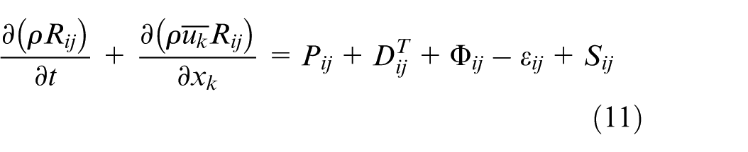
where
Nozzle geometry and boundary conditions
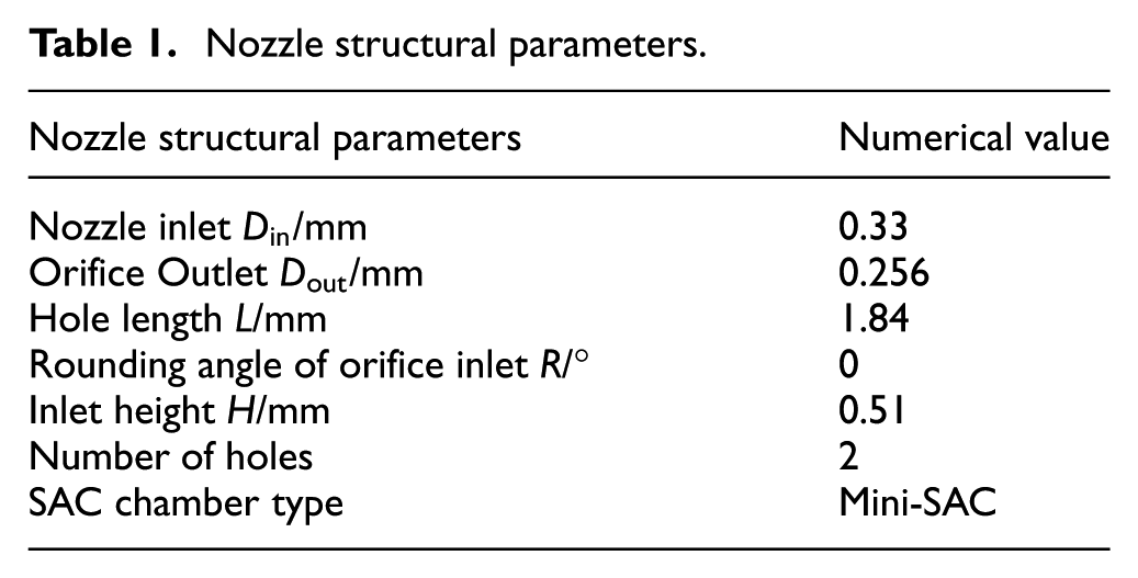
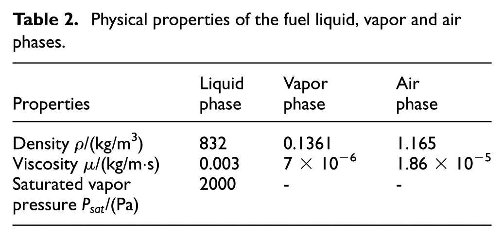
The baseline nozzle geometry follows our previous work, 53 as presented in Figure 1. The two nozzle orifices have a slightly tapered conical shape, which effectively suppresses wall-induced and cloud cavitation, thereby preventing these types of cavitation from interfering with the string cavitation of interest. This allows for a clear observation of the transient evolution of string cavitation within the orifices. With this configuration, this study investigates the effects of needle valve eccentricity, parameterized by eccentric distance and angle, on the internal flow and spray characteristics. The ranges of these structural parameters are shown in Table 1. The simulations used a working fluid exhibiting thermophysical properties similar to those of diesel fuel, with density and vapor pressure corresponding to industrial diesel at 303 K. The fluid properties parameters used in numerical calculations are shown in Table 2.
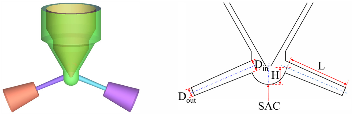
Schematic diagram of the reference nozzle.
Nozzle structural parameters.
Physical properties of the fuel liquid, vapor and air phases.
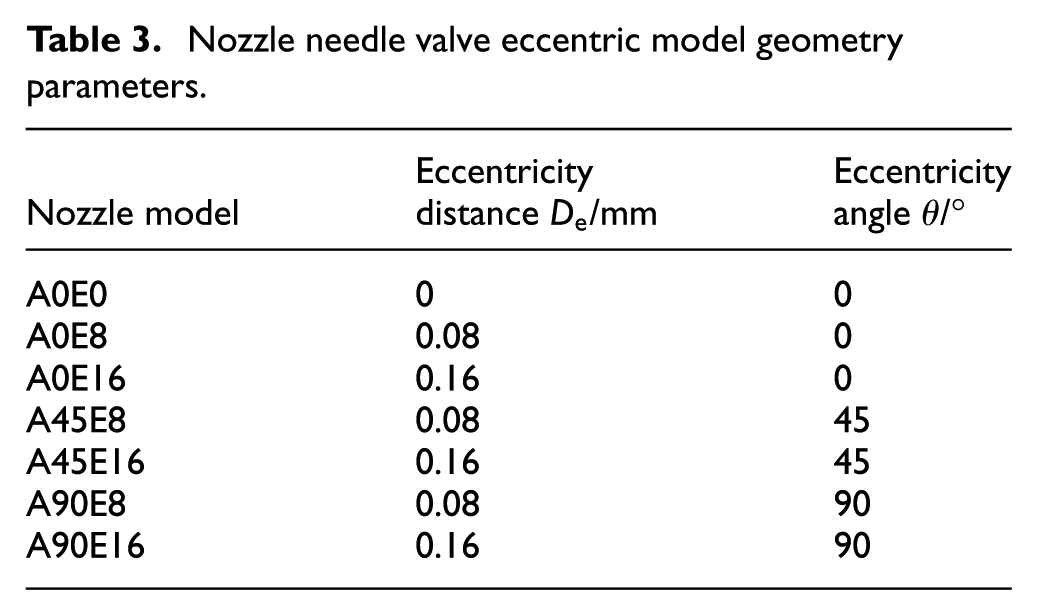
Using the prototype nozzle under fixed needle valve lift conditions, seven geometric models were generated by varying the needle valve eccentric distance and angle (Table 3). A Cartesian coordinate system was established in the top-view plane at the needle valve bottom, and the bottom-center position is shown in Figure 2.
Nozzle needle valve eccentric model geometry parameters.
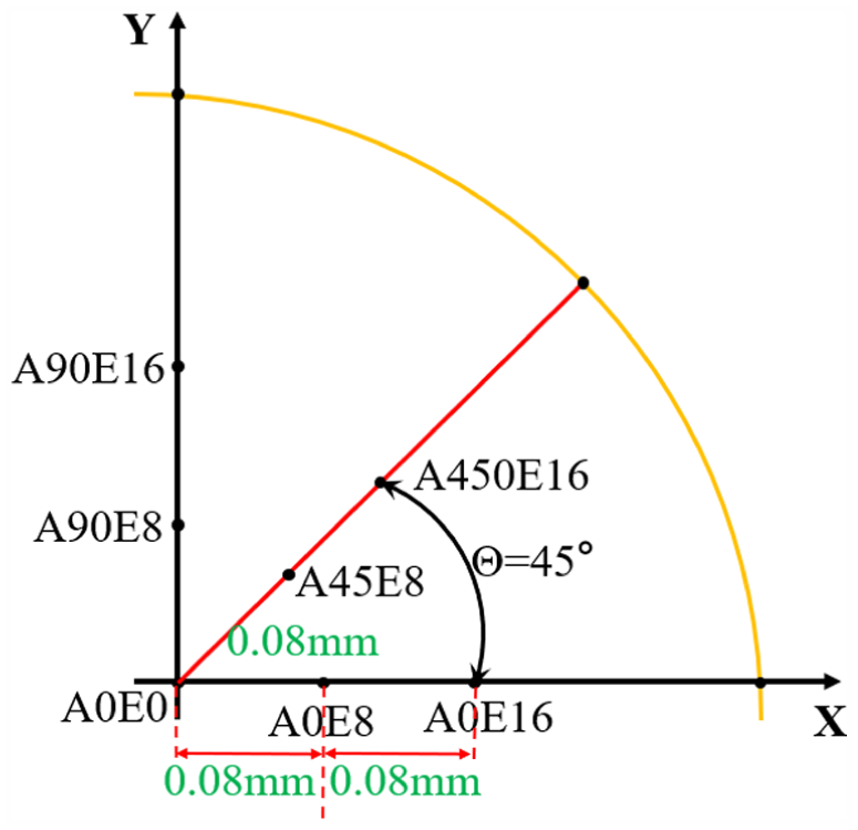
Schematic diagram of the eccentric position of the center point of the head of the fixed needle valve.
Numerical setup
Setting boundary and initial conditions is essential for ensuring the convergence and accuracy of numerical simulations. In this study, the boundary conditions consist of a constant upstream pressure inlet and a constant downstream pressure outlet. Following previous works,23,36 the injection pressure is set to 60 MPa, and the outlet backpressure to 0.1 MPa. Since pressure fluctuations in the high-pressure common rail pipe and upstream of the nozzle are relatively small, they are neglected. Additionally, appropriate initial conditions in the simulation help accelerate convergence to achieve a stable final flow field. Therefore, a relatively stable initial cavitating flow field is first obtained under steady-state conditions; subsequently, the simulations are switched to unsteady-state calculations to capture a stable, accurate, and periodically varying string cavitating flow field. Unsteady simulations start thereafter, with a time step of 3 × 10⁻⁸ s, and run for 0.5 ms to ensure about 90 times of the residence time of the flow inside the hole orifice, assuming an average velocity in the direction of the hole of 350 m/s for the given pressure drop of 60 MPa.
In the present work, the governing equations were solved using an implicit finite volume approach, with both spatial and temporal discretization implemented through a pressure-based solution algorithm. The Semi-Implicit Method for Pressure Linked Equations-Consistent (SIMPLEC) algorithm 54 is used to couple the solution of velocity and pressure. A first-order upwind scheme is applied for density, while the Reynolds stress terms are discretized using a second-order upwind scheme. For solving the momentum and phase volume fraction transport equations, the QUICK algorithm and compressive scheme are utilized, respectively. The pressure interpolation term is solved using the Modified Body Force Weighted format. The time term is discretized using a bounded second-order implicit format, which reduces temporal truncation error compared with a first-order scheme and thus more accurately captures the rapid phase transitions and high-frequency vortex shedding events characteristic of string cavitation, while the bounded formulation ensures numerical stability.
Validation of the numerical models
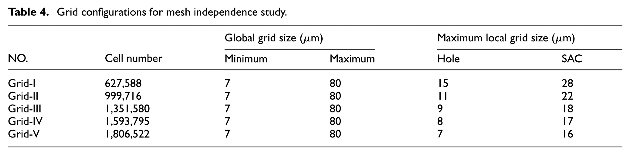
Prior to the main simulations, a grid resolution analysis is conducted based on the nozzle configuration with a centered needle valve to determine the optimal mesh size. As shown in Table 4, five different grid configurations with refined cells in the nozzle holes and sac regions are evaluated to ensure grid independence. The computational mesh for this configuration is generated using the ICEM platform, as shown in Figure 3. The computational grid regions of the nozzle geometric model are all constructed using high-quality structured hexahedral grids. Considering that the regions where string cavitation occurs and develops are primarily concentrated within the sac cavity and nozzle hole area, the grids in these computational regions are further refined. Additionally, a cylindrical spray chamber is added downstream of the nozzle outlet, moving the outlet boundary conditions away from the computationally sensitive regions within the nozzle, thereby enhancing the accuracy of the numerical simulation results.
Grid configurations for mesh independence study.
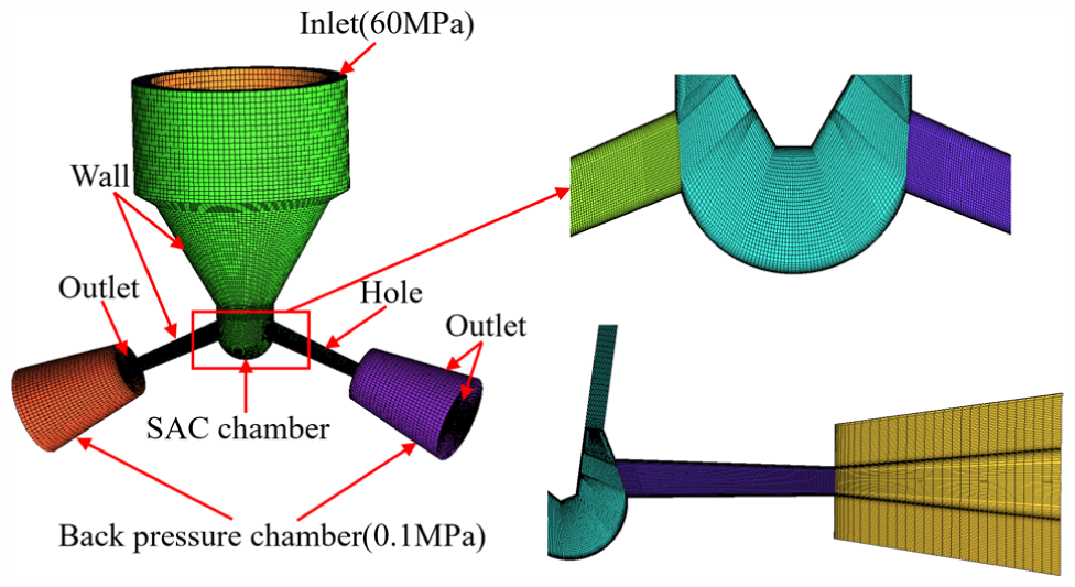
Computational mesh of the nozzle geometry (Grid-III configuration, 1.35 million cells).
Figure 4 shows the mesh independence analysis conducted under operating conditions of an inlet pressure of 60 MPa and an outlet pressure of 0.1 MPa. As the number of mesh elements increases, the nozzle grid can resolve a larger volume of vortex cavitation vapor, while the corresponding nozzle mass flow rate decreases. From a quantitative perspective, the computational Grid-III with 1.35 million cells provides the best compromise between computational efficiency and accuracy. Specifically, from Grid-III to Grid-IV, the relative change in mass flow rate is less than 0.8%, and the relative change in time-averaged vapor volume is within 2.3%, both satisfying the convergence criteria of <1% for mass flow rate and <3% for vapor volume. The maximum grid size corresponding to the nozzle hole is 15 µm. Therefore, based on the comparison of string cavitation patterns and mass flow rate results, the grid-III mesh is considered sufficiently reliable and accurate for all cases in this study. Figure 5 compares the distribution of string cavitation iso-surfaces obtained from the numerical simulation with the needle valve in the central position to the corresponding experimental data. In the simulations, string cavitation is primarily distributed within the sac cavity and near the nozzle outlet, which aligns well with the experimental imaging results.
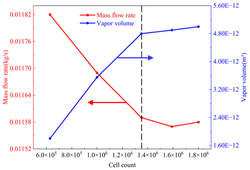
Effect of mesh resolution on mass flow rate and vapor phase volume.

Comparison of experimental and simulation results (numerical simulation is the equivalent surface of 10% volume fraction of the vapor phase).
Results and discussion
Eccentricity-induced cavitation morphology and volume fluctuations
Figure 6 presents the cavitation morphology for all seven eccentric configurations (where A denotes the eccentric angle in degrees and E denotes the eccentric distance in units of 0.01 mm; see Table 3 for details). Figure 6(a) shows iso-surfaces of vapor volume fraction (α = .1) for each model; Figure 6(b) and (c) display the cross-sectional distributions of pressure, vapor volume fraction, and mass transfer rate at the left and right nozzle hole mid-planes, respectively. As shown in Figure 6, needle valve eccentricity causes significant changes in the cavitation morphology within the nozzle. In the reference geometry A0E0, the cavitation zones on both sides of the nozzle are symmetrical and slightly converge along the nozzle axis, forming a uniform cavitation layer. When X-axis eccentricity is introduced (A0E8, A0E16), the cavitation zone on the eccentric side of the nozzle expands significantly, while that on the non-eccentric side is compressed. With increasing eccentricity, the asymmetry becomes more pronounced, and the eccentric side in A0E16 exhibits stronger cavitation intensity. For eccentricity at 45° (A45E8, A45E16), a similar trend is observed, and the initial cavitation region shifts when the eccentric distance reaches 0.16 mm. For Y-axis eccentricity (A90E8, A90E16), cavitation in both holes remains approximately symmetrical, but cavitation intensity in the nozzle midsection is significantly weakened. Cross-sectional views in Figure 6(b) and (c) show that vortex rotation reduces the pressure at the vortex core relative to the surrounding area, resulting in the formation of elongated string cavitation columns near the core. Simultaneously, a comparison of mass transfer rates reveals that the needle-side string cavitation near the needle valve is unstable and accompanied by stronger vaporization, whereas the hole-side string cavitation between the two nozzles maintains a dynamic equilibrium between vaporization and condensation. In the reference geometry A0E0, a typical axial annular string cavitation structure forms from below the needle valve into the interior of the nozzle. This structure consists of a series of disk-shaped cavitation nuclei distributed along the nozzle axis, accompanied by local low pressure and periodic vaporization-condensation cycles. Correspondingly, the mass transfer rate exhibits a positive peak (evaporation) at the cavitation nuclei and a negative value (condensation) in the downstream pressure recovery zone, indicating that bubble formation and collapse are primarily confined to the vicinity of the vortex nuclei and exhibit periodic behavior.
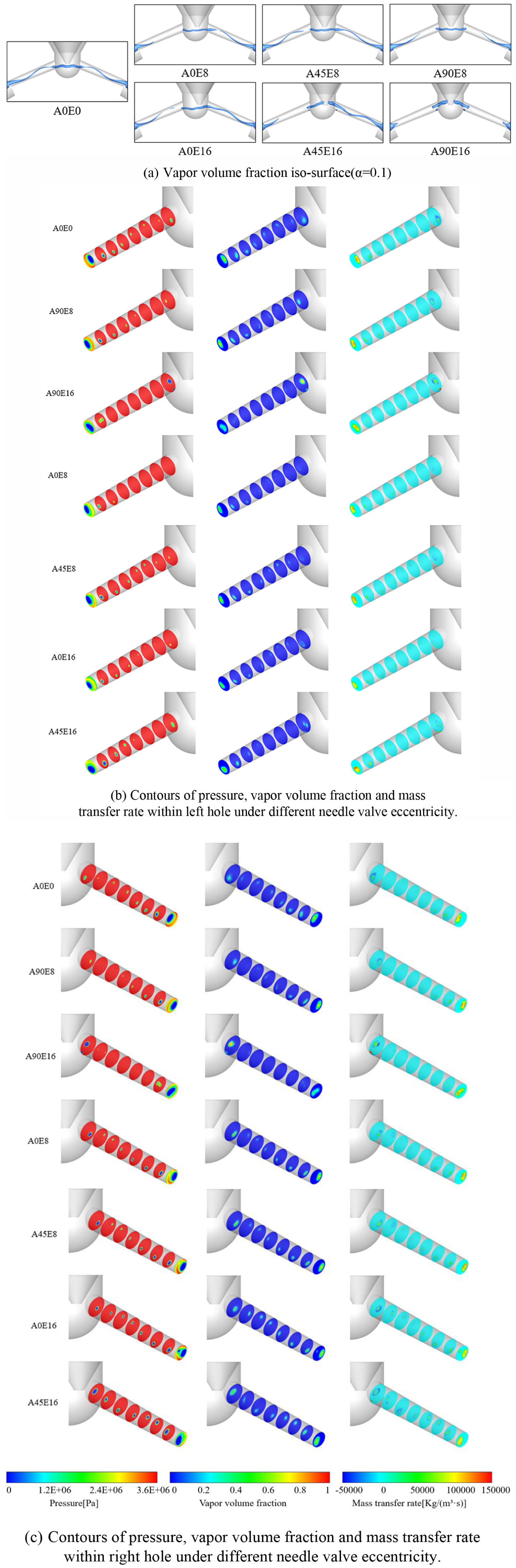
Different needle valve eccentric configurations; (a) iso-surface plot of vapor volume fraction (α = 0.1), (b) distributions of pressure, vapor volume fraction, and mass transfer rate at the left nozzle cross-section, and (c) distributions of pressure, vapor volume fraction, and mass transfer rate at the right nozzle cross-section.
Needle valve eccentric distance enhances cavitation intensity inside the nozzle and alters the distribution and stability of the cavitation region. As the eccentric distance increases from 0.08 to 0.16 mm, the local minimum pressure inside the nozzle further decreases. Meanwhile, both the peak vapor volume fraction and the overall cavitation percentage increase. The peak mass transfer rate increases with a broader distribution, indicating that a larger portion of the liquid volume undergoes vaporization. The asymmetric flow channel induced by needle valve eccentric distance increases the flow velocity on the narrower channel side and causes a sudden pressure drop, facilitating vortex-induced vaporization. Meanwhile, the strong lateral pressure gradient and shear force promote vortex nucleation and detachment, resulting in stronger cavitation nuclei that are closer to the wall. The eccentricity angle controls the direction of cavitation displacement. Under different eccentricity angles, cavitation in the left and right holes exhibits symmetric or asymmetric distribution, determining which side first experiences high-speed jet contraction and strong vortex detachment. Consequently, cavitation is stronger in the right hole than that in the left hole under certain operating conditions. The mass transfer rate further indicates that greater eccentricity intensifies the evaporation–condensation alternation, exacerbating the cavitation–collapse cycle and leading to stronger transient pressure pulsations as well as increased risks of noise. In summary, Figure 6 demonstrates that needle valve eccentricity amplifies cavitation effects within the nozzle and renders them asymmetric and unstable, laying the foundation for subsequent analysis.
To quantify cavitation instability, the cavitation fluctuation amplitude is defined as a normalized relative fluctuation index:
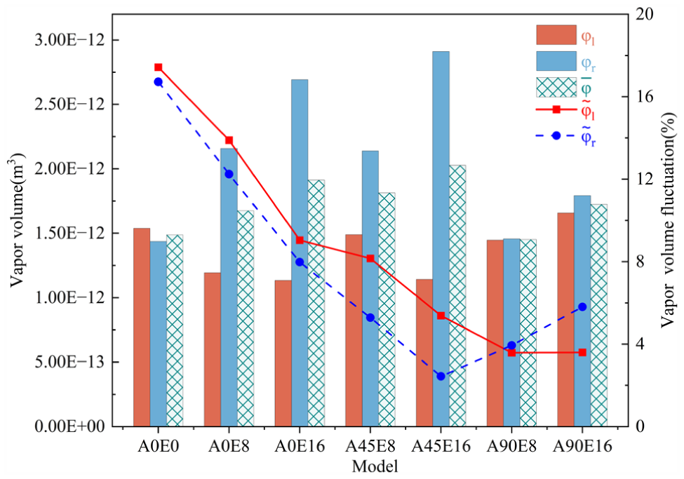
Vapor volume fraction and vapor volume fraction fluctuation diagrams.
As shown in Figure 7, moderate eccentricity of the needle valve helps reduce cavitation instability. Specifically, when the eccentric angle is 45° and the eccentric distance is small (e.g. A45E8), the growth and collapse of bubbles within the cavitation zone occur most smoothly and continuously, resulting in the lowest cavitation oscillation amplitude, indicating the most stable cavitating flow. Conversely, when the eccentricity angle is 0° (indicating that the center lines of the needle valve and nozzle are aligned) or when eccentricity is entirely absent, the violent cycle of bubble nucleation, expansion, and collapse characterized by high-amplitude oscillations dominates.
The asymmetric cavitation distribution and enhanced cavitation instability induced by needle valve eccentricity (detailed in Section 3.1) directly modulate the nozzle’s flow behavior—specifically, the non-uniform cavitation zones alter the effective flow area and velocity distribution of the nozzle, which in turn impacts the flow capacity (characterized by flow coefficient) and flow stability. These effects of cavitation on nozzle flow performance are systematically analyzed in Section 3.2.
Effects of cavitation on nozzle flow capacity and stability
The flow coefficient is an important indicator for measuring the flow characteristics of a nozzle and is also a key focus in nozzle product design. Figure 8 shows the time-averaged flow coefficient at the nozzle outlet under different eccentric models. The eccentric configurations follow the notation defined in Table 3 (where A denotes the eccentric angle in degrees and E denotes the eccentric distance in units of 0.01 mm). The definition of the time-averaged flow coefficient is as follows:


where
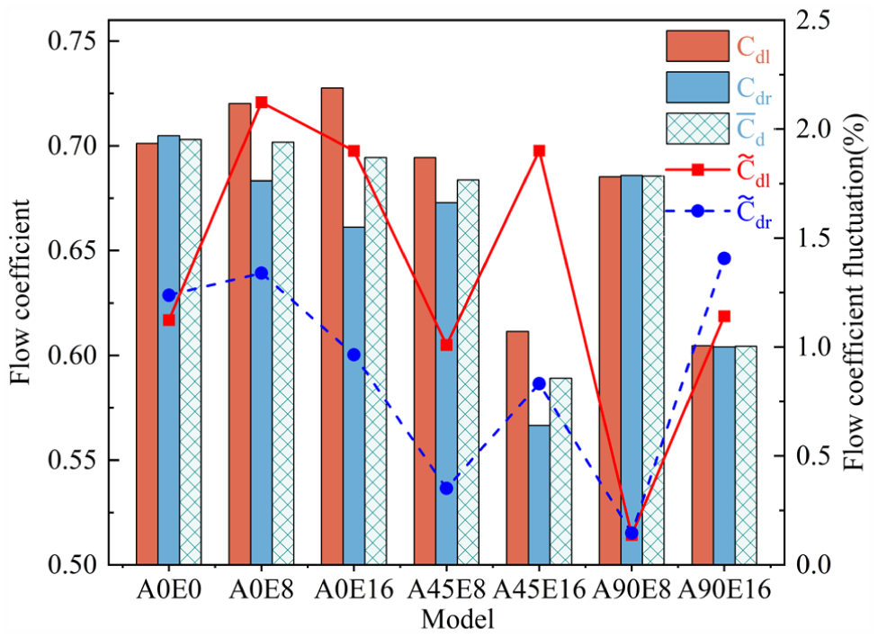
Nozzle flow coefficient and flow coefficient fluctuation diagrams.
Figure 8 presents flow coefficient under different eccentric configurations: solid lines represent the flow coefficient fluctuation amplitude of left nozzle hole
Figure 8 shows that needle valve eccentricity not only reduces the flow coefficient of the nozzle but also affects flow stability. Overall, as the eccentricity parameter deviates from the center, the nozzle’s flow capacity decreases (average flow coefficient decreases); in extreme eccentricity cases (such as A45E16 and A90E16), due to severe throttling on one side of the nozzle orifice and strong cavitation, the flow coefficient significantly decreases, demonstrating that eccentricity degrades the nozzle’s delivery efficiency. However, moderate eccentricity (especially small eccentricity along the closed wall) helps reduce flow pulsation fluctuations and improve flow stability. In the practical application of fuel injectors, the effect of unavoidable eccentricity can be considered acceptable when the magnitude of this eccentricity is below 0.08 mm.
While Section 3.2 clarifies the macro-scale effects of eccentricity-induced cavitation on flow coefficient reduction and flow instability, the underlying physical mechanism driving these phenomena—that is, how needle valve eccentricity regulates the interactions between vortex structures, cavitation evolution, and phase transitions—remains to be elucidated. Section 3.3 therefore focuses on the coupling mechanism of vortex-cavitation-phase transition under eccentricity, aiming to reveal the intrinsic link between geometric eccentricity and the observed flow performance variations.
Vortex-cavitation-phase transition coupling mechanism under eccentricity
The cavitating flow inside diesel injector nozzles is turbulent, and the Reynolds Stress Model can simulate in-nozzle vortices with reasonable accuracy. To further analyze the distribution of vortex structures in the nozzle hole and spray zone, the third-generation Omega vortex identification method 37 is employed to capture flow field vortices. The specific definition is as follows:






Where
The
Under the reference geometry A0E0 (concentric needle, where A denotes the eccentric angle and E the eccentric distance; see Table 3), the internal nozzle vortex structure is simple and uniform, with a single streamwise vortex dominating the flow, which spans from the bottom of the needle valve to the nozzle hole. This streamwise vortex is a prerequisite for string cavitation. Additionally, when cavitation approaches a periodic steady state, a pair of secondary vortices rotating in the same direction appear in the SAC cavity downstream of the needle valve. These vortices converge near the nozzle orifice entrance, weakening the main longitudinal vortex. Due to the angle between the nozzle axis and the nozzle hole axis, downstream flow is affected by wall obstruction. As shown in Figure 9, the vortex intensity near the nozzle hole wall weakens, resulting in reduced vortex string cavitation in the middle section. However, due to the conical structure of the nozzle contraction and the conservation of angular momentum, the swirl intensity along the nozzle axis gradually increases, causing the string cavitation intensity to reach its maximum near the nozzle outlet. Compared to the non-eccentric case, as the eccentricity increases, the vortex pattern becomes asymmetrical and complex: the vortex intensity on the eccentric side (one side) increases, and the vortex core distribution in some models (such as A0E8, A0E16, A45E8) no longer exhibits symmetrical and regular vortex core distributions, and the secondary vortices generated on the eccentric side gradually merge into the main vortex; on the side far from the eccentricity, since the secondary vortices are farther from the nozzle inlet, they cancel out with the main vortex in the SAC cavity until they disappear, consequently, the vortices at the nozzle inlet on this side do not receive the enhancing effect of inlet contraction, further weakening the cavitation intensity of the strings deviating from the nozzle. When the eccentric angle is 45° or 90° and the eccentric distance is large (A45E16, A90E16), the “hole” string cavitation transforms into “needle” string cavitation (i.e. the vortex core shifts toward the gap between the nozzle and the outer wall), and no paired secondary vortices are generated. Although cavitation within the SAC cavity remains intense at this point, the local geometry at the nozzle inlet undergoes significant changes, leading to the formation of complex vortex structures such as separation vortices and secondary vortices, resulting in a more turbulent and unstable flow field. Furthermore, by comparing the iso-surfaces of the Ω vorticity criterion (Figure 9(a)) with the cavitation gas phase distribution (Figure 6(a)), it can be observed that the positions of the cavitation cavities in all models highly align with the regions where strong vortex nuclei are present, supporting the dominant mechanism of “vortex-induced cavitation,” where the low pressure at the core of strong vortices is the primary cause of cavitation.
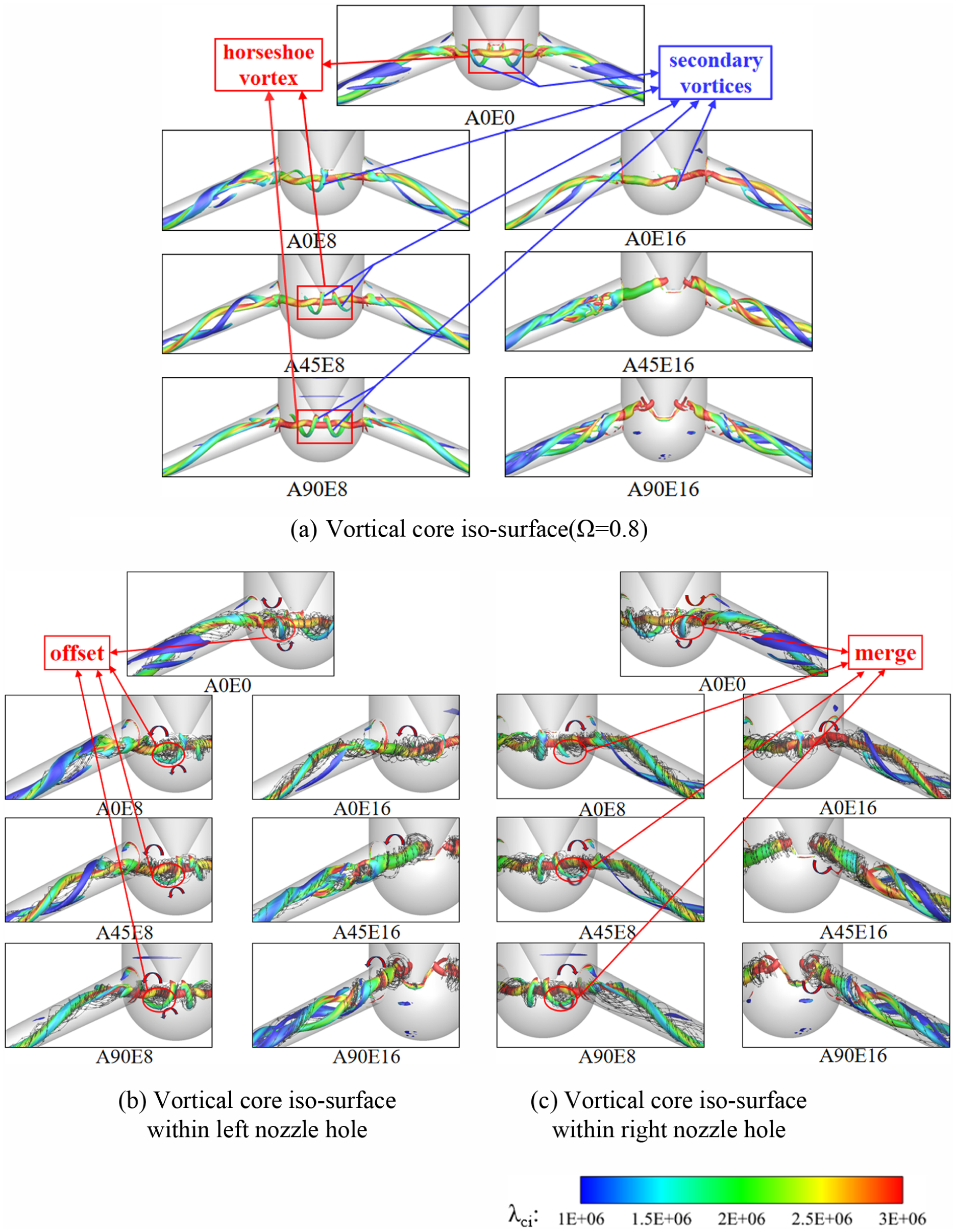
Comparison of different eccentricity models: (a) vortex core contour map (Omega = 0.8), (b) vortex core contour map and streamline diagram of the left nozzle hole, (c) vortex core contour map and streamline diagram of the right nozzle hole.
Figure 9 clearly shows that the eccentricity of the needle valve significantly regulates the vortex structure and cavitation morphology of the nozzle. Eccentricity alters the original symmetrical vortex distribution: on the eccentric side, it strengthens the main vortex and absorbs the secondary vortex, while on the other side, it weakens or even eliminates the secondary vortex. This explains why the cavitation region shifts to one side or moves closer to the wall. In particular, a larger eccentricity along the closed wall causes the ring-shaped horseshoe vortex in the SAC cavity to weaken or disappear. The originally symmetrically constrained vortices at the nozzle inlet are not enhanced but instead disrupted by the wall and geometric changes, leading to the formation of complex structures such as separation vortices, thereby increasing flow instability. Additionally, the correspondence between vortex nuclei and cavitation demonstrates that strong vortices induce local vaporization. The eccentricity of the needle valve indirectly influences cavitation generation and development by affecting vortex intensity and position. This result reveals how eccentricity alters vortex structure to influence cavitation behavior, exacerbating unstable flow within the nozzle on a macroscopic scale.
The enhanced vortex-cavitation-phase transition coupling under eccentricity (elaborated in Section 3.3) directly distorts the flow field at the nozzle outlet—specifically, the asymmetric vortex distribution and cavitation migration modify the outlet velocity uniformity and vapor fraction, which further impacts the subsequent spray atomization quality. Section 3.4 thus focuses on the outlet flow characteristics of eccentric nozzles and their implications for spray atomization, bridging the gap between internal flow dynamics and downstream spray performance.
Outlet flow characteristics and implications for spray atomization
Figure 10 reveals the significant influence of the needle valve eccentricity on the evaporation-condensation process within the nozzle (where A denotes the eccentric angle in degrees and E denotes the eccentric distance in units of 0.01 mm). Overall, all models exhibit a peak evaporation rate near the nozzle outlet, indicating that cavitation bubbles primarily vaporize at the outlet. The evaporation rate at the outlet cross-section is approximately 10 times higher than that at other internal positions of the nozzle. In the middle section of the nozzle, the mass transfer rate curves for all models approach zero, indicating that vaporization and condensation tend toward equilibrium in this region. This aligns with the previously observed “breaking” phenomenon of string cavitation in the nozzle midsection, where the dynamic vapor-liquid equilibrium induces the interruption of the cavitation cavity. When comparing different eccentricities, the curve for A0E0 (non-eccentric reference) in the left nozzle hole (corresponding to Figure 10(a)) is the smoothest, with uniform evaporation and condensation indicating stable flow in the left hole. As eccentricity increases, the curve for A0E16 exhibits the most significant fluctuations, with noticeable variations in axial distribution. Although the peak is reached at the outlet, the peak value is relatively low, meaning that while evaporation intensity fluctuates greatly at maximum eccentricity, the peak vaporization rate actually decreases. In the right nozzle hole (Figure 10(b)), the trends of all models are similar to those of the left nozzle: A0E0 is smooth and uniform, while A0E16 exhibits significant fluctuations and reaches the highest peak at the outlet, indicating that the right nozzle exhibits very intense evaporation phenomena at the outlet under eccentricity conditions. Except for extreme cases, other eccentric models differ little in curve shape, suggesting that eccentricity primarily affects the intensity and fluctuation amplitude at the maximum vaporization position, while trend changes in the mid-section are relatively limited.
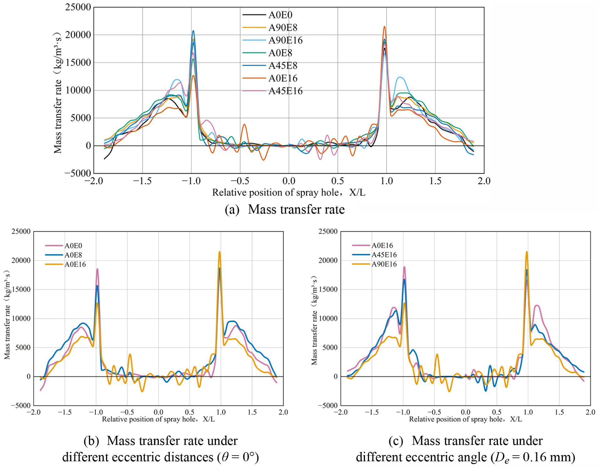
Comparison of average mass transfer rate distributions in the nozzle and backpressure chamber for (a) different needle valve eccentricity models, (b) different eccentricity distance models (
Figure 10 shows that eccentricity synchronously enhances the vaporization and condensation processes within the nozzle. As eccentricity increases, both the intensity and frequency of two-phase mass transfer significantly increase, manifested by more pronounced fluctuations in the mass transfer rate curve, higher peaks, or broader peak extensions. Especially at the nozzle outlet, all eccentric models exhibit stronger vaporization tendencies (higher evaporation peaks) compared to the non-eccentric model. Therefore, eccentricity in the needle valve causes more intense vaporization and more frequent bubble formation/collapse in localized regions within the nozzle (particularly at the outlet), further explaining why cavitation instability increases under eccentric conditions. This eccentricity-induced enhancement of evaporation/condensation may have significant implications for the spray process. For instance, to maintain the cavitation of the upstream-formed string through to the outlet, one may consider adjusting the cavitation model parameters to reduce condensation in the mid-section or increase the evaporation rate. Overall, eccentricity alters the distribution of cavitation phase transition rates along the flow path, making cavitation intensity more pronounced at the outlet end and thereby amplifying its impact on downstream spray behavior.
Figure 11 illustrates the effect of cavitation within the nozzle on the initial flow field of the jet: all models exhibit a distinct central low-speed region, high-speed peripheral regions, and a rotating jet structure at the nozzle outlet. Specifically, in the central region of the nozzle outlet, the arrows are short and densely packed, indicating lower flow velocity and smoother flow; near the peripheral regions of the outlet, the arrows are longer, indicating higher flow velocity and more complex flow patterns, with significant tangential rotation and turbulent characteristics. This suggests that as fuel flows through the nozzle, the flow near the central axis slows down due to a gradual pressure increase, while the flow near the nozzle inner edges forms high-speed jets driven by flow contraction and shear effects from the needle-valve-to-nozzle-wall gap. The distribution of velocity vectors indicates that the ejected liquid flow exhibits distinct vortices (i.e. swirl flow), which facilitates fuel-air mixing. However, overly strong or unstable vortices may reduce combustion efficiency. In terms of color, as the distance from the outlet plane increases downstream, the fuel vapor volume fraction gradually increases, indicating that liquid fuel continuously evaporates and transforms into a gaseous state during the jet process. High vapor content regions are often accompanied by higher jet velocities, reflecting the significant influence of evaporation on jet dynamics: fuel vaporization reduces local density and triggers stronger gas flow movements, thereby forming more complex flow structures. Comparisons of different models reveal: When the eccentricity is small (e.g. A0E0, A0E8, A0E16, A45E8, A90E8), the jet distributions from both sides of the nozzles are relatively symmetrical and uniform, with a distinct low-speed zone at the center and good symmetry of the spray cone. However, when the eccentricity angle or distance is large (A45E16, A90E16), the spray spatial distribution exhibits significant asymmetry: the gas phase content and velocity field of the jet emitted from one side differ from those of the other side. Typically, regions with high vapor volume fractions indicate sufficient fuel evaporation and a high gas phase ratio. However, in A45E16 and A90E16, despite the overall high vapor generation in these models, lower local velocities and reduced vapor volume fractions are measured near regions where gas phase accumulation occurred. This suggests that under highly eccentric conditions kinetic energy is redistributed from the large-scale mean flow into high-frequency, small-scale turbulent fluctuations that dissipate rapidly. Small-scale turbulence cannot compensate for the loss of coherent momentum needed for effective droplet breakup. While evaporation occurs, it fails to fully atomize the fuel, resulting in localized liquid phase enrichment. This may lead to the presence of under-atomized or oversized droplets within the spray.
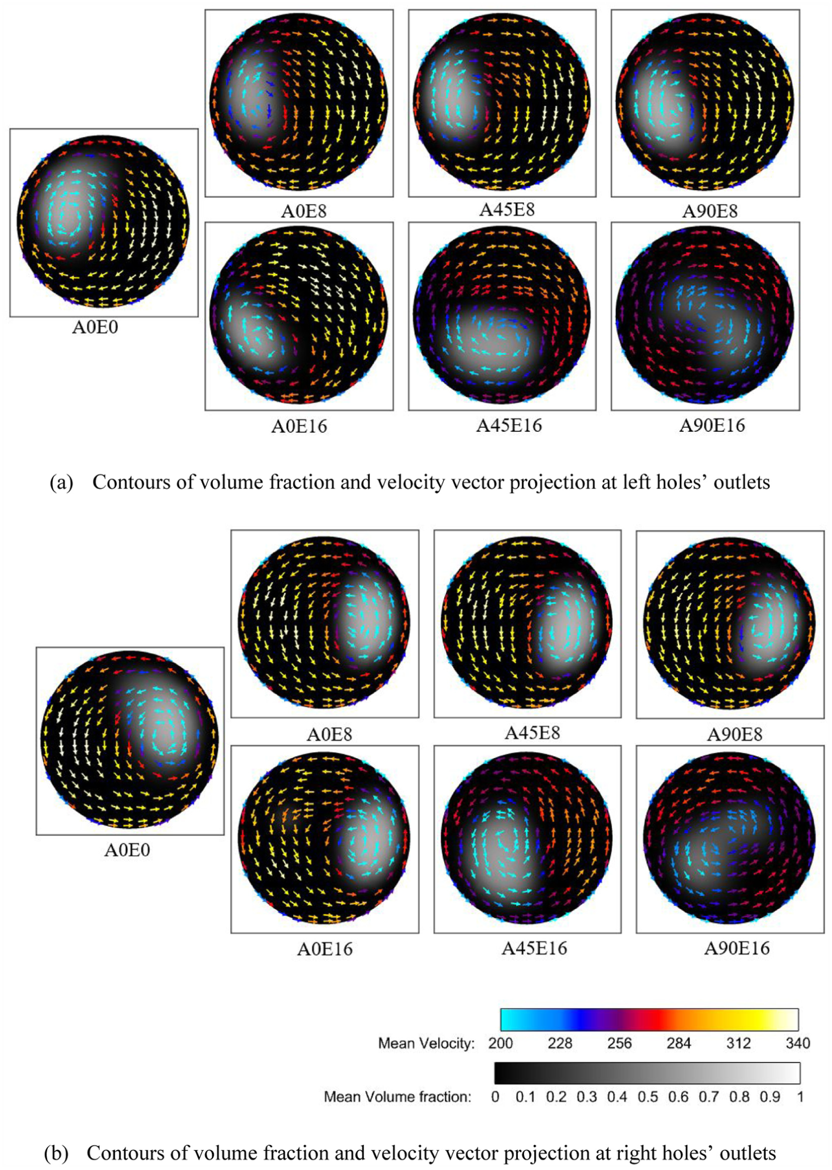
Contours of volume fraction and velocity vector projection at holes’ outlets under different eccentric models for (a) left nozzle hole and (b) right nozzle hole.
Figure 11 shows that the eccentricity of the needle valve affects the structure of the fuel jet at the nozzle outlet, which may have potential implications for subsequent spray formation and combustion. When the eccentricity is small or absent, the jet flow field remains uniformly symmetrical, with normal distribution of the central recirculation zone and peripheral high-speed zone, ensuring adequate evaporation and uniform spray distribution, which is conducive to stable combustion. However, in models with significant eccentricity, the spray becomes skewed and uneven: cavitation-induced vortex flow is weakened and disrupted at the outlet surface, spray symmetry deteriorates, local vaporization is insufficient, and large droplets or dense mixture clusters may form, leading to unstable atomization. Therefore, excessive needle valve eccentricity reduces spray quality and increases the risk of incomplete combustion. In injector design, extreme eccentricity-induced spray asymmetry must be avoided to ensure good atomization and combustion performance.
Figure 12 comprehensively illustrates the trend of eccentricity’s influence on the internal dynamics of the nozzle. As shown in Figure 12(a), the cavitation intensity along the axial direction of the left and right nozzle holes exhibits a consistent pattern, with relatively high cavitation intensity at the midpoint, followed by a decrease in the downstream section due to the conical contraction geometry, and then a rapid and significant increase near the nozzle outlet as the conservation of angular momentum enhances swirl intensity along the nozzle axis. More specifically, there is a decrease in cavitation intensity at the midpoint of the nozzle hole (interruption of the cavitation cavity) and a slight increase near the outlet. This is consistent with the previous analysis: cavitation along the string always ceases in the central region of the hole. This is because, on the one hand, the lateral momentum carried by the fuel entering the nozzle from upstream is converted into swirling motion, enhancing the vorticity; on the other hand, at the conical nozzle outlet, higher vorticity and axial velocity occur due to the conservation of angular momentum, leading to weakened cavitation in the middle section and an increase in cavitation intensity near the outlet. As shown in Figure 12(b), the average vorticity within the nozzle increases significantly with increasing eccentricity, particularly at an eccentricity of 0.16 mm, indicating that eccentricity promotes more intense rotation of the flow field and increased secondary flow. Among the models, the A45E16 and A90E16, which have the largest eccentricity, exhibit the greatest increase in vorticity. The vorticity trends of the left and right nozzle holes are similar with respect to eccentricity, but under certain eccentricity conditions, the vorticity of the right hole is slightly higher than that of the left hole, indicating that the flow in the right hole is more complex and may form more small vortex structures. The trends of turbulent kinetic energy and vorticity in Figure 12(c) are similar, with turbulent kinetic energy significantly increasing with increasing eccentricity. Especially in A45E16 and A90E16, the turbulent kinetic energy levels are far higher than in other operating conditions, indicating that strong eccentricity causes extremely intense and unstable internal flow. Turbulent kinetic energy (TKE) increases most significantly in the nozzle inlet region (0 <
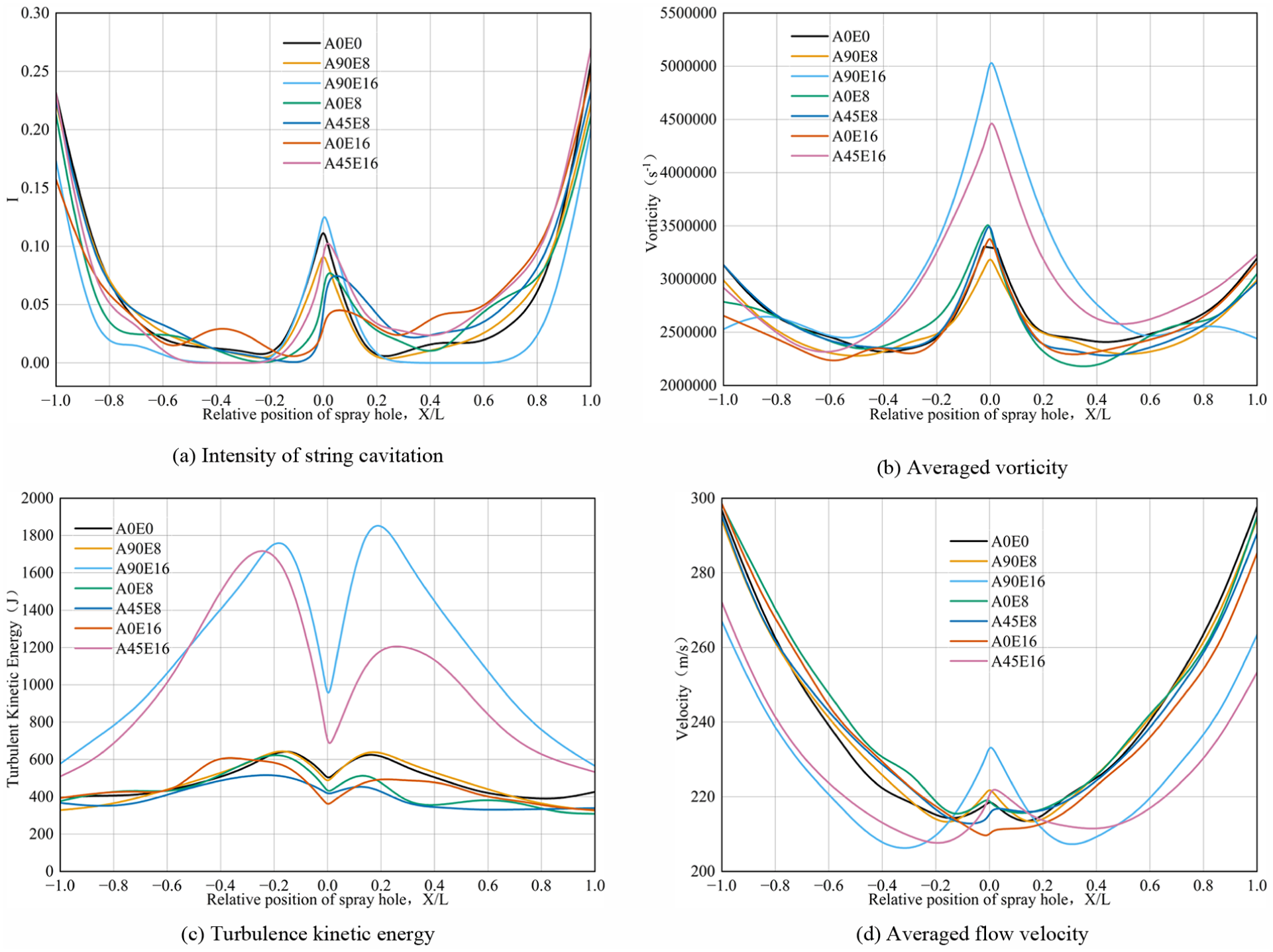
Local flow characteristics of nozzle holes under different eccentricity models: (a) string cavitation intensity, (b) average vorticity, (c) turbulent kinetic energy, and (d) average flow velocity (The negative sign indicates the left side).
Figure 12 summarizes the changes in cavitation and vortex intensity as well as turbulence levels under various eccentric conditions, demonstrating that eccentricity significantly alters the flow characteristics inside the nozzle. The channel asymmetry introduced by eccentricity increases cavitation intensity, vortex strength, and turbulence energy, leading to more unstable internal flow. Specifically, the eccentricity parameter influences the continuity (interruption or otherwise) of cavitation along the string, the generation and disappearance of vortices, and the distribution of cavitation bubble strength. When the eccentricity is large and directed along the wall surface, certain vortices that previously maintained flow field equilibrium (such as horseshoe vortices) are weakened or eliminated, replaced by more complex new vortex systems, thereby exacerbating flow field fluctuations. Additionally, eccentricity significantly alters the spatiotemporal characteristics of vaporization/condensation within the nozzle (see Figure 10), thereby weakening the original vortex and cavitation effects at the nozzle outlet. These changes ultimately manifest in spray atomization quality: large eccentricity reduces spray axial symmetry and fine atomization degree (Figure 11), potentially leading to localized combustion instability or efficiency reduction. Therefore, the common conclusion from the parameters shown in Figure 12 is that needle valve eccentricity intensifies cavitation and turbulent vortices, making the flow inside the nozzle more violently unstable, and has a comprehensive impact on the nozzle’s flow capacity and spray performance. This provides quantitative evidence for understanding the coupled mechanism of eccentricity-vortex-cavitation.
The preceding sections (3.1–3.4) have sequentially elucidated the cascade effects of needle valve eccentricity: from inducing asymmetric cavitation and volume fluctuations (3.1), to reducing flow coefficient and destabilizing flow (3.2), to regulating the vortex-cavitation-phase transition coupling (3.3), and finally to distorting outlet flow and impairing spray atomization (3.4). Section 3.5 further integrates these findings into a comprehensive causal framework, discusses the limitations of the current study, and proposes directions for future optimization of nozzle design.
Conclusions
In this study, we conducted a systematic analysis of how eccentric parameters affect string cavitation morphology, vortex structure, evaporation/condensation processes, and internal nozzle flow performance. The analysis employed the VOF multiphase flow model, modified ZGB cavitation model, and Reynolds Stress Model, and was supported by grid independence verification and transient numerical simulations of seven eccentric needle valve geometries. This study identified the intrinsic coupling mechanisms among eccentricity, asymmetric cavitation distribution, vortex enhancement, cavitation instability, and flow coefficient changes, leading to the following conclusions:
Needle valve eccentricity causes a significant asymmetric distribution of cavitation inside the nozzle and can induce migration of the cavitation initiation zone. As the eccentric distance increases (0, 0.08, 0.16 mm) and the eccentric angle changes (0°, 45°, 90°), the vapor phase volume distribution on both sides of the nozzle shifts from symmetric to asymmetric. It also changes the cavitation type from inter-hole string cavitation to needle-hole string cavitation. Notably, 90° eccentricity (e.g. A90E8) maintains a low deviation rate (<0.1), alleviating asymmetric cavitation.
Eccentricity enhances vorticity and turbulent kinetic energy in the main flow region, leading to stronger cavitation-vortex coupling and greater instability. On the eccentric side of the nozzle, the vortex core intensity is enhanced, with secondary vortices incorporated into the main vortex. Overall vorticity and turbulent kinetic energy increase with increasing eccentricity, increasing cavitation breakup frequency and vaporization-condensation cycling frequency. The “cavitation interruption” phenomenon observed in the middle section becomes more pronounced, thereby exacerbating transient fluctuations in the internal flow field.
Needle valve eccentricity significantly impacts flow capacity: severe eccentricity reduces the nozzle flow coefficient by approximately 1%–17% compared with the reference geometry A0E0, with the maximum reduction of 17% observed for A45E16 (45°, 0.16 mm). This corresponds to an effective flow area reduction of 12%–14% and an increase in the velocity non-uniformity index up to 0.35. Conversely, mild eccentricity along the nozzle’s closed wall (e.g. A90E8) suppresses cavitation volume fluctuation amplitude by 78% compared with A0E0, effectively stabilizing the flow.
Controlling needle valve eccentricity suppresses detrimental cavitation, while excessive eccentricity should be avoided. By altering vapor volume distribution, vortex velocity field, and outlet velocity profile, eccentricity directly impacts spray quality: mild 90° eccentricity reduces cavitation oscillations and enhances spray stability; excessive eccentricity (e.g. A45E16) causes severe outlet unevenness, inducing localized incomplete atomization and accelerating nozzle component wear, thereby impairing combustion efficiency. This study focuses on fixed needle lift; future work should explore dynamic lift and wall roughness effects. Thus, nozzle design should balance moderate eccentricity’s stabilizing effect with flow efficiency for optimized performance and reliability.
In summary, needle valve eccentricity fundamentally alters the internal cavitating flow field by inducing channel asymmetry, enhancing vorticity and flow separation, and triggering asymmetric cavitation that disrupts the velocity and vapor distribution at the nozzle outlet. These effects ultimately reduce spray symmetry and may impair combustion efficiency. This study is limited to a fixed needle lift and a two-hole nozzle geometry; future investigations should consider dynamic needle lift conditions to evaluate transient eccentricity effects, extend the framework to multi-hole nozzle geometries, and explore active mitigation strategies such as optimized inlet rounding, nozzle hole angle adjustments, and spinning jet impingement techniques. 59 Additionally, the ZGB cavitation model assumes a constant bubble radius (0.001 mm), which neglects bubble size evolution; future models incorporating variable bubble dynamics should be explored. Coupling the present framework with spray combustion simulations would enable a more comprehensive assessment of eccentricity effects on engine performance.
Footnotes

Funding
The authors disclosed receipt of the following financial support for the research, authorship, and/or publication of this article: This work was supported by funding from the National Natural Science Foundation of China (No. 52376113 and No. 52106153).
Declaration of conflicting interests
The authors declared no potential conflicts of interest with respect to the research, authorship, and/or publication of this article.
Data availability statement
The data supporting the findings of this study will be available on request. Interested researchers can contact the corresponding author for access.*