
Abstract
To correct the balance of the rotating assembly of a turbocharger, some parts of the compressor wheel are removed by cutting. A numerical investigation of the turbulent flows and flow noises produced by compressor wheels modified with such cutting parts was performed by a turbulence model and detached-eddy simulations. For the 6-cutting case, 0, 2, 4, and 6 circular cuttings and two additional—rectangular and triangular—shapes were used.
To investigate the effects of the balance cuttings in a compressor wheel, the evaluation process using computational fluid dynamics was tried. It was found that the fluid forces due to the various wheel shapes have the potential to restore the eccentricity by approximately 50%. Severe variations of velocity, pressure, and turbulent kinetic energy in the interspace between the wheel and volute were observed. In particular, the wavelike patterns of pressure and turbulent kinetic energy were intensified for the modified wheels. The turbulent kinetic energy of the 6-cutting case had a dominant frequency at approximately 3000 Hz. The spectrum of the sound-pressure level of the modified compressor wheels exhibited the features of buzz-saw noise. The flow fields suggested that this feature of the sound pressure is related to the tip-clearance flow affected by the balance cuttings. In addition, the acoustic pressure and flow characteristics of the different types of modified compressor wheels were discussed and the resulting acoustic power was evaluated.
Introduction
Turbochargers have frequently been adopted in automotive applications to increase the output power of an engine by boosting the intake air pressure. A turbocharger consists of a compressor wheel and an exhaust-gas turbine wheel. The turbine power is extracted from the engine’s exhaust gas and used to drive the compressor. The resulting compressed air is additionally forced into the combustion chamber. The increased density of the intake air improves combustion efficiency, providing some benefit in power and fuel consumption. Therefore, it is advantageous to use a turbocharger during engine downsizing to reduce the CO2 and NO2 air pollutants. 1
A literature survey shows that many studies are using computational fluid dynamics (CFD) to improve the performance of turbochargers. Abdelmadjid et al. 2 investigated compressor performance for three designs with different volute geometries. They found that different volute inlets change the peak efficiency and the operating range is affected by the change in shape of the volute cross-section. Yang et al. 3 investigated the influence of the cross-sectional shape of the volute on turbine performance under pulsating conditions. They found that the volute shape is sensitive to the pulsating flows and produces strong flow distortions. Roclawski et al. 4 evaluated the transient performance of a turbocharger using CFD. They explored the flow fields and turbine performance of a load-step simulation of a radial turbine. These studies are related to the shape design of turbochargers under steady and unsteady conditions. In the current study, CFD is used to investigate the flow-induced noise produced by unbalanced compressor wheels.
Since a compressor wheel is usually manufactured by a casting process, an imbalance of the mass distribution in the wheel can occur due to its complex shape. In general, the turbocharger in a combustion engine is operated at a rotation speed of 100,000–200,000 r/min. 5 Therefore, a slight imbalance of the rotating shaft causes serious noise problems. Since the work of Trochon 6 and Calvo et al., 7 it has generally been accepted that such noises are mostly pure-tone types with sinusoidal waveforms. Such noises are easily recognized by passengers. During the machining process, an unbalanced wheel is balanced by cutting it to remove a small portion of a blade, the backside of the wheel, or the wheel surface between blades. 8 In most cases, such machining is generally performed before assembling the turbocharger. Accordingly, to eliminate or reduce the noises, it is very helpful to have an understanding of the turbulent-flow fluctuations and flow-induced noise produced by the geometrical changes in the compressor wheel.
Turbocharger noise is primarily caused by two sources: irregular flows and mechanical motions. 9 The flow noise can be related to flow phenomena in the turbine compressor, such as surging, flow pulsation, and hissing. Mechanical problems are generally caused by vibrating components, misaligned shaft couplings, and unbalanced wheels. Most mechanical noises can be reduced or eliminated by improving the machining process. Otherwise, balancing can be achieved by cutting the affected component. However, since flow-induced noise depends on pressure and flow fluctuations, unsolved features still remain, even though many studies have been conducted. Dong 10 performed an experimental investigation of far-field noise with different volute tongue geometries. He showed that the noise is due to pressure fluctuations that result from blade–tongue interactions. Chu et al. 11 investigated the relationship between unsteady flows and noise in a centrifugal pump. When the impeller rotates rapidly, the flow passing through the impeller blades is obstructed by the tongue. Due to the rotation of the impeller, the blades and blade interspaces interact alternately with the tongue, and the pressure pulses generated by such flow changes propagate as far-field noise. Lee et al. 5 performed an experimental and numerical analysis to understand the noise source from a turbocharger compressor. They found that noise at the blade-passing frequency (BPF) is due to compressor rotation and pulsation noise is due to the unbalance of the shaft and blades but that pressure fluctuations near the tongue are small. Additionally, for a centrifugal compressor, Liu et al. 12 analyzed the compressor BPF noise characteristics based on the RNG k-ε turbulence model. Pietroniro et al. 13 presented an acoustic power map to identify the source of the high noise from a turbocharger. In addition, several researchers14,15 have discussed noise generation due to an asymmetric mass distribution of the compressor wheel. Wojciechowski et al. 15 presented a method for removing the unbalanced mass in a compressor wheel to achieve rotational balance. Although these shape changes in the compressor wheel do obtain rotational balance, the flow-induced noise due to the asymmetric wheel remains as another problem.
In this study, the turbulent flows and flow noises produced by an unbalanced compressor wheel with various types of cuttings were, therefore, investigated. In particular, the geometrical effects on the unsteady flow and resulting acoustic characteristics when a small portion of the wheel surface is removed before the turbocharger is assembled were studied. After the machining process for balancing, the geometrical variations of the compressor wheels were simplified by the shape and number of the removed part. The shapes of the cuttings were selected to be one of three forms: circular, rectangular, or triangular. The number of cutting parts was also varied by 2, 4, and 6. For such conditions, the unsteady characteristics of the velocity, pressure, and acoustic pressure were examined and spectral analyses of their variations were performed. Also, the balancing effect of the compressor wheel with the cutting shapes is discussed by tracing unsteady forces of the wheel surface.
To solve compressible turbulent flows and noises of turbocharger compressors, the governing equations and boundary conditions are presented. The grid independence test and validation are performed for available data. Based on the numerical procedure, the rotational balance effect due to the fluid forces is examined. Then, according to the cutting type of the compressor wheel, the turbulent flows are explored and the noise characteristics are closely analyzed.
Numerical methods
Computational domain and numerical methods
Based on previous studies,
5
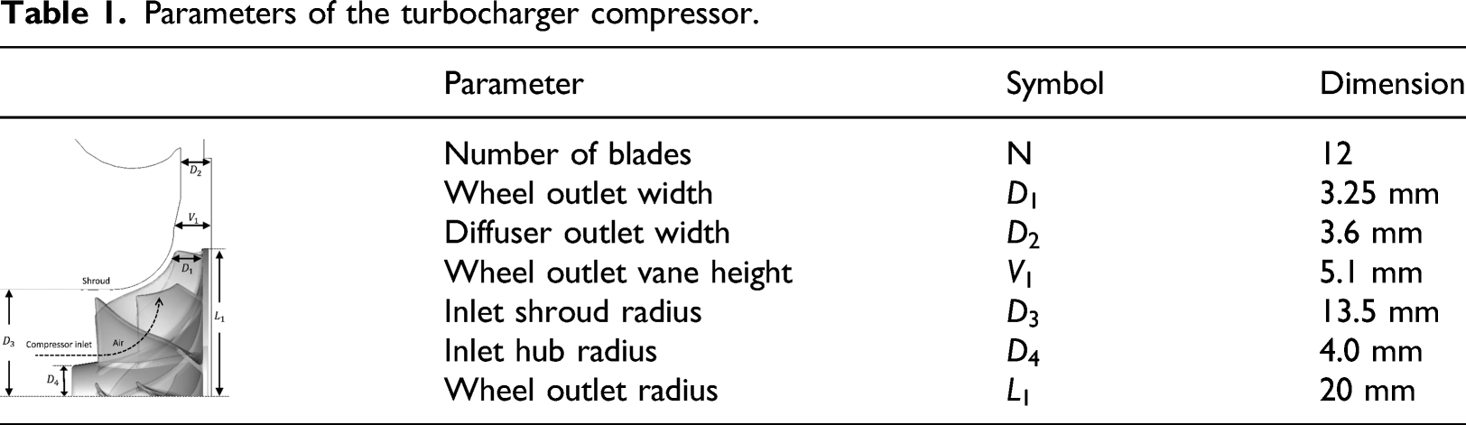
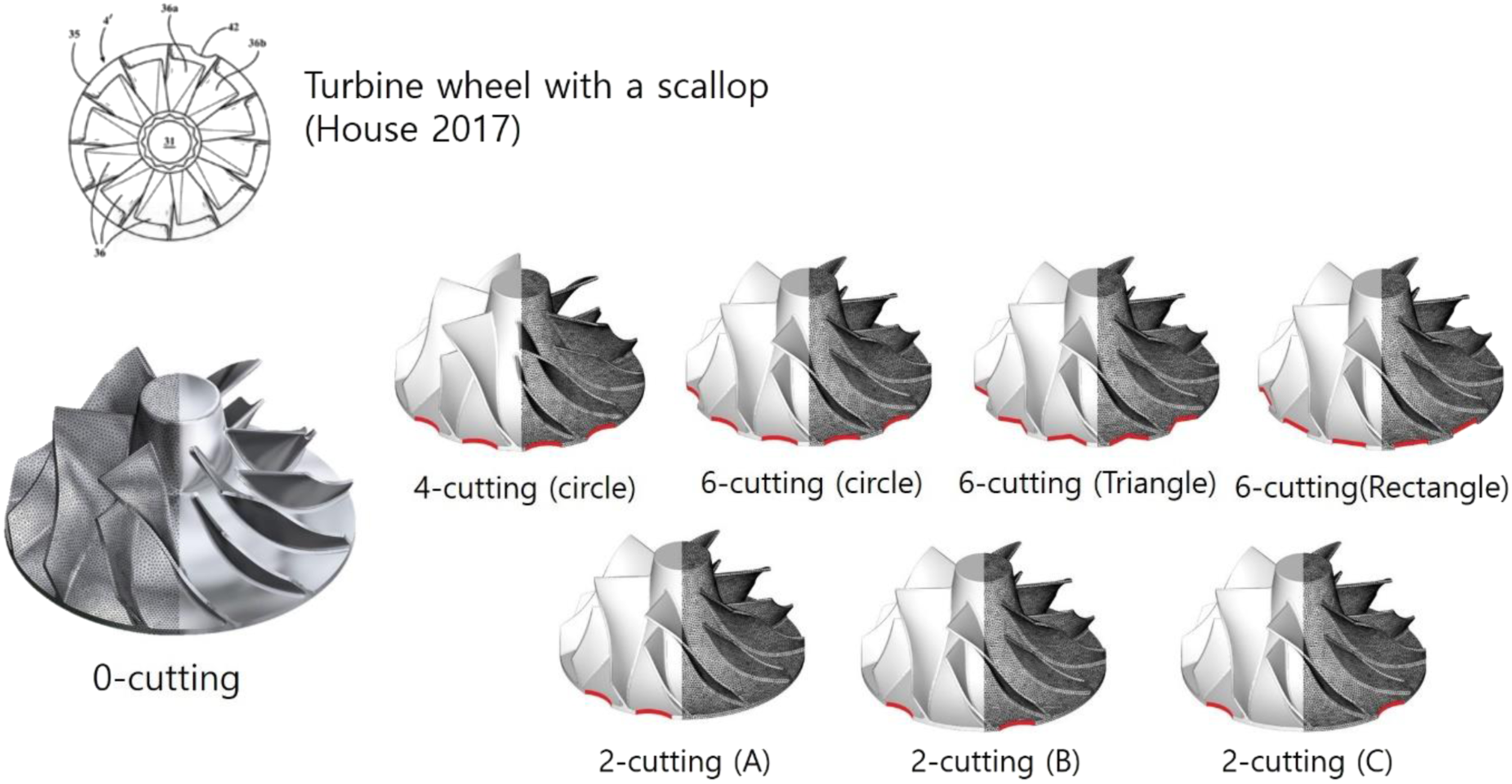
a turbocharger compressor for a small diesel engine with a displacement volume of 0.0016 m3 as the basic geometry was selected. As shown in Figure 1, it consists of a compressor wheel, volute, inlet duct, and outlet duct. The compressor wheel contains six main and six splitter blades; the geometrical details are listed in Table 1. To achieve rotational balance, the shape of the compressor wheel can be changed by cutting it in various ways. Figure 2 shows the locations and types of cuttings applied to the compressor wheel. In this study, three types of cuttings were chosen: circular, rectangular, and triangular. In each case, the same volume is removed. To compare the shape change according to the times of cutting, the number of circular cuttings is changed by 0, 2, 4, and 6. Computational domain and boundary conditions of a turbocharger compressor. Parameters of the turbocharger compressor. Grid points of wheel blade and cutting type.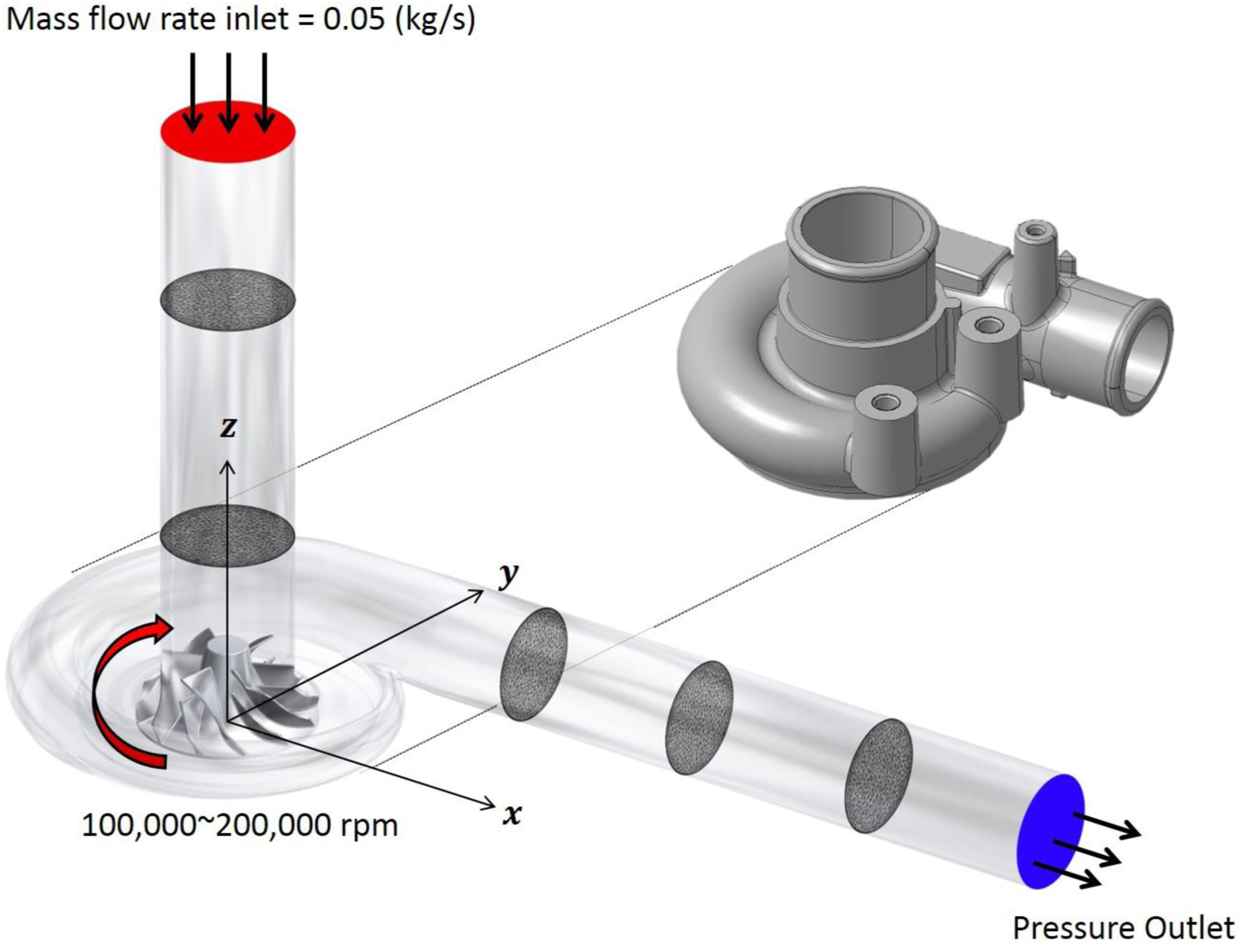
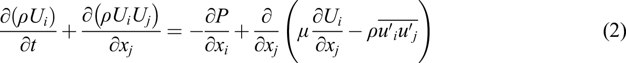
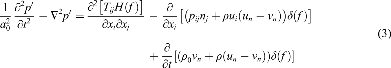
For compressible turbulent flows, the Reynolds-averaged Navier–Stokes (RANS) model and a detached-eddy simulation (DES) based on the shear-stress-transport (SST) k-ω model were employed. The governing equations of continuity and momentum are as follows
To examine the flow-noise characteristics due to different wheel shapes, a constant mass-flow rate of 0.05 kg/s at the inlet and constant pressure at the outlet was adopted. At the inlet, air flow at the standard conditions of 101,325 Pa and 300 K is assumed. A turbulent intensity of 2% and a turbulent viscosity ratio of 100 is also imposed. The density, viscosity, and specific heat capacity are based on the ideal-gas equation of state, the Sutherland law, and kinetic theory, respectively. The rotation speed of the compressor wheel is fixed at 160,000 r/min. The governing equations are solved using the pressure-based coupled algorithm of ANSYS Fluent. 16 A bounded central-differencing scheme is used for the convection terms, and a second-order implicit scheme is selected for temporal integrations. The convergence criterion is that the residuals are less than 10−6. For the time integration, the time step size of 3.75 × 10⁻⁷ sec is adopted. It corresponds to the 1/1000 rotation of wheel at the rotation speed of 160,000 r/min. For time statistics and the Fast Fourier Transform, flow variables are sampled during 40 rotations of the compressor wheel. Then, the frequency resolution is fshaft/1000, where the shaft frequency of the rotating wheel is given by fshaft = Ω/60. Here Ω is the rotation speed in revolutions per minute (rpm).
Validation and noise parameters
To find a proper grid resolution, the grid dependency for six cases with 5×10⁵–1.05×10⁷ tetrahedral mesh points was tested. To maintain y+ ∼ 1, the blade surfaces are represented by 10 prismatic layers. The pressure ratio for each different grid as a representative variable for the turbocharger compressor was used. The pressure ratio is defined as the ratio of the outlet total pressure Pout to the inlet total pressure Pin. As can be seen in Figure 3, the pressure ratio converges to a constant value for grids with more than 2 × 10⁶ mesh points. Approximately 5 × 10⁶ tetrahedral mesh points for all the selected compressors were finally adopted. Pressure ratios for different-sized grids.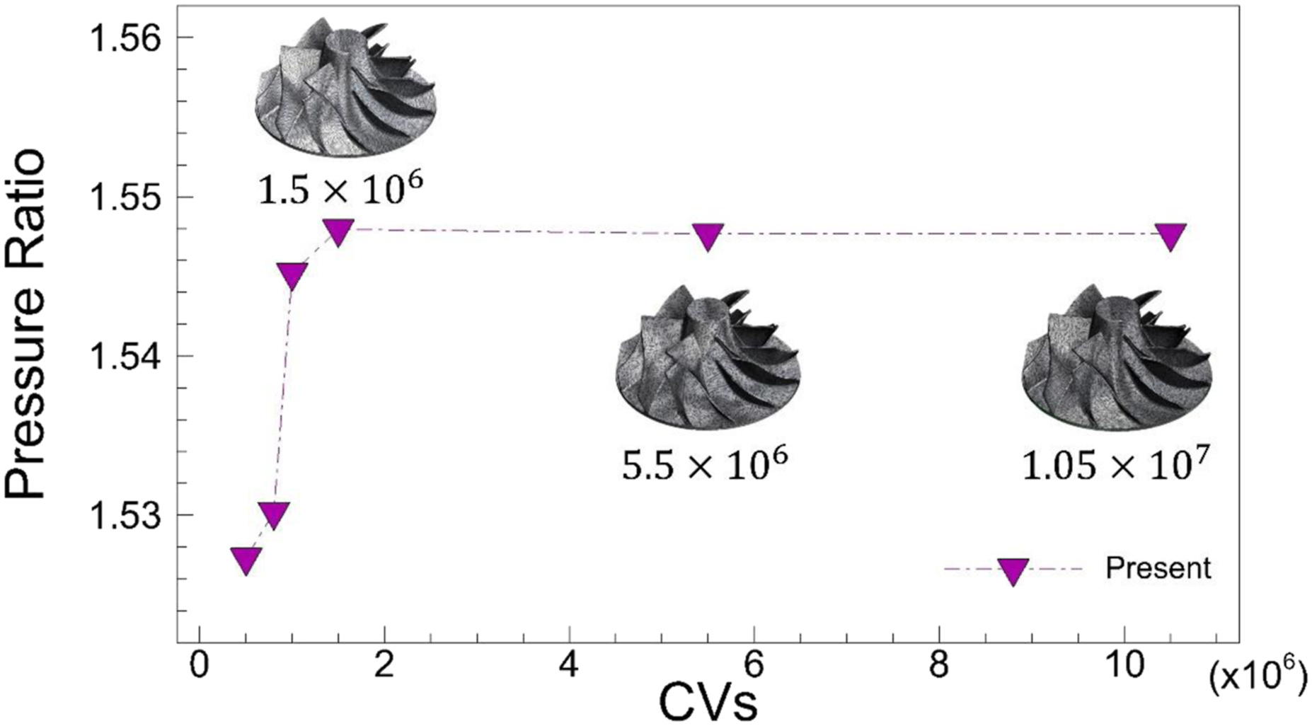
Since there was no data for the present turbocharger, the numerical validity is performed for two similar turbochargers. In Figure 4, the pressure ratios are presented with the results of Song et al.
17
for 120,000–220,000 r/min and 0.064–0.096 kg/s. The turbocharger performance map is compared to the experiment of Bontempo et al.
18
Here, the pressure ratio is obtained by Pout/Pin of the inlet and outlet total pressures. Although the geometrical details of the number of blades and wheel diameter are different, two studies17,18 are selected because their applications are designed for small engine applications similar to the present 1.6-L engine. To compare the other results in similar conditions, the pressure gradient and the mass flow rate are normalized by the values at 160,000 r/min and 0.078 kg/sec. This mass flow rate is the maximum value for 160,000 r/min in Bontempo et al.
18
The present results are very similar to the experimental data of Song et al.
17
as the rotation speed increases. However, the present value slightly overpredicts the pressure rise at higher rpms because of the geometrical differences between the volutes and inlet and outlet ducts in the two studies. Also, due to the different configuration, the present compressor map shows some discrepancy with the experiment of Bontempo et al.
18
Although there is room for accuracy to be improved by other methods, the present compressor map follows the general trend of the dependence on the mass flow rate and the wheel rotation. Comparison of streamlines, pressure ratio, and compressor map.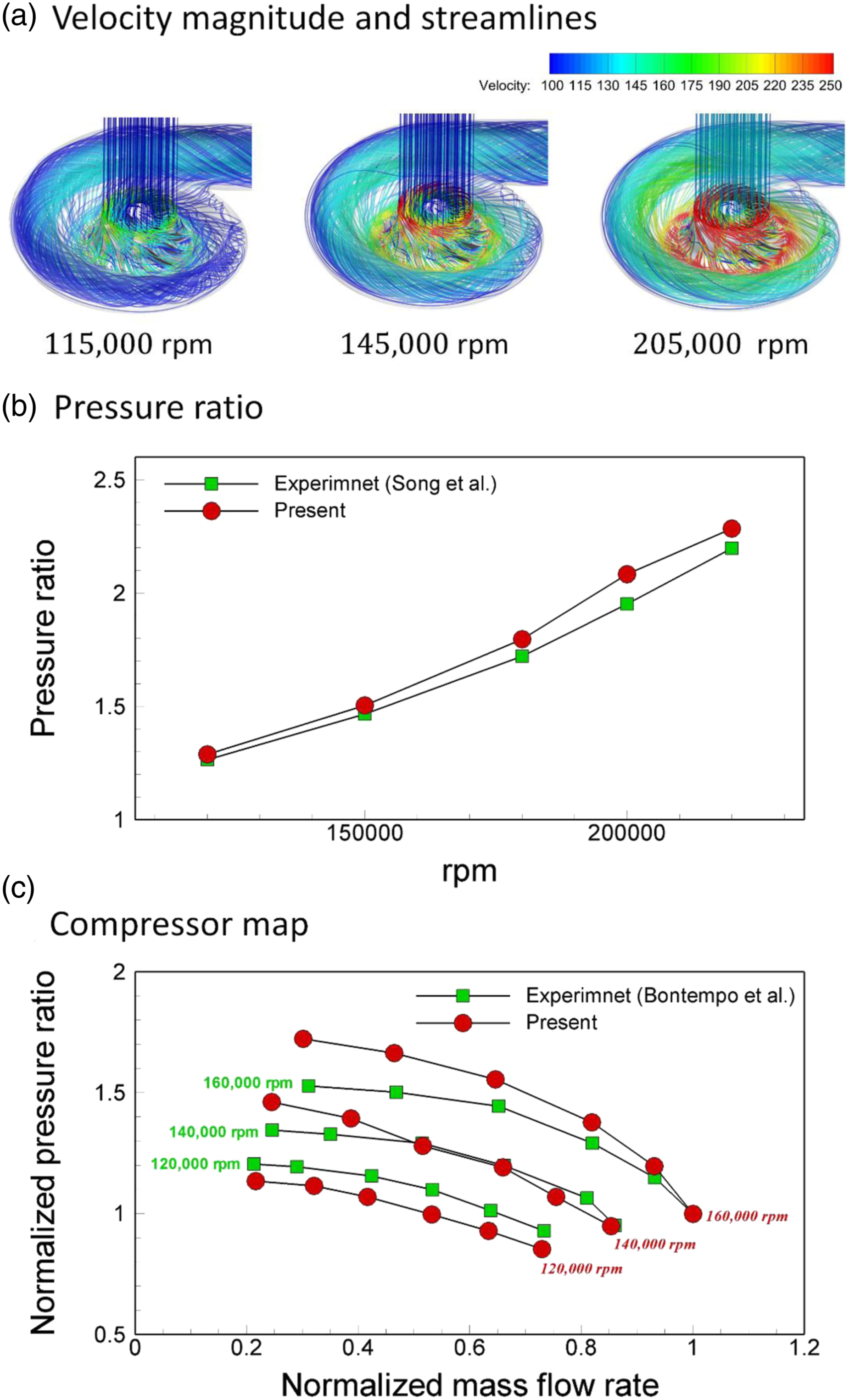
A broadband noise-source model is appropriate for situations in which the noise is continuously distributed across a broad frequency range without distinctive tones. The strengths of the noise sources can be evaluated for turbulent flows as follows. The surface acoustic power (SAP, W/m2) due to the fluctuating pressure is given by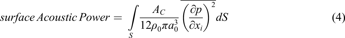


Results and discussion
Rotational balance according to the cutting process
Due to machining tolerances, one is generally faced with the problem of balancing compressor wheels. In this study, this problem is analyzed from the viewpoint of fluid forces using CFD. From our literature survey, this process has never been attempted before. In real-world situations, an unbalanced wheel is balanced by cutting it.8,15 Under such circumstances, the fluid forces act to help restore rotational balance in addition to the effect of mass redistribution. The shape modification resulting from the elimination of the unbalanced mass also plays a role in restoring the eccentricity of the rotation axis due to the difference in mass distribution. For the computational domain of Figure 1, the fluid forces of the compressor wheel are evaluated at the rotation speed of 160,000 r/min and the mass flow rate of 0.05 kg/s. As shown in Figure 5, the instantaneous forces due to the unsteady pressures and stresses exhibit azimuthally wavelike traces. They are not eccentric but are instead nearly concentric. The wavy behaviors are mainly understood because the turbulent flows develop periodically on blade passages of the compressor wheel. The force components Fx and Fy are approximately 1/200 the size of Fz. Considering the balance of the rotating shaft, it is desirable for the resultant of the forces Fx and Fy to change along a concentric circle. However, if Fx or Fy are greater than the inertial force and are unbalanced, the rotation axis can be moved in the x–y plane. Time histories of forces acting on the compressor wheel.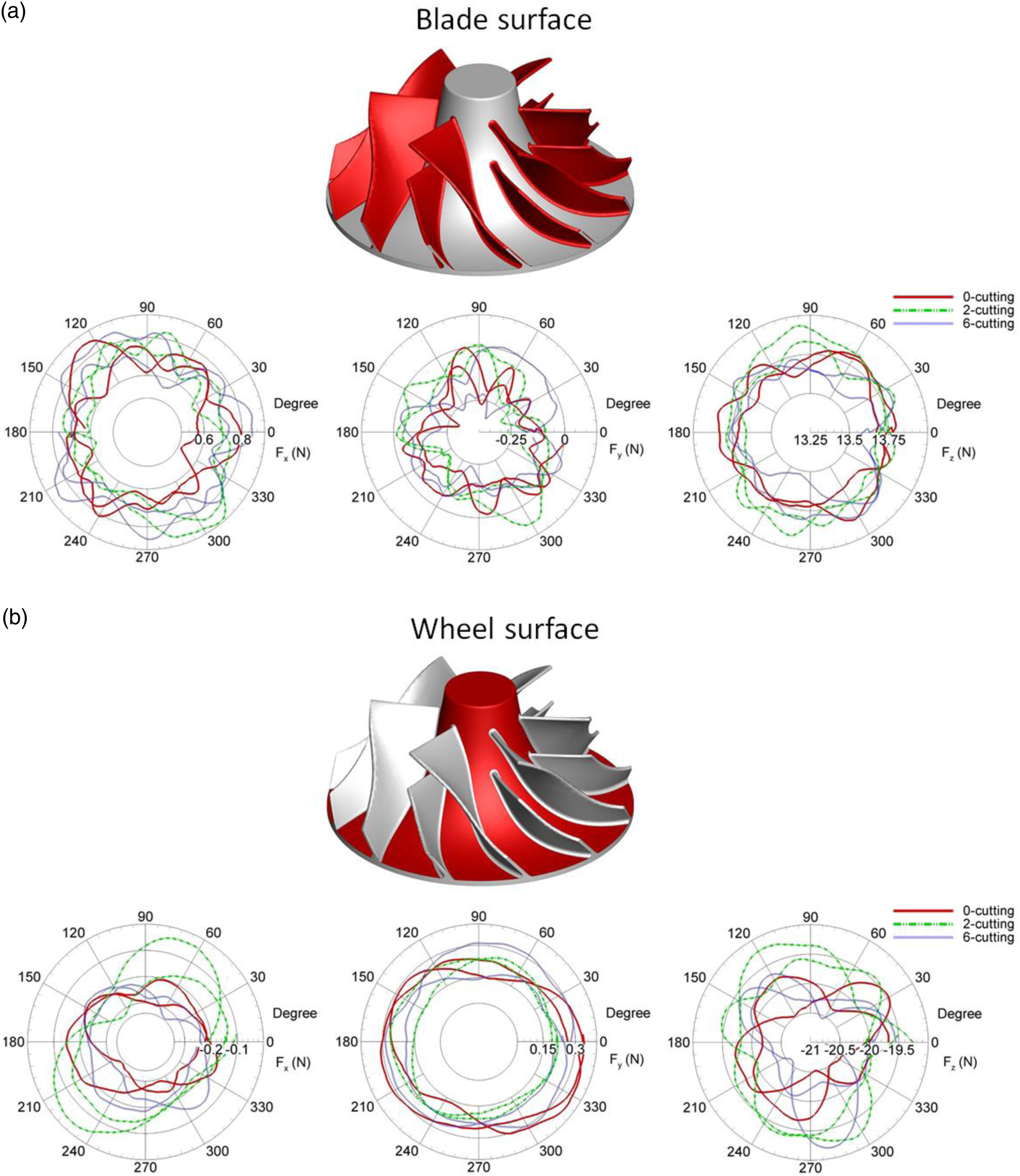
Based on this, numerical verification of balance cuttings from the baseline geometry of a balanced state was started. For the compressor wheel, if the resulting fluid forces are unbalanced, it can be understood that the wheel rotation is tilted. The resulting eccentricity is dependent on the magnitude of the fluid forces. Accordingly, if the balance cuttings have the effect of tilting the rotation axis, the fluid forces act to help restore the rotation axis to a balanced state. Using the relationship between wheel shape and fluid forces, the tilting of the rotation axis of the modified compressor wheel was examined. The results contribute to establishing the numerical verification of the cutting process. After performing a basic simulation for the rotation axis (ex, ey, ez)original = (0, 0, 1) of the modified compressor, the tilt angle based on the fluid forces was calculated. Here ex, ey, and ez are the components of a unit vector. Then, a new simulation for the tilted rotation axis based on the angle opposite to (ex, ey, ez)calculated in the x–y plane, where
The dependence on the number of cutting parts of the predicted unit vector and line of action of the resultant force on the compressor wheel was investigated. Figure 6 shows the unit vectors for the rotation axis (ex, ey, ez) = (0, 0, 1). As the number of the cutting parts increases, the magnitudes of the components of the unit vectors decrease. That is, the angle between the fluid-force vector and z-axis increases. For the 6-cutting case, the predicted unit vector of the fluid force is (ex, ey, ez) = (−0.00870, −0.00359, 0.99975) and the coordinate-direction angles are (α, β, γ) = (90.4985°, 90.2057°, 1.2812°). This represents the restoration effect on the unbalanced rotation produced by the cutting process. The rotation axis (ex, ey, ez) = (0, 0, 1) is then replaced by (ex, ey, ez) = (0.00870, 0.00359, 0.99975). The new direction of the fluid forces then becomes (ex, ey, ez) = (0.00071, 0.00059, 0.99992), and the coordinate-direction angles are (α, β, γ) = (89.9593°, 89.9662°, 0.7247°). Considering only the fluid forces due to the compressor-wheel shape, the eccentricity of the rotation axis is improved by approximately 50%. Similar effects are confirmed for the 2- and 4-cutting cases; that is, the fluid forces act to restore the balance state. Therefore, balance cuttings have the side effect that the shape change acts to help restore rotation balance. Components of the unit vectors and coordinate-direction angles between the resultant fluid force and z-axis depending on the number of cuttings.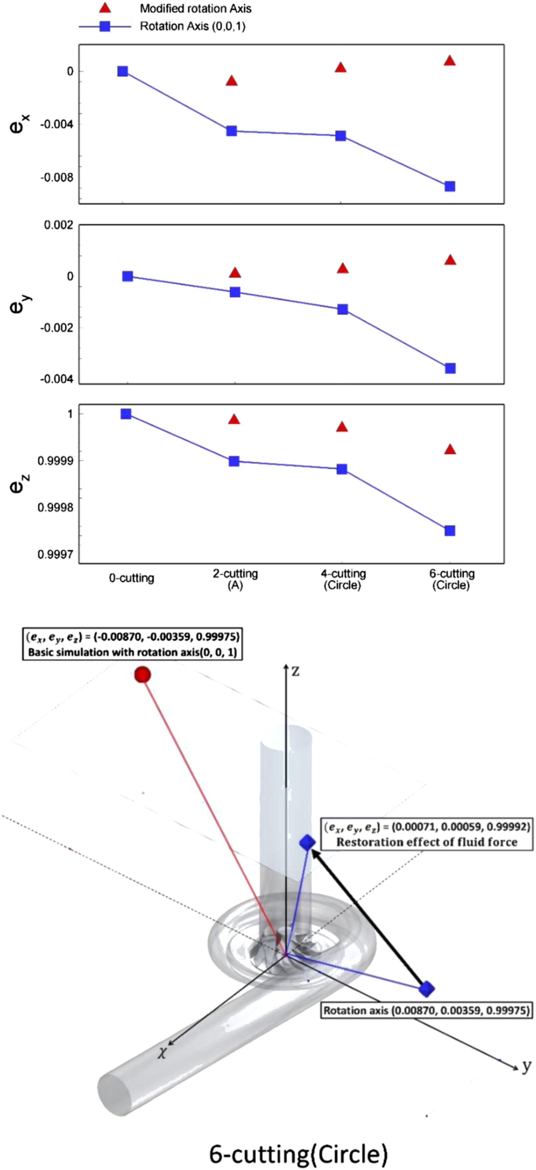
Flow characteristics
Streamlines with the magnitude of the velocity indicated, the compressor performance of pressure and flow coefficients for different wheel shapes are shown in Figure 7. The pressure coefficient is defined as ψ = (Pout–Pin)/(ρΩ2D2), and the flow coefficient is defined as ϕ = Q/(ΩD3), where Ω, ρ, Q, and D are the rotational speed, density, flow rate, and wheel diameter, respectively. In a turbocharger compressor, the kinetic energy due to wheel rotation is converted to pressure energy through the volute. It is very important for the compressor wheel to increase the kinetic energy of the fluid as much as possible. Moreover, the volute configuration should have the characteristic that it can convert kinetic energy into pressure energy. For the present turbocharger, the Mach numbers for the 0-cutting case are predicted to be 0.268 for the inlet, 0.368 for the compressor-wheel inlet, 0.993 for the volute inlet, and 0.283 for the outlet. This means that the high-speed rotation of the compressor wheel is generating a strong compressible flow. In general, due to friction and compressibility losses, the pressure coefficient has lower values than the theoretical relation of pressure and flow rate. This general behavior of the performance curve is observed for all compressor wheels. Although the compressor wheel is modified by the cutting process, this result means that the difference between the overall flow structures for all cases is negligible and that the cutting effects have no significant impact on the performance of the turbocharger. It is, therefore, reasonable that the cutting effects on the flow variation and noise are limited to the blade tip and interspace between the wheel and volute. Comparison of streamlines and compressor performance for different wheel types.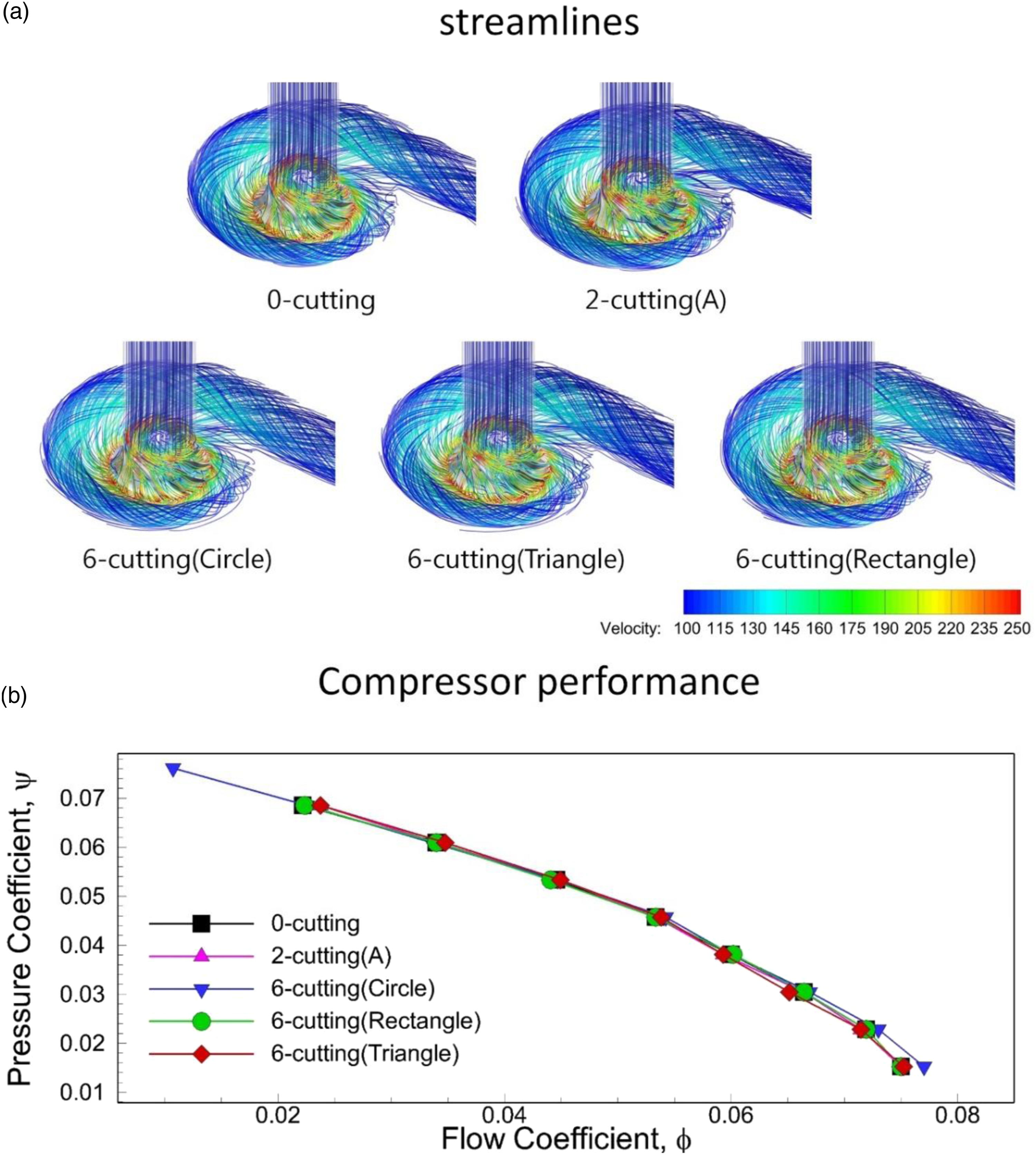
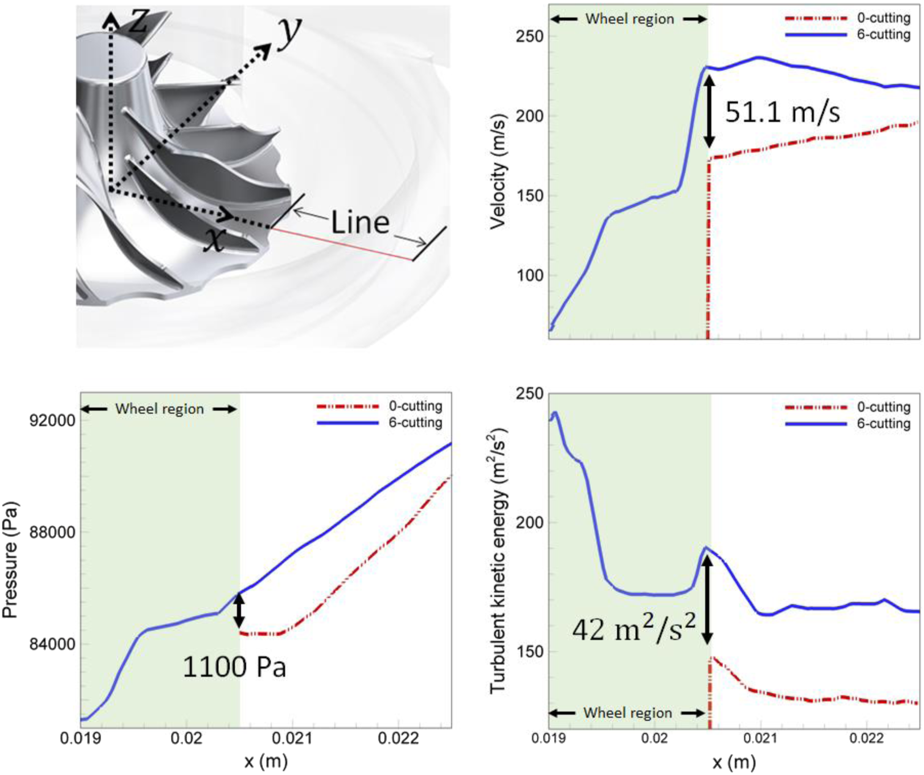
To see the cutting effects on the flow fields, the variations of the magnitude of the velocity, pressure, and turbulent kinetic energy in the space between the compressor wheel and volute were examined. At the same rotational condition, the instantaneous distributions of these quantities for several modified compressor wheels are shown in Figure 8. Compared with the 0-cutting case, the velocity magnitude in the front of the passage between the blades that contain the cutting parts is significantly increased. As the number of cutting parts increases, the high-velocity region is enlarged. The high velocities near the cutting parts of the wheels produce enhanced strain rates. In general, the production of turbulent kinetic energy increases in proportion to μ
e
S
ij
S
ij
, where μ
e
is the eddy viscosity and S
ij
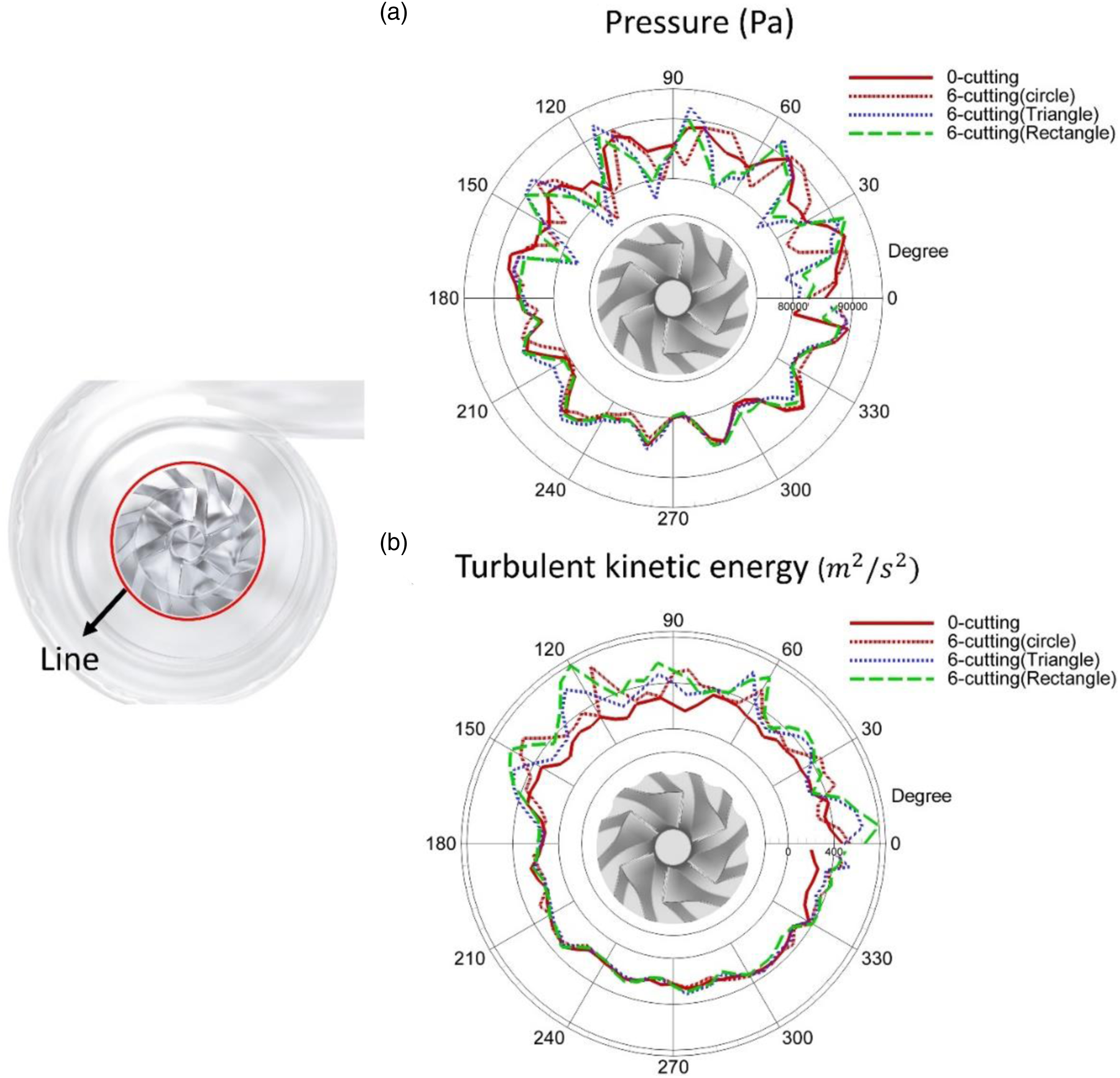
is the strain rate. This confirms that the turbulent kinetic energy near the cutting region is increased by the highly strained structures. To examine specific differences, the red line between the wheel and volute shown in Figure 9 was selected. The distributions of the turbulent kinetic energy, pressure, and velocity along that line for two cases were obtained: a 0- and 6-cutting case with circularly shaped cuttings. Unlike the 0-cutting case, the flows develop for the 6-cutting case in the cutted part of the wheel region. Near the wheel outlet, the 6-cutting case has large values of all three measured quantities. However, the change in the values from the wheel outlet to the end of the red line is similar for the two cases. It is natural to expect the cutting effects to be concentrated on the wheel outlet between a pair of adjacent blades. Since this change in the flow affects the characteristics of the inflow to the volute and the development of the flow between the blades and the shroud, it needs to be examined in detail. The distributions of pressure and turbulent kinetic energy around a circle concentric with the wheel axis near the outlet at the circumference of the wheel are shown in Figure 10. Compared to the 0-cutting case, the modified compressor wheel induces wavelike variations of the pressure and turbulent kinetic energy. The peak-to-peak variations are enhanced near the cut regions of the compressor wheel. Differences that depend on the cutting shape are not severe, although the rectangular shape produces slightly more exaggerated wavelike features. From these flow structures, it is expected that the flow fluctuations due to the increased turbulent kinetic energy are the main source of noise in the present turbocharger compressor. Hence, the interaction between the turbulent flows near the wheel outlet and the volute needs to be considered as important. Instantaneous velocity magnitude, pressure fluctuation, and turbulent kinetic energy between wheel and volute. Pressure, and velocity, and turbulent kinetic energy distributions along a line. Pressure and turbulent kinetic energy distributions around a circle concentric with the axis near the wheel outlet.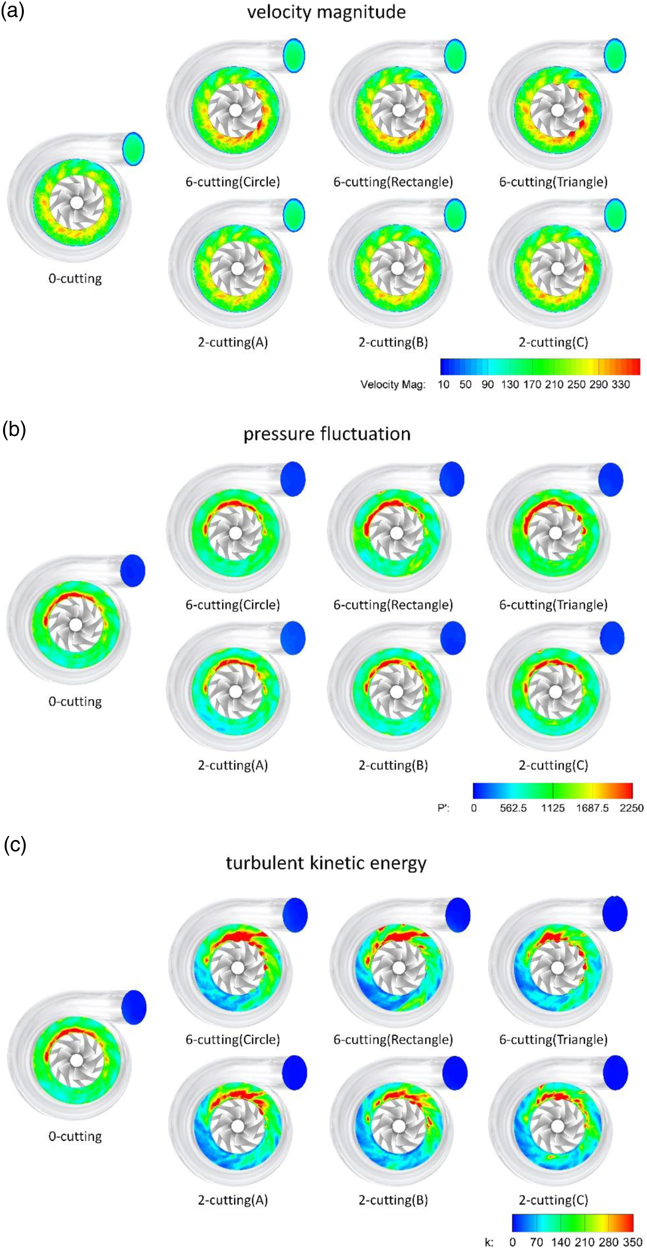
To explore the unsteady characteristics, the time histories and Fourier spectra of the pressure and turbulent kinetic energy at four monitoring points (labeled M1–M4 in Figure 11) were obtained. These points were selected to be in the volute near the cut region of the compressor wheel in order to see the geometrical effects. After passing through the transition period, the flow field is monitored at every time step. The Fourier transform is performed for 40,000 samples of pressure and turbulent kinetic energy. In Figure 11, the pulsation feature of the shaft frequency is not clearly seen in either the 0- or 6-cutting cases. As the position of the monitoring point moves away from the wheel blade (M1→M4), the amplitudes of the high-frequency components are reduced. The present compressor has fBPF = 16,000 Hz and fshaft = 2667 Hz, because the wheel rotates at 160,000 r/min and has six main blades. In the pressure spectral densities at position M1, the primary frequencies for both the 0-cutting and 6-cutting cases are all near fBPF. However, it is interesting that a narrow band at 3828 Hz is observed at M1 in the pressure spectrum of the 6-cutting case. An enhanced density at 3000 Hz at M1 is also obtained for the spectrum of the turbulent kinetic energy in the 6-cutting case. The frequencies near 3000 Hz are related to the unsteady behaviors of secondary flows.19,20 Therefore, the compressor wheel modified by cutting is expected to have a feature close to the source of the “whoosh” noise. Time history and Fourier spectra of pressure and turbulent kinetic energy at monitoring points.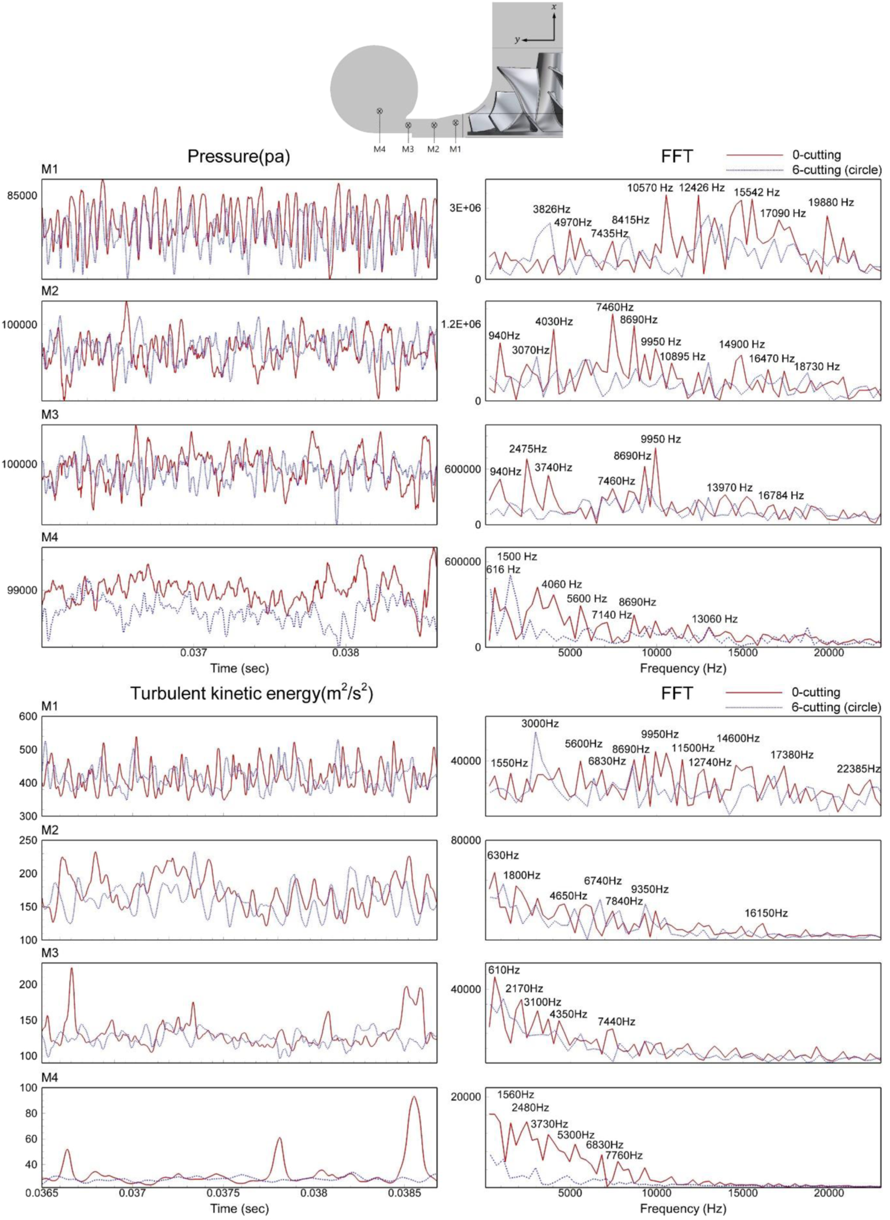
Noise characteristics due to the cutting type
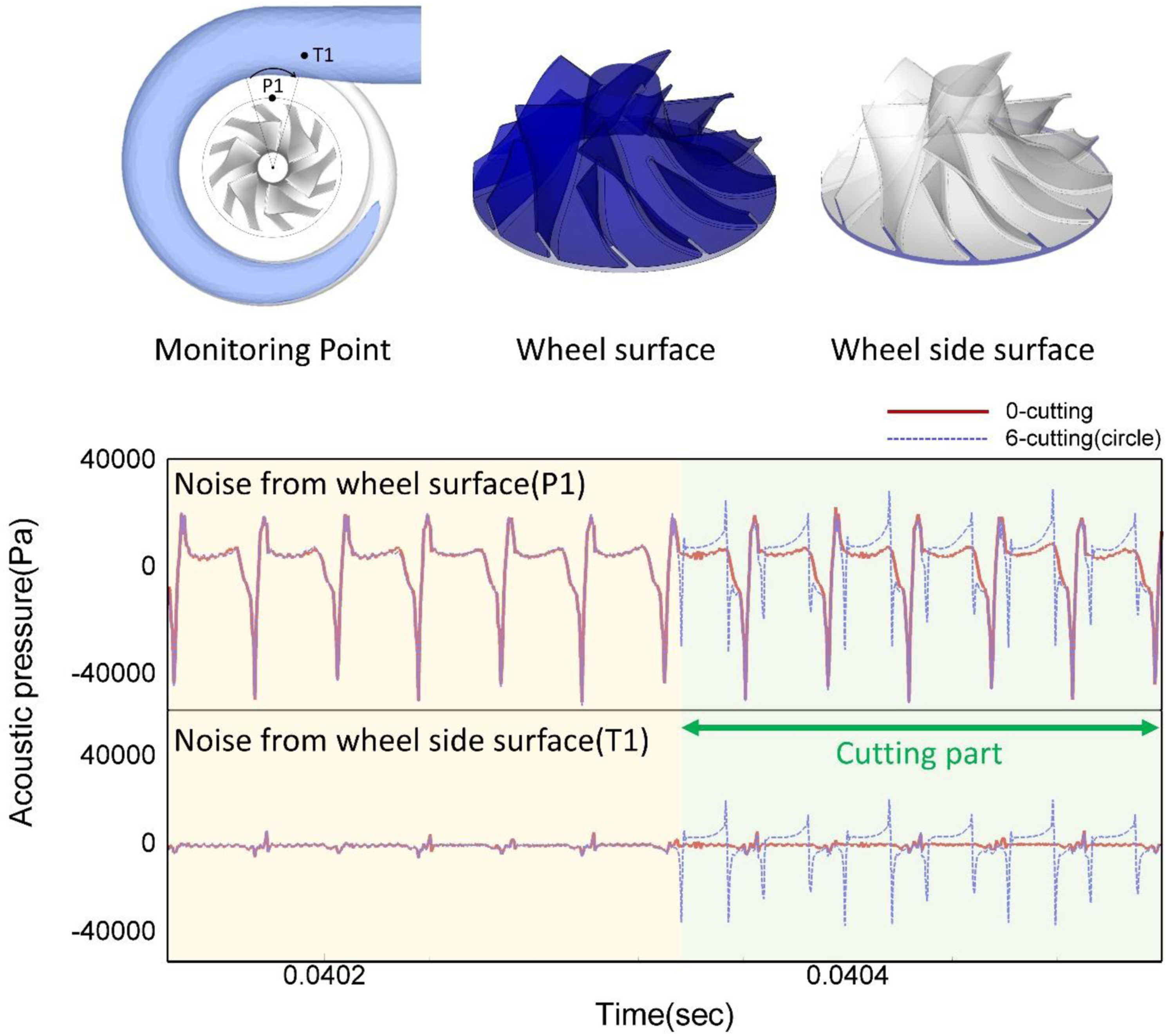
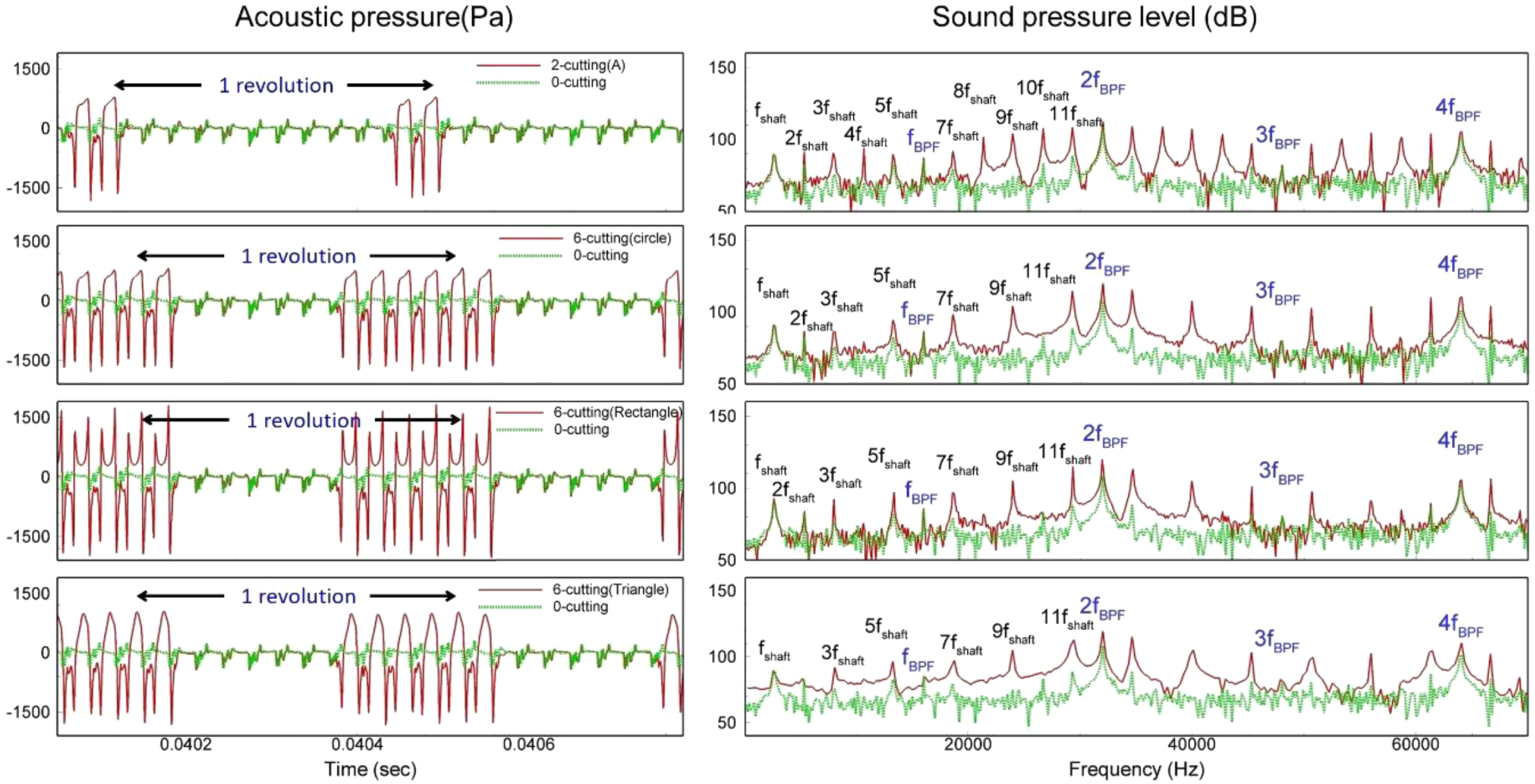
To examine the noise characteristics of the compressor wheel, the wheel and side surface of the wheel that contacts the volute as the noise-generating surfaces were chosen to be studied because it is the wheel surface that is changed by the cutting process. First, the receiver point was placed at the wheel inlet, as shown in Figure 12. After the turbulent flow is fully developed, the acoustic pressure is obtained for 40 rotations of the compressor wheel. For 0.015 s, the acoustic pressure is stored at the sampling rate of 2667 kHz. At this position, the pressure fluctuation is only affected by the main blades. As a result, fBPF is the fundamental frequency for the acoustic pressure, and its harmonics can be observed from the noise source at the wheel surface. In the Fourier spectrum shown in this figure, fshaft, fBPF, and 2fBPF are dominant. However, as shown in the lower panels in this figure, the SPL due to the side surface of the wheel has no fundamental frequency except for fshaft. For one revolution of 3.75x10⁻⁴ sec at 160,000 r/min, measurements of the acoustic pressure at monitoring points near the compressor wheel and tongue are shown in Figure 13. As can be seen, two surfaces of the compressor wheel is selected to check the cutting effects. The wheel surface means the wall surface of the flow passage and the blades. The wheel side represents the side wall surface of wheel outlet. In Figure 13, when the receiver is located at P1, the variation of the acoustic pressure is presented for the noise source of wheel surface. Also, the acoustic pressure at the tongue (T1) is obtained for the noise source of wheel side. The two representative 0- and 6-cutting (circle) cases are compared for one revolution. The compressor wheel has 12 interspaces between the main blades and the splitter blades. Six blade interspaces were, therefore, modified for the 6-cutting case. The time history shown in Figure 13 for one revolution is divided into such regions. The 12 periodic patterns clearly show the characteristics of the BPF. At point P1, the wheel-surface noise does not change greatly when the cutting parts pass; however, the peak-to-peak amplitudes of the 6-cutting case decrease when the cutting parts pass the receiver. In contrast, the wheel-side noise of the 6-cutting case measured at T1 changes greatly when the cutting parts pass. Since the cutting is done between adjacent blades, it can be concluded that the change in the turbulent flow is concentrated on the side surface of the wheel rather than on the blade surfaces. Acoustic pressure history at a monitoring point of the wheel inlet. Acoustic pressure at the monitoring points P1 and T1 for the 0- and 6-cutting (circle) wheels during one revolution.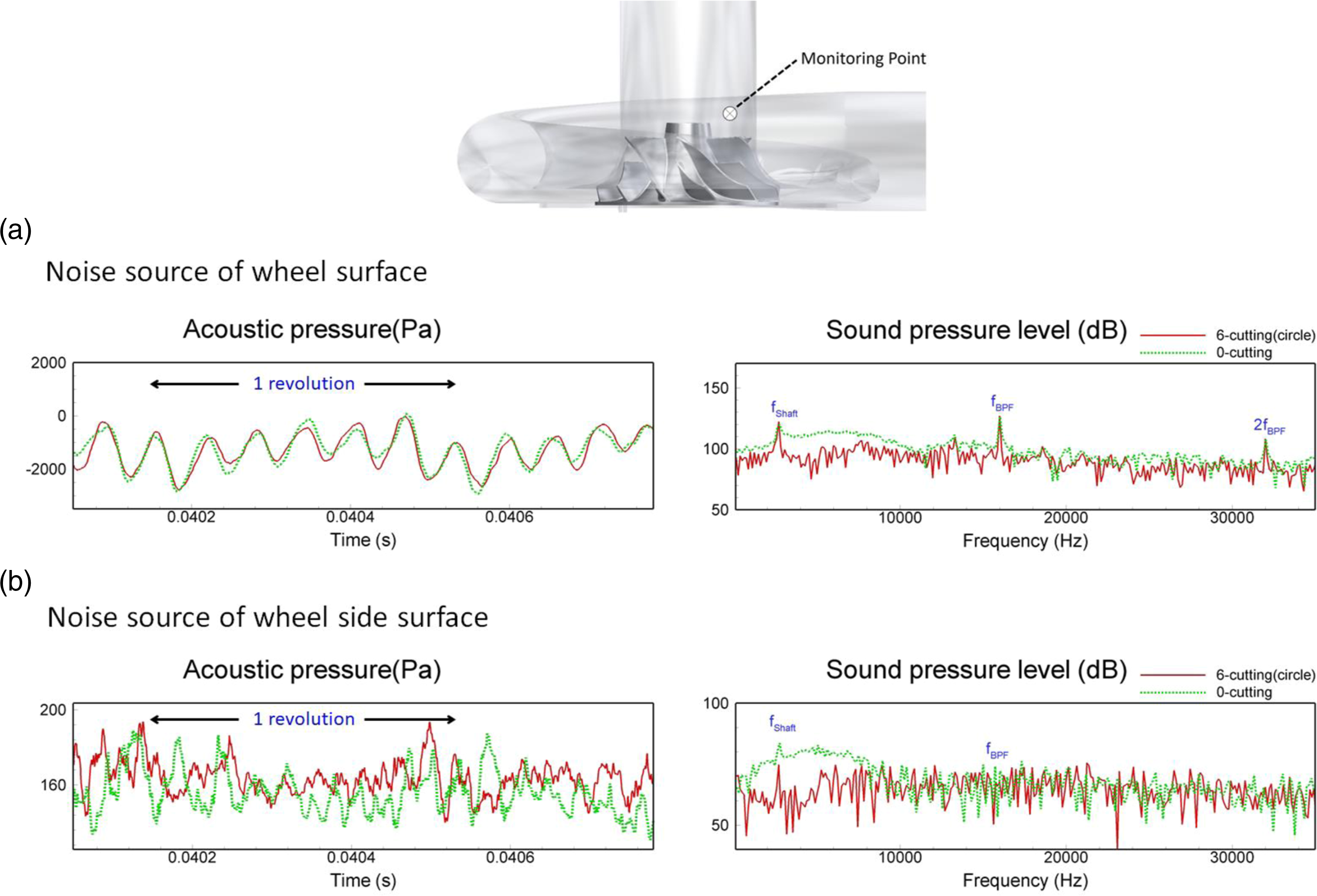
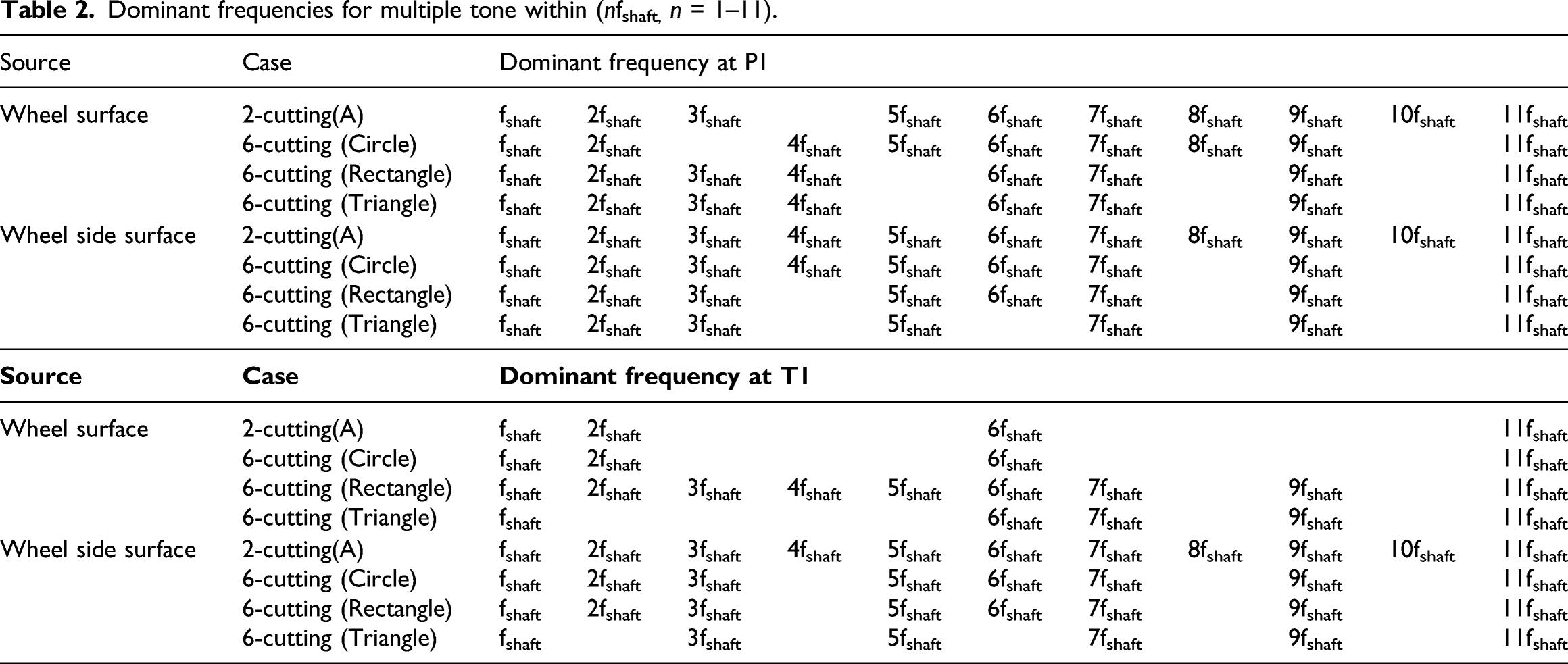
The acoustic pressure and the SPL at P1 near the compressor wheel for the two noise sources at the wheel and side surface of the wheel are shown in Figure 14 and 15. In order to get the Fast Fourier Transform, after the transient flows, the acoustic pressure is sampled for 40,000 time steps. In general, pressure pulsations are generated at discrete frequencies proportional to the shaft frequency and the number of blades. For all cases, peak levels are observed at 2fBPF and 4fBPF, which are harmonics of fBPF, because the acoustic pressure is affected by both the main and the splitter blades. The high amplitude at the BPF is a consequence of the small distance between the compressor wheel and the volute tongue. Depending on the number of passing of blade interspaces, fshaft and its harmonics (nfshaft) are observed in the interfrequency band between the dominant frequencies of 2fBPF and 4fBPF. The noises are classified by several frequencies nfshaft near fBPF and its harmonics. For the 0-cutting case, the acoustic pressure caused by the side surface of the wheel is much weaker than that caused by the wheel surface. This is because the turbulent flows in the passages between the 12 blades are very similar. However, when cuttings are introduced, the flows changed by the cutting parts affect the process by which the kinetic energy is transformed into pressure energy. For the 2-cutting(A) case in Figures 14 and 15, it is clear that the dominant frequencies are proportional to the rate fshaft at which the blade passes. That is, multiple harmonics of fshaft (nfshaft, n = 1–11) appear distinctly. This feature is more clearly observed for the noise source at the side wall surface of wheel outlet. As shown in Figure 15, for the 6-cutting (circle) case, the dominant frequencies are fshaft, 2fshaft, 3fshaft, 4fshaft, 5fshaft, 6fshaft, 7fshaft, 9fshaft, and 11fshaft, while the amplitudes at the frequencies 8fshaft and 10fshaft are significantly reduced. Comparing the 6-cutting (triangle) case to the 6-cutting (circle) case, it is interesting that the peaks at the frequencies 4fshaft and 6fshaft are additionally weakened. From Han et al.,
21
noises that contain multiple tones at harmonics of the shaft frequency are called “multiple-pure-tone” (MPT) noise or “buzz-saw” noise. Therefore, the above results show that the noises caused by the cut parts of the wheel have the features of buzz-saw noise. Acoustic and sound pressure levels at P1 caused by the wheel surface (see the surface definition in Fig. 13). Acoustic and sound pressure levels at P1 caused by the side surface of the wheel (see the surface definition in Fig. 13).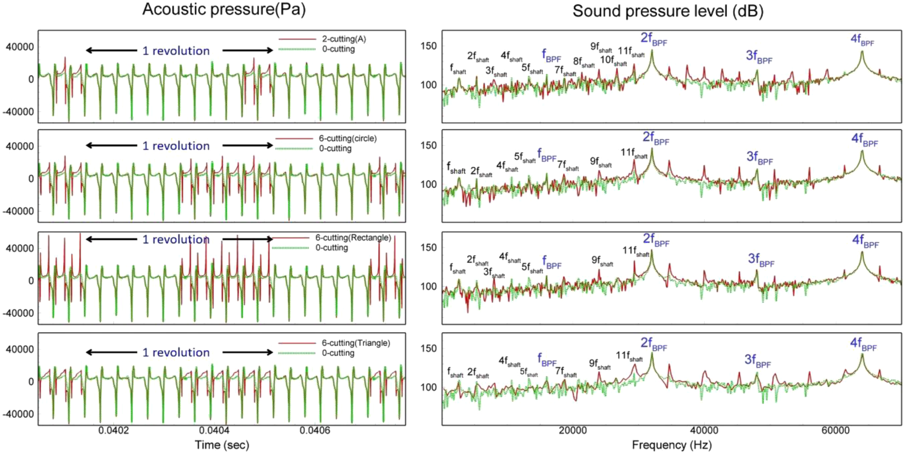
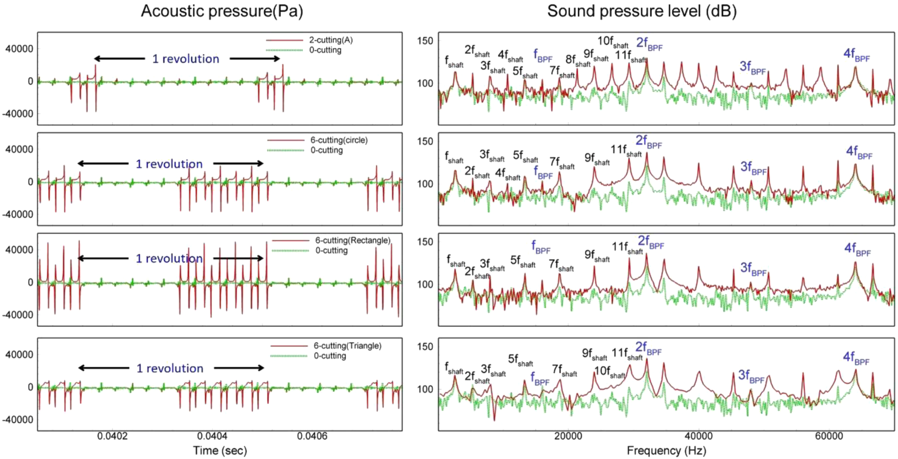
Figure 16 and 17 show the variations of the acoustic pressure and the SPL at point T1 of the tongue. Similar to the sound-pressure changes at P1, the multiple harmonic feature at T1 is clearly seen for the noise source of the wheel side surface. In Figure 17, for the 2-cutting(A) case, the SPL at T1 is very similar to that at P1, and the pattern of multiple tones at the frequencies nfshaft (n = 1–11) is very clear. However, the difference in the SPLs between the 2-cutting and the 0-cutting cases is slightly greater than the difference observed in Figure 15. The noise from the wheel surface is almost unaffected by the 6-cutting type, but the noise from the side surface of the wheel is clearly affected by it. This is very similar to the results observed at P1. For the 6-cutting (triangle) case in Figure 17, the noise from the wheel surface has the dominant frequencies fshaft, 6fshaft, 7fshaft, 9fshaft, and 11fshaft, while the frequencies fshaft, 3fshaft, 5fshaft, 7fshaft, 9fshaft, and 11fshaft are dominant in the noise from the side surface of the wheel. The characteristic of weakening amplitudes at 4fshaft, 6fshaft, 8fshaft, and 10fshaft is similar to the pattern observed at P1 of Figure 15. The dominant frequencies of the acoustic pressure at P1 and T1 are summarized in Table 2. It can be concluded that the acoustic pressures for the modified compressor wheels are similar to the acoustic pressure characteristics of compressor wheels with reduced numbers of blades. Also, the peak-to-peak difference of the acoustic pressure increases for the compressor wheels with the cutting parts and it is the largest for the 6-cutting (rectangle) case. As shown in Figures 15 and 17, these changes are reflected in the SPL variation. The sound levels at the dominant frequencies of the modified compressor wheels are more enhanced than those of the 0-cutting case. From these features, it can be concluded that unlike the 0-cutting case, the buzz-saw noise is reinforced for a compressor wheel modified by cutting. It can also be concluded that when the balance cuttings are inevitably introduced, the rectangular cutting shape is most disadvantageous for noise reduction. Acoustic and sound pressure levels at T1 caused by the wheel surface (see the surface definition in Fig. 13). Acoustic and sound pressure levels at T1 caused by the side surface of the wheel (see the surface definition in Fig. 13). Dominant frequencies for multiple tone within (nfshaft, n = 1–11).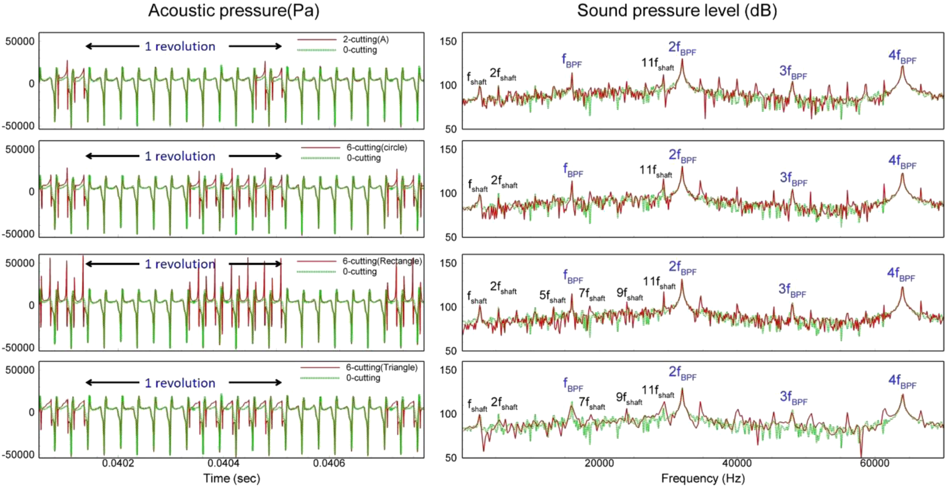
In general, the flow noises in a turbocharger compressor are affected by the fluctuating flow fields. The pressure differences between the pressure and suction side of the different wheels are shown in Figure 18. To see the difference according to the cutting type, the pressure side of main blade and the suction side of splitter blade are selected for a passage with the cutting part. As the number of circular cutting parts is increased, this pressure difference also increases. The largest values are obtained for the rectangular and triangular 6-cutting types. From Raitor and Neise,
20
if the pressure difference between the pressure side and the suction side of a wheel blade is sufficiently high, tip-clearance noise (TCN) is generated. As shown in Figures 14 to 17, the sound-pressure levels for the modified wheels become stronger at frequencies slightly larger than fBPF. Therefore, the buzz-saw noise from a modified compressor wheel generates TCN with slightly higher tones. Pressure difference between pressure and suction side of the wheel blade.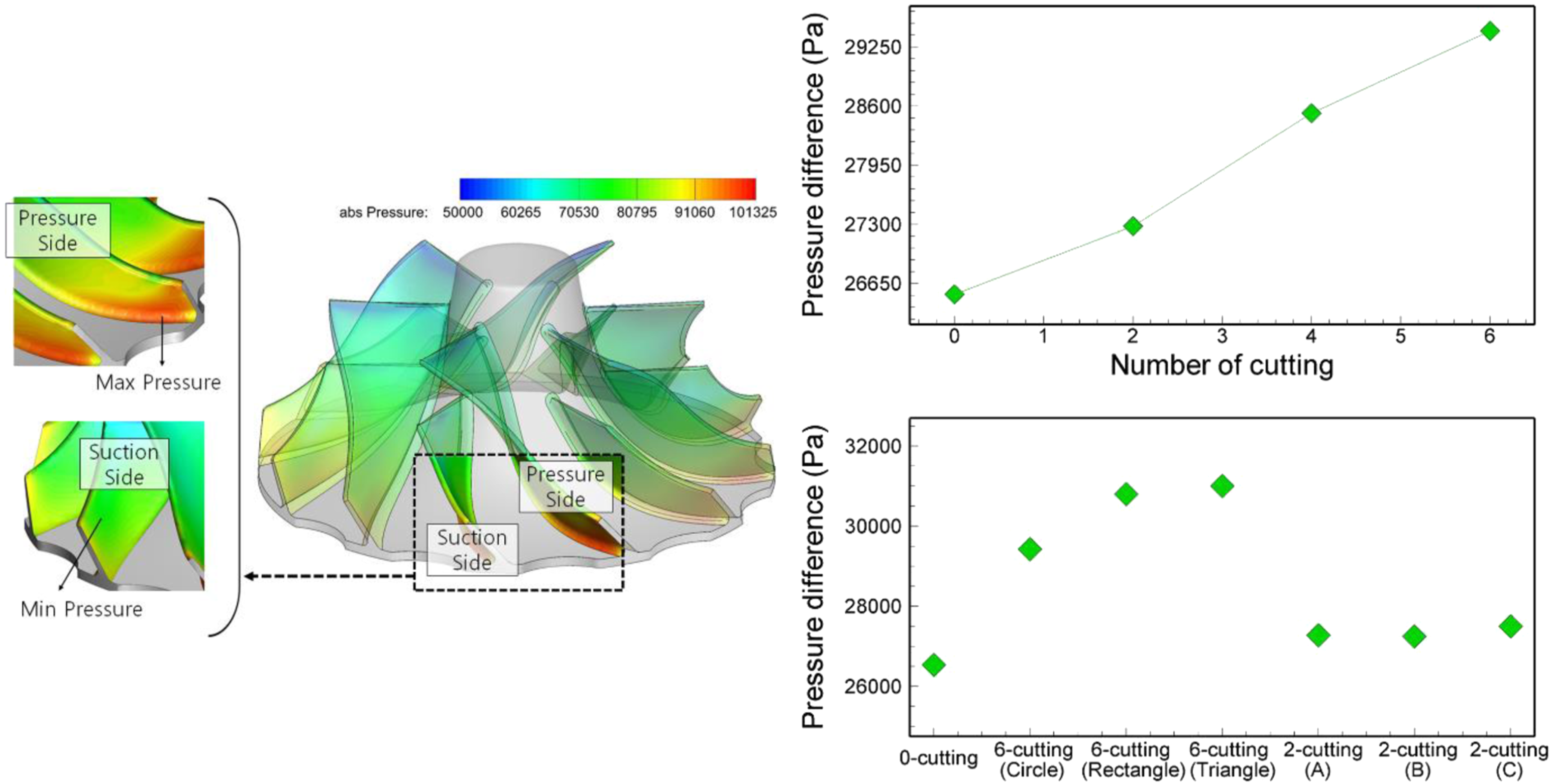
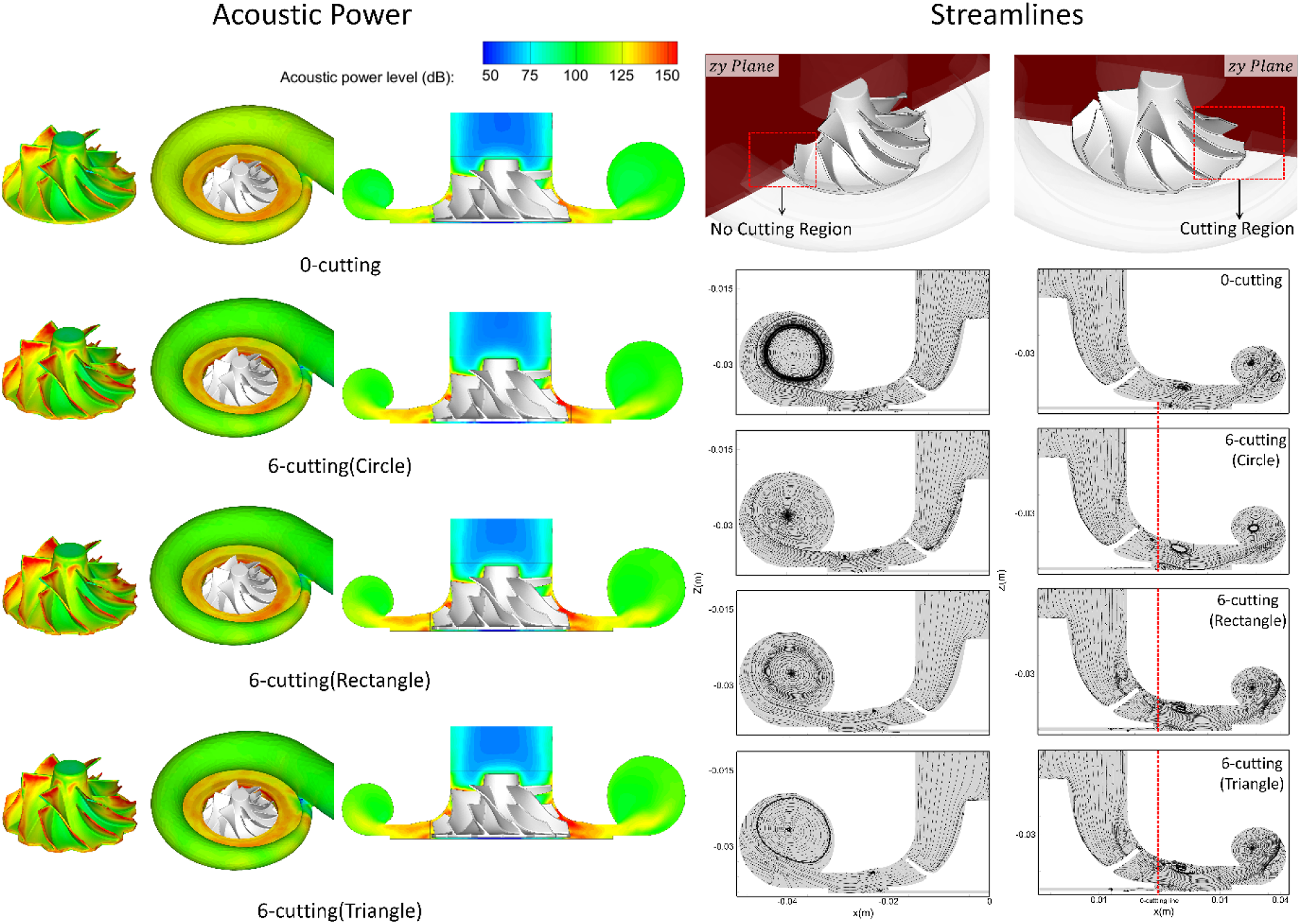
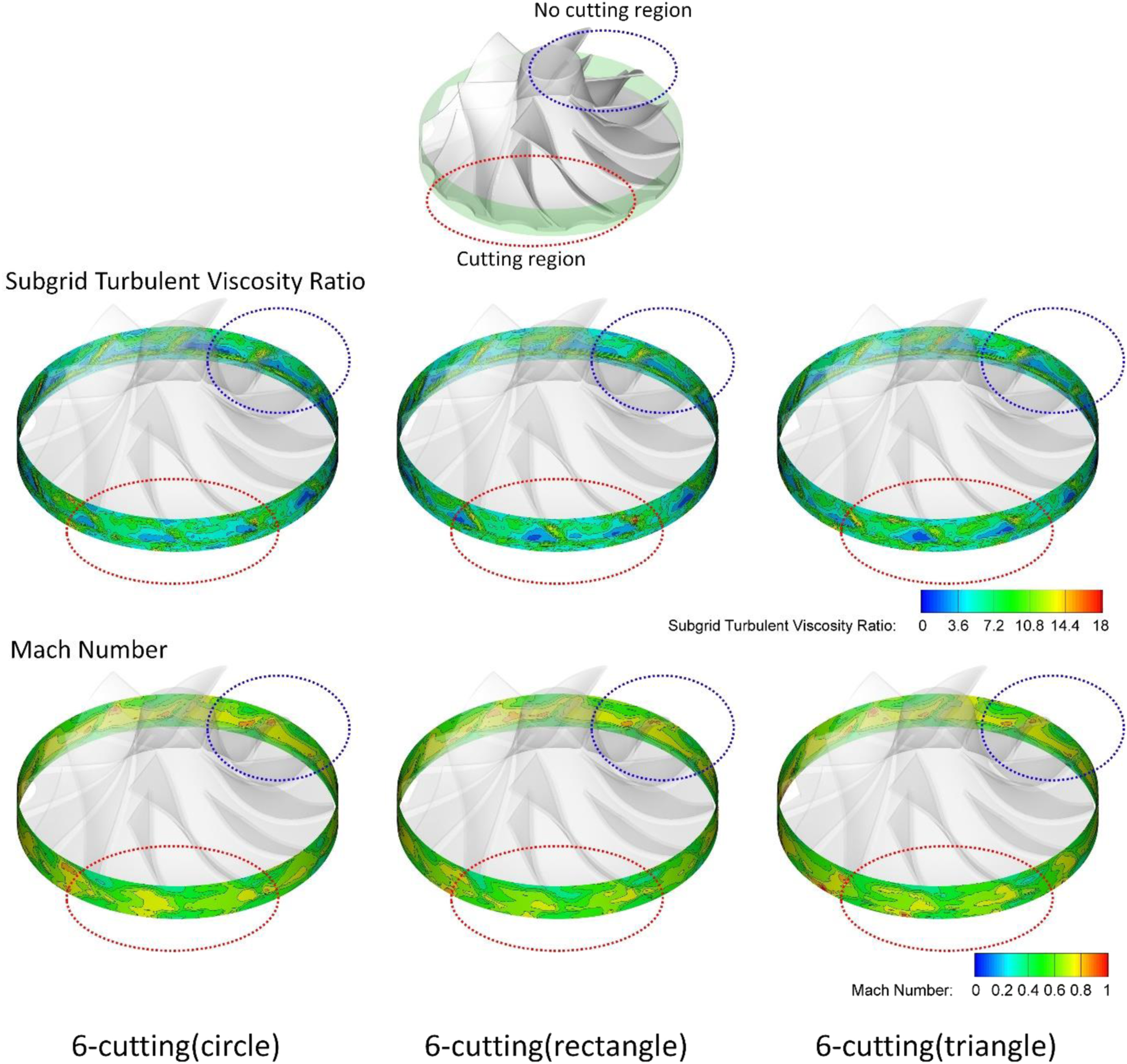
The acoustic power levels and streamlines of the 0-cutting case compared with the 2- and 6-cutting cases are shown in Figure 19 and 20. High acoustic power is generated by the blades in the region between the wheel and volute. In the blade region near the wheel inlet, the sound pressure is weakly affected for a wheel modified by cutting. However, the sound pressure in the region between the wheel and volute and in the blade region facing the shroud is strongly affected by the different wheel types. As shown in Figure 18, the pressure difference between the pressure and suction side increases with increasing numbers of cutting parts. Judging from this change in the pressure difference, the tip-clearance and secondary flows are changed by the different cutting parts. Consequently, noise generation due to the cutting of the compressor wheel is mainly caused by the varied tip-clearance flows produced by the wheel change. From Figure 19 and 20, the maximum sound pressure is predicted to be 145.2 dB for the 0-cutting case, 150.9 dB for 6-cutting case (circle), 153.5 dB for 6-cutting case (rectangle), and 154.9 dB for the 6-cutting (triangle) case. For the 2-cutting cases, the maximum sound pressure is 147.3 dB for type A, 147.3 dB for type B, and 148.2 dB for type C (see Figure 2 for the type definitions). This shows that it is advantageous for the shape changes produced by the cuttings to be concentrated in one place. When the cutting parts are spaced apart, as in type C, the flow-induced noise is increased. The distributions of the subgrid-scale stress and Mach number on the side surface of the wheel are shown in Figure 21. The subgrid-scale stress is related to small-scale flow fluctuations, and it is normalized by the laminar viscosity. The Mach number represents the combined effects of the large-scale velocity and thermodynamic state. This figure confirms the cutting effect on the flow field. The cutting parts weaken the feature of distinguishing the flows that have passed through the wheel blades. The effects of the splitter blades are weakening, and the flows are changing into flows feature between two main blades. Therefore, considering the wheel rotation, the turbulent flows near the wheel is characterized by the main blade frequency of 2fshaft. As shown in the 6-cutting (triangle) case of Figure 15 and 17, the difference between the dominant frequencies is 2fshaft and the reduced amplitudes of 2fshaft, 4fshaft, 6fshaft, 8fshaft, and 10fshaft are observed. It can be considered that this result reflects the above flow characteristics. Acoustic power for wheels with different types of 2-cuttings. See Fig. 2 for the definitions of the wheel types. Acoustic power for wheels with different types of 6-cuttings. Subgrid turbulent viscosity ratio and Mach number on the side surface of the wheel.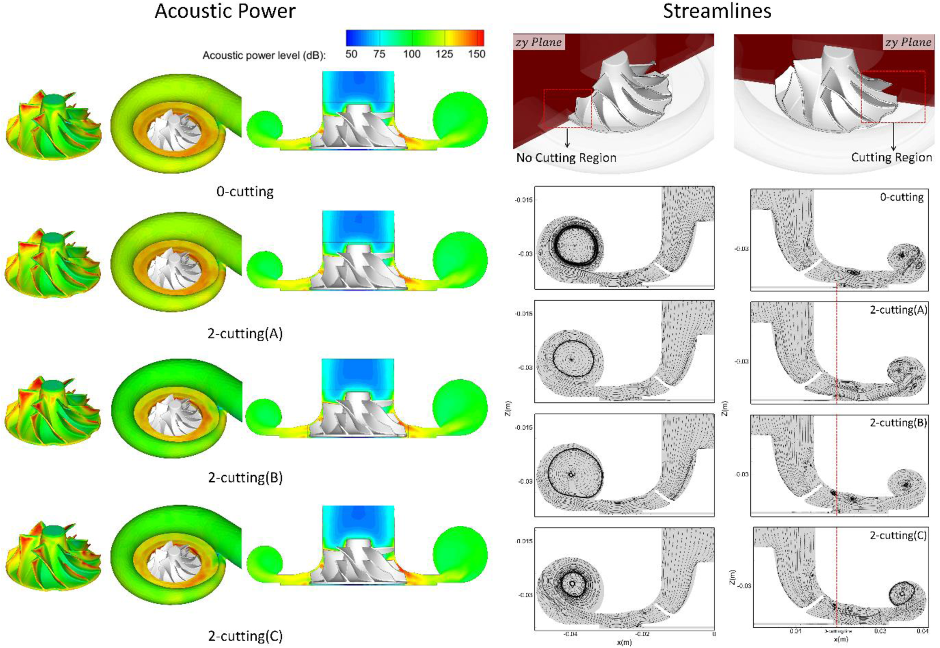
The averaged VAP sound pressure for the different cutting types is shown in Figure 22. The averaged acoustic power is obtained for different compressor wheels. When the number of circular cuttings is increased from 0 to 6, the averaged VAP values are 145.2 dB for the 0-cutting case, 147.3 dB for the 2-cutting case, 148.0 dB for the 4-cutting case, and 150.9 dB for the 6-cutting case. As the number of cutting regions increases, the averaged acoustic power increases almost linearly. For the 6-cutting cases, the circular cuttings produce the lowest acoustic power and the averaged VAP value is significantly changed by the cutting shape: 150.9 dB for the circular cuttings, 154.9 dB for the triangular cuttings, and 153.5 dB for the rectangular cuttings. The acoustic power from the triangular cutting is the largest, with a difference of approximately 4 dB above the circular ones. For the 2-cutting cases, the averaged VAP values depend on the cutting type and are 147.3 dB for type A, 147.3 dB for type B, and 148.2 dB for type C. The acoustic power changes weakly with the type of cut, but from the noise point of view it is not good to separate two cut parts. It is interesting that the variation of acoustic power with the cutting type is very similar to the variation of the pressure difference between the pressure side and the suction side of the wheel blade. It can, thus, be understood that the TCN is changed by the shape of the modified compressor wheel. Comparison of acoustic power for the different cutting types.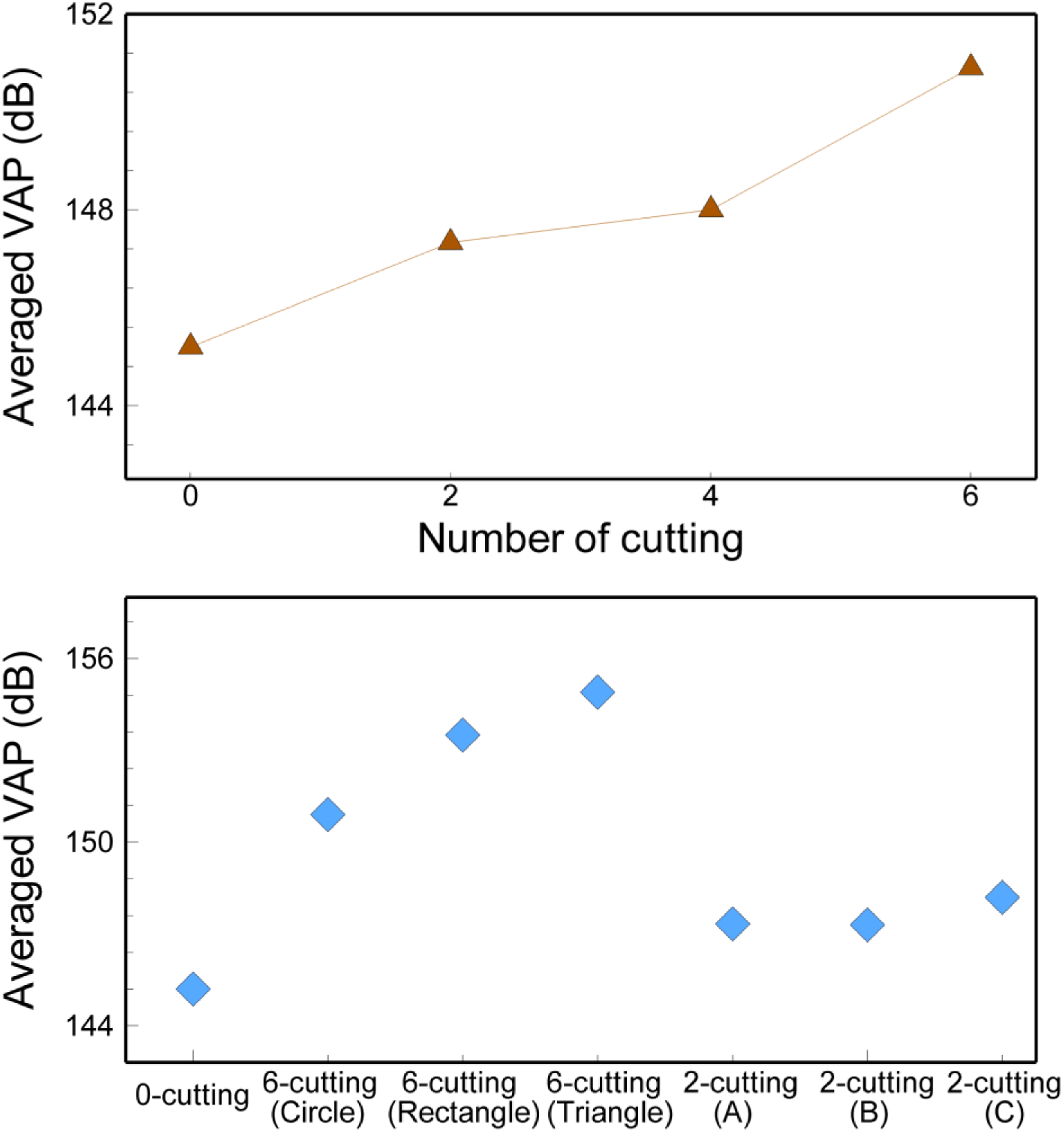
Conclusion
To correct an unbalanced mass distribution, the cutting process is generally performed on the compressor wheel of a turbocharger. To examine the effects of such shape changes on the resulting turbulent flows and flow noises, turbulent simulations using the RANS and DES models were performed. The cutting shape was selected to be circular, rectangular, or triangular. The turbulent flow fields and acoustic power based on the broadband noise and Ffowcs Williams and Hawkings models were investigated as the number of cutting parts increased from 0 to 2, 4, and 6.
To investigate the problem of balancing compressor wheels, an evaluation process using CFD was employed. This confirmed that the balance cuttings have the side effect of improving the rotation balance. The fluid forces due to the shape of the wheel have the potential to restore the eccentricity by approximately 50%.
A compressor wheel with the cutting parts near the wheel outlet shows similar performance curves regardless of the cutting types. From the variations of the velocity magnitude, pressure, pressure fluctuations, and turbulent kinetic energy, it is found that the cutting effects are concentrated at the wheel outlet between pairs of adjacent blades. In the region, the fshaft pulsation feature of the pressure and turbulent kinetic energy is not clearly seen in either the 0- or 6-cutting cases. However, a highly strained structure and wavelike variations of near the cut regions of the compressor wheel are observed, and the spectral densities close to the whoosh noise characteristics are enhanced.
The results of measurements of the acoustic power and sound-pressure level show that the dominant frequencies are proportional to fshaft. This tendency is clearer for the modified compressor wheels than for the 0-cutting case. For the 6-cutting (triangle) case, it was observed that the peaks at the harmonic frequencies 2ifshaft (i = 1, 2, …) are weakened. This feature was attributed to the acoustic pressure and flow characteristics of compressor wheels with reduced numbers of blades. The MPT noise, called the buzz-saw noise, is enhanced for compressor wheels modified with the cutting parts. In particular, TCN noises are generated with frequencies slightly larger than fBPF. The rectangular and triangular shapes of cutting are disadvantageous for noise reduction.
Footnotes
Declaration of conflicting interests
The author(s) declared no potential conflicts of interest with respect to the research, authorship, and/or publication of this article.
Funding
The author(s) disclosed receipt of the following financial support for the research, authorship, and/or publication of this article: This work was supported by Korea Institute of Energy Technology Evaluation and Planning (KETEP) grant funded by the Korea government (MOTIE) (20203030030070, Development of high temperature fuel recycle blower for Solid Oxide Fuel Cell system applied to buildings).