
Abstract
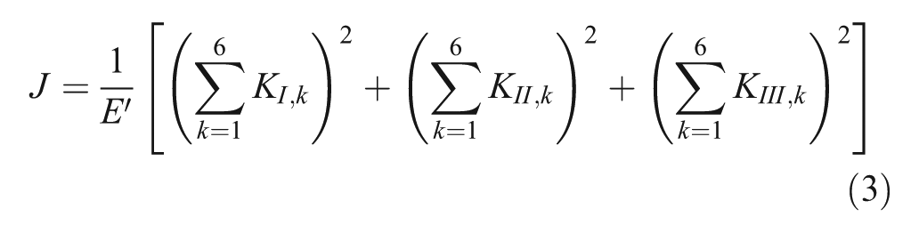
A damage detection scheme for multiple crack detection in beams is presented, based on a transfer matrix derived from beam element with two cracks. Based on fracture mechanics principles, a crack is modelled as a hinge, which provides an additional flexibility to the element. Each element is assumed to have two open-edge cracks and a new transfer matrix called two crack transfer matrix is developed using finite element method. Using an inverse approach, the transfer matrix is used to predict cracks in a beam. The state vector at a node includes displacements, forces and moments at that node; when it is multiplied with the transfer matrix, the state vector at the adjacent node can be obtained. The state vector formed at the starting node, known as initial state vector, needs to be estimated, from which state vectors at adjacent nodes are predicted using the transfer matrix. Displacement responses are measured at a few adjacent nodes in the structure. The mean square error between measured and predicted responses is minimized using a heuristic optimization algorithm, with crack depth and location in each element as the optimization variables. Two numerical examples, a cantilever and a sub-structure of a frame with nine members, are solved with two cracks in each element. The damage detection method is also validated experimentally by local identification of sub-structure of a fixed beam where the initial state vector is measured using strain gauges and accelerometers. Using this method, two cracks per single element were successfully identified. The two crack transfer matrix method is suitable for local damage identification in large structures.
Keywords
Introduction
Structural health monitoring (SHM) is a process by which the health of the structure is predicted using non-destructive approach. It is highly essential for civil, mechanical and aerospace structures, which undergo repeated cyclic loading after an impact loading or earthquake. Even small breathing cracks in the structural element may cause an unexpected loss; hence, it must undergo SHM process periodically. Generally, the crack detection process such as ultrasonic methods, optical methods, radiography, magnetic field methods, eddy-current methods and thermal field methods is used for damage detection. These methods are expensive and require that the zone of the damage is known a priori, and that the structural element to be inspected is accessible. As an alternate, vibration-based damage detection methods deserve further investigation.
Damage in the machine element or structure means not only the presence of discontinuities in the material but also include changes in the boundary conditions, loose machine fittings or fasteners such as bolts and nuts. The damage provides a local flexibility in the structural element, which reduces the natural frequency of the entire structure and dynamic responses as well. Gounaris and Dimarogonas 1 developed elemental compliance matrix for cracked beam element by assuming the crack increases the flexibility of the element due to strain energy concentrations in the vicinity of the crack tip under load. From that compliance matrix, elemental stiffness and mass matrices have been developed, and using them, the forced vibrational behaviour of a cantilever with open crack was studied. Chondros et al. 2 developed a continuous cracked beam theory for Euler–Bernoulli beams with single- and double-open-edge cracks. The crack was modelled as a continuous flexibility using the displacement field in the vicinity of the crack. Zheng and Kessissoglou 3 developed an overall stiffness matrix from the overall additional flexibility matrix rather than local additional flexibility matrix by which a better natural frequency and mode shape of structures were found. Krawczuk et al. 4 developed new finite element (FE) matrices for cracked beam elements using elasto-plastic fracture mechanics. FE procedure was applied with suitable boundary conditions at the crack with two different polynomial functions. Viola et al. 5 developed a new prismatic Timoshenko beam element with crack, and the effect of crack in stiffness and mass matrices was investigated. Khiem and Lien 6 determined natural frequencies of cantilever with multiple cracks using transfer matrix (TM) approach. Gounaris et al. 7 formulated compliance matrix for Timoshenko-cracked beam element by which identified crack in a cantilever by measuring coupled response. However, it is suitable for only one edge crack present in the beam, and it requires lot of nomograms for each frequency of vibration. Krawczuk 8 detected the crack in beam-like structures using wave propagation method using genetic algorithm (GA) and gradient search technique. Gao and Lu 9 used residual generation approach in measured acceleration response for damage detection in structural members.
Tee et al. 10 identified crack on 50 degree-of-freedom (DOF) shear model using observer Kalman filtre identification (OKID) and eigen realization algorithm (ERA)-based condensed model identification and recovery (CMIR) technique with global and sub-structural (SS) approach using GA. It has been proved that the SS approach identifies crack with better accuracy than the global structure approach. Prashanth and Shankar 11 detected damage on structures using a two-stage artificial neural network technique. Damages on a 6-story shear building, a 9-member frame structure and a 30-member frame were identified. Varghese and Shankar 12 identified cracks in a SS of the cantilever using combined acceleration matching and transient power flow balance. Philips et al. 13 identified damage in beams using displacement modes and distributed strain measurement. In the above algorithms, for each iteration, the large system matrices need to be solved, which consumes more computational time. As an alternative, TM and state vectors are introduced in this article. The size of the TM does not increase with respect to the total number of DOF of the model, thus reducing the computational effort.
Liew et al. 14 used TM in the field of rotor dynamics for transient response analysis of non-symmetrical unbalance flexible rotor. Ghasemalizadeh et al. 15 determined natural frequency and frequency responses for multirotor system supported on two bearings using TM. To the best of the author’s knowledge, Nandakumar and Shankar 16 were the first to propose using TM as an inverse problem for local identification in structures. They used TMs based on lumped mass and also consistent mass approaches to identify parameters of beam structures. Later, Nandakumar and Shankar17,18 extended the work to damped TMs and experimentally verified the TM-based identification strategy. The novelties of the present work are the following: (1) the above TM method is extended to crack identification and (2) a formulation is derived to identify two cracks per beam element, which is hitherto not reported in the literature.
Beam element with two cracks
A beam element of length
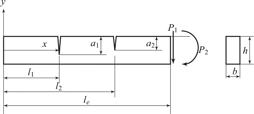
Beam element with two cracks.
Let

for

where
where
Substituting the above equation in equation (1)
The cross-section of the cracked beam element is shown in Figure 2. Let
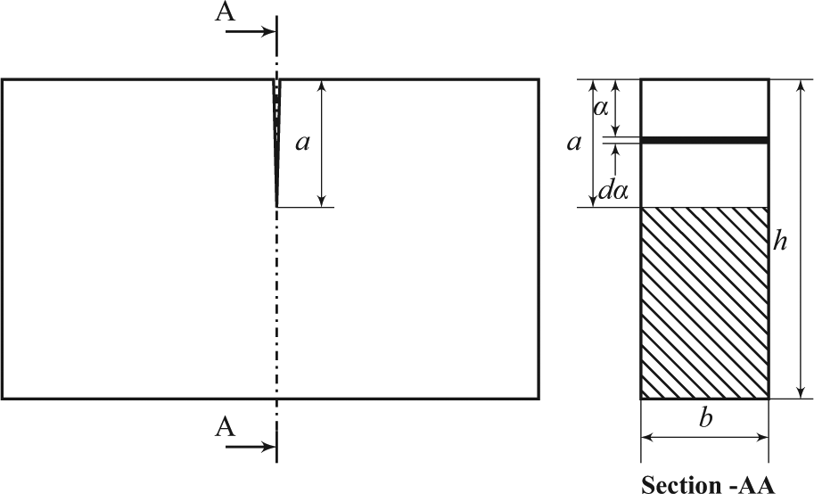
Cross-section at the crack.
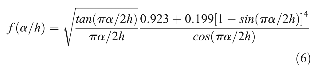
Consider a rectangular strip of thickness
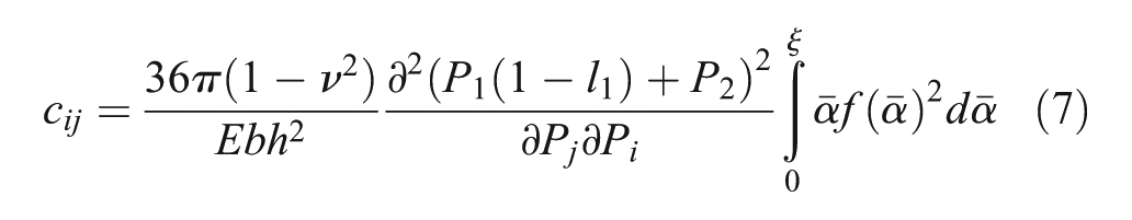
from equation (7)
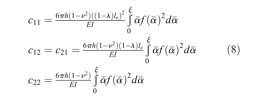
If the element is applied with only force,
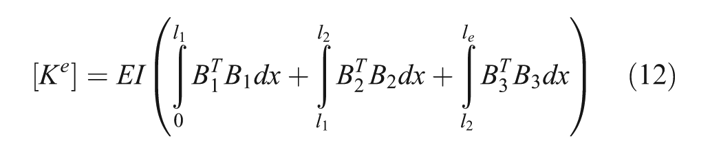
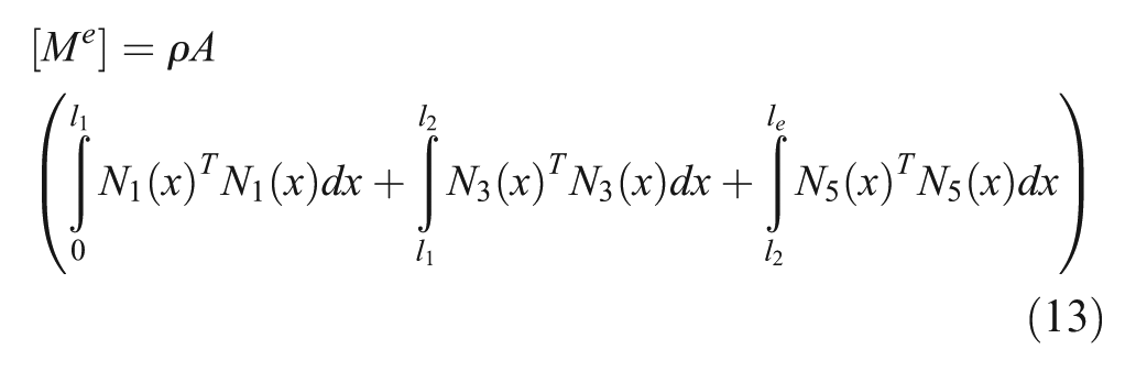
FE formulation
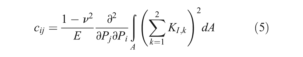
The additional flexibilities of the open cracks can be obtained from equation (9), the stiffness and mass matrices of the beam element with two cracks can be obtained by FE procedure. The cracked beam element, which is shown in Figure 1, is considered as three segments connected by two massless hinges of flexibility
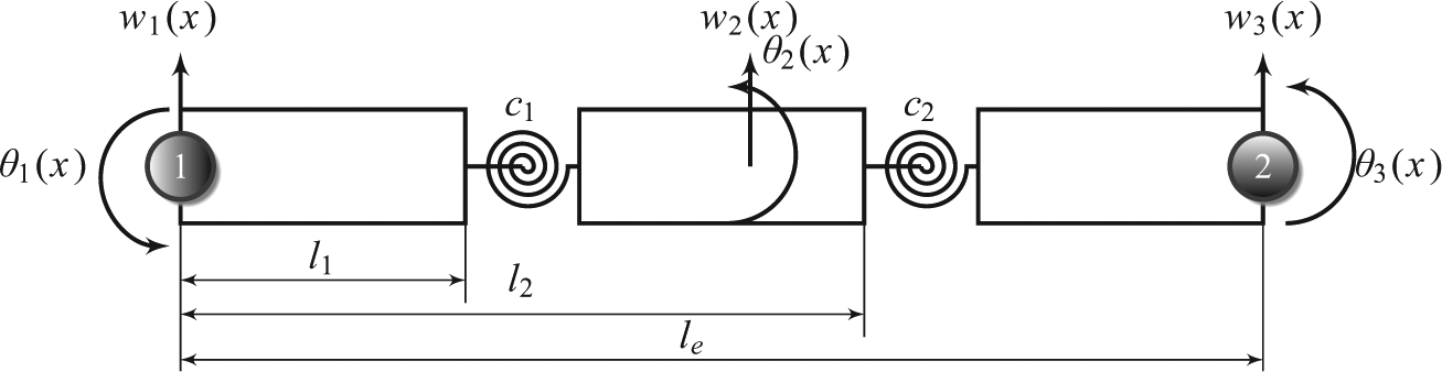
Equivalent model of cracked beam element.
Let
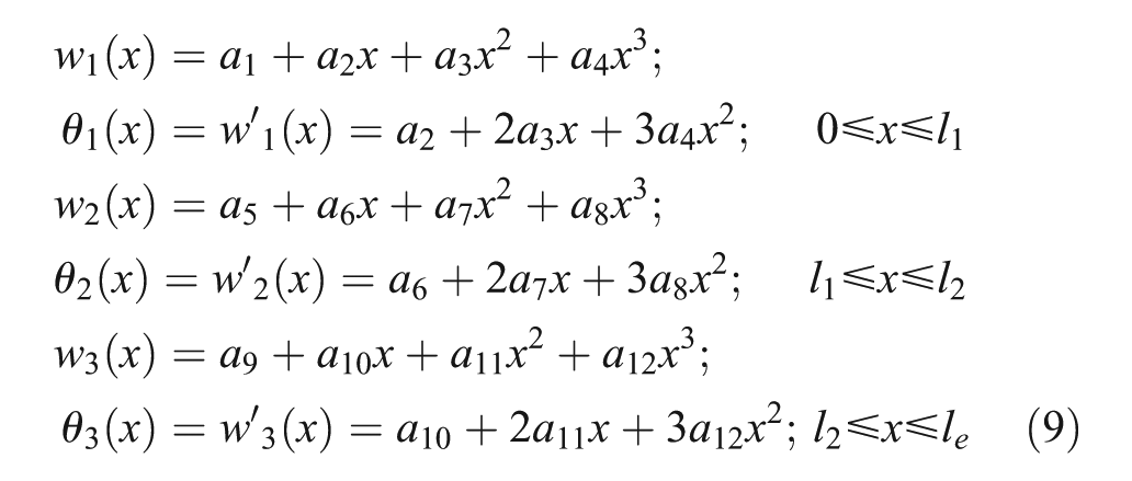
where a1–a12 are the constants. The following are the nodal values and conditions applied to the cracked beam element
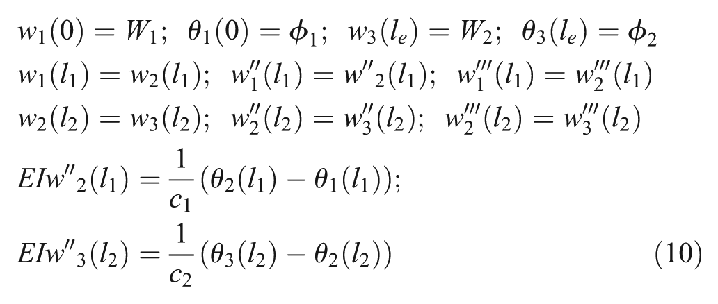
where
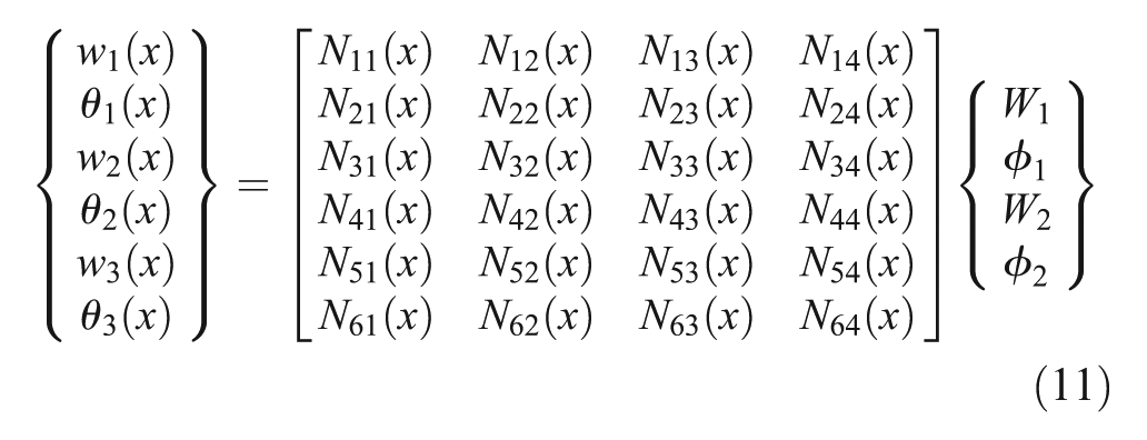
in the above equation, the shape function matrix is written as
where
TM formulation for two crack element
The characteristic equation for the second-order linear system is written for the two crack beam element shown in Figure 3

where

Let

the state vector at node 1

then equation (16) is written as
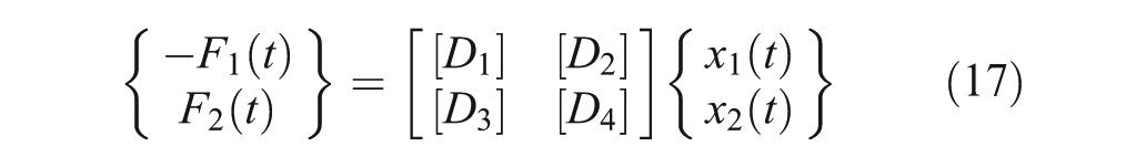
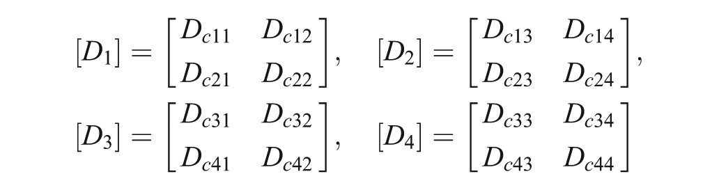
from equation (17)
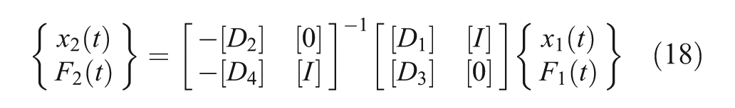
where
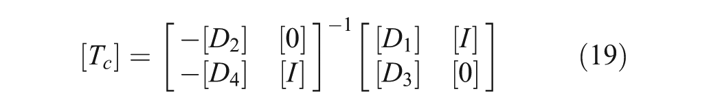
TM for multiple elements is calculated from elemental TMs. The state vector is estimated across
where
Crack detection by TCTM method
Cracks in a structure are identified using the newly developed TCTM by assuming the mass and flexural rigidity of the beam are known and two open cracks are present in each element. The unknown parameters are the normalized crack depth (
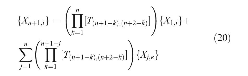
After formation of the initial state vector, the state vectors are obtained at adjacent locations by pre-multiplying with elemental TCTM using equation (20). Since the crack parameters in the TMs are unknown, they are searched by particle swarm optimization (PSO) algorithm within the feasible range of 0–1. The zero value of identified normalized crack depth shows the undamaged state of an element. The successive identification strategy16–18 is followed to identify crack parameters, where cracks are estimated progressively from starting node.
According to the successive identification strategy, the parameters of element(s) are identified between the nodes where the initial state vector is formed and its adjacent measured location. If a structure has
where
Numerical examples
The damage detection method using TCTM is applied on two examples, which are based on numerically simulated experiments. A cantilever with four cracks and a SS of a nine-member structure, which contains four cracks, are identified by TCTM method. The structural parameters such as mass and stiffness of the undamaged structure are assumed to be known, and the crack parameters normalized depth and location are identified. The structure is excited by known harmonic force at a point on the structure, and the acceleration responses are measured at few nodes and converted into displacement. All measured responses are numerically simulated using Newmark’s constant acceleration method for a time length of 3 s. Gaussian white noise of 5% of the root mean square (RMS) value of the numerically simulated response is added with all measurements to simulate experimental errors.
Example 1: Cantilever
A uniform slender cantilever of cross-section of 50 × 5 mm and length of 520 mm, which was used by Viola et al.,
19
is considered here with multiple cracks. Young’s modulus of the beam material (
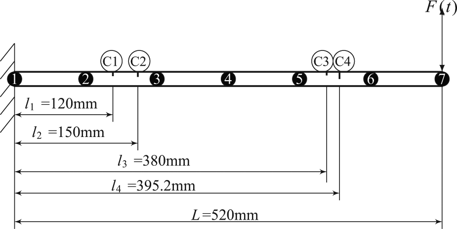
FE model of cantilever with multiple cracks.
The free end of the cantilever is subjected to a harmonic excitation of
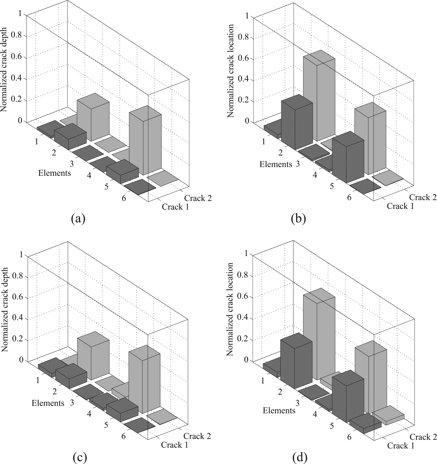
Identified crack parameters of cantilever with complete measurements: (a) identified crack depth (noise free), (b) identified crack location (noise free), (c) identified crack depth (5% noise) and (d) identified crack location (5% noise).
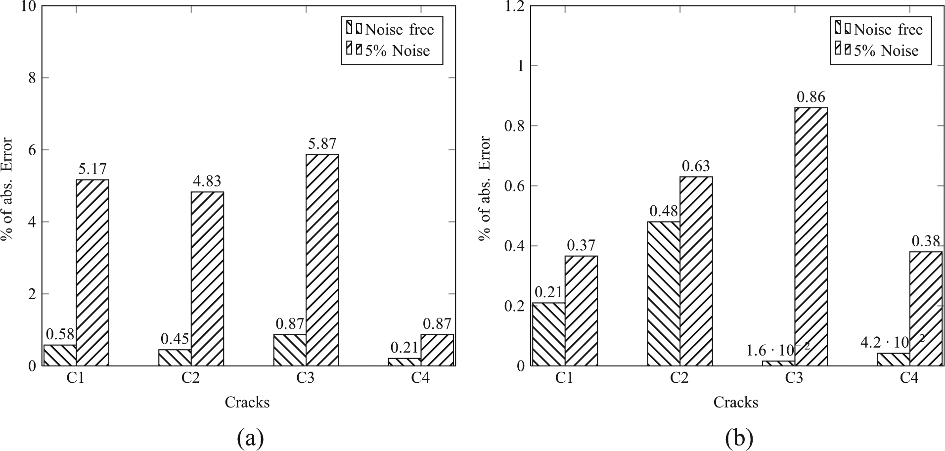
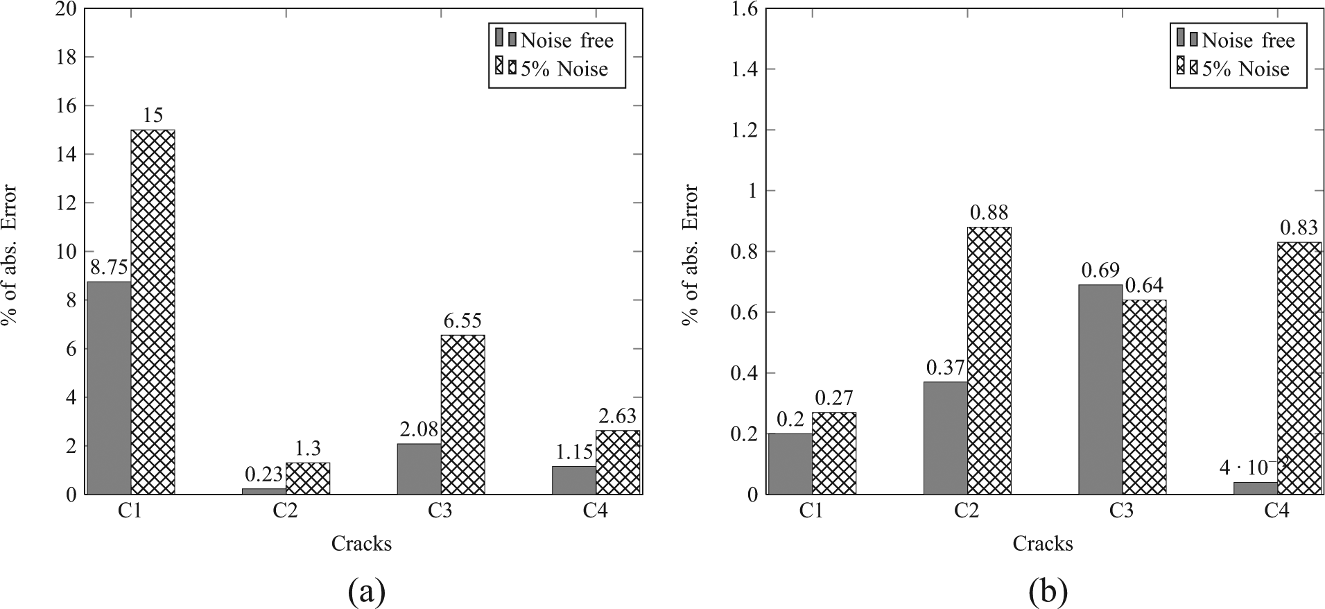
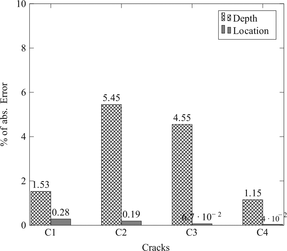
Absolute error in identified parameters of cantilever with complete measurements: (a) depth and (b) location.
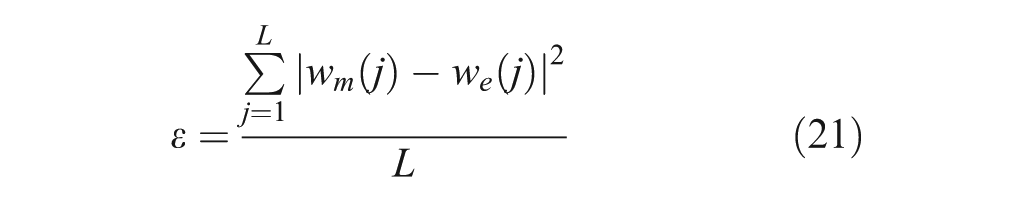
The cracks are identified with responses measured only at nodes 2, 4, 6 and 7. The elements between the starting node and the adjacent measured node (node 6) are considered. The response is predicted at the adjacent node with predicted crack parameters using equation (20). The MSE between the measured and predicted responses is minimized by PSO with 50 swarm size and 100 iterations in each cycle (total 400 iterations). The identified parameters are shown in Figure 7, and the absolute percentage of error is shown in Figure 8. In this case, the crack depth of 5% of beam height is identified with an error of 4.44% with noise-free measurement and 9.87% at 5% noise level in measurements. The error in its location is 0.07% without noise and 0.65% with 5% noise. The time taken for incomplete measurement case is 19 s. The percentage of error is comparatively high at cracks with small magnitudes since they show very small amount change in the dynamic responses. Hence, it is concluded that TCTM method is identifying crack with good accuracy and speed.
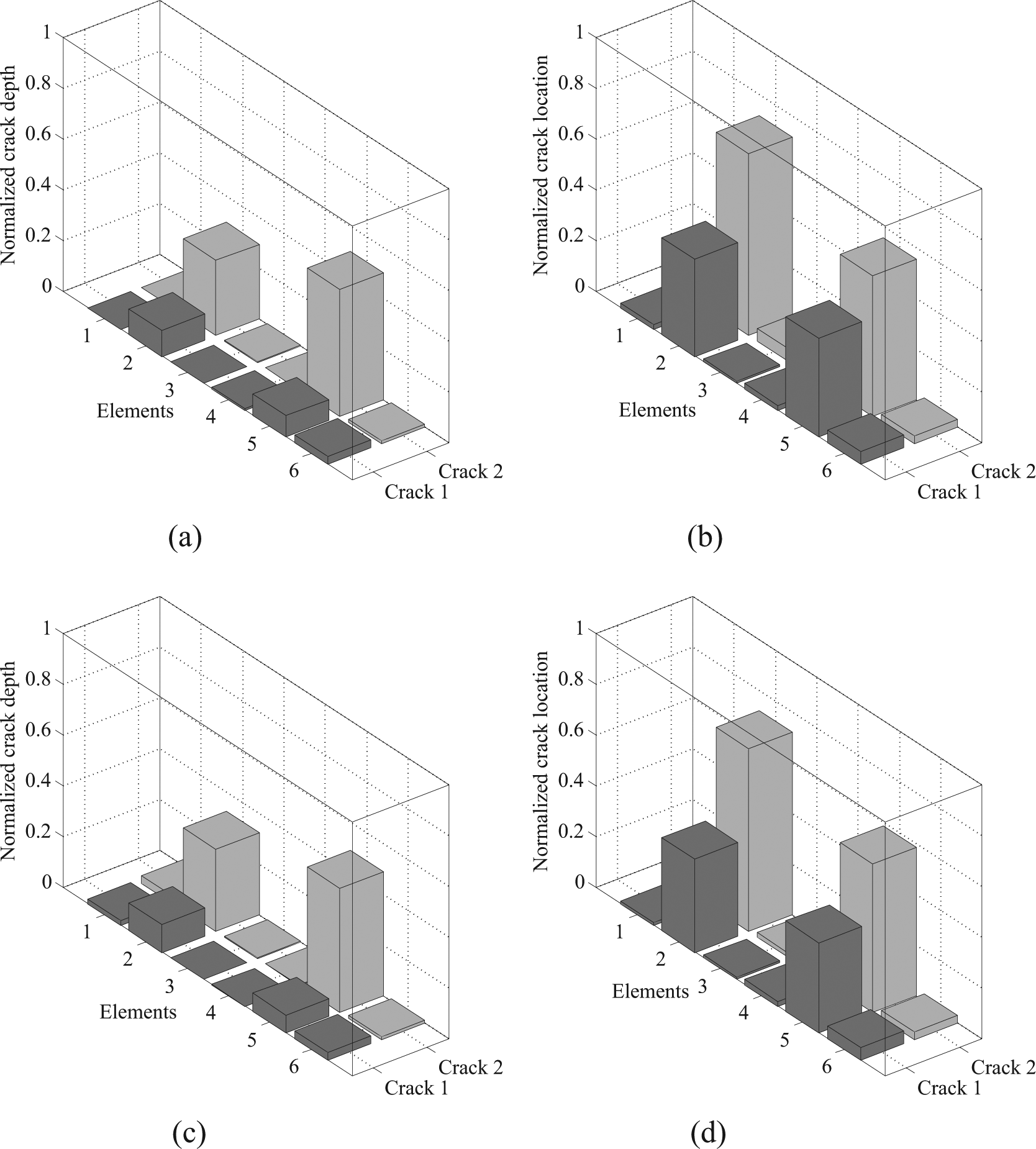
Identified crack parameters of cantilever with incomplete measurements: (a) identified crack depth (noise free), (b) identified crack location (noise free), (c) identified crack depth (5% noise) and (d) identified crack location (5% noise).
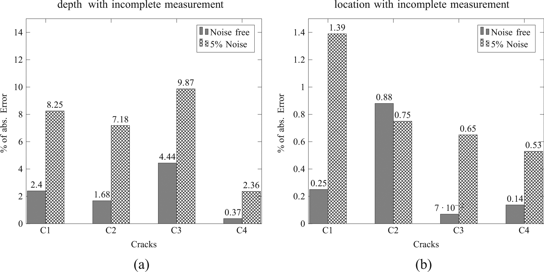
Absolute error in identified parameters of cantilever with incomplete measurements: (a) depth and (b) location.
Next, the results are compared with other published studies. Viola et al. 19 identified a single crack of depth of 50% of beam height, as located in this problem using a frequency-domain method from experimentally obtained measurements of unspecified noise content. The percentage of error in identification was 2.5% in crack depth and 0.53% in absolute crack location. The crack parameters identified by TCTM method for the same depth and location have an error of 0.21% in depth and 0.04% in absolute crack location using noise-free measurement. The errors are 0.87% in depth and 0.38% in location in the case of 5% noisy measurement. The method proposed by Viola et al. is capable of detecting only one crack, whereas TM method can able to detect multiple cracks in the structure. The same problem was also solved by Varghese and Shankar 20 using combined acceleration and power flow matching method. They have reported that the percentages of errors in identified crack depth and location were 0.92% and 0.5%, respectively, without noise, and 1.72% and 2.8%, respectively, with 5% noise. The TCTM method identified a crack of depth of 0.5% of beam height with an error of 0.87% in depth and 0.38% in absolute crack location with 5% noisy measurement. The mean computational time taken by the method proposed in Varghese and Shankar 20 is about 3000 s, whereas the mean time taken by the TCTM method is 14 s. This shows that the TCTM method identified multiple cracks in the cantilever and performs better than the other two damage detection methods in terms of accuracy and speed.
Example 2: SS of frame
A frame structure with nine slender beam members is supported as shown in Figure 9(a) used in Nandakumar and Shankar
18
for structural parameter identification (without crack). The cross-section of each member is 12 × 6 mm. The density of the frame material is 7800 kg/m3, and its Young’s modulus (
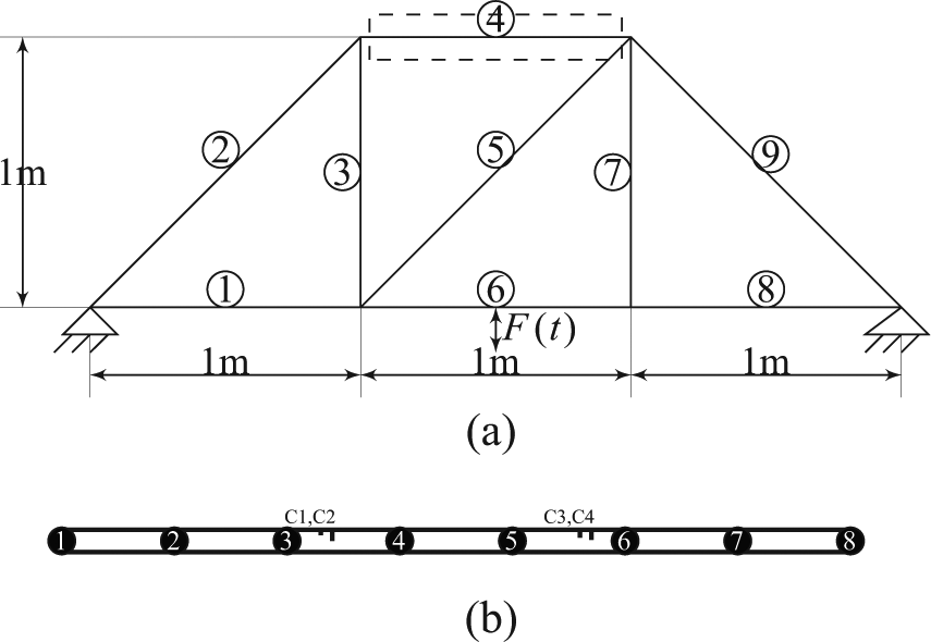
Frame structure: (a) global structure and (b) sub-structure of member 4 with 8 nodes.
In a general structure of this type, the bending moment and shear force in the initial state vector have to be obtained by strain measurements using the relations and procedure discussed in Nandakumar and Shankar16–18 and is briefly presented here (Figure 10).


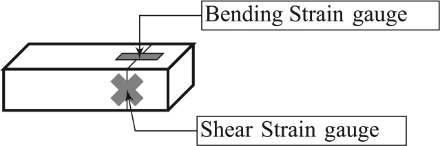
Strain gauge arrangements at starting node.
where

where
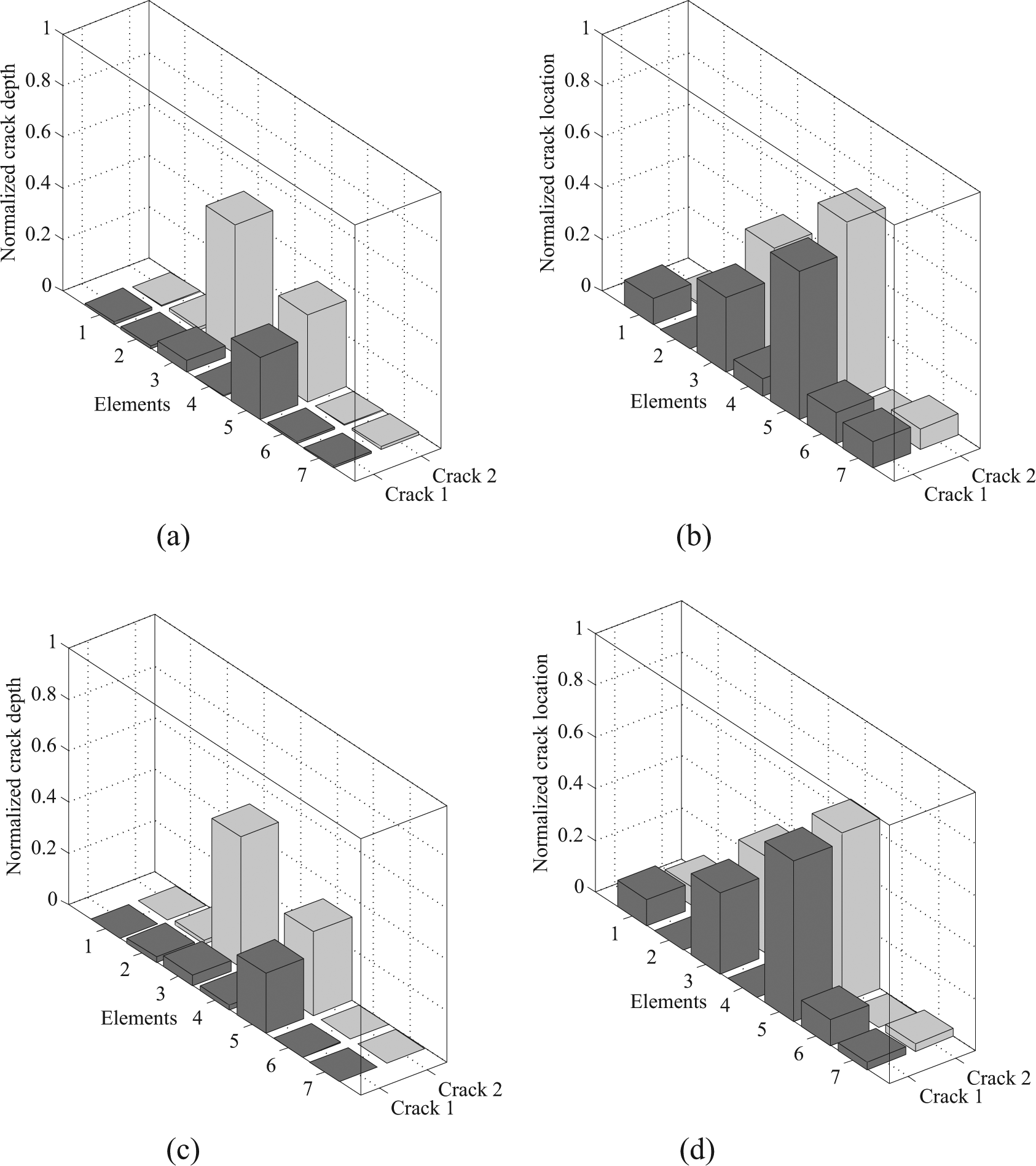
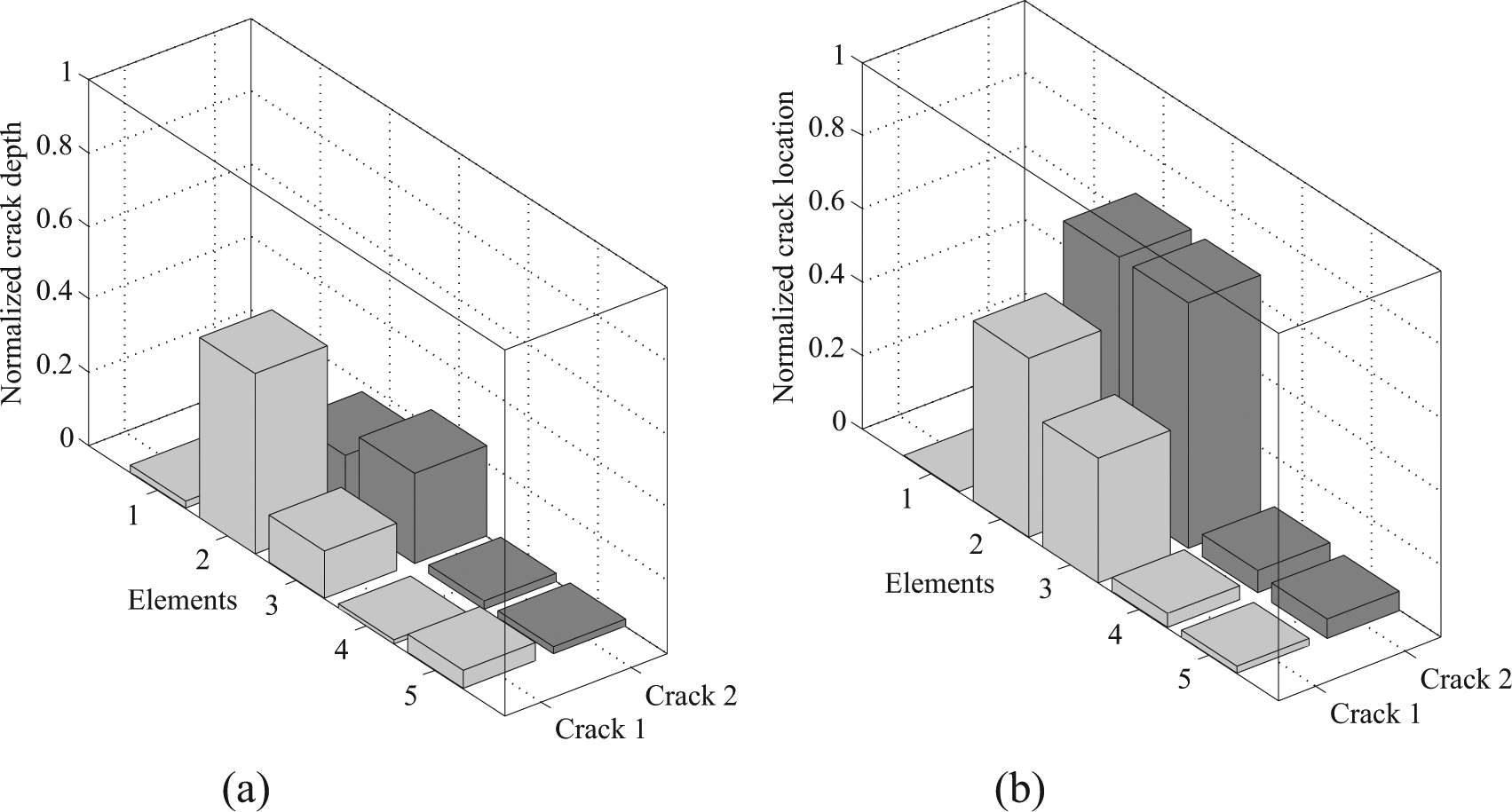
Identified crack parameters of SS of frame structure: (a) identified crack depth (noise free), (b) identified crack location (noise free), (c) identified crack depth (5% noise) and (d) identified crack location (5% noise).
Absolute error in identified parameters in SS of frame: (a) depth and (b) location.
Also in this example, the crack with less depth is identified with more error. However, the percentage of error is within the acceptable limit. From this example, it is clear that the TCTM is capable of identifying cracks in any SS with good accuracy and speed. Hence, it is suitable for identifying local crack parameters of any SS without modelling its global structure.
Experimental validation: SS of fixed beam
The TCTM method is experimentally validated by a SS of a fixed beam. A beam made of acrylic material with cross-sectional dimension of 25 × 12 mm and length of 671 mm was fixed at both ends, as shown in Figure 13(a) (same experiment was carried out in Nandakumar and Shankar17,18 for intact beam). The modulus of elasticity (
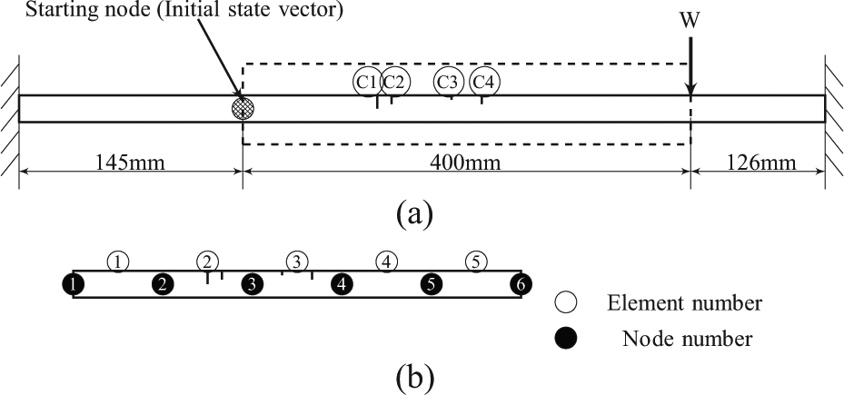
Experimental model of fixed beam: (a) global structure and (b) sub-structure.
The SS is divided into five FEs each of length 80 mm. The first two cracks
The experimental set-up of fixed beam is shown in Figure 14(a) and the close-up view of the multiple cracks in the beam is shown in Figure 14(b). To measure dynamic response, one DYTRAN miniature accelerometer of 2 gm mass with sensitivity of 107 mV/g and acceleration range of 50 g was fixed at each node to measure translational acceleration, and two accelerometers were fixed at the initial node 1 with centre-to-centre distance of
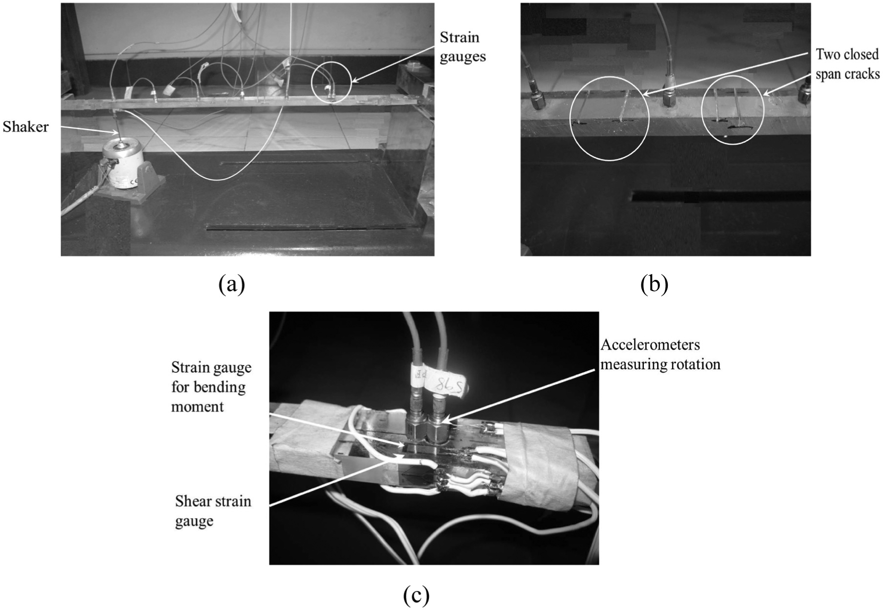
Experimental set-up of fixed beam: (a) global structure, (b) cracks in the beam and (c) strain gauge and accelerometer arrangement at initial node.
From the acquired data, a portion of data length of 3 s is considered for parameter identification. The angular acceleration at the initial node 1

The translational acceleration at the initial node is the mean value of acceleration measured by two accelerometers. Both translational and angular accelerations were converted into respective displacement responses. The bending moment and shear force responses at the initial node 1 were calculated from the measured bending and shear strain responses using equations (22) and (23) and the state vector at the node 1,
Experimentally identified crack parameters of SS of fixed beam: (a) identified crack depth and (b) identified crack location.
Error in identified parameters of SS of fixed beam.
It must be noted that the crack formulation used here (as well as Viola et al. 19 ) is applicable for thin cracks, and in the numerical simulation examples, good results were obtained. Hence, the TCTM method proposed here would be able to detect thin cracks. Also, in this experiment, the crack depth of small magnitude has more error in identified values. The strategy of applying TCTM method anywhere in a structure by measuring the initial state vector using strain gauges is proved here. This illustrates the suitability of TCTM method for local identification in a large structure.
Conclusion
A new TM method is proposed in this article to detect multiple cracks in beam-like structures. The TCTM is developed from the FE theory of beam element with two cracks. In simple structures like cantilever, the initial state vector is readily formed at a starting node by measuring displacements, bending moment and shear force responses. However, in a general structure, such as the nine-member frame studied here, the initial state vector has to be obtained by acceleration and strain measurements. Two cracks are assumed in each element, and the successive identification strategy of TCTM method is adopted here since it is fast and accurate. Two numerical examples were studied with complete and incomplete set of measurements. They are a cantilever with multiple cracks and a nine-member structure with multiple cracks (two cracks in each element). The typical error in identified crack parameters ranges from 0.05% (without noise) to 15% (with 5% noise). The TCTM method is validated experimentally by identifying crack parameters of varying depth and location in a SS of a fixed beam with good accuracy. Furthermore, this algorithm is suitable for local damage detection in a large structure, where the initial state vector can be estimated.
Footnotes
Declaration of conflicting interests
The authors declare that there is no conflict of interest.
Funding
This research received no specific grant from any funding agency in the public, commercial or not-for-profit sectors.