
Abstract
This study demonstrates an application of a previously proposed modal and wavelet analysis-based damage identification method to a wind turbine blade. A trailing edge debonding was introduced to an SSP 34-m blade mounted on a test rig. Operational modal analysis was conducted to obtain mode shapes for undamaged and damaged states of the blade. Subsequently, the mode shapes were analyzed with one-dimensional continuous wavelet transformations for damage identification. The basic idea of the method is that structural damage will introduce local mode shape irregularities which are captured in the continuous wavelet transformation by significantly magnified transform coefficients, thus providing combined damage detection, localization, and size assessment. It was found that due to the nature of the proposed method, the value of the identification results highly depends on the number of employed measurement points. Since a limited number of measurement points were utilized in the experiments, only certain damage-sensitive modes, in which pronounced damage-induced mode shape changes occur, are applicable for valid identification of the damage.
Keywords
Introduction
While failure can happen in any structural component of the wind turbine, one of the most common and critical components to fail is the blade. 1 Here, several damage types can occur, 2 and in extreme situations, the entire blade can be destroyed. Since the blades account for 15%–20% of the total wind turbine costs, 3 a great need in a dedicated blade structural health monitoring (SHM) system, facilitating three-level damage identification, that is, detection, localization, and assessment (cf Rytter 4 ), was identified. The different proposed blade SHM methods utilize a wide range of quantities such as temperature, noise, and vibration. As described in Skov et al., 5 the applicability of each of these methods is primarily tested on the basis of controlled laboratory tests, or by finite element (FE) simulations. With both these methods, significant simplifications and idealizations are made with regard to, among other things, environmental effects. Under these conditions, several simple methods comparing pre- and post-damage quantity values, for example, modal parameters, have exhibited potential for damage detection. However, under conditions that are more realistic, these methods are inapplicable since environmental effects and noise contamination typically will conceal the direct changes in the previously mentioned quantities. As an example, it is stated in Salawu 6 how environmental effects can account for up to 5% changes in eigenfrequencies, which, as is also demonstrated in this study, cannot be expected to be exceeded by damage-induced eigenfrequency changes. Due to the general inadequacy of the simple methods, current research within the field of blade SHM is leveled mainly at developing more sophisticated and robust methods that, for example, include advanced signal processing or statistical analysis. 7
This article documents the application of an early proposed vibration-based method, employing continuous wavelet transformation (CWT) of spatial mode shape signals for damage detection, localization, and assessment in a full-scale wind turbine blade. CWT has been utilized extensively for identifying structural damages in both simple beam- and plate-like systems (see, for example, Douka et al., 8 Rucka and Wilde 9 and Cao et al. 10 ) and more complex structures such as small-scale wind turbine blades. 11 In the latter study, CWTs were used to identify cracks in a residential-sized wind turbine blade. This was done on the basis of mode shapes derived through experimental modal analysis (EMA), where an impact hammer was used for excitation. In this study, operational modal analysis (OMA) is used to obtain the mode shapes, and this means, we can examine the applicability of the proposed damage identification method for blades under conditions that resemble in-service conditions more closely. Additionally, this article uses a simple damage indicator, inspired by the modal assurance criterion (MAC), which expresses the similarity between pre- and post-damage wavelet transforms.
The article is organized as follows: the first part describes the test object, the damage, the measurement system, and the conducted experiments, while the following part gives the basics of CWT and describes the application of the method to the mode shapes.
OMA of SSP 34-m blade
Test object
A 34-m-long wind turbine blade, designed and manufactured by SSP, was mounted on an indoor test rig as shown in Figure 1. The SSP 34-m blade is made from epoxy fiberglass and has a mass of 4600 kg. 12
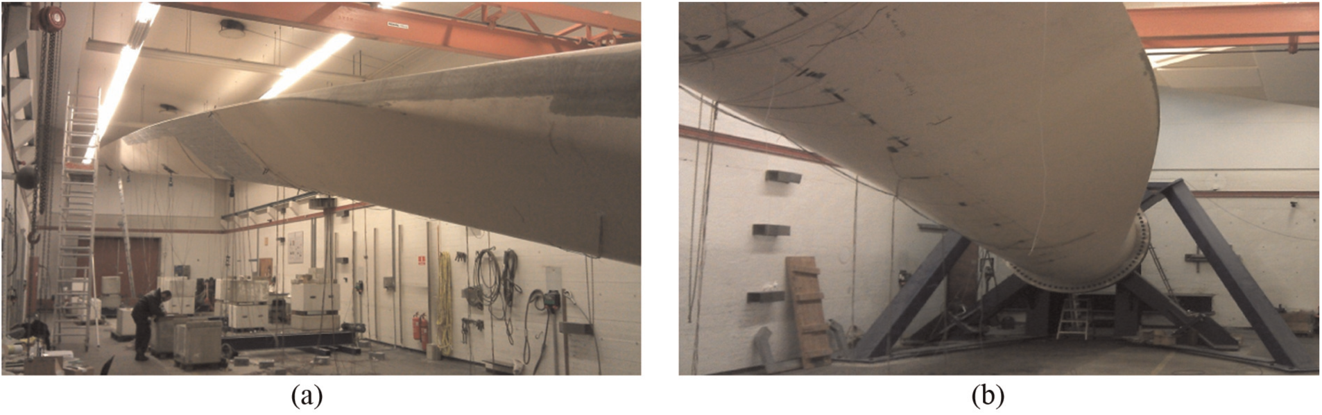
SSP 34 m blade mounted on the test rig: (a) root-to-tip view and (b) tip-to-root view.
Measurement system
The measurement system consisted of 20 triaxial accelerometers (Brüel & Kjær Type 4524-B) mounted on leading and trailing edges at 10 stations along the blade (see Figure 2(a) and (b)). The distances between the neighboring stations differed along the blade, from 4100 mm at the blade root to 2000 mm at the tip.
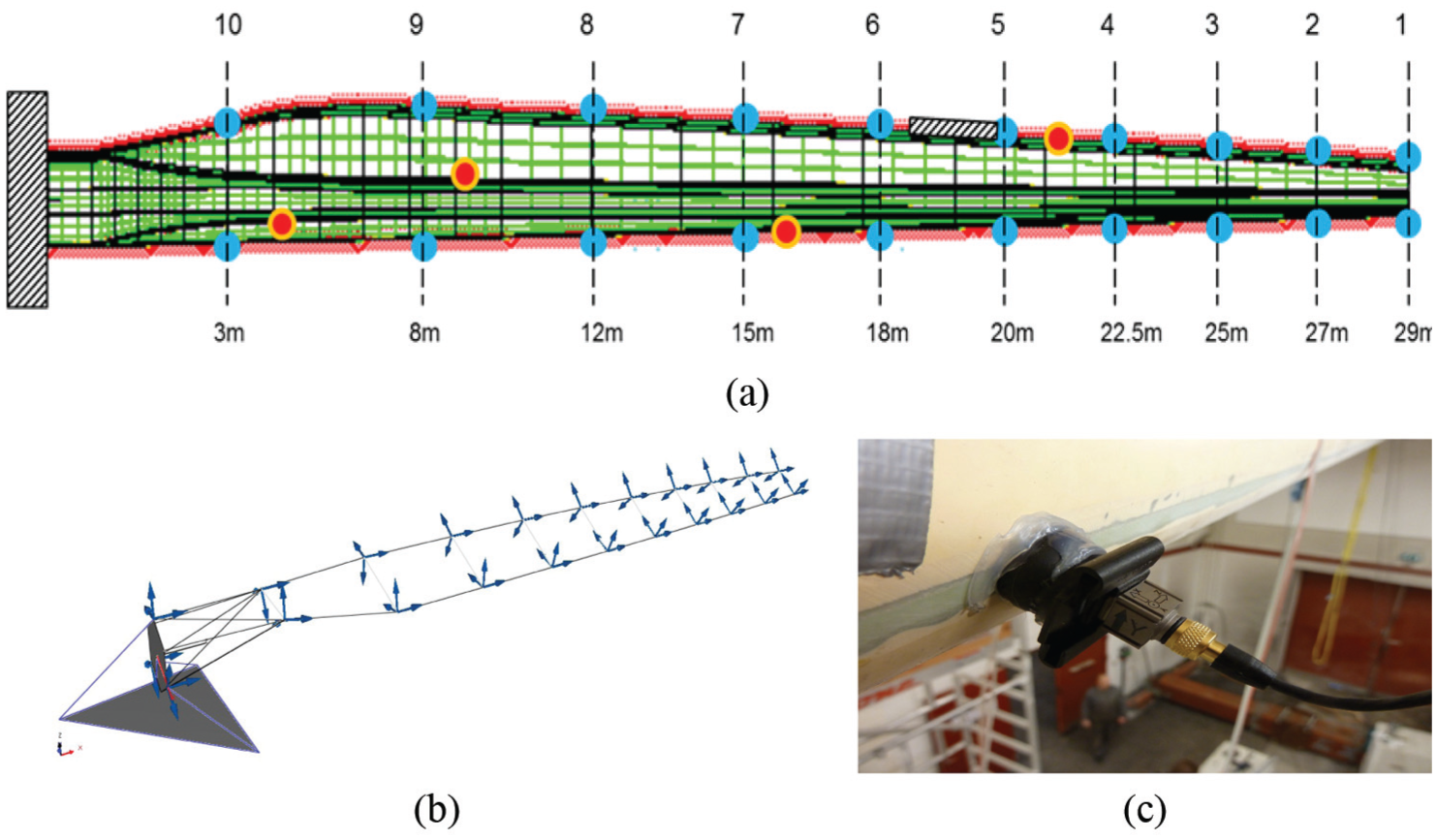
Measurement system setup for SSP 34 m blade: (a) overview of input (four red dots), output (20 blue dots) and damage (hatched box) locations; (b) accelerometer location and orientation; and (c) utilized accelerometers (Brüel & Kjær Type 4524-B) mounted on a swivel base (Brüel & Kjær UA-1473).
The location and orientation of the accelerometers have a key importance for getting correct mode shapes: their location and orientation in reality should be as close as possible to the coordinates and orientation of measurement degrees of freedom (DOFs) documented in the modal analysis software. In this project, this was achieved by using a dedicated template that was aligned against the foil profile at the stations, and the accelerometers were fixed on swivel bases according to the template. In Figure 2(c), a picture of an accelerometer mounted on a swivel base is shown.
Due to large distances between measurement points, it was advantageous using a distributed data acquisition system based on five, 12-channel, Brüel & Kjær LAN-XI modules Type 3053-B-120. Each module served two stations, that is, four triaxial accelerometers, and was placed near the sensors, therefore keeping the length of the accelerometer cables minimal. The modules were powered via an Ethernet cable, which was also used for data transfer and modules synchronization. It should be noticed that for real-life applications, the wired setup presented here should be replaced by a wireless one due to rotor rotation. Several ways of implementing such a setup are possible; one of them, which includes wired sensors on the rotor but wireless data transfer from the rotor to the nacelle, was described in Tcherniak and Larsen. 13 The setup described there proved its efficiency during a 6-month vibration monitoring campaign on an operating Vestas V27 wind turbine.
Data acquisition
According to OMA assumptions, the excitation is required to be distributed over the entire structure, it needs to be uncorrelated, and have a flat spectrum in the frequency range of interest. The blade was excited by several people hitting the blade at a number of positions (see Figure 2(a)), with heavy wooden sticks wrapped in foam. It is recognized that this excitation is quite different from what the blades experience during operation, namely, wind turbulence. However, it was shown in Yang et al. 14 and Ramirez et al. 15 that wind turbulence, just like the stick hits conducted in this study, excites a wide range of blade modes, which can be extracted from measured blade vibrations using OMA techniques.
Data from the accelerometers were recorded during approximately 7 min, corresponding to at least 500 oscillations at the lowest frequency of interest, which was identified as approximately 1.3 Hz.
Damage
To ensure that the damage introduced to the blade model is realistic, a study of typical structural blade damages was conducted and some of the critical ones were chosen for further work.
In Ataya and Ahmed, 2 15 blades of 300 kW wind turbines and 81 blades of 100 kW wind turbines, all with a lifetime range of between 16 and 19 years, were inspected. As a result of these inspections, several different damage types were found and subsequently categorized into three overall groups: cracks, edge damages, and debondings. Of these damage types, the most frequently occurring and severe were debondings plus longitudinal and transverse cracks near and at the blade edges. These all required structural repairs for the blades to operate properly (cf Ataya and Ahmed 2 ). Consequently, in this study, we decided to treat one of these specific damage types, namely, a trailing edge debonding (see Figure 3).
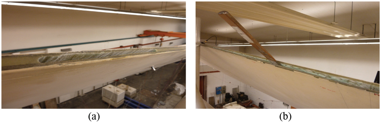
Debonding introduced in the trailing edge of an SSP 34-m blade: (a) original drilled debonding and (b) extended debonding.
The debonding was first introduced by drilling a series of holes perpendicular to the trailing edge, such that the glue connecting the shells was removed to yield the damage depicted in Figure 3(a). Subsequently, the debonding was gradually extended using a hammer and a chisel, resulting in the 1200-mm-long debonding shown in Figure 3(b). The extended debonding was located between 18,800 and 20,000 mm from the blade root.
Experiment and analysis
First, a series of OMA tests were performed on the undamaged blade and then the blade with different lengths of debonding. The damage was repaired according to the blade guidelines, and one more OMA test was conducted.
Since some additional, no-visible, inner-damage could occur when operating with the heavy hammer and chisel, it was decided to focus on two states: the state just before the damage was repaired and the state right after the repair. For each of these states, a 20-min long data set was available. The data set was split into three equal segments, each about 7 min long, and OMA was performed on each of the segments. OMA was also performed on the entire 20-min data sets to see whether more data would enhance the OMA algorithm performance. Therefore, in total, eight states were considered, with states 1–4 and 5–8 characterizing the “damaged” state and “undamaged” state, respectively.
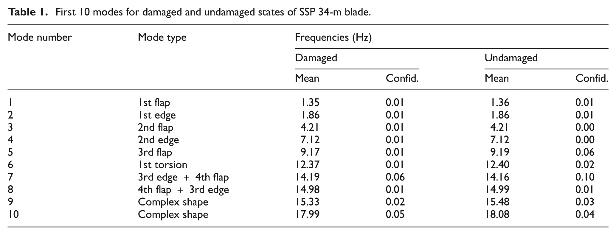
Brüel & Kjær OMA software Type 7760 was employed, and the stochastic subspace identification (SSI) algorithm was applied to the data. The 10 lowest modes were identified for all the eight states. In Table 1, the mode names and their frequencies (the mean and 95% confidence estimated from four averages) are presented. Additionally, the 10 mode shapes are plotted in Figure 4 for all the eight states.
First 10 modes for damaged and undamaged states of SSP 34-m blade.
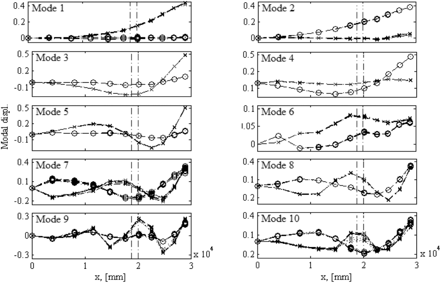
Flapwise (×) and edgewise (°) components of the first 10 mode shapes of damaged (…) and undamaged (−−) SSP 34 m blade. The dashed vertical lines mark the debonding location.
Damage identification in SSP 34-m blade
Using the presented OMA method, the modal parameters for the SSP 34-m blade were extracted. Even though the experiment was conducted in a well-controlled test rig environment, the changes in the natural frequencies due to the damage are comparable with the dispersion due to measurement noise (see Table 1). Furthermore, direct visual comparison of the mode shapes plotted in Figure 4 could not provide valid information to facilitate damage identification. Consequently, a more sophisticated and robust method, in the form of CWT, was employed.
Basics of CWT
The idea of the proposed damage identification method is to apply CWT to the spatial mode shape signals and thereby identify damage-induced irregularities in these signals. In this section, focus will be on describing the basics of CWT and its applicability in damage identification. The latter includes employment of mode shape signal interpolation and extrapolation procedures for improving the wavelet transform as a damage indicator.
By comparing the spatial mode shape signal,
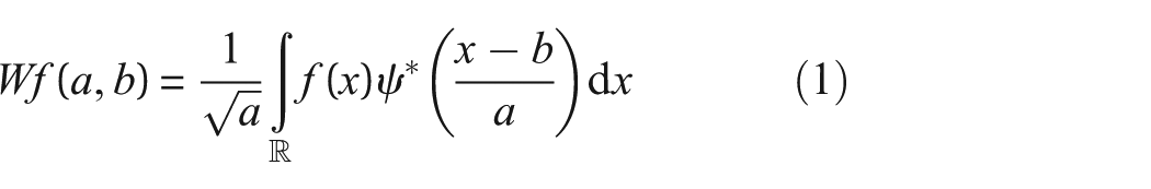
is obtained as the inner product of f(x) and the complex conjugated, indicated with the superscript *, of the so-called wavelet family. The wavelet family consists of functions constructed from dilations and translations of ψ, that is
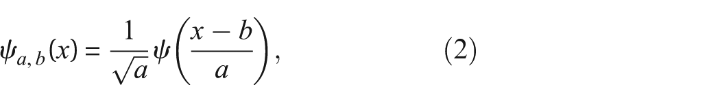
thus large values of a correspond to big wavelets and consequently coarse features of f(x), while low values of a correspond to fine details of f(x). In Equation (2), the factor
CWT for damage identification
Because of the effectively limited duration of the waveform, signals with abrupt changes can be better analyzed through a wavelet transform than through a Fourier transform. This is exploited in the proposed damage identification method, where the idea is that structural damage in the blade will induce local mode shape irregularities. These are then captured in the CWT by significantly magnified transform coefficients, thus providing level 3 damage identification. However, studies by Ciang et al., 7 for example, suggest that the effectiveness of CWT for damage identification is typically increased when the derivatives of the mode shapes are examined. This can easily be exploited since
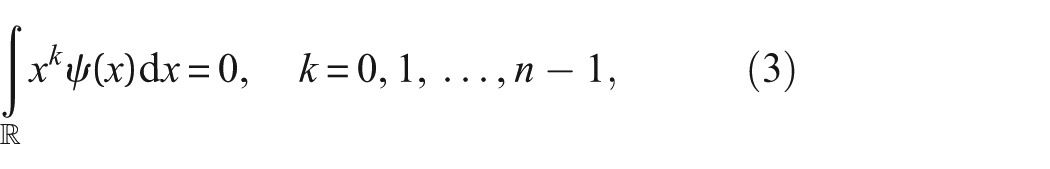
in which it is stated how a wavelet function has n vanishing moments when k = n − 1, meaning that a wavelet function with n vanishing moments is orthogonal to polynomials up to degree n − 1 and, thus, results in zero-valued wavelet coefficients for these polynomials. In this sense, the wavelet is unbiased and does not skew the function that is being transformed.
By rewriting Equation (1) into a convolution, the following is obtained
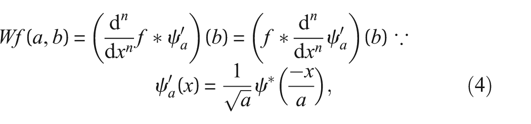
hence the CWT of the nth derivative of the mode shape is found directly as a convolution of the original mode shape and a wavelet function with n vanishing moments.
In this study, several wavelet functions, namely, real and complex Gaussians, the real and complex Morlet, the Ricker, Daubechies, and symlets, were tested, and it was found that a real-valued Gaussian wavelet function with four vanishing moments, as specified in, for example, Cao et al., 16 yielded the best results in the damage identification analyses of the SSP 34-m blade as this specific wavelet function provided the best tradeoff between enhancement of signal irregularities and adverse magnification of border distortions. Consequently, this particular wavelet was used. By employing scaling and position variables, the wavelet function was dilated and translated accordingly.
Mode shape interpolation
When conducting modal analysis to derive spatial mode shapes, a finite, and often reduced, number of measurement points are employed, resulting in introduction of discontinuities in the CWT due to low resolution. In order to overcome this issue, a smoothing scheme was applied in the form of cubic spline interpolation, where the original mode shape signals were oversampled with an increment of 10 mm.
Mode shape extrapolation
Since the CWT (cf Equation (1)) is an infinite integral transformation, adverse boundary effects will be introduced when employing the finite mode shape signal and wavelet function. These boundary effects will yield significant increases/decreases in the CWT coefficients at the boundaries which may conceal actual damage-induced CWT coefficient extrema. Therefore, an extrapolation scheme was included for removal of these boundary effects by shifting them to outside the interval in which the mode shapes are defined. Several studies, see, for example, Loutridis et al., 17 suggest using cubic spline extrapolation, but in this study, it was found that linear extrapolation utilizing the two outermost points at each end of the smoothed signal yields the most effective removal of adverse boundary effects. It is important to notice that this approach of course depends on the spatial resolution in the smoothed signals.
CWT of SSP 34-m mode shapes
By convolving the SSP 34-m mode shapes with the chosen Gaussian wavelet function, CWTs were derived for both damaged and undamaged states. By this means, it was found that valid damage identification can only be obtained when inspecting the CWTs of the flapwise components of mode shape 8, which is a combination of the fourth flapwise and third edgewise bending modes (see Table 1 and Figure 4). In Figure 5, this is depicted based on the full series measurements, that is, states 1 and 5. It was observed that similar results were obtained consistently for the other measurement states.
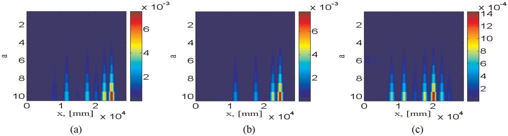
CWTs of the eighth mode flapwise components, with damage location x ∈ [18,800 mm; 20,000 mm]: (a) damaged (first state), (b) undamaged (fifth state), and (c) difference between damaged and undamaged.
Evidently, the damage-induced irregularities are not sufficient for the post-damage CWT to work as an independent damage indicator since CWT peaks occur at non-damaged locations as well. Referring to Equation (3), these non-damage-associated peaks should, theoretically, not occur (recall that the eighth mode is a combination of the fourth flapwise and third edgewise bending modes), but due to the experimental nature of the study (involving only few measurement points), signal irregularities arise. This is the case in both the undamaged and damaged states, thus when the CWTs from the undamaged states are subtracted from the post-damage counterparts, the maximum CWT coefficients are obtained at x≈ 20,000 mm, where the damage is located. That is, the debonding can be validly detected and localized. Regarding size assessment, it was observed that multiple distinct CWT peaks occur at non-damaged areas, making it troublesome to point out the peaks induced by the actual damage. Several studies, see, for example, Loutridis et al., 17 have suggested employing a statistical threshold value below which all CWT coefficients are set to 0 for eliminating the non-damage CWT peaks. A similar statistical approach was tested in this study, but it was found that a very fine measurement density is needed to provide a sufficient threshold value, and therefore, the approach was discarded.
As an alternative to visually inspecting the CWT plots for damage identification, a simple damage indicator was introduced for level 1 damage identification, that is, detection. The indicator is inspired by the MAC typically used in modal analysis (Cross-MAC), leading to the damage index (DI)
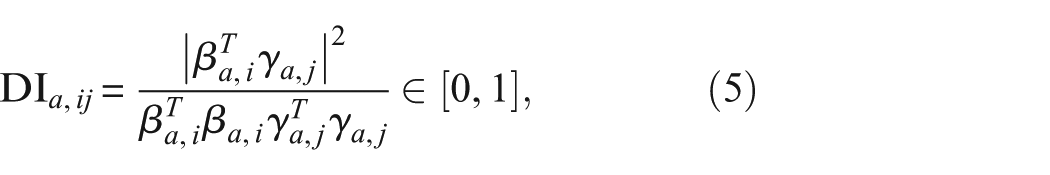
where βa,i is the CWT coefficient vector of the undamaged reference mode shape i at scale a, while γa,j is the CWT coefficient vector of either pre- or post-damage mode shape j at scale a, that is, γ
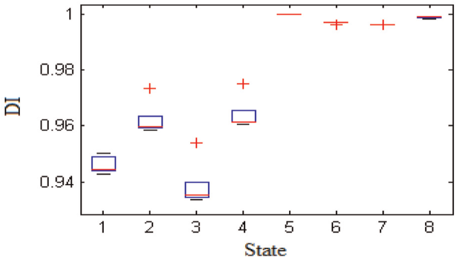
Box-and-whisker plot of DI values for flapwise components of mode shape 8, with state 5 as reference. The central mark in each box is the median, the edges of the box are the 25th and 75th percentiles, the whiskers extend to the most extreme data points not considered outliers (±2.7 times the spreading), and outliers are plotted individually.
Evidently, the DI values decrease in the post-damage states, that is, 1–4. The significance of these reductions is quantified through the box-and-whisker plot. Here, it is clearly seen that the DI value changes in the post-damage states are significant and cannot be categorized as measurement uncertainties, therefore implying that the changes must arise from the introduction of debonding.
Conclusion
The article deals with modal and wavelet analysis-based damage identification in wind turbine blades. The studied damage identification method is based on modal analysis for derivation of structural mode shapes, which are subsequently signal-processed in the spatial domain and analyzed by means of one-dimensional CWT. The method allows combined detection, localization, and assessment of structural damage. In the presented study, the abilities of the method were demonstrated by detection and localization of a 1.2-m trailing edge debonding of a 34-m blade. It was found that this type of damage could be validly detected and localized when comparing pre- and post-damage CWTs of the eighth blade mode. Regarding damage assessment in this mode, it was found that multiple distinct CWT peaks occur at non-damaged areas, thus it is troublesome to point out the peaks induced by the actual damage.
The findings in the article imply that the proposed method generally possesses the ability to validly detect and localize critical structural damage types in wind turbine blades. Two major advantages of the method are, respectively, the lack of need for measuring the excitation input plus the independence of mechanical models. The major shortcoming of the method is the need for either a fine measurement density or excitation of certain damage-sensitive modes. However, with the ongoing development of fine-grid measurement equipment, for example, wireless accelerometers and laser vibrometers, and active methods for exciting structures, for example, actuators, the proposed method becomes more and more realistic and promising for employment in operating wind turbine blades. Therefore, as a part of the future research concerning the proposed method, the influence of damage level will be examined to clarify whether the method facilitates identification of smaller structural damages.
Footnotes
Acknowledgements
The authors would like to thank DTU Wind Energy for giving access to the test object and research engineer Per Hørlyk Nielsen for his great assistance in setting up and conducting the experiment.
Declaration of Conflicting Interests
The author(s) declared no potential conflicts of interest with respect to the research, authorship, and/or publication of this article.
Funding
The author(s) disclosed receipt of the following financial support for the research, authorship, and/or publication of this article: The work was partly supported by EUDP (Danish Energy Technology Development and Demonstration Programme), grant number 64011-0084 “Predictive Structure Health monitoring of Wind Turbines.”