
Abstract
The autonomous healing performance of concrete is experimentally verified by applying a technique based on the ultrasonic pulse velocity method using embedded piezoelectric transducers. Crack opening which deteriorates the mechanical capacity of concrete infrastructure is traditionally studied by different monitoring techniques that adequately provide a direct estimation of damage. Conversely in this research, an ultrasonic pulse velocity method is applied in order to monitor the crack closure and sealing of small-scale concrete beam elements. Short glass capsules filled with healing adhesive break due to crack formation and release those healing additives which fill the crack void and reset the element continuity. The damage index based on the early part of the wave arrival observes any emitted signal shape differentiation indicating the crack formation and development under two-cycle three-point bending loading tests (in the first cycle, the crack forms and healing release takes place, and consequently, after few hours of curing and crack reset, the beam is reloaded leading to crack reopening).
Introduction
Autonomous healing of construction materials using embedded capsules filled with healing agent 1 appears as a breakthrough in recent research. Even in the case of vulnerable and time-limited concrete structures, new healing technologies promise service life extension when tubular capsules, filled with healing adherent, are placed a priori at the susceptible-to-cracking area. Cracks are inevitably formed and deteriorate concrete mechanical performance. As fracture damage occurs, crack discontinuity traverses the embedded capsules and enforces their rupture leading to healing agent release into the cracked void and activation of the recovery healing process. In the last decade, different research groups establish several concrete self-healing (SH) approaches that aim either to maintain or to restore material durability and previous consistency. Healing is mainly assessed by mechanical features regain though a validated observation requires visual inspection of damage recovery. However, the compact morphology of concrete elements prevents the monitoring of the crack volume sealing process.
At laboratory scale, X-ray radiography and tomography are commonly applied to visualize the release of encapsulated agent. The main drawback of the aforementioned penetrating radiation techniques is the limitation at the sample dimensions that lead to the destructive removal of the area of interest from the total element only after testing. Apparently, the fundamental understanding and systematic observation of cracked plane sealing and recovery demand a continuous monitoring method that detects and evaluates the healing activity. In this direction, the inspection of healing efficiency by low-cost piezoelectric transducers embedded into concrete elements is presented.
The ultrasonic pulse velocity technique using embedded piezoelectric transducers
Traditional structural ultrasound monitoring techniques operate inadequately in the case of in situ concrete crack observations. The massive structural concrete elements suffer from multi-scaled cracks that cannot be detected by transducers attached to the material surface since their application requires a coupling agent and flat surface pre-treatment, and additionally lacks flexibility in the transducers’ arrangement. Concerning the complex fracture process of crack opening and healing closure in concrete, an ultrasound detective technique that locally observes fracture is required. Particularly, the fracture recovery by a priori embedded healing chemical additives into the damaged region demands a technique sensitive enough to detect any modification in the internal concrete structure. On that direction, a promising alternative appears when the external transducers are replaced by low-cost piezoelectric transducers embedded in the concrete structures, following the smart aggregate (SMAG) concept initially developed at the University of Houston and recently deployed in the Civil Engineering Laboratory at Universite Libre de Bruxelles (ULB)-Building, Architecture and Town Planning (BATir) (Figure 1).2,3
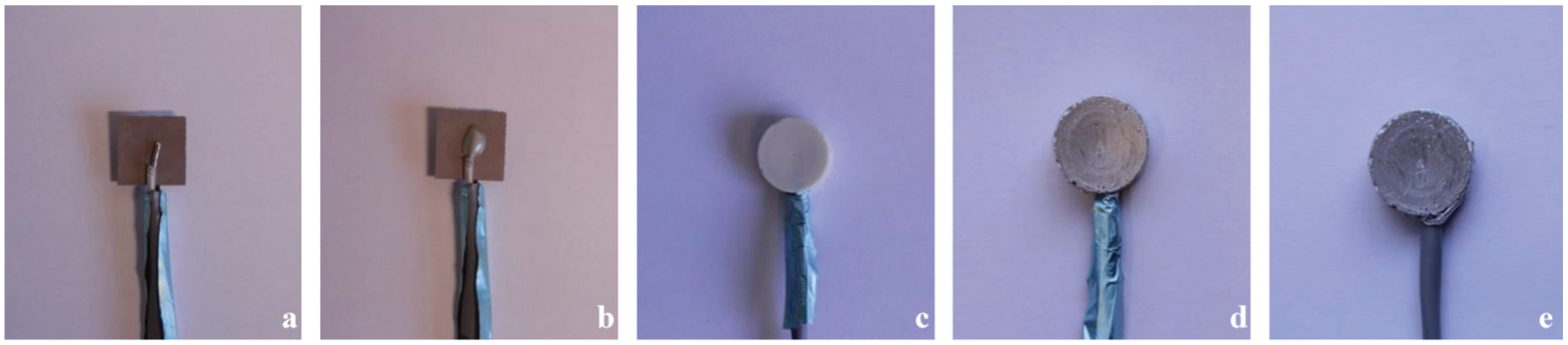
(a–e) SMAG transducer manufacturing process.
A high-voltage short rectangular wave (typically 800 V with a pulse width of 2.5 μs) is generated in a computer system and delivered to the SMAG transmitter. Then, a wide-band compressive wave (P-wave) is released that travels in all directions through concrete and is picked up by the available SMAG receiver(s). The received wave is filtered and pre-amplified before reaching a data acquisition (DAQ) 4 system in which the captured signal is properly post-processed in order to build a damage indicator representative of the damage evolution in the direct path between the transmitter and the receiver(s). The SMAG transducers consist of a low-cost flat piezoceramic lead zirconate titanate (PZT) patch (Figure 1(a)) of approximate size 12 mm × 12 mm × 0.2 mm. The electrical signals are transmitted to and from the transducer through electrical wires which are attached on both faces of the PZT patch (Figure 1(b)). Then, the patch is properly wrapped in a waterproof coating (Figure 1(c) and (d)), in order to avoid any possible capacitive coupling between the transducers. As the PZT patch is very fragile, the waterproof layer provides additional mechanical protection. A thin layer of conductive paint is finally applied to provide efficient electromagnetic shielding (Figure 1(e)). Consequently, the SMAG transducers can be placed in any place within the concrete structure without the use of coupling agent, thus facilitating the monitoring design.
Autonomous damage recovery by embedding into concrete encapsulated healing material
Imitating the healing mechanisms of natural organisms, materials science has developed autonomous reparation systems that aim to extend the service life of the constructions. The pioneering research of White et al. on encapsulated healing agent into polymers provides for the first time mechanical recovery of cracked area as soon as the capsules rupture and the healing agent is released filling the damaged plane. 1 A decade after, several healing systems (based on bacterial precipitation, agent microencapsulation, agent embedment into hollow tubes, autogenic healing, etc.) ensure regain of strength and stiffness under different loading conditions (thermal damage, micro-cracking, fatigue, corrosion, etc.) on constructive materials such as metals, asphalt, ceramics, polymeric, and cementitious composites. 5
In the case of concrete, wide cracking formed by extensive micro-cracks spread in the whole volume of structures requires great amount of healing material carried and released at the fractured area. Recently, at Magnel Laboratory of Ghent University, an innovative healing mechanism has been generated and it is able to heal concrete cracks up to 0.3 mm wide. 6 In fact, oblong hollow glass tubes are employed to carry a two-component expansive polyurethane-based healing agent (adhesive and accelerator). During casting, the tubular capsules are placed in couples at different locations into the material where damage is expected. The crack propagation transverses the capsules and breaks the brittle glass tubes concurrently leading to healing agent release. The two adhesive components fill the crack void and by completing the curing time (24 h) reset the consistency of concrete material. The efficiency of the aforementioned healing mechanism is being investigated under different loading conditions and using plethora of experimental techniques. 7
Up to now, previous research established a method to detect the tubular capsules breakage during the crack formation and identify the conditions under which healing activation occurs. 8 In parallel, the fracture response of concrete beam specimens tested under two-step pre-crack controlled bending tests (two cycles of loading: (a) crack formation–release of healing agent after capsules breakage and (b) crack re-formation after curing) indicates partial regain of strength and stiffness after healing. Acoustic (acoustic emission (AE)) and optical (digital image correlation) techniques monitor the crack evolution after healing.9,10 Although the significant findings regarding the fracture evolution after healing, sealing, and local consistency restoration of the crack are not recorded and thoroughly determined. The subsequent experimental setting purports to clarify that occurrence.
Description of the experimental set-up
Healing configuration
Plain concrete beams are prepared, cast into wooden moulds, and eventually fractured under three-point bending loading. The concrete mix proportions are given in Table 1. The specimen geometry and loading configuration are chosen to provide straightforward opening mode of fracture in concrete. Following the Rilem Technical Report FMC-50 regarding the fracture mechanisms in concrete, prismatic beams 840 mm long, 100 mm wide, and 100 mm high are prepared. 11 At the middle section of the beam, a 10-mm-high pre-notch is inserted by means of Teflon strip. As pin load occurs in the middle of the beam, pre-crack serves to activate fracture and guides the crack propagation up to the top of the specimen.
Concrete mix proportion.
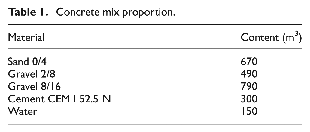
Before concrete casting, the susceptible-to-cracking region above the pre-crack is filled by the fragile glass tubes sizing 50 mm long and with inner diameter of 3 mm. The capsules, as shown in Figure 2, are placed in couples (attached on a low-stiffness plastic cord that sets their fixed position) and serve as carriers of the two-component polyurethane-based healing agent. The healing material is sealed and stored in the capsules until the moment when crack deformation causes the carriers’ rupture and the agent is released into the fractured plane. At that time, the two agent components come into contact and healing polymerization mechanism is activated. Essential restoration process is considered complete 24 h after cracking (curing period).
Casting process: embedded glass capsules and SMAG transducers are placed above and at both sides of the pre-cracked beam section, respectively.
Two bending test cycles are performed. An Instron electromechanical frame applies deflection at the middle section of the beam (span of bending is fixed at 800 mm) and a crack mouth opening displacement (CMOD) device is attached at both sides of the pre-notched groove to measure the crack opening. At first, the undamaged concrete beam is loaded under deflection control (displacement rate 0.04 mm/min) up to crack opening of 0.3 mm. At that stage, crack formation ruptures the capsules and agent release activates the healing process. After the 24 h curing period, the beams are retested under the same loading conditions. At that second stage, the recovery due to healing of the cracked region is evaluated by means of strength and stiffness regain.
SMAG transducer setting
SMAG transducer P-wave emission was efficiently applied in the past to detect crack initiation and propagation in several concrete test settings.12–14 In practice, the travelling time of the P-wave defines the mechanical condition of the material standing between the transmission and receiving locations. Considering as early arrival the direct wave contribution following the path between the transmitter and receiver SMAG transducers, the wave scattering due to material obstacles is eliminated and a linear relation between velocity and arrival time is established. Both travelling time and propagation velocity inclusively indicate the fracture evolution. Particularly, the decay or growth of several wave feature values is proportional to the degree of crack opening and closure. For instance, SMAG transducers’ high sensitivity may locally track the damage by means of wave energy and amplitude drop and prospectively detect autonomous sealing by healing material insertion that provides wave features recovery.
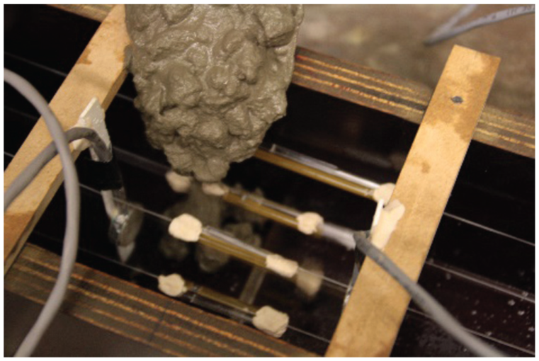
An overview of SMAG transducer monitoring system setting and the technical detailing are given in Figure 3. During testing, the emitted signals consequently form wavelengths short enough to be sensitive to fracture gaps or fillings and qualitatively determine the concrete health status by introducing a simple damage index (d.i.), based on the early part of the measured waves.
Concrete beam drawing: front/top and side view of SMAG configuration.
The d.i. is defined by the root mean square deviation (RMSD) value between two signals captured at the healthy stage (undamaged concrete in our case) and over testing (loading–healing curing–reloading in our case), respectively. The deviation between the damaged signal and the healthy one is divided by the integral of the square of the healthy signal contained in the time space which corresponds to the first half-period duration of the healthy signal. The equation providing the d.i. is given in Figure 4 where xo and xj stand for the signal amplitudes on the healthy stage and a moment j during loading, respectively; (tp − tn) stands for the duration of the first half-period. A schematic representation of d.i. variables is also given in Figure 4.
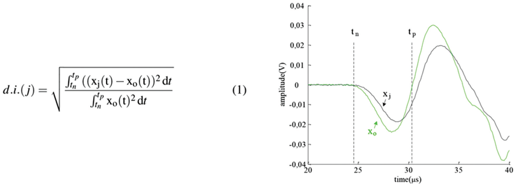
Damage index formula and early part signal drawing.
By definition, the d.i. is a scalar parameter and considers both the shift of the arrival time and the amplitude variations. Thus, any increase in the d.i. (values higher than 0) measured under bending deflection is indicative of crack formation and extension. The d.i. value saturates to 1 for relatively moderate levels of damage. On the other hand, any numerical restriction (value less than 1) states crack sealing and recovery (since the damage dispersion is confined).
Results
Bending cycles evaluating healing efficiency: cases of study
In Figure 5, the load–crack opening curves of several beams’ series obtained during both bending cycles are introduced. The continuous lining refers to the loading cycle of several series, and the dotted lines stand for the reloading cycle bending performance.
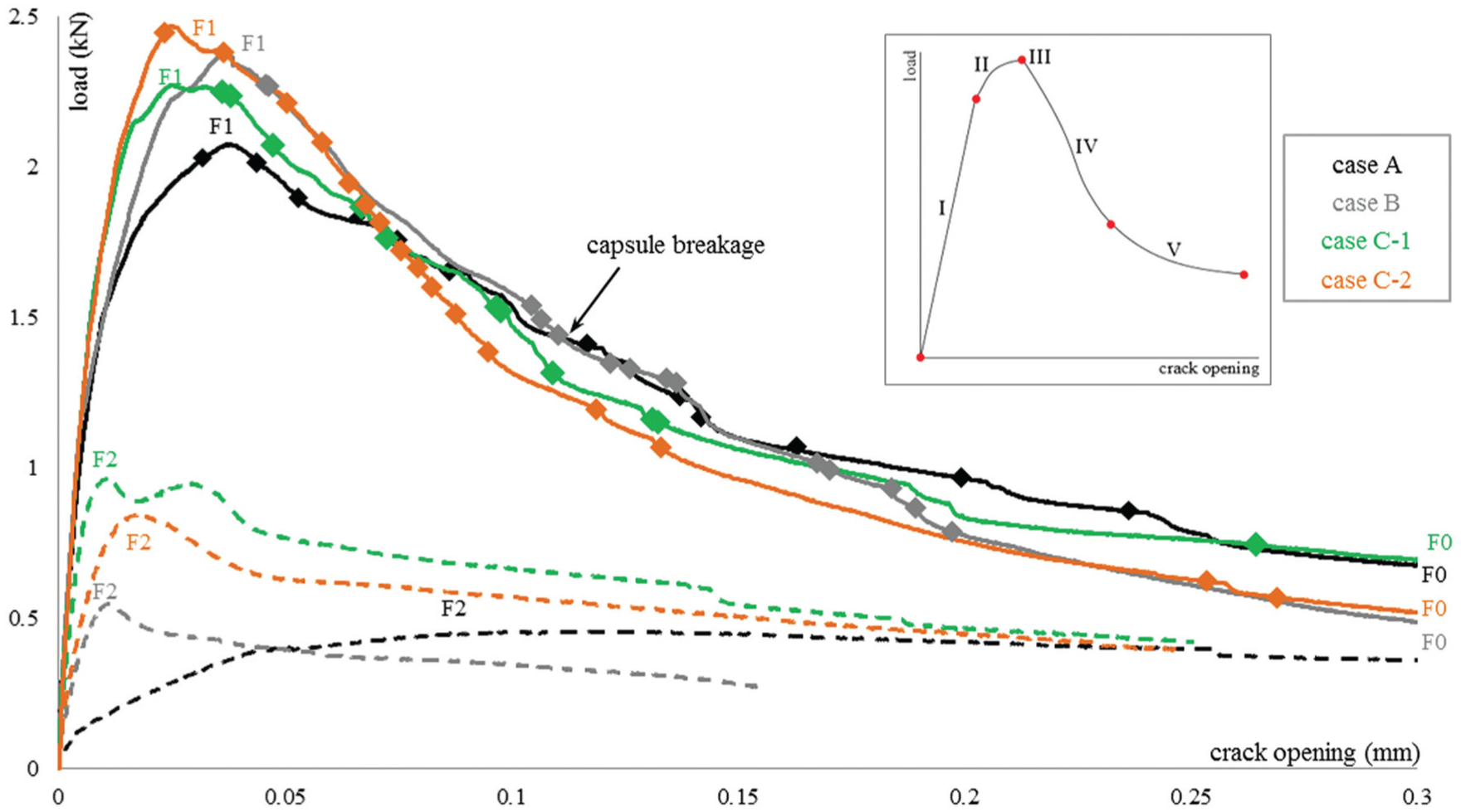
Two-cycle bending test: crack formation and reopening after healing agent curing. The moments of capsule breakage are given by marks. A drawing qualitatively indicating the cracking steps (I–V) is also provided.
The analysis concerning the healing performance requires a normalized capsule breakage pattern. AE contributes to that direction by detecting the sound activity originating from the glass tube rupture. As recently presented in a previous research, 8 AE energy-based analysis confirms the healing activation by capsule breakage as soon as crack forms and propagates across the concrete material. For the sake of completeness, the loading moments at which capsule breakage occurred are subsequently presented in Figure 5. It is observed that large number of capsule breakage events (affirming that all the embedded capsules ruptured) appeared during the crack formation and propagation stage of loading for all the specimens concerned in this study. Below, having proven the healing agent stimulation, the sealing and recovery performance is analytically investigated by the ultrasonic pulse velocity technique using embedded SMAGs.
Considering the healing performance, the concrete material tested is classified into three series presented in Figure 5. The modified features in each case are the healing agent characteristics/distribution and the height level of SMAG transducers. They are discussed below in detail.
Case A: Reference-no healing activity
A concrete beam is prepared and four couples of empty glass capsules are embedded according to the casting instructions above. Despite the absence of healing material that series aims to contribute as a reference measurement (healing activity is not expected). In parallel, both the main sources of fracture process (concrete cracking and capsule rupture) stand even in that case to ensure same loading conditions at all testing series. One pair of SMAG transducers is fixed at a height of 35 mm from the bottom of the beam.
Case B: Partial damage recovery due to healing
A concrete beam is cast and four couples of glass capsules, filled by limited amount of inefficient healing agent, are placed into concrete. In this case, healing is activated and limited agent is released covering partly the damaged plane, but still mechanical recovery is not achieved. A pair of SMAG transducers facing the crack is located 35 mm above the bottom of the beam.
Case C: Healing performance monitored at different crack heights
Two concrete beams are cast and eight couples of glass capsules, filled by sufficient amount of healing agent, are embedded. The material setting is designed to provide sufficient damage recovery of the crack formed under bending. In the first beam, a pair of SMAG transducers is placed at a height of 35 mm from the bottom of the beam (case C-1) and in the second two pairs of SMAG transducers are embedded (case C-2) at different heights 20 and 50 mm from the bottom of the beam. During bending test, one of the SMAG transducers, located closer to the bottom of the beam, is chosen to continuously contribute as transmitter and the two SMAGs, standing at the other side of the pre-notched groove, receive the signal propagated through the cracked plane. With the aforementioned transducers’ placement, the sealing of the crack and the mechanical performance regain is aimed to be monitored at different heights across the crack. A detailed drawing of the C-2 case, giving schematically a representative experimental setting, is shown in Figure 4.
Strength and stiffness regain
In Figure 5, the loading–crack opening graphs as obtained for the different cases analysed under two cycles of three-point bending tests are presented. The load and stiffness recovery at the second loading cycle (following the healing activation and curing of agent) are well established as indicators of healing efficiency. 6 With that approach, the ultimate load (both at loading and reloading stages) and the initial compliance are chosen to quantitatively evaluate the healing response in Table 2.
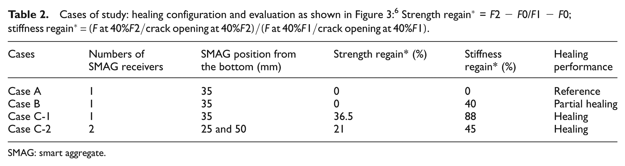
SMAG: smart aggregate.
As shown at the two-cycle bending curves, during reloading, the damaged material of case A cannot withstand bending load greater than the load at the end of the first cycle, pointing the absence of any crack resistance. The reference material, as expected since healing is not considered, lacks the initial elastic response of quasi-brittle concrete nature providing no evidence of stiffness recovery. Regarding the reloading performance of case B beam, partial stiffness regain is observed. In comparison to case A, the initial linear inclination is recovered up to 40% of the loading cycle compliance. Despite this, strength regain is not achieved since the peak load at the reloading cycle was not able to surpass the load at the end of the loading bending cycle. The limited amount of agent and the insufficient bonding efficiency of the healing material are confirmed. Noticeable mechanical recovery is obtained in case C, in which strength and stiffness restore is measured up to 21%–36.5% and 45%−88% for case C-2 and C-1, respectively. As shown in Figure 5, the initial compliance is well reset after healing agent curing and the loading capacity obtained at the second cycle overcome the final load of the loading bending cycle for both beams.
Regrettably, the insufficient recovery of opened crack cannot be shown in the global overview of the bending response. The only evidence of healing activation is the location of capsule breakages by means of AE energy analysis, as introduced in previous paragraph. According to the marks in Figure 5, for all the cases of the analysis, the capsules break releasing the healing agent at several post-peak loading stages. The effect on cracking response and the contribution of the released healing material to the mechanical performance is further investigated in detail using the ultrasonic pulse velocity technique by embedded SMAG transducers.
Evolution of wave velocity at both loading stages
The travelling time of compressional P-wave into concrete over a known distance contributes further on that research since it provides the mechanical condition of the element.15,16 As introduced, the fixed location of SMAG transducers ensures determinate distance between the points of wave transmission and reception. The emergence of a macro-crack decreases significantly the wave propagation time since the released compressive wave is scattered and dispersed at the crack front plane before reaching the received transducer. It should be pointed that the bending fracture intensely affects the time delay relatively to microvoids and aggregates glass tubes embedded into the concrete specimens. Considering the analysed concrete beams, wave velocity gradual decline is observed during bending in all three cases. At the loading cycle, the travelling time remains constant until the crack formation providing a stable wave velocity presented for each case on the first column in Figure 6. Beyond crack release load, the time delay almost linearly increases until the end of bending. Consequently, as the crack propagates, the wave velocity is significantly reduced towards the values given for each beam series on the second columns in Figure 6. At the bottom of Figure 6, plots of the velocity evolution during loading/reloading are given for the sake of completeness.
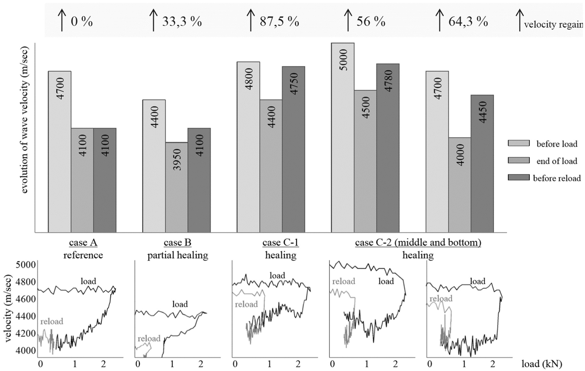
Wave velocity evolution at both cycles of loading (case C-2 results are given for both SMAG transducers receivers standing 25 and 50 mm above the bottom of the beam, respectively) where
The wave velocity deterioration is well-studied in the past and linked to the crack fracture in concrete.13,17,18 In reverse, diffuse ultrasound on autogenous healed concrete correlates the crack width reduction after healing to the arrival time of the signal maximum energy. 19 The novelty of this study is the monitoring of fracture recovery due to autonomous sealing by means of wave velocity reset. In detail, the third columns in Figure 6 present the wave velocity as measured at the beginning of the reloading cycle. As expected, in the case of reference material the velocity is measured at the same values as previously (velocity recovery at 0%). On the contrary, the wave velocity is slightly regained in the case of the beam with partial stiffness recovery by insufficient healing. As shown in case B of Figure 6, the velocity measured after agent curing is recovered by 33.3%.
Furthermore, the efficient healing in case C as obtained at the loading response, discussed at the previous paragraph, is evident even by wave velocity measurements. The released healing agent fills the crack and covers the opened volume restricting the distortion effects on the early part of the propagated wave. The significantly shorter travelling time leads to wave velocity rest up to 87.5% after damage in case C-1. It is highlighted that even if the crack is fully filled, the velocity is not expected to be totally recovered to the initial value due to stiffness discrepancies between the concrete matrix and the healing agent as previously shown.20,21 The great velocity recovery of case C-1 is correlated to the high stiffness restoration (88%) as obtained on the load response analysis (see Figure 5).
In case C-2, the allocation of the released healing agent at different heights of the beam is detected. More specifically, a slight difference in the wave velocity recovery might indicate the cracked regions in which healing performed better. However, definite finding cannot arise from the wave arrival time analysis. Further focus at several wave features (e.g. amplitude of received signal) and the crucial early part of the arrived signal may provide the state of fracture and efficiency of crack healing.
Evolution of the received signal amplitude at both loading stages
The bending deflection rate is chosen to comprehensively display the quasi-brittle cracking propagation and, simultaneously, to enable the ultrasonic pulse velocity technique using embedded SMAGs to continually track the progressive damage. The gradual crack opening/closure/reopening is captured as the information carried at the early part of the signal that contains the contribution of a direct wave between the SMAG transmitter and the SMAG receiver. The received signal amplitude evolution of the direct waveform is derived for the following vital cracking fracture steps (schematically represented by the drawing in Figure 5):
Step I: the initial loading response is linear as elastic deformation of the beam occurs.
Step II: the non-linear loading response indicates micro-cracking fracture on concrete. At critical load, localized damage is introduced and fracture zone around the pre-notch forms. 22
Step III: reaching the concrete strength, load drops and crack releases from the pre-notch as strain softening plasticity initiates.
Step IV: the crack propagates further up to the top of the beam. The loading drops almost linearly suspended by limited crack arrest ahead of the glass capsules.
Step V: the second part of the bilinear post-peak load drop occurs as the resistance to damage ceases and the crack gets wider.
In Figure 7, a series of signal windows present the early part of the received signal as monitored at respective cracking steps (I–V) during both bending cycles for the three cases under study. Furthermore, in Figure 8, the information derived from the signal window above is normalized and associated with the load and crack opening evolution. For the sake of completeness, a schematic overview of wave velocity, concrete strength and stiffness regain for all three cases is shown as well.
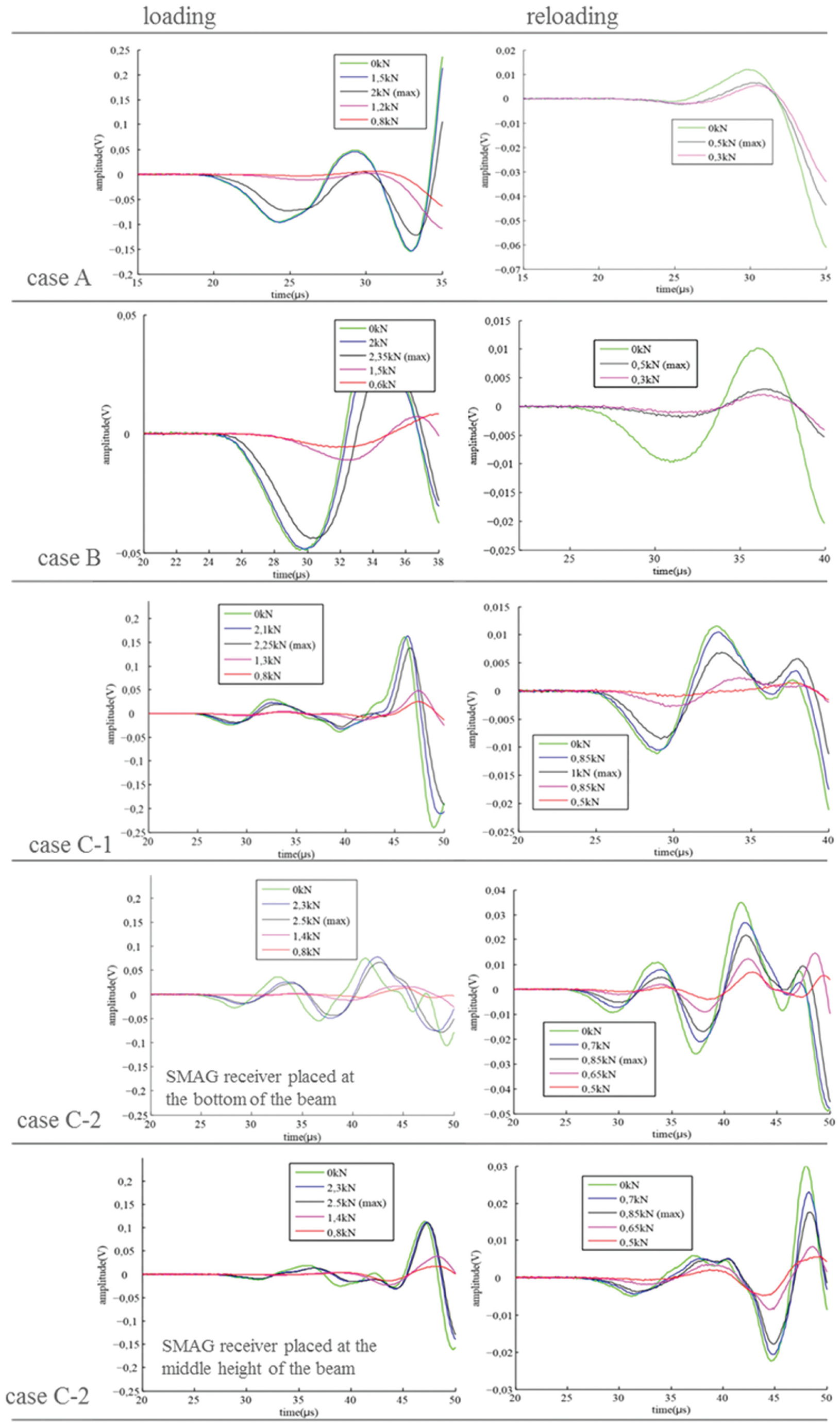
Early part of wave as received at different stages of loading/reloading cycles.
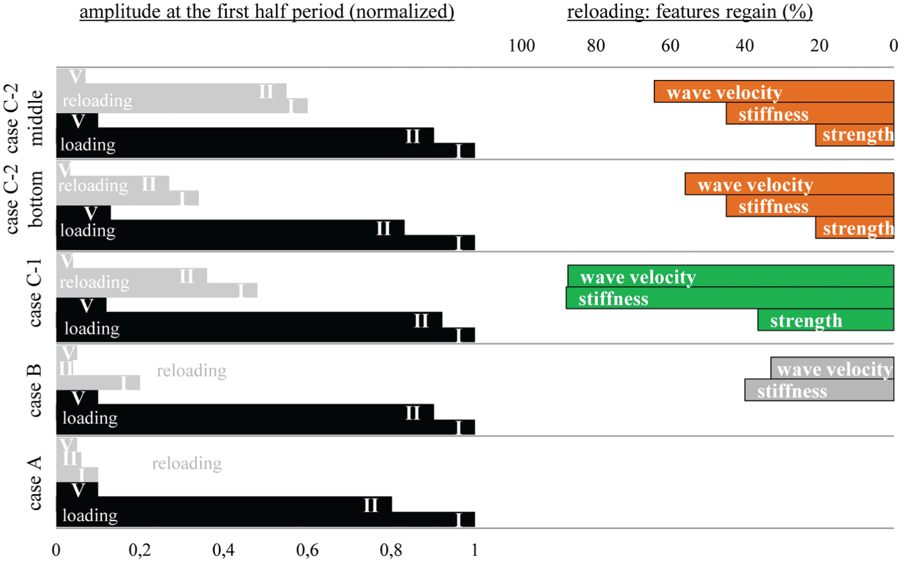
Early half-period amplitude evolution during both cycles of loading correlated to the mechanical recovery.
As expected, the crack initially forms controlled by the same fracture mechanisms throughout the several beams, thus the loading cycle signal response is nearly identically repeated. The first period amplitude received at the beginning of loading is progressively effeminate as crack widens. The amplitude range differentiates as soon as step II of loading occurs since concrete micro-cracking introduces attenuation and distortion effects. The degradation dominates as the strength of concrete is reached (step III) and the attenuation affects the early part of the overall signal shape. At the end of loading cycle, the signal form is significantly modified and the amplitude is considerably decreased by a factor of 10 (steps IV and V). The accomplished amplitude measured as cracking indicates the damage state before healing insertion. Therefore, cracking filling is confirmed since after curing of the released agent the signal amplitude is successfully recovered.
It is not so in the case of reference beam (case A) where the signal recorded at the beginning of reloading cycle obtains an amplitude value equal to the loading final one. Furthermore, as shown in Figure 7, the signal strength remains immutable during reloading cycle evidencing the lack of mechanism that may provide resistance to crack reopening. On the contrary, a limited amplitude recovery is monitored in case B of the analysis, in which the signal amplitude at beginning of reloading shows an increase of more than 10% relatively to the damaged state at the end of loading. The amplitude partial regain is correlated to the stiffness restoration, but the absence of strength recovery is evident by the invariable wave shape throughout reloading test (Figure 7).
Both amplitude initial restore and signal shape variation during bending are monitored in case C reloading tests. As demonstrated in the early part of the signals of Figure 7, the amplitude value is well regained after agent curing and sealing of the damaged concrete zone. Numerically, the signal amplitude is reverted up to 50% relative to the loading bending cycle. Furthermore, restored resistance to damage is displayed by the waveform shape spread as crack reopens. It is observed, similar to the loading case damage propagation, that the signal loses its initial magnitude (degradation) and morphology (widening and flattening) as crack traverses the healed region.
Respectively, in Figure 8, the signal amplitude as obtained at the beginning of the loading cycle (step I of analysis) reflects the healthiest conditions under investigation and based on that an amplitude normalization calculated at several loading steps is presented. For that reason, the normalized value chosen at the start of loading is equal to unity and after crack propagation the normalized amplitude is decreased up to 0.1 at step V of loading cycle (similar deterioration for all the beams). On the other hand, amplitude recovery is well noted as soon as healing agent curing occurs. As shown in Figure 8, the amplitude is increased up to 60% in case C-2 as measured by the SMAG transducer standing in the middle height of the beam. The least amplitude restoration is calculated for case B of partial healing. Finally, a correlation between the amplitude regain and the stiffness and P-wave velocity restore is observed. It is shown that the waveform amplitude as measured before reloading can provide a good indicator of wave velocity and stiffness recovery due to healing. As expected, the amplitude at the early part of the signal is sensitive to the concrete rigidity and damage existence.
Furthermore, the amplitude normalization (based on the healthy status) applied once again at step II of crack formation during both cycles of bending correlates to the absence of strength regain as measured at the loading–crack opening curves. As anticipated, the mechanical recovery is well captured in case C amplitude observations. On the other hand, it is worth pointing the lack of amplitude value recovery in case B of partial healing. At the bending step of crack reopening, the amplitude deteriorates further after initial damage.
Evaluation of d.i. at both loading stages
On an integrated approach, the damage evolution, calculated by the normalized d.i., plotted as a function of the applied load aims to provide a comprehensive view of cracking process during testing. The d.i. distribution is plotted in Figure 9 for the several healing cases.
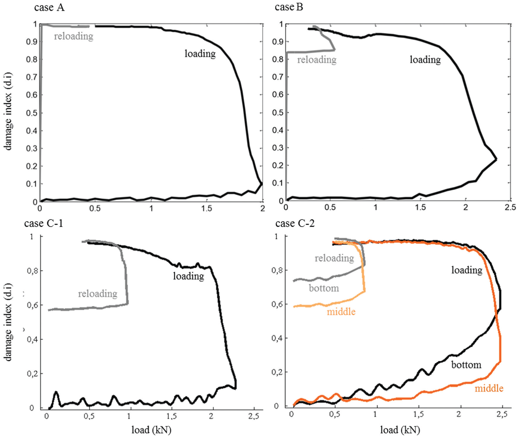
Damage index of loading and reloading cycles as assessed for all three cases of study.
At loading cycle, d.i. evolves similarly for all three cases recording the five steps of bending fracture. The initial elastic response of concrete provides almost 0 d.i. values (step I of fracture). The deviation from 0, associated with certain level of noise in the signal, is minimal and can be negligible. The introduction of micro-cracks and fracture zone formation differentiates the d.i. from 0 values as step II of cracking occurs up to the strength of concrete (step III). As crack propagates till the top of the beam (step IV), the d.i. value increases significantly reaching the unitary level and forming a plateau as crack widens (step V). At the end of loading cycle, the great d.i. indicates that the opening of crack disturbs (almost prevents) the wave propagation and scatters the signal transmitted.
In case C-2, there is a great differentiation regarding the initiating point of the first-cycle crack fracture. As shown in Figure 9, the d.i. appears and deviates from 0 earlier as calculated at the bottom of the beam (SMAG receiver stands at a height of 25 mm from the bottom of the beam) than the one measured at a higher level of the beam (the second SMAG receiver transducer is fixed 50 mm above the specimen). Therefore, the d.i. is able to promptly detect crack formation at the pre-notched region of the beam. Actually, the d.i. deviation from 0 as measured at the lower level of the beam appears earlier than the deviation from linearity in the loading graphs of Figure 5. It is shown that the d.i. is sensitive to the preliminary manifestation of cracking and detects micro-cracking initial damage.
At reloading cycle, the d.i. evolution reveals the efficiency of healing process. Once again, the reference case A shows no damage recovery by giving unitary d.i. values during the whole reloading test. Limited reduction of d.i. value is obtained in case B of the analysis, in which at the beginning of reloading cycle, the normalized d.i. is equal to 0.85. However, significant decrease in d.i. after healing agent curing occurs in cases C-1 and C-2 as the indicator initial value is measured less than 0.6 for both cases. Furthermore, in case C-2, it is shown that the crack sealing by means of released healing agent can perform better at the damaged area with limited crack opening at the middle height of the beam compared to partial d.i. regain (more than 0.7) obtained at the bottom of the beam. It is concluded that the widely opened areas of the crack cannot be easily filled by healing material and sufficiently restore their mechanical characteristics (both stiffness and strength). For the first time, a testing setting yields information on crucial areas of the healing material, by monitoring the wave propagation through damage in different locations.
Discussion – early part sensitivity to damage
Ultrasonic monitoring of damage evolution by SMAG transducers emerges as a key tool in the study of healing efficiency in concrete. The wave velocity of the transmitted signal as received by SMAG transducers at the healthy and healing state indicates mechanical recovery providing a preliminary exploration on the potentials of the technique.
The signal deterioration at the damaged state should be cautiously considered since wide crack formation leads to amplitude decrease up to the noise levels and thus arrival time misperceptions. Instead, the d.i. continually merges the arrival time and amplitude information providing an integrated monitoring of crack evolution during testing. By calculating the modification of the early part of the signal received as crack forms, opens and reopens after healing, the d.i. seems to be very sensitive to any cracking variation. The shape and magnitude of the received signal attain significant recovery as soon as sealing of the damaged area has occurred. For instance, in Figure 10, the early part of the two signals transmitted through a damaged and a healing recovered area as received by an SMAG transducer are placed together. The amplitude of the signal captured after released healing agent curing is considerably greater than the one captured before healing activation. In parallel, the overall shape of the signal early part resets its initial healthy density compared to the spread signal captured at the damaged state.
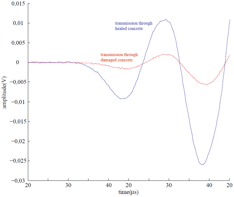
Detail of early part of signal indicative of sealing recovery.
Conclusion
Until today, ultrasonic pulse velocity technique using SMAGs seems to be a practical, cheap and efficient technique to assess concrete curing conditions 23 and damage that overcomes the experimental limitations of traditional ultrasonic techniques. For the first time, SMAG transducer monitoring is successfully applied to evaluate the inverse fracture process: crack closure, sealing and recovery of concrete cracks up to 0.3 mm wide. The controlled pre-cracked three-point bending set-up forms damage propagating across the height of a small-size beam. SMAG transducers continuously monitor the crack evolution and the several signal features (P-wave velocity, waveform early part amplitude range, signal shape morphology) provide a respective damage indicator. By placing pairs of SMAG receiver–transmitter transducers at different height levels on both sides of the crack plane, the areas where healing agent is well released are detected.
Evaluating the test configuration, it should be pointed that the crack control by pre-cracking certainly serves to the transducers positioning close to the crack propagation zone. In cases of prospective more realistic concrete tests, where multiple, deep and extensive cracking is expected or the cracks’ location and interaction are not known, SMAG monitoring transducers should be sophistically and strategically placed.
Another topic of discussion is the attenuation effect on the propagated wave. In this case, attenuation does not prevent wave transmission and reception by SMAG. In case of longer distances between the transducers, the excessive attenuation could be tackled by adjusting the voltage input at the pulser.
With respect to noise, clear view of the noise involved cannot be derived. In future, one should consider the complex nature of concrete and the multi-scale damage phenomena occurred before establishing a threshold above which crack dominates and noise effect does not affect damage detection.
Footnotes
Acknowledgements
The research described in this article has been performed in the frame of the SIM program on Engineered Self-Healing Materials (SHE).
Funding
This study received financial support from Strategic Initiative Materials Flanders (SIM) and Fonds de la Recherche Scientifique (FNRS).