
Abstract
The study examines the use of hybrid carbon-based textile-reinforced concrete elements with self-sensing capabilities to quantitatively detect wetting events within cracked zones. The self-sensory structural element combines the advantages of AR-glass and carbon-based textile-reinforced concrete for thin-walled structural elements with those stemming from the electrical properties of reinforced carbon rovings. The article investigates the sensitivity of sensory carbon rovings to distinguish between the magnitudes of various wetting events, which is associated with the severity of the cracking, according to two electrical setups (DC and AC circuits). The sensing concept takes advantage of the continuous configuration of the carbon rovings, which enables direct connection of the roving ends to the data acquisition system, and of the manufacturing process that two carbon rovings are placed adjacent to one another. Therefore, it is assumed that wetting events electrically short-circuit the two adjacent rovings. The sensitivity of the two electrical setups is experimentally investigated and performed on a couple of bared carbon rovings and on a cracked textile-reinforced concrete beam. Test results demonstrate the sensitivity of the sensing capabilities of the carbon rovings to detect and distinguish between the magnitudes of the wetting events and consequently the severity of the cracking.
Keywords
Introduction
Water distribution is one of the most important issues in human society. The growth of the global population increases the need for innovative technologies to manage water distribution. Modern and advanced countries strive to achieve well-maintained water distribution systems that supply water from its source to the points of usage. One of the main challenges in this field is to develop modern, sustainable, and intelligent water distribution systems that enable monitoring of the structural and functional state of the system and offer early detection of damage, water infiltration, and leakage. In that sense, alkali-resistant (AR)-glass and carbon-based textile-reinforced concrete (TRC) technology offers a preferable alternative to the conventional steel reinforced concrete building materials. Compared with traditional steel reinforcement, it is lighter, stronger, more durable, and less affected by corrosion. Moreover, by taking into consideration the conductivity of the carbon rovings, which are an integrated part of the main reinforcement textile, a sustainable hybrid TRC structural element with integrated sensing capabilities is achieved.
Currently, in order to monitor an RC water distribution system, a monitoring system, which is either external or internal, depending on the installation possibilities in the structure, is usually installed independently of the structural system. In the case of external monitoring systems, sensors are mounted on the structure and can be installed on existing and old structural elements. Such systems are usually based on indirect measures of water penetration, such as temperature and pressure changes.1,2 Although these methods can be implemented successfully, external monitoring systems are usually sensitive to environmental conditions and may separate from the structural element during its service life. Internal monitoring systems can overcome these problems since they are implemented within the structure during the production of the element. Capadevila et al. 3 offered embedded passive radio-frequency identification tags to identify water infiltration. Liu et al. 4 used piezo ceramic-based smart aggregates to estimate the depth of water infiltration in concrete, and Zou et al. 5 monitored the travel time of harmonic stress waves as indication of seepage depth in concrete structures. However, the clear distinction between the structural and sensory systems of the monitoring techniques presented above necessitates an additional effort so as to couple the two systems. The accommodation in the load-bearing element and the potential degradation of its load-bearing capacities are further drawbacks of such methods.
A sensing system that is integrated into the structural system offers a preferable alternative to traditional sensing systems. Such a system is based on combining high-performance materials and structural systems with integrated monitoring systems. Thus, instead of joining two separate systems (i.e. the structural system and the monitoring system) in one element, a single, multifunctional physical element addresses the two tasks. In that sense, AR-glass and carbon-based textile-reinforced concrete technology, which employs fine-grained high-strength concrete with carbon and AR-glass fibers–based textile reinforcement, is a preferable candidate. The textile mesh has high load-bearing capacities and it is highly resistant to corrosion. The sensory elements based on using the same array of continuous carbon rovings for the reinforcement are required for the load-resisting system and, at the same time, as the component providing the structure with the self-sensory feature. In this configuration, some carbon rovings replace glass fiber rovings and they are embedded in the glass textile net as an integrated part of the production of the textile. The implementation of the sensory textile in the concrete element is a straightforward act and it is no different than using standard textile reinforcement. The self-sensory capacity is gained by detecting changes in the electrical properties of the continuous carbon rovings, which are an integrated part of the reinforcement system. Accordingly, cost and labor inputs needed for converting the component into a sensory one are almost eliminated.
The concept of the smart textile reinforcement has been mainly implemented for structural health monitoring of strain and damage sensing of carbon-based TRC beams under mechanical loading.6-9 Goldfeld et al.10,11 presented the feasibility of the concept on structural TRC beam level and showed that electrical resistance measured from conductive rovings, made of carbon or stainless steel fibers, can follow the structural response. It was also presented by Goldfeld et al. 12 that the smart carbon rovings–based reinforcement can sense the structural response of TRC structures along the entire range of loading process, from very early stages of loading and up to progressive failure mechanism, where traditional sensing devices usually failed to produce meaningful information. All the above studies used DC electrical setup by connecting the conductive rovings to Wheatstone bridge electrical configuration. The assumption was that straining and environmental changes lead to resistance change that can be measured by such an electrical configuration.
The sensory capabilities of continuous yarns made of conductive fibers to sense wetting events and infiltration of water have been mainly investigated for stainless steel yarns. Quadflieg et al. 13 and Goldfeld et al.10,14 investigated the ability of stainless steel yarns embedded in the textile as part of the production process, to sense wetting events. Goldfeld et al. 14 investigated several electrical schemes related to several sensing concepts. They showed that electrical short-circuiting of couple of yarns due to wetting can lead to sensitive and stable electrical readings. In the case of stainless steel yarns, however, they do not add stiffness to the textile and, as a result, to the TRC structure and serve mainly as a sensory agent. On the other hand, continuous carbon rovings, which have a preferable stiffness, can be used both for structural reinforcement and as a sensory agent. Goldfeld et al.6,11 presented a preliminary investigation for the detection of wetting events by carbon-based TRC structures. They proved the feasibility of using carbon rovings as the sensory system for wetting events. However, they assumed that the electrical readings reflect a change in carbon roving conductivity due to water penetration into the capillary space within the carbon filaments. Recently, Goldfeld and Perry 15 investigated this assumption and found that wetting a single-carbon roving mainly effects the electrical inductance of the roving, and the electrical readings observed by Goldfeld et al.6,10,11 are due to electrical short-circuiting between the two conductive rovings that were connected to two Wheatstone bridge configurations. Goldfeld and Perry 15 characterized the electrical signal obtained by two sensing concepts based on AC electrical circuits: conductivity change of a single-carbon roving and electrical short-circuiting two adjacent carbon rovings due to wetting. They also found that pronounced and stable electrical readings are obtained by electrical short-circuiting two adjacent carbon rovings. Therefore, in order to investigate the sensitivity of the electrical readings to sense the magnitude of the infiltration of water, this sensing concept is adopted in this study.
The goal of this study is to take this concept one step further and to investigate the sensitivity of carbon-based TRC structural elements to quantitatively detect the magnitude of wetting and infiltration of water into cracked zones along the TRC structure. Moreover, change in the electrical signal is conditioned by two events: the cracking of the concrete and the wetting of the element. If one is known, the other can be monitored, meaning that if it is known that the concrete is cracked, the exposure of internal carbon rovings to water can be monitored as an indicator for wetting. On the other hand, if it is known that the element is exposed to water (e.g. in a TRC pipe for water delivery), a positive reading can be used as an indicator for cracking. Therefore, this study aims to provide effective means for the structural and functional monitoring.
The study adopts the concept that wetting events electrically short-circuit two adjacent rovings. The sensitivity of the electrical reading is investigated using two electrical setups. The first electrical setup is by connecting rovings to two Wheatstone bridge configurations. Wheatstone bridge configuration has been implemented successfully by Goldfeld et al.7,9,11,12 for strain and structural damage sensing of carbon-based TRC elements; therefore, it is advantageous to use the same electrical setup to sense both straining and wetting events. The second electrical setup is based on an AC circuit that, compared to the first electrical setup (based on a DC circuit), has the ability to measure the impedance and its phase. These are two electrical quantities that characterize the electrical signal.
The investigation is mainly experimental and is performed on two levels. On the first level, bared carbon rovings are tested in “sterile” environments, and then on the second level, they are tested within a cracked beam.
The article is divided into three main parts. First, the methods and materials involved in the production of the TRC elements, including beam loading and crack formation, are presented. This part also includes a description of the mold designed for the first-level investigation (bared carbon rovings and a body of water). Then, the two electrical setups are presented in detail. The article closes with a discussion and the main conclusions.
Methods and materials
The sensory abilities of carbon rovings to quantitatively detect and distinguish between different magnitudes of wetting events and infiltration of water at cracked zones in TRC elements are studied experimentally. The study is based on the concept that two adjacent carbon rovings undergo electrical short-circuiting due to water penetration. The investigation is performed on two levels: the component level (bared rovings) and the structural element level (textile-reinforced concrete beam). The sensitivity of the carbon rovings to sense wetting events on the component level is investigated using a special mold that is designed to specify the wetted zone along the rovings. To make the shift from the component level to the structural element level, a carbon-based TRC beam specimen is designed, casted, loaded, and tested. The production and properties of the textile, the special mold, the construction of the TRC beam specimen, the loading process, and the formation of cracks are outlined in the following sections.
Glass/carbon textile
The sensory textile is based on carbon filament roving and rovings made of AR-glass fibers. The glass rovings form the main reinforcement platform, while the carbon rovings, which are also part of the main reinforcement system, serve as the sensory agent. Table 1 presents the material properties of the glass and carbon rovings.
Material properties of the glass and carbon rovings.
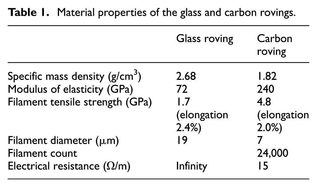
The reinforcing textile is a warp-knitted grid structure with a mesh size of 7–8 mm. The carbon rovings are inserted during the warp-knitting process by replacing some of the glass rovings. The stitch type of the warp knit is pillar. The weft direction consists only of AR-glass rovings, and so the configuration, which limits the sensing capability to one direction only, prevents potential electrical linking between one longitudinal carbon roving and the other.
The textile layout and production processes are based on standard textile manufacturing techniques, equipment, and materials. The production of the AR-glass/carbon textile uses a conventional process that does not involve any modification in terms of tribology or tension control of the rovings. This is achieved by selecting fiber materials that are suitable to be used in standard process and demonstrates that the production of the sensory textile does not involve cost-intensive modifications. Hence, the only modification is the replacement of some glass rovings with carbon rovings.
The electrical integration of carbon fiber rovings into the data acquisition (DAQ) system uses non-insulated wire ferrules that are threaded through the carbon rovings and crimped using crimping tools. Connectors are installed at the ends of each carbon roving and embedded into the concrete (or the mold) during the beam casting process. The electrical wires protrude from the concrete beam (or the mold) and later are connected to the DAQ according to the chosen electrical configuration. Note that the sensory carbon roving reinforcements have no special treatments along its active length and the connections are made only at its ends. This electrical connection allows stable and repeatable integration of the carbon rovings into the electrical circuits.
Component level—bared carbon rovings
The investigation on the bared rovings level focuses on the influence of water on the electrical scheme and is studied using a model apparatus that includes only carbon rovings and a body of water. This case does not include a concrete component. Two carbon rovings are installed in an isolated mold with a square, 20 × 20 mm2“window” (see Figure 1). The rovings and electrical connectors (at the ends of the rovings) are placed in special slots within the mold, tensed slightly, and covered with isolating clay to avoid water penetration. The distance between the rovings is specified according to the textile mesh size and, in this case, equals 8 mm. The electrical wires are protruded from the mold so that only a specified prescribed length (up to 20 mm) of the rovings is exposed to water. The wetting process is performed by immersing the window, within the mold, into a water bath. The process is controlled by a linear stage (Zaber T-LSM025) that is connected to the mold. The wetting distance along the rovings is specified by a prescribed wetting profile with an accuracy of up to 8-μm pick-to-pick (which is the accuracy of the linear stage).
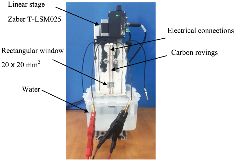
Mold used for the component-level tests (bared carbon rovings).
Structural level—TRC beam specimen
A concrete beam specimen (300 × 70 × 20 mm3), reinforced with two layers of sensory carbon-based textile, was designed and casted. The two layers are located 4 mm from the upper and lower faces of the beam. Each textile layer includes six longitudinal (0°) glass fiber rovings and three longitudinal carbon rovings. The transverse (90°) rovings are all made of glass fibers.
The number and location of the textile layers were determined in order to answer both the reinforcing and the sensory requirements. According to the loading scheme, four points bending, the two layers were located along the tensioned zone of the beam (lower face) and along the compressed zone of the beam (upper face). Both layers were located 4 mm from both faces. The 4-mm concrete cover was determined to enable good bonding layer between the rovings and the concrete. The common concrete cover in such loading configuration is about 3–10 mm (see, for example, the works by Holler et al. 16 and Williams Portal et al. 17 ). Lower concrete cover and additional textile layers will increase the effective fiber fraction, which eventually improves the ductility of the system and allows multiple distributed cracks. This is the desired design state in TRC structures. 18 On the other hand, higher concrete cover in the tensioned zone will lead to reduction in the load-carrying capacity of the structure due to the formation of few macro-cracks. Since this study aims to investigate the sensitivity of the smart sensory system to various width of cracks and as a result to various magnitudes of wetting events, the chosen geometric configuration was designed to capture various width of cracks both micro-cracks and macro-cracks.
Following Goldfeld et al., 12 the beam is casted in a special mold designed to maintain a preliminary low level of pre-tensioning of both layers of sensory textile in all four directions. This procedure aims to keep the textile layers in place during casting, to allow smooth flow of the concrete (grout) mix and to prevent segregation. Figure 2(a) shows the textile in the mold before casting. Figure 2(b) depicts the general layout of the beam, including the two textile layers with electrical connectors. Figure 2(b) also presents a cross section of the beam and the geometrical details of the two layers of textile reinforcement.
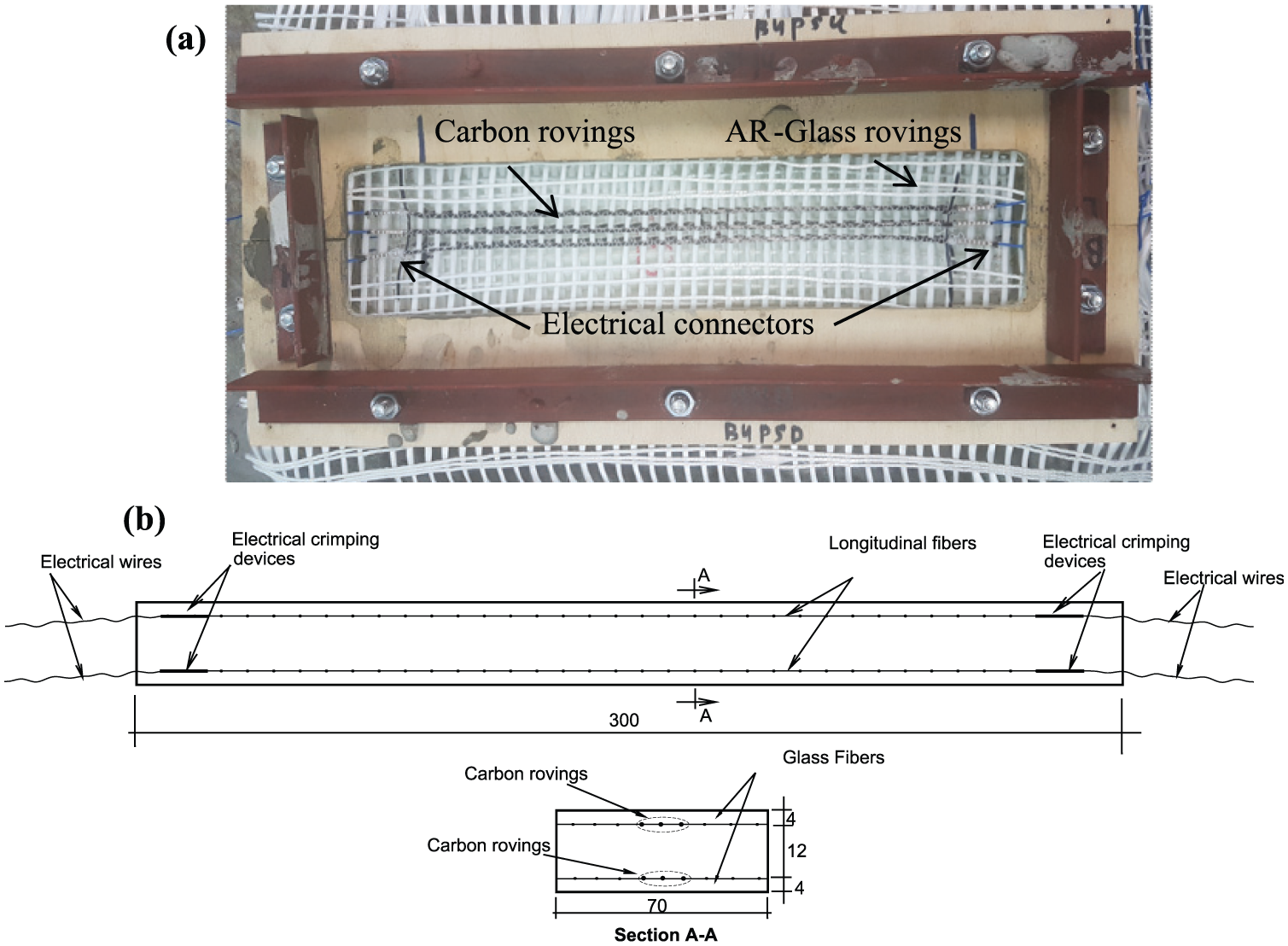
TRC beam: (a) the textile within the mold before casting the concrete and (b) schematic drawing of the beam (dimensions in mm).
The beam was casted using a commercial grout mixture (SikaGrout-214) prepared according to manufacturer’s instructions using 3.125 L water per 25 kg dry material. The beam was covered with polymer sheets and cured at room temperature for 48 h.
Mechanical loading of the TRC specimen
The main goal of the study is to investigate the sensitivity of carbon rovings to sense potential infiltration of water within cracked zones along TRC elements. To explore the capabilities of the proposed electrical setups to distinguish the crack severity and, as a result, to distinguish the magnitude of water infiltration, a monotonic mechanical loading process was applied to the beam until cracking using an MTS machine in a displacement control mode. The beam was tested using a four-point bending scheme with a uniform loading rate of 0.1 mm/min. The test setup includes monitoring the load, the crosshead movement, and the vertical displacement at the middle of the beam. Figure 3(a) presents the load versus displacement curve and the loading scheme. The first crack was detected under 1.709 kN, the second crack under 1.695 kN, and the third crack under 1.994 kN. Figure 3(b) shows the cracked beam after unloading and removing the beam from the testing rig. The cracks are, respectively, about 150-, 420-, 30-μm wide. In micromechanics of thin-walled TRC structures, the third crack is defined as a micro-crack (less than 50–100 μm), which is considered to be the design state of TRC structural elements, 19 while the first and second cracks are defined as macro-cracks, which are considered to be the damaged state of TRC structures. In this study, although the width of the cracks is the quantity that can be measured, the depth of the cracks is the value that influences the infiltration of the water and its interaction with the sensory carbon rovings. Obviously, in case of macro-cracks, the cracks propagate up to the textile location (located 4 mm above the lower face). However, in case of micro-cracks, it is questionable what is the real influence of the crack on the exposure of the rovings to the infiltration of water and whether the carbon rovings can sense such events. In order to overcome this issue, the study also examines wetting events along healthy zones. The hypothesis is that since the electrical signal is conditioned by wetting event and cracking, comparison between the electrical signal obtained from healthy and cracked zones will indicate whether cracks propagate up to the textile and thus whether water infiltrates into that location.
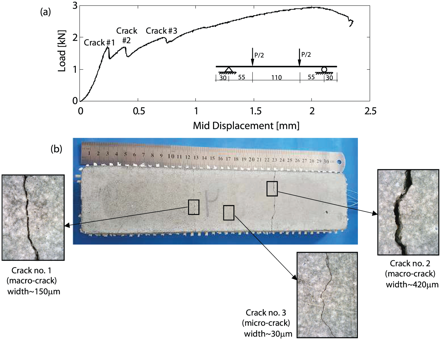
TRC beam: (a) load–displacement curve and (b) cracked beam after mechanical loading.
The structural response of the beam to the monotonic loading is typical to TRC structures. The main goal of this study is to investigate the capabilities of the electrical setups to distinguish crack width and thus identify cracking severity and magnitude of water infiltration.
Water detection—electrical short-circuiting two adjacent carbon rovings
The sensing capabilities of the carbon rovings take advantage of the continuous configuration of the carbon rovings, which enables to connect the ends of the rovings directly to the DAQ. Restricting the electrical terminals to the ends of the rovings limits the sensing capacities to an integrative mode and limits the system to identifying wetting events without the ability to identify the exact location of the event along the roving. Segmentation of the monitoring system can overcome this obstacle and is particularly relevant to pipeline applications, in which precast elements are placed head to tail, yielding a system that is segmented by nature. In such applications, the sensing concept adopted in this study aims to detect the wetting and the severity of the infiltration but is not designed to pinpoint the exact location of the event within the segment. On the other hand, since carbon rovings are an integrated part of the structural system, they continue to function also at scenarios of progressive failure mechanism where traditional sensing devices usually failed to produce meaningful information. 12 This is crucial in case of water pipe systems. In such case, it is important to have a reliable estimation of the magnitude of infiltration of the water and as a result to estimate the amount of water lost from the time it is detected till the time it is corrected. Furthermore, such a hybrid system that continues to function, both as a structural component and as a sensor, can be corrected and fixed and it is not necessary to replace the damaged segment.
The basic physical mechanism takes advantage of the manufacturing process in which two or more parallel carbon rovings are positioned side by side in each textile layer. The carbon rovings are placed parallel to the glass fiber rovings, so that when the TRC element is subjected to flexure, the carbon rovings become perpendicular to the newly formed cracked surface. It is assumed that as a result of water infiltration through the cracked zone, adjacent carbon rovings are electrically linked and the electrical signal of the rovings is, therefore, expected to change. The general concept of electrical short-circuiting two adjacent conductive rovings is based on the work by Quadflieg et al., 13 who studied the idea on the component level of stainless steel yarns, and on the work by Goldfeld et al., 14 who worked on the structural level of a stainless steel–based TRC beam. However, although the stainless steel yarns are inserted within the AR-glass textile as part of the textile production process, they do not add stiffness to the TRC structure and mainly serve as a sensory agent. Carbon rovings, on the other hand, have a preferable tensile stiffness, as can be seen in Table 1, and accordingly enable the development of a smart hybrid structure. In this study, the concept is investigated using two different electrical setups: two opposite out-of-phase Wheatstone bridges (DC circuit) and AC circuit. In the first electrical setup, both ends of the rovings are connected to the DAQ, while in the second electrical setup, only one end of each roving is connected to the DAQ.
The electrical setups are presented in the next section, followed by an experimental study of the interaction with a wet environment on two levels: the component level, using the mold described in section “Component level—bared carbon rovings,” and the cracked TRC beam level, presented in detail in section “Structural level—TRC beam specimen.”
On the component level, the influence of water on the electrical scheme is studied using a model apparatus that includes only the carbon rovings and a body of water. This case does not include a concrete component. Two parallel carbon rovings are installed in the mold and immersed in a water bath. The immersion of the mold into the water electrically connects the two rovings along the “window” over a length that is specified by the linear stage. The wetted profile zone along the rovings is specified according to the following profile: at t = 500 s, the window is immersed 6 mm into the water followed by three stepwise immersions of an additional 0.5 mm every 500 s until t = 2500 s, at which time the rovings are removed from the water following the same profile. The chosen profile has two purposes: first, by changing the wetted zone, the sensitivity of the electrical setup with respect to the magnitude of the wetting events may be investigated, and second, the time interval of 500 s enables to examine the stability of the electrical readings. This profile is implemented twice: first using distilled water and then using tap water. All tests are conducted on dry carbon rovings.
To further investigate the sensitivity of the electrical readings to distinguish different wetted zones, the profile is also examined for intervals of 0.3 and 0.1 mm. This set of experiments is conducted only with tap water.
The second level focuses on a TRC structural element and the electrical response to wetting of the cracked TRC beam, described in section “Structural level—TRC beam specimen.” Along with the effects identified on the component level, this level also includes the influence of the conductivity of the wet concrete on the electrical scheme. These tests are conducted by wetting each of the three cracks as well as the healthy zone along the beam. The discussion focuses on the response of the rovings located in the lower (tensioned) textile layer near the cracked face of the TRC beam.
After the beam was tested mechanically and cracks were formed (see section “Structural level—TRC beam specimen”), tests were conducted by wetting the specific zones along the lower face of the beam. Thus, to specify the cracked zones, molds made of isolated clay were constructed along the beam (see Figure 4). This configuration enabled each crack to be examined independently while keeping the rest of the beam dry. During wetting events, water covered the lower face of the cracked zone for about 1400 s. This independent investigation of each zone (cracked and healthy) allowed to explore the sensitivity of the electrical setups to distinguish crack severity and, as a result, the magnitude of water infiltration. Each of the three cracks (one micro-crack and two macro-cracks) and the healthy (non-cracked) zone are tested on a dry beam and include wetting each cracked zone with distilled water and tap water.
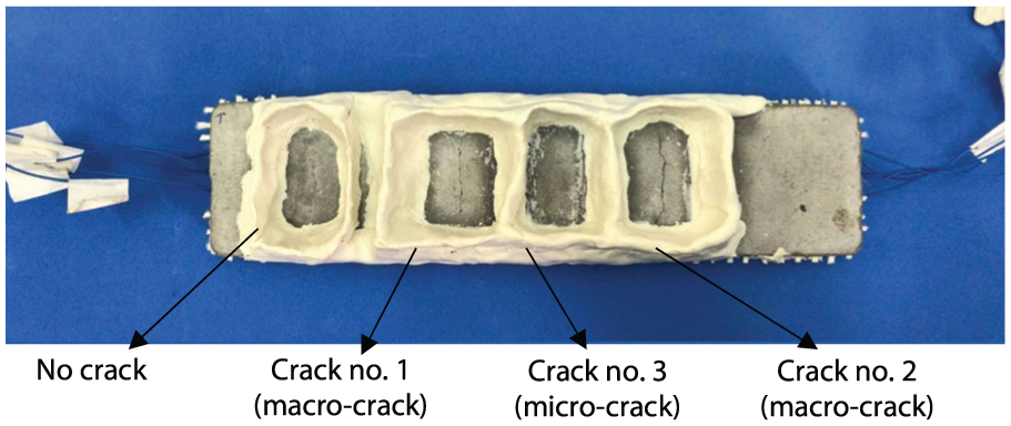
Cracked TRC beam with isolated mold.
Electrical short-circuiting two adjacent carbon rovings using two opposite out-of-phase Wheatstone bridges
This electrical setup examines the electrical mechanism created by wetting two adjacent carbon rovings in a setup that is based, conceptually, on a scheme presented by Goldfeld et al. 14 According to this scheme, each carbon roving is connected to a separate Wheatstone bridge setup. The high resistivity of the concrete body located between the rovings decouples the two bridges and allows to independently measure the voltage change due to straining.7,11 Upon infiltration of water through a crack, the bridges are electrically connected and a new circuit is formed: the conductive wet concrete and the conductive body of water electrically short-circuits the two bridges. In the work by Goldfeld et al., 14 two electrical schemes were offered for the connection of two parallel stainless steel yarns to the Wheatstone bridges. In the first scheme, which was called the in-phase setup, the two yarns were connected to the bridges symmetrically, while in the second scheme, which was called the out-of-phase setup, the terminals of the two bridges were flipped. They also showed that the second electrical setup amplifies the electrical reading and provides the system with a stable electrical signal. This study takes this concept one step forward and attempts to further amplify the electrical reading. Therefore, in addition to flipping the terminals of the rovings, the connection of the rovings along the external half bridges is changed.
Figure 5 presents a schematic layout of the proposed concept and its electrical scheme. In this setup, each carbon roving is implemented into the bridge as one of the resistors. In the scheme shown in Figure 5(a), Terminals A1 and B1 designate the independent connections of the first carbon roving to the first Wheatstone bridge, and Terminals A2 and B2 designate the independent connections of the second carbon roving to the second Wheatstone bridge.
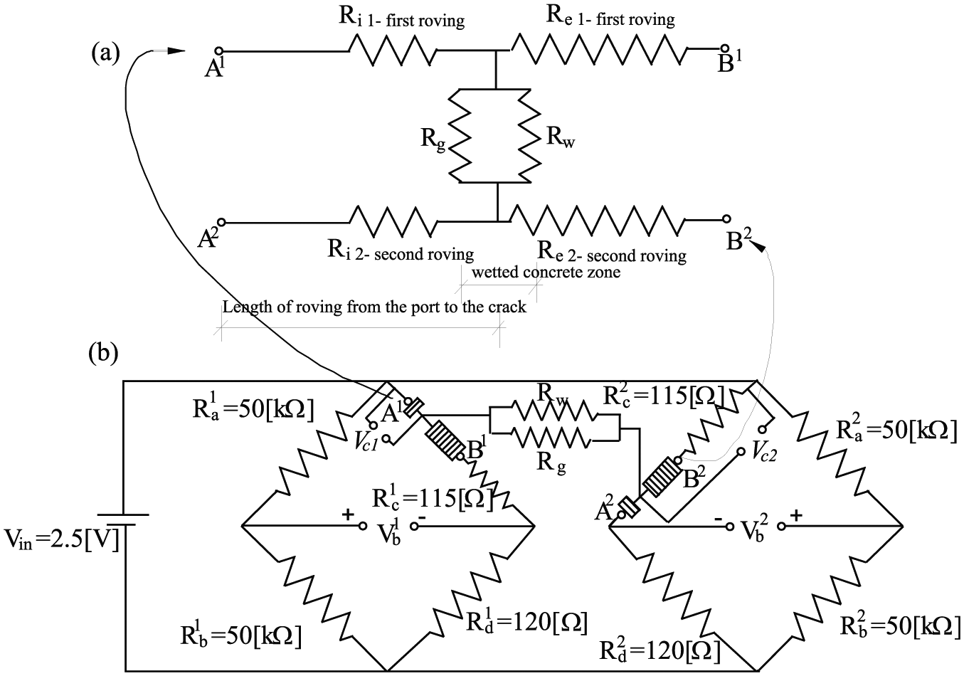
Electrical scheme of opposite out-of-phase Wheatstone bridge setup: (a) resistance layout of wetted rovings and (b) Wheatstone bridges.
To measure the resistance according to the above methodology, the carbon rovings are connected to a National Instruments (NI) signal conditioning module (NI-PXIe-4330) installed in an NI-PXIe-1078 chassis. The resistances of the resistors of half of the bridge, which are an integral part of the PXIe module, are identical (Ra = Rb); the resistance of the resistor of the quarter bridge completion, which is also integrated into the module, is Rd = 120 Ω; the external resistor is determined to be Rc = 115 Ω; and the excitation voltage is Vin = 2.5 V. Note that the external resistor Rc is not identical to Rd, which is the common implementation in such setups but is determined based on the resistance of the dry carbon roving, which is about 5 Ω. Therefore, Rc + Rroving in the dry position almost balances each bridge, thus increasing the range of the measured voltage due to wetting.
In Figure 5(b), the connection to the bridge is reversed, eventually amplifying the electrical reading. Ri1 and Re2 stand for the resistances of the first and second carbon rovings, from Terminals A1 and B2, respectively, up to the cracked cross section, while Re1 and Ri2 stand for the resistances of the first and second carbon rovings, from the cracked cross section to Terminals B1 and A2, respectively. Rg and Rw stand for the resistance of the concrete body and of the body of aqueous solution trapped within the crack, respectively.
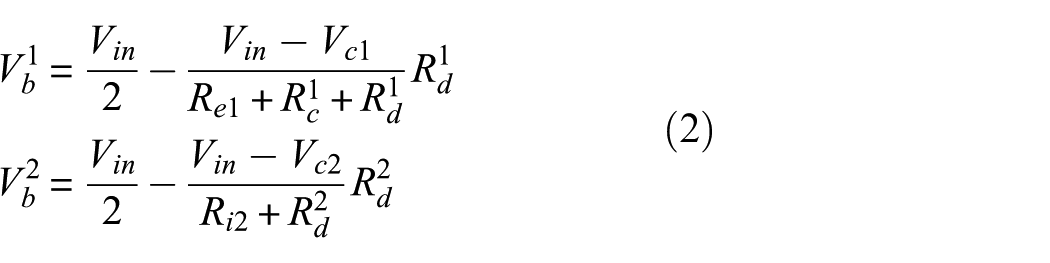
In the present electrical scheme, the symmetry of the connection of the resistors and the carbon rovings at the external half bridge is also reversed (see Figure 5). This opposite out-of-phase connection is found to be the configuration that most amplifies the electrical readings. In this configuration, when water electrically links the two Wheatstone bridges, the opposite out-of-phase installation of the rovings amplifies the change in the electrical current and, as a result, amplifies the measured voltage. Following Kirchhoff’s circuit law, the following two equations are derived
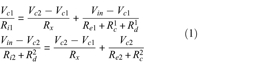
where Vc1 and Vc2 are the voltage over the cracked cross section (indicated in Figure 5), Rc and Rd are known resistors given in Figure 5(b), the excitation voltage is Vin = 2.5 V, and Rx =RwRg/(Rw + Rg) is the resistance of the concrete body between the rovings. The above equations can be solved for Vc1 and Vc2. Note that Vc1 and Vc2 cannot be measured and are only evaluated analytically in order to estimate the measured voltage across each bridge as
Analytical simulation
To demonstrate this concept, an analytical simulation is first presented. To estimate the measured voltage (Vb1 and Vb2) as a result of a wetting event, it is assumed that the location of the crack is known and so the resistances of the rovings up to the crack and from that point are known as well. The corresponding resistance values are taken to be
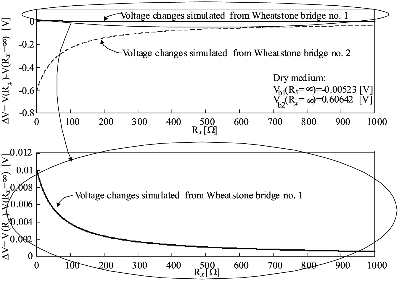
Electrical simulation of voltage change versus linked resistance for an opposite out-of-phase Wheatstone bridge setup.
Component level—bared carbon rovings
The interaction with a wet environment is first investigated experimentally using a model apparatus that includes only the carbon rovings and a body of water. Rx is thus replaced with Rw, and the two bridges are not connected in the dry state. The physical mechanism suggested for this configuration is that water links the two bridges ionically. Figure 7 presents the voltage readings along with the wetted zone (linear stage position), and it is clear that the electrical readings for wetting events with distilled water differ from those obtained with tap water. The voltage change caused by tap water is two orders of magnitude higher than that caused by distilled water. Furthermore, in the case of distilled water, the voltage changes over the two bridges are of the same order of magnitude, and no electrical short-circuiting is observed. It is therefore assumed that in the case of distilled water, the voltage readings are probably due to another environmental effect, such as temperature changes, rather than resistivity changes.
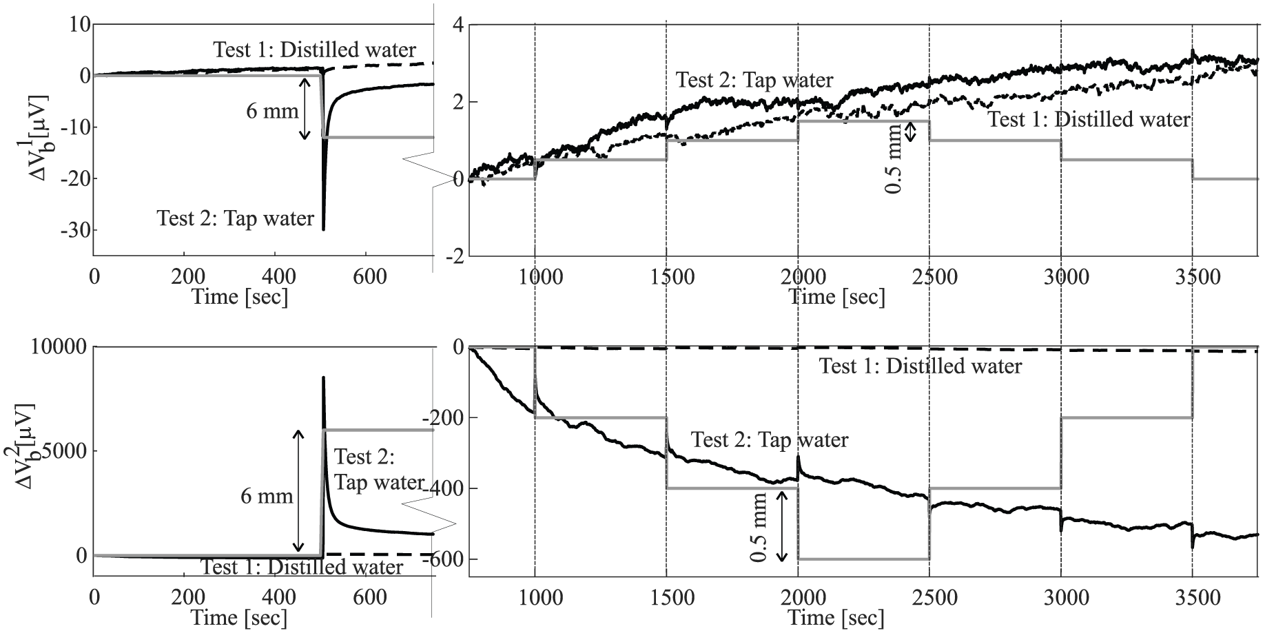
Voltage change due to wetting of two bared carbon rovings versus time—opposite out-of-phase Wheatstone bridge setup.
For the case of tap water, the wetting event and the ionic conductivity link the electrical circuits and yield significant voltage changes. The trend of the voltage readings for the two bridges is in opposite directions: the readings over one of the bridges increase, while those for the other bridge decrease, with an absolute value that is higher than the positive one. However, the wetting event is detected only when the wetted zone is actually changed and it is dependent on the wetted profile trend (increasing or decreasing), while along the constant wetting zone, a significant drift of the voltage reading is observed.
To investigate the sensitivity of the electrical scheme in the case of wetting with tap water, additional wetting event profiles are investigated (see Figure 8). The goal is to investigate the capability of the electrical setup to distinguish between different wetting zones as a starting point for the investigation of the magnitude of infiltration and severity of cracking within the TRC beam. It is evident from Figure 8 that the general trend of the electrical readings over the two bridges is the same for all three cases: one bridge exhibits an increase in voltage, while the other shows a decrease. The magnitude of the relative decrease in voltage change is much higher than the adjacent bridge. It is also seen that the voltage changes for wetting intervals of 0.5 mm are greater for intervals of 0.3 and 0.1 mm, and the differences between the changes for 0.3-mm intervals and 0.1-mm intervals are negligible.
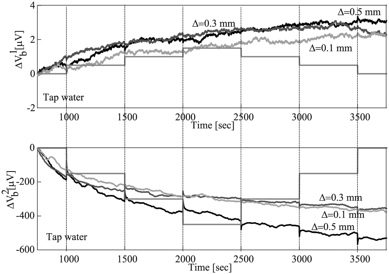
Voltage change due to wetting of two bared carbon rovings versus time—opposite out-of-phase Wheatstone bridge setup using tap water and various wetted intervals.
Structural level—cracked TRC beam
The second level in exploring the detection of wetting focuses on the cracked TRC beam. As shown before, the electrical response of the TRC beam to wetting is examined separately for the healthy zone and for each of the three cracked zones (Figure 9), the experiment is conducted twice: once with distilled water (dashed line) and then, after the beam is dried out, with tap water (solid line). The discussion focuses on the response of lower two rovings (the tensioned rovings) in the cracked TRC beam.
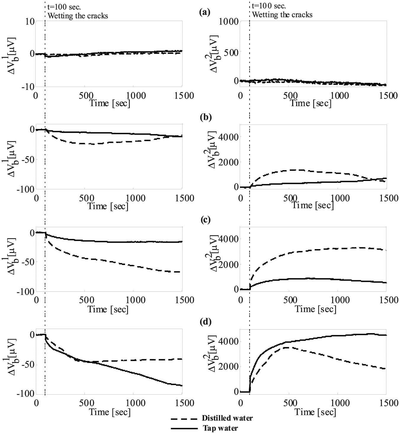
Voltage change versus time measured by opposite out-of-phase Wheatstone bridges setup due to wetting various zones along cracked TRC beam: (a) healthy zone, (b) cracked zone #3—crack width 30 μm, (c) cracked zone #1—crack width 150 μm, and (d) cracked zone #2—crack width 420 μm.
Figure 9 reveals that the wetting events of the cracked zones involving both distilled and tap water are captured by the sensory textile, while wetting of the healthy zone (Figure 9(a)) produces no notable voltage changes. In the case of the cracked zones (Figure 9(b)–(d)), the aqueous solution links the bridges and causes an electrical state that yields significantly different voltage readings across the two bridges. In one of the bridges, the current increases significantly and the monitored voltage change decreases, while in the other bridge, the electrical current decreases leading to higher monitored voltage readings.
A comparison between the electrical readings obtained using distilled water and tap water shows that in all cases, the wet concrete develops conductive properties that are similar to that of the integrated system. It is also seen that the effect of the type of aqueous solution on the electrical reading is different in the case of wetting micro-cracks and in the case of macro-cracks. In the case of the largest crack (crack no. 2, Figure 9(d)), tap water reveals voltage changes that are greater than those observed with distilled water, since in this case it is assumed that water penetrates into the crack and plays a significant role in linking the two bridges. However, in the case of micro-cracks (crack nos 3 and 1, Figure 9(b) and (c), respectively), distilled water reveals voltage changes that are greater than those observed with tap water. The reason for that is the chemical–mechanical phenomena involved with the infiltration of the aqueous solution into the cracked zone. It is affected by the properties of the concrete mixture, the type of the solution, and the reaction between them. In case of micro-cracks, each type of the aqueous solution reveals different mechanical–chemical phenomena. The tap water reveals a crack-healing, while the distilled water degrades the interfaces of the crack due to acid attack. The crack-healing phenomenon is induced by the tortuous surfaces of the crack that have some contact with each other enabling to transfer mechanical load. 19 Infiltration of tap water into the spaces along the crack’s interfaces motivates an internal chemical process of hydration of the unhydrated grains which eventually causes crack healing and therefore reduces the penetration of the tap water through the crack. On the other hand, distilled water leads to an opposite chemical phenomenon. The low pH level of the water degrades the concrete due to chemical process of acid attack 20 and accordingly the infiltration of the distilled water into the micro-crack is intensified. Both phenomena influence the electrical readings. The crack healing, motivated by tap water, reduces the permeability of the concrete and thus leads to smaller changes in the voltage reading. Acid attack, motivated by distilled water, increases the permeability of the concrete and thus enhances the infiltration of the solution into the crack leading to greater voltage changes.
Furthermore, it is clearly seen that the ability of the voltage readings to detect the wetting event depends on the width of the cracks. Generally, the wider the crack, the more stable and traceable the readings are. Figure 10 presents a comparison between the voltage readings over the second bridge obtained when the three cracked zones and the healthy zone are wetted with tap water. Note that the voltage readings obtained by wetting the healthy zone and micro-crack zones, which are considered to be the design state in TRC structures, are similarly low compared with the wetting events of the macro-crack zones, representing the damaged state of the TRC structure.
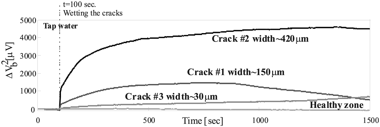
Voltage change versus time measured by opposite out-of-phase Wheatstone bridges setup due to wetting of various cracked zone along TRC beam with tap water.
These observations indicate that the sensory textile effectively detects the wetting of the cracked beam. The opposite out-of-phase connection of the rovings provides the system with a stable sensing signal. This configuration utilizes the electrical scheme proposed by Goldfeld et al.7,9,12 for monitoring the structural state through strain measurements, providing the TRC element with a multi-functional sensory capacity, both in terms of structural strain and in terms of exposure to water.
Electrical short-circuiting two adjacent carbon rovings using an AC setup
The second electrical setup investigates the electrical mechanism of two adjacent carbon rovings in an AC electrical circuit that are electrically connected upon infiltration of water through a crack, so as to form a new electrical reaction. The electrical layout of this setup is illustrated in Figure 11 and includes two adjacent carbon rovings. One end of one roving is connected to one terminal of an AC power source, whereas the adjacent end of the adjacent roving is connected to the other terminal of the same source.
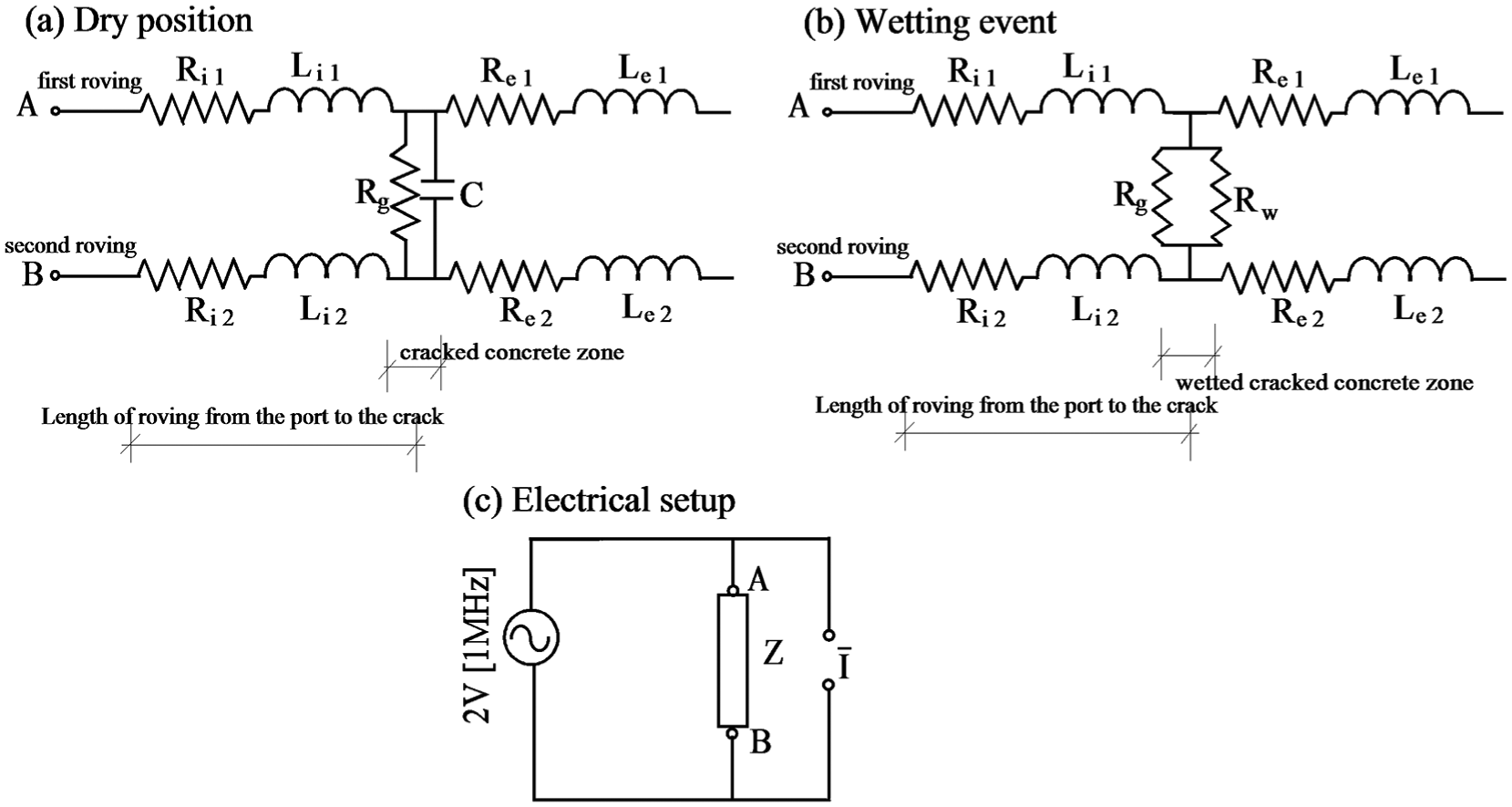
Electrical scheme of AC setup: (a) resistance layout of dry concrete, (b) resistance layout of wetted rovings, and (c) AC setup.
The measurement equipment is a Wayne Kerr LCR Meter 4300, with an RMS voltage of 2 V (amplitude of 2.82 V) and 1 MHz frequency. The device is designed to measure impedance, that is, the relationship between voltage and current (Zx) and the phase between them (ϕ). The resistance Rx and the reactance Xx of the system can be evaluated using the relationships
The hypothesis of this concept is that the electrical characterization due to wetting is completely changed. In the dry state (Figure 11(a)), the system includes the two conductive rovings and the high resistivity body of dry concrete between them. Each carbon roving is characterized as resistor and inductor. The system at dry position (conductive rovings and the body of concrete) is, therefore, characterized as a capacitor. The higher the resistivity of the medium between the rovings, the more dominant the capacitor effect. Wetting the interface between the rovings increases the conductivity of the medium between them, leading to a decrease in the capacitance parameter so that the electrical response is governed by a new conductor that electrically short-circuits the rovings (Figure 11(b)). The assumption is that the AC electrical setup captures these electrical phenomena.
Component level—bared carbon rovings
To demonstrate this concept, the first experimental phase on the component level includes a couple of bared carbon rovings and a body of water, using the mold described in section “Component level—bared carbon rovings.”Figure 12 gives the impedance readings, Zx, and the phase, ϕ, which are the measured values, and the resistance, Rx, and reactance, Xx, which are the evaluated values, for both distilled water (dashed lines) and tap water (solid lines).
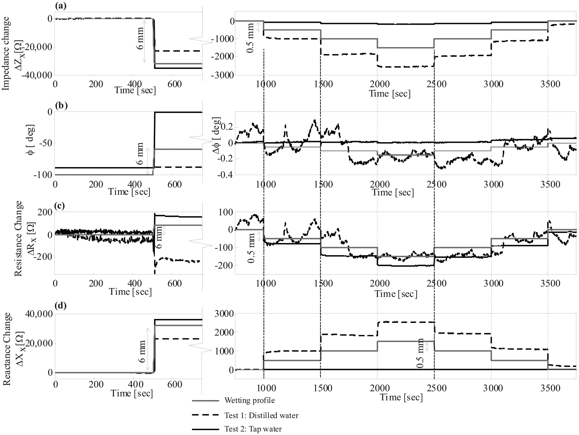
Electrical readings versus time measuered by AC setup due to wetting of two bared crabon rovings: (a) impedance change, (b) phase, (c) resistance change, and (d) reactance change.
It is clearly seen that the wetting events are well detected by the monitoring system. Moreover, it is evident that the conductivity of the water directly affects the electrical response and its characterization. Figure 12(b) shows that the initial value of the phase is about 88°, meaning that in open air, the two dry rovings are characterized together as a capacitor. When the water electrically links the rovings, the response depends on the type of water: distilled water has almost no influence on the phase, and the electrical response is governed by the capacitance. In this case, the reactance change is more pronounced than the resistance change (see dashed lines in Figure 12(c) and (d)). When the rovings are linked with tap water, the phase ϕ drops from almost 90° to almost 0°; the capacitance effect is eliminated and the impedance change is governed by resistivity changes (see solid lines in Figure 12(c) and (d)). These results indicate that the level of the conductive medium between the rovings has a major effect on the characteristic electrical response and therefore can be used for sensing purposes for leakage detection.
The sensitivity of this electrical setup is investigated in Figure 13 for tap water and three wetting intervals (0.5, 0.3, and 0.1 mm). It is clear that the AC electrical setup is sensitive to the wetted intervals and that the electrical readings are almost proportional to the wetted zone. Furthermore, changes in the wetted zone, of even 0.1 mm, were clearly reflected by stable impedance, resistance, and reactance electrical readings. Figure 13(c) and (d) shows that the resistance change is greater by about two orders of magnitude than the reactance change. These observations verify that wetting with a conductive aqueous solution changes the electrical characteristic response and leads to pronounced and stable readings.
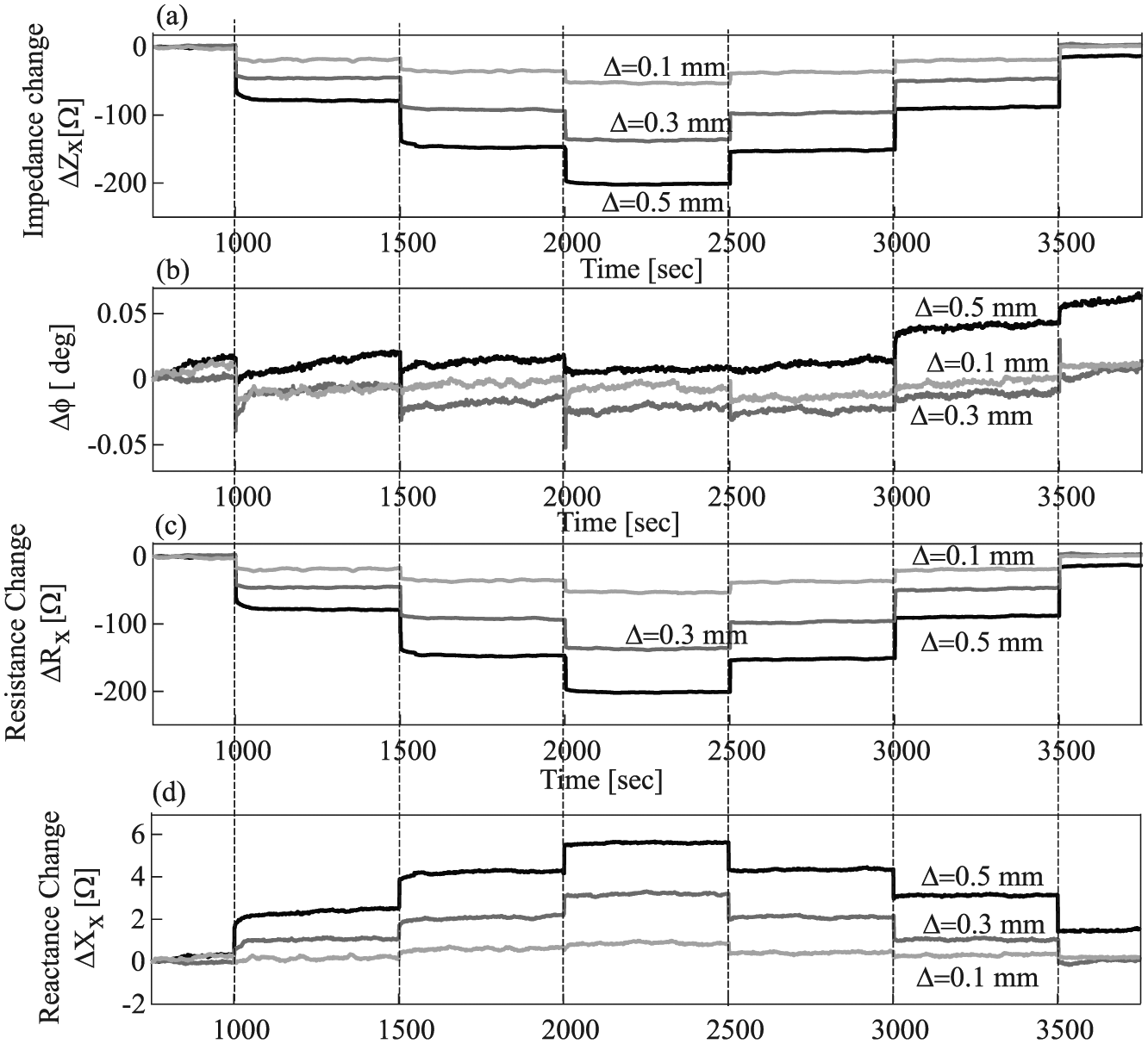
Sensitivity investigation using various intervals and tap water measured by AC setup: (a) impedance change, (b) phase change, (c) resistance change, and (d) reactance change.
Structural—cracked TRC beam
The second level of the investigation focused on a cracked TRC beam. The electrical response of the TRC beam to wetting is examined separately for a healthy zone and for each of the three crack zones (Figure 14). The discussion focuses on the response of lower two rovings (the tensioned rovings) in the cracked TRC beam. Here again, the wetting test is conducted twice, once with distilled water (the dashed lines) and then, after the specimen is dried out, with tap water (the solid line). All tests are conducted on dry beam.
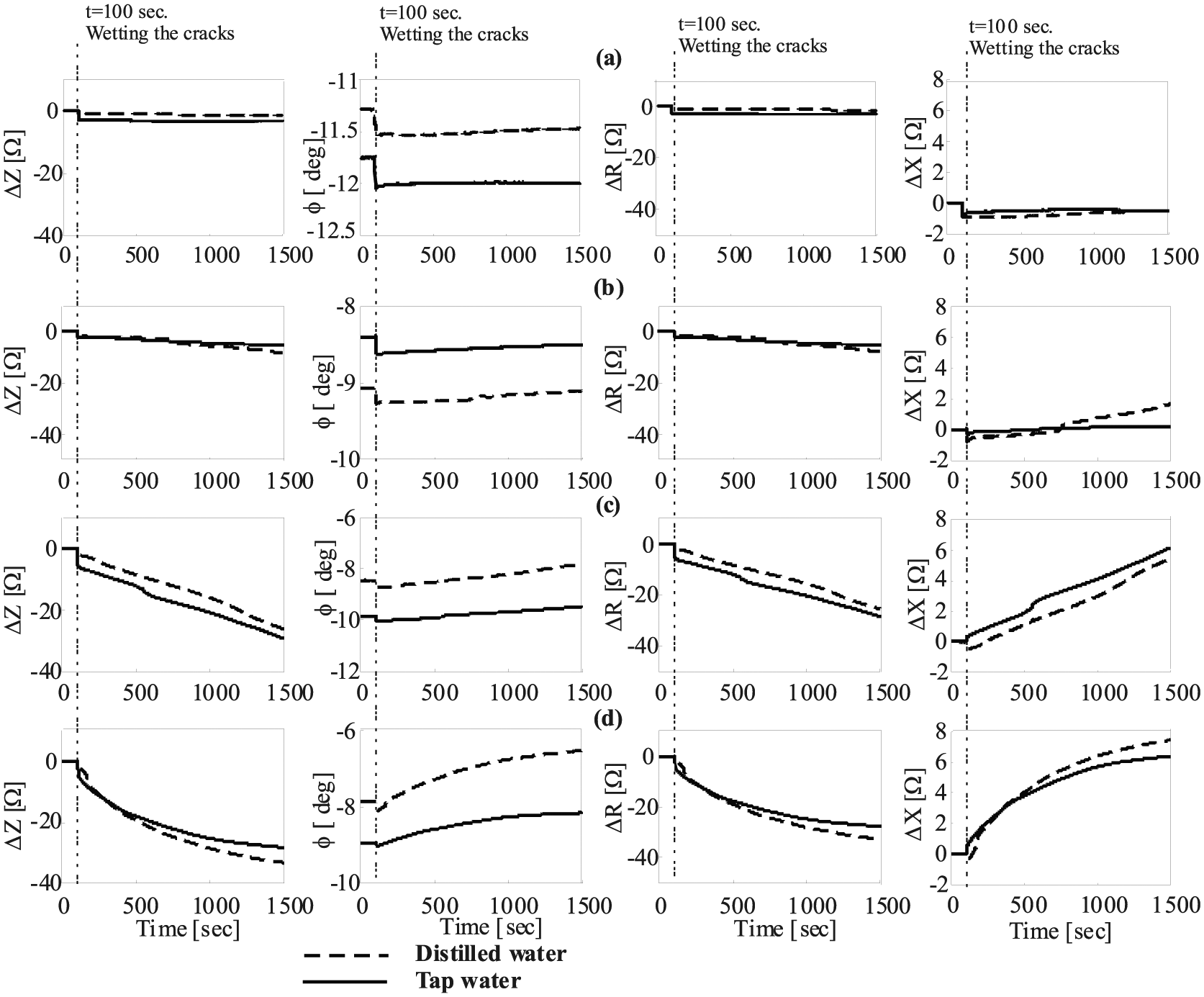
Electrical readings versus time measured by AC electrical setup due to wetting various cracked zone along TRC beam: (a) healthy zone, (b) cracked zone #3—crack width 30 μm, (c) cracked zone #1—crack width 150 μm, and (d) cracked zone #2—crack width 420 μm.
Figure 14 reveals that the wetting events of the cracked zone involving both distilled and tap water are captured by the sensory textile, while wetting of the healthy zone produces no notable electrical reading changes. It is also seen that wetting events with tap water and with distilled water yield almost the same electrical readings, which means that the conductivity of the wet concrete plays a significant role in the new AC electrical circuit. The measured impedance phase, ϕ, is about 10° in all tests and changed slightly due to wetting. This implies that the conductivity of the dry concrete, which is relatively low, reduces the influence of the capacitance in the electrical circuit. It can also be seen that in all wetting scenarios, the changes in the measured resistance, due to wetting, are one order of magnitude greater than the changes in the reactance, implying that in the case of cracked TRC beam, the resistivity effect is more pronounced than the reactance effect.
Figure 15 presents a comparison between the electrical readings (impedance, phase, resistance, and reactance) for the wetting events along the healthy zone and the various cracked zones. It is clear that crack severity influences the magnitude of all electrical measures. In general, the wider the crack, the more water infiltrates, leading to higher measured values. Here again, the electrical measures obtained by wetting the micro-crack (crack no. 3), which is considered to be the design state of TRC structures, are very similar to the values measured for the healthy zone (in which no cracks were detected). Furthermore, the micro-crack readings are much lower than those obtained for the macro-cracks, a finding that reveals the potential of this electrical configuration to quantitatively estimate cracking severity.
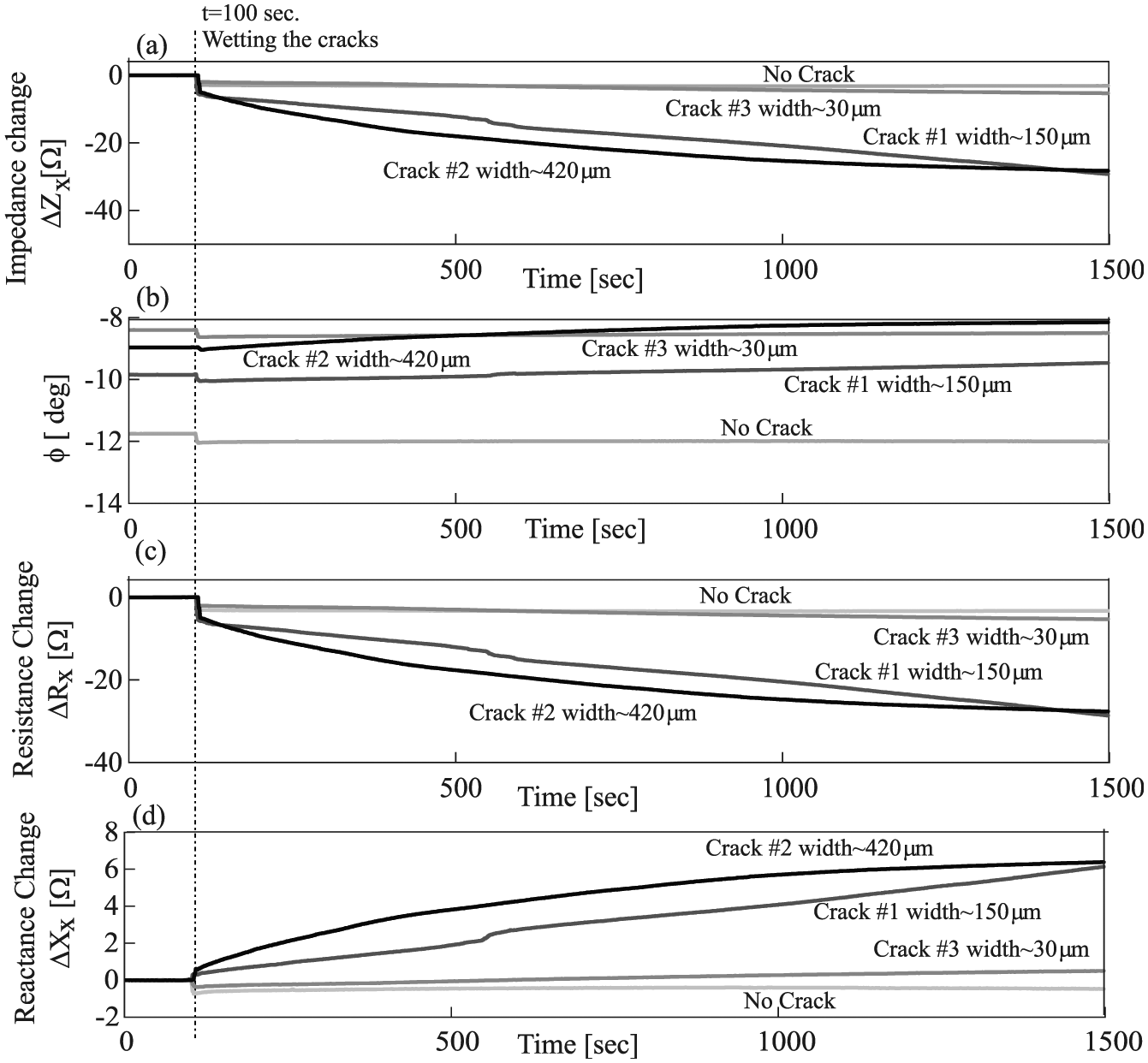
Electrical readings versus time measuered by AC electrical setup due to wetting various cracked zones along TRC beam by tap water—sensitivity investigation: (a) impedance change, (b) phase, (c) resistance change, and (d) reactance change.
Note that each test was terminated after 1500 s, and in some cases the electrical reading had not yet completely stabilized. It is probably due to the penetration of water into the cracked zone and internally, along the rovings within the beam.
The above results demonstrate the capabilities of the AC setup not only to identify wetting events but also to characterize them as well. The sensitivity of the results with respect to the different crack severity paves the way to the future development of a quantitative identification procedure.
Conclusion
This study explored the sensitivity of a smart carbon-based TRC element to detect various wetting events by two electrical setups. The sensing concept adopted for both electrical setups assumes that electrical signal due to wetting is obtained by electrical short-circuiting two adjacent carbon rovings.
The first electrical setup connected the two rovings to two opposite out-of-phase Wheatstone bridges which leads to amplified electrical readings that can clearly distinguish the magnitude of water infiltration, which is directly related to the severity of the crack. Moreover, the readings obtained by the opposite out-of-phase Wheatstone bridge setup successfully distinguish between wetting of no-crack and micro-crack zones, considered to be the healthy and design states of the beam, and wetting of macro-cracks, considered to be the damaged state. Connecting the rovings to Wheatstone bridges was successfully implemented in the literature for structural sensing (strain and damage), thus it is advantageous to use the same electrical setup for both structural and functional sensory purposes.
The second electrical setup used AC circuit, which leads to very promising results. The electrical readings were stable and sensitive and directly associated with the electrical short-circuiting due to the wetting events. It was shown that the conductivity of the dry concrete, even though it is relatively low, links between the rovings and the electrical readings are affected mainly by resistance and less by capacitance. Due to infiltration of water within the cracked zones, the readings reflect a change in the electrical response, implying that the water and conductivity of the wet concrete body play a significant role in the new electrical circuit. This new circuit is governed by changes in resistance and in reactance. The resistivity decreases and the reactance, which is governed by capacitance, decreases but is less affected. Moreover, the readings obtained according to this setup were found to be very sensitive to crack severity and stable during the wetting events. These promising results pave the way to an advanced investigation that will establish a quantitative relationship between the electrical readings and the magnitude of water infiltration as a result of crack severity.
Footnotes
Acknowledgements
The authors acknowledge the support provided to this study by the American Technion Society within the framework of the Interdisciplinary Eco-Engineering Research Center: Philip and Harriet Klein Contribution. The study was conducted at the Technion with the assistance of Eng. Barak Ofir, Mr Elhanan Yitzhak, and the staff of the National Building Research Institute. The authors gratefully acknowledge their partners at the Institute for Textile Technology at RWTH Aachen University, Germany, under the leadership of Prof. Thomas Gries, for supporting with the textile production.
Declaration of conflicting interests
The author(s) declared no potential conflicts of interest with respect to the research, authorship, and/or publication of this article.
Funding
The author(s) disclosed receipt of the following financial support for the research, authorship, and/or publication of this article: This work is supported by the BMBF—MOST Joint German-Israeli Water Technology Research Program (grant no. WT1602/02WIL1452).