






Abstract
Composite structures are assertively used for new airframe designs and manufacturing in military aircrafts because of superior strength-to-weight ratios and fatigue resistance. Because the composites have different fatigue failure characteristics compared with metals, it is necessary to develop different approaches for the composite fatigue design and testing. In this study, we propose an in situ damage evaluation technology with high spatial resolution during full-scale fatigue testing of composite aircraft structures. For real composite structure development considering composite fatigue characteristics, full-scale fatigue and damage tolerance tests of the composite fuselage structure were conducted to evaluate the structural characteristics. In the meantime, the laser ultrasonic nondestructive inspection method, called an angular scan pulse-echo ultrasonic propagation imager, which is fully noncontact, real-time, and portable to position it in between the complex test rigs, is used to observe in situ damage growth of the composite. Finally, the verification procedure assisted by the angular scan pulse-echo ultrasonic propagation imager assures no growth of the initial impact damages after lifetime operation and proves the damage tolerance capability of the developed composite fuselage structure.
Keywords
Introduction
Fiber-reinforced composite materials are considered the core technology for weight reduction of aircraft structures. There are many kinds of aircraft structures made of composite materials with the help of tailoring and optimizing the composite structural characteristics. One of the main advantages of the composite material compared with the metal is its high-specific strength and stiffness. In addition, the direction of reinforced fibers can be designed considering the structural purpose for the optimization. The material density of carbon–epoxy composite (1–2 g/cm3) is much lower than that of titanium (4–5 g/cm3), aluminum (2–3 g/cm3), and steel (7–8 g/cm3), which makes it possible to reduce the aircraft structural weight approximately 30%. These composites have large elastic range with less plastic deformation and show a low strain level.1,2
A disadvantage of a composite is its inhomogeneity. The fiber has good tensile properties but poor compressive properties. These composite structures have many fabrication variables as well as the design variables, which means the exact material properties can be evaluated when the composite structure is fabricated as initially designed. It takes a long time to define the material data of composites widely, especially for the fatigue and damage tolerance data. In addition, the composites have high stiffness with low ductility, and the impact energy generates atypical damages and cracks in the composite. Studies on the fracture mechanism made by impact damage and cracking have been conducted based on the micro/macro crack initiation and crack growth in the fiber and matrix of the composite.3–8
However, because composites are inhomogeneous, and ply-stacked structures in general, it is common to have in-plane delamination and internal damage, which are difficult to detect and define as the standardized damage. As a result, statistical damage tolerance and probability analysis have been required. The electrical conductivity of the composite is lower than that of metal, it is susceptible to the lightning, and the additional copper mesh on the skin is required in specific regions as a result. These complicated fabrication processes raise the manufacturing cost and quality deviation, which require more-precise process control and authentication.
For the application of composites in aircraft structures, fatigue characteristics should be considered, along with uncertainty. The S–N curve of composites is flat compared with that of metals, which is good for the fatigue performance. However, the composite shows a large deviation and scatter factor on the fatigue characteristics, and it is also susceptible to humidity and temperature. As a result, the design of composite structures requires enough margin of the safety factor to meet the fatigue life requirement. However, the operating aircraft structures are exposed to impact damage, so they should also maintain the structural integrity with the damage caused by unpredictable impacts. As a result, the damage tolerance design concept should be applied on the composite aircraft structure and the damage should not grow during the designed lifetime. Finally, a full-scale aircraft structural fatigue and damage tolerance test should be conducted to ensure that the damages do not grow to meet the structural integrity after whole lifetime of usage.9,10
The impact damage in the composite is hard to detect and define, and it is difficult to predict whether it will grow or not. In addition, it is hard to define the effect of the damage on the total fatigue life of the aircraft. To ensure the structural integrity and fatigue life with the assumption of damage no-growth, the design limit load test (DLLT) and design ultimate load test (DULT) are conducted on the full-scale specimens in general. However, this evaluation logic does not include the specific analysis of the real damage behavior with a damaged area. As a result, the tested structure can be certified to have structural integrity, even though the relations between the design safety margin and the local damages are not defined in detail.
In this study, a fatigue and damage tolerance test was conducted on the full-scale composite fuselage structure, which includes barely visible impact damages (BVIDs), visible impact damages (VIDs), and large impact damages (LIDs). The initial damages are defined and evaluated by angular scan pulse-echo ultrasonic propagation imager (PE UPI) to check the growth before and after the fatigue life cycle test. The angular scan PE UPI enables in situ nondestructive evaluation (NDE) during the full-scale fatigue test of which complicated test rigs does not allow access of conventional contact ultrasonic testing devices. This procedure can define the damage to grow or not in detail before the limit load and ultimate load test. This damage evaluation process shows a new possibility to predict the structural integrity of the fatigue life and damage tolerance, with the real-time and visualized damage evaluation method with high spatial resolution.
Damage tolerance design process for composite structures
Various material property tests evaluate the reliability of composite structures after fabrication, even though the composites have various advantages. The fabricated composite structure may include microscale material defects with macroscale manufacturing process error such as pore, microcrack, delamination, scratch, impact damage. These defects can lead to the initial crack and crack growth in the specific structural load condition as well as the degradation of composite properties. The crack generated by the defects can grow under the specific fatigue load to cause sudden fatigue failure of the structure. These defects should be evaluated not to grow under the operational load condition by nondestructive inspection (NDI) process, which is necessary to use the material in aircraft structures.
A fatigue test on the composite specimens, which had representative initial damages, was conducted to identify the severe damage case of composite fatigue life. The damages were an open-hole, delamination, scratch, and compression after impact (CAI), and the fatigue tests were conducted under the cyclic load in a high operating temperature of 55°C and extreme humidity of 95% conditions. The open-hole specimen showed the smallest life cycle among the damaged composite specimens. After the sample fatigue test, the damage tolerance design margin could be evaluated based on the static failure tests of the open-hole damaged specimens. As a result, the aircraft structure was initially designed and sized based on the open-hole damage tolerance design criteria, and the full-scale aircraft fatigue test should be performed to confirm the structural integrity and the fatigue life at the end of the development process.
The aircraft structure consisted of solid laminates and sandwich composites made by an autoclave curing process, and artificial BVIDs were made on the low static safety margin area. A specially designed impactor was used to make the impact damages on the surface of the composite structures by considering the impact energy, structural shape of impact locations, and structural boundary conditions to meet the “barely visible” requirement. The impact damages on the surface of the composite structures are shown in Figure 1 with test conditions in Table 1. The depth of the dent and visibility was determined on each damage, as shown in Figure 1.
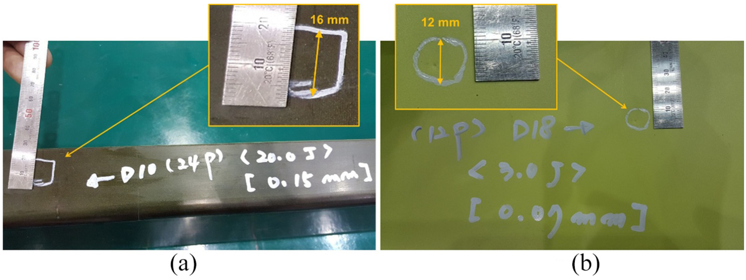
BVIDs on the composite components before aircraft assembly: (a) wing spar flange: impact energy (20.0 J)/dent depth (0.15 mm) and (b) tail wing upper skin: impact energy (3.0 J)/dent depth (0.07 mm).
Conditions for impact-induced damage generation.

Full-scale fatigue test
The fuselage was constructed by uni-directional and fabric carbon/epoxy laminate and honeycomb sandwich. All the skins and main structures used the composite materials, and a small amount of metals was used on the engine mounting structure (EMS), hinge fittings, lugs, landing gear supporting structures, and some part of the main bulkhead. The load enhancement factor (LEF) for this composite–metal hybrid structure was 1.127 for the full-scale fatigue test. The initial BVIDs were generated during the component fabrication and structural assembly process of the full-scale fatigue test specimen.
A full-scale fatigue test for the composite structure was conducted according to the following process. First, the fatigue test spectrum was derived based on the initial mission profile. The composite structure was fabricated including the initial BVIDs, and the two-life fatigue load was applied onto the structure.
As shown in Figure 2, after the two-life fatigue test, the VIDs were made by hammer striking on the low-marginal areas of the laminate and sandwich skins, and then the one-life fatigue test was continued. These damages were generated after a preliminary impact test on the equivalent specimens in which the proper impact energy level up to 50 J could be obtained. Because the composites have high stiffness and elastic properties, the scale of the dent on the skin was not linear to the applied energy. It was hard to make a proper dent on the surface just before the critical energy level, but there was large damage inside and outside when the energy level was just over the critical level. In addition, the different structural boundary conditions at each point made different damage levels, even though the skin had the same thickness. As a result, different variables were set up to make proper VIDs for the full-scale damage-tolerant test.
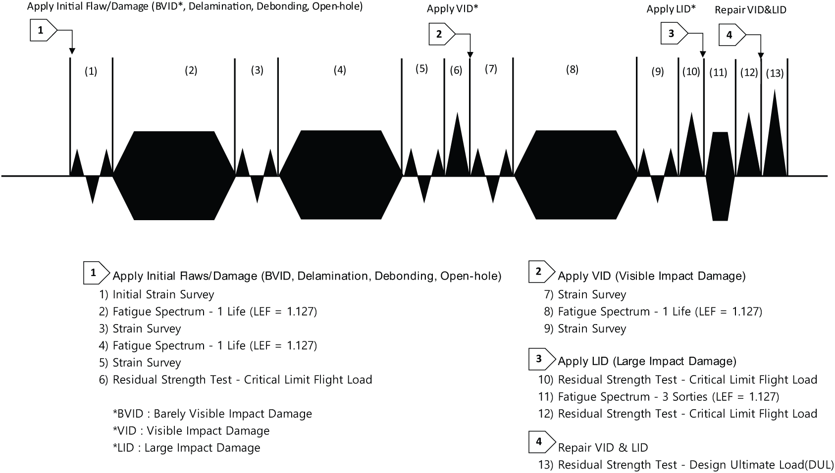
Aircraft structure fatigue/damage tolerance test procedure with Category I, II, and III damages.
For a honeycomb sandwich skin, the impact energy generally makes outer surface damage severe. In addition, a honeycomb core dent and facesheet delamination were generated at the same time. The shape of the outer surface dent is clear enough to define as VID. These impact damages should not have an effect on the structural integrity, and the damage should not grow after the additional one-life fatigue test. Figure 3 shows the VID on the sandwich skin of the structure.
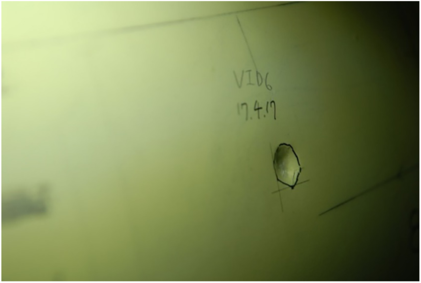
VID on the honeycomb sandwich skin.
However, it is also difficult to define the relations between the impact energy and the visual damage level on the solid laminate composite. In some cases, high impact above the designed energy level could not generate even BVID on the outer surface of the solid laminate, but there was large and severe damage with fiber breakage on the inner surface. Figure 4(a) shows the outer surface of the impact point, and the dent was under the BVID level. In addition, Figure 4(b) represents the inner surface with a large damage area, including fiber breakage. Even though this impact energy was enough to cause severe damage to the laminated skin structure, it was hard to detect from the outer side with a visual inspection method. As a result, this type of high impact energy damage with barely visible characteristics should be contained in the damage tolerance test as the most critical undetectable damage type. The composite structure should be designed to withstand this type of damage, and the structural integrity with a damage no-growth requirement should also be confirmed. After the implant of the initial damages on the composite structure, the fatigue life with damage tolerance test was conducted.
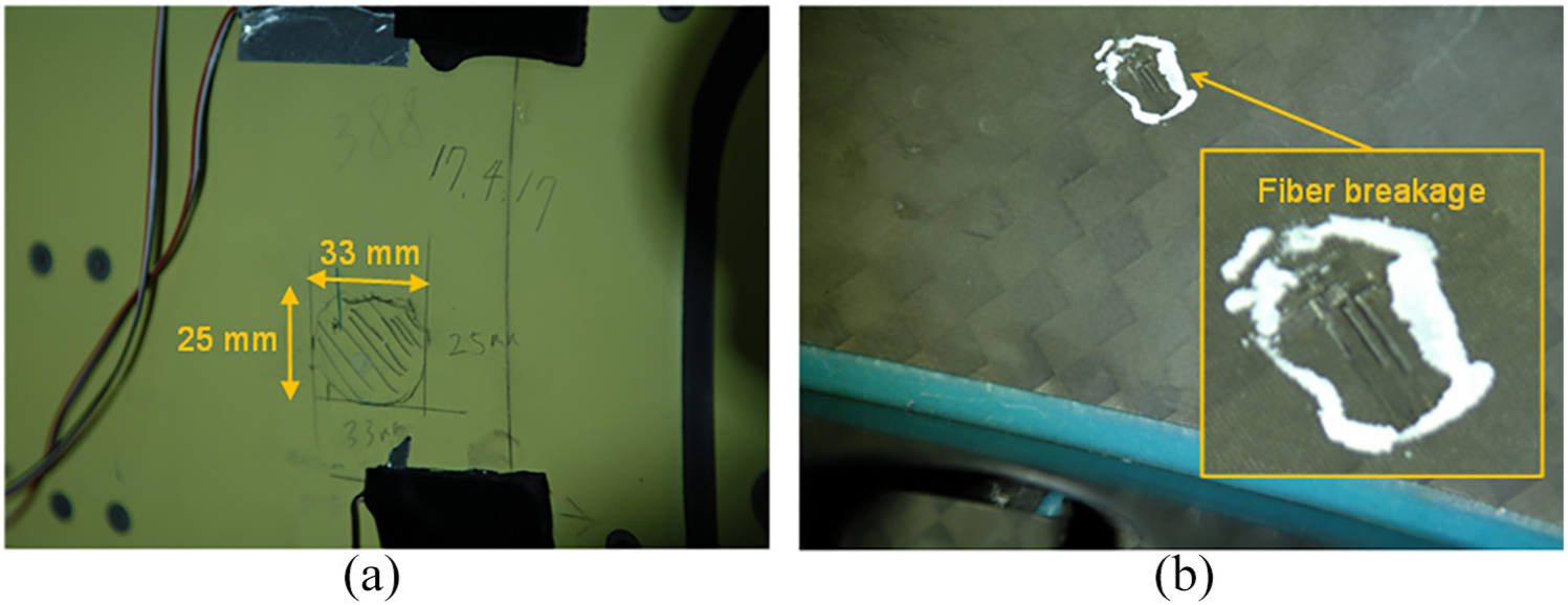
VID on the solid laminate skin: (a) outer damage and (b) inner damage.
After the one-life test, LIDs were applied on the minimum structural margin area. The fatigue cycle was conducted for three sorties as the minimum period for damage detection, and the VIDs and LIDs were totally repaired. Finally, an ultimate load test was conducted to confirm the structural integrity of the aircraft structure, which had finished the fatigue life cycles.
Damage evaluation
There are not many in situ NDE technologies that can quantitatively assess the growth of composite impact damage during the full-scale fatigue test. The typical manual A-scan was not able to be applied because complicated fixtures, loading and sensing devices did not allow access of contact ultrasonic testing devices. In addition, the inspection results are highly dependent on material properties and thickness as well as inspectors’ skill. Sometimes, probe contact and couplant application are not allowed. Recently, scanning laser ultrasonic methods and ultrasonic propagation imaging technologies have shown high feasibility for an in situ and remote NDE tool during the full-scale structure tests.11–13 The laser ultrasonic propagation imager (UPI) is classified into guided wave UPI and bulk-wave ultrasonic propagation imager (B-UPI), depending on the laser ultrasonic modes used. The B-UPI is classified again into pulse-echo and through-transmission systems. In the PE UPI, the ultrasonic generation and sensing laser beams are coincident at one point on the target. The generated ultrasound will be propagated over the thickness and then reflected. The reflected wave is captured by another sensing laser. The sensing mechanism at one point is repeated as the laser beam is moving during the scanning of the target surface. The typical scanning mechanisms are linear and angular scan modes. Linear scan is realized by an X-Y linear translation stage and angular scan is done by a laser mirror scanner. The laser mirror scanner (LMS) makes possible a rapid raster scan based on angular motions of the two laser mirrors mounted on the galvano-motors in the scanner. Figure 5(a) shows the angular scan PE UPI system, which includes a Q-switched laser as the generation laser and a laser heterodyne interferometer as the sensing laser, and beam combination optics and a galvano-motorized mirror scanner. The system body includes controllers for the two lasers and the LMS, as well as a data acquisition board. They are all synchronized for rapid scanning measurement up to a pulse repetition rate of 5 kHz. The system body also includes a graphical user interface (GUI) platform for automatic inspection, damage visualization in real time, and post image processing. The basic inspection result is PE ultrasonic wave propagation imaging (UWPI) video, which is generated right after the scanning in real time. 15 In addition, various time window amplitude mapping (VTWAM) can be applied as post processing to enhance damage visualization. 16 Figure 5(b) shows how the system implemented for in situ NDE of the full-scale composite fuselage during the damage tolerance test.
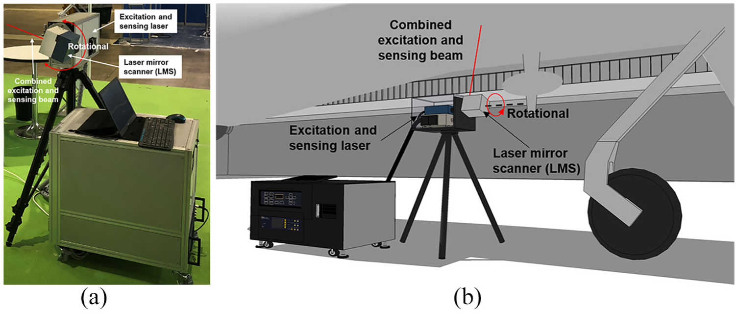
(a) Configuration of angular scan pulse-echo ultrasonic propagation imager 14 and (b) implementation of system for in situ NDE of a fuselage section.
In situ NDE results
Damage evaluation was conducted on the BVID and VID area in the solid laminate and sandwich skin for the fuselage. Impact damages were visualized using PE UWPI freeze frame and VTWAM, which are damage visualization techniques in angular scan PE UPI. Figure 6 shows VID on the honeycomb sandwich skin structure. The circular dent shows that the sandwich outer skin was damaged with fiber breakage. The scanning area of the combined sensing and excitation laser beam was 100 mm × 100 mm, and the standoff distance between the fuselage skin and the UPI scanning laser head was 1.86 m, and fully noncontact measurement was conducted. Figure 5 shows typical inspection configuration and it should be noted that the line of sight is very limited until the target to be inspected by fixtures, and loading and strain sensing equipment. The sampling frequency of the ultrasonic wave was 10 MHz, and the scanning interval was 0.25 mm. The pulse-echo ultrasonic wave propagation video was obtained in real time after scanning. The total scanning time for the area of the interest of 100 mm × 100 mm was 32 s under a 5-kHz pulse repetition rate.
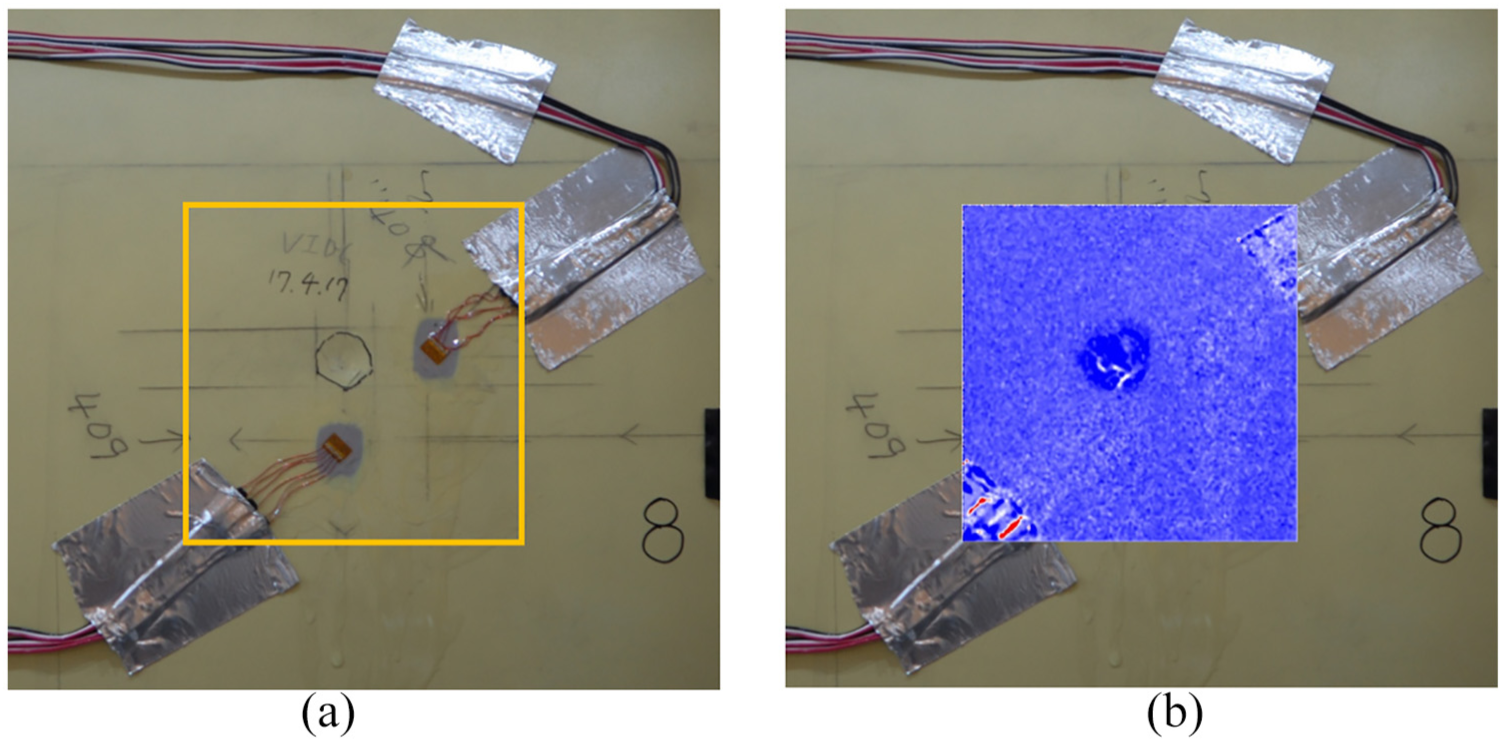
NDI and visualization of the impact damage on the sandwich fuselage skin: (a) scan area and (b) inspection result.
Figure 6 shows the scan area and the visualization result of the impact area before the fatigue test. The circular dark region shows the impact damage area, and the white lines show fiber breakage on the overlapped image. Figure 7 shows a comparison of the damage before the fatigue life test and after the test where strain gauges are also visible but not for the NDI but for the fatigue test. The impact damage did not show visible growth detectible by the angular scan PE UPI with a spatial resolution of 0.25 mm during the life cycle test.
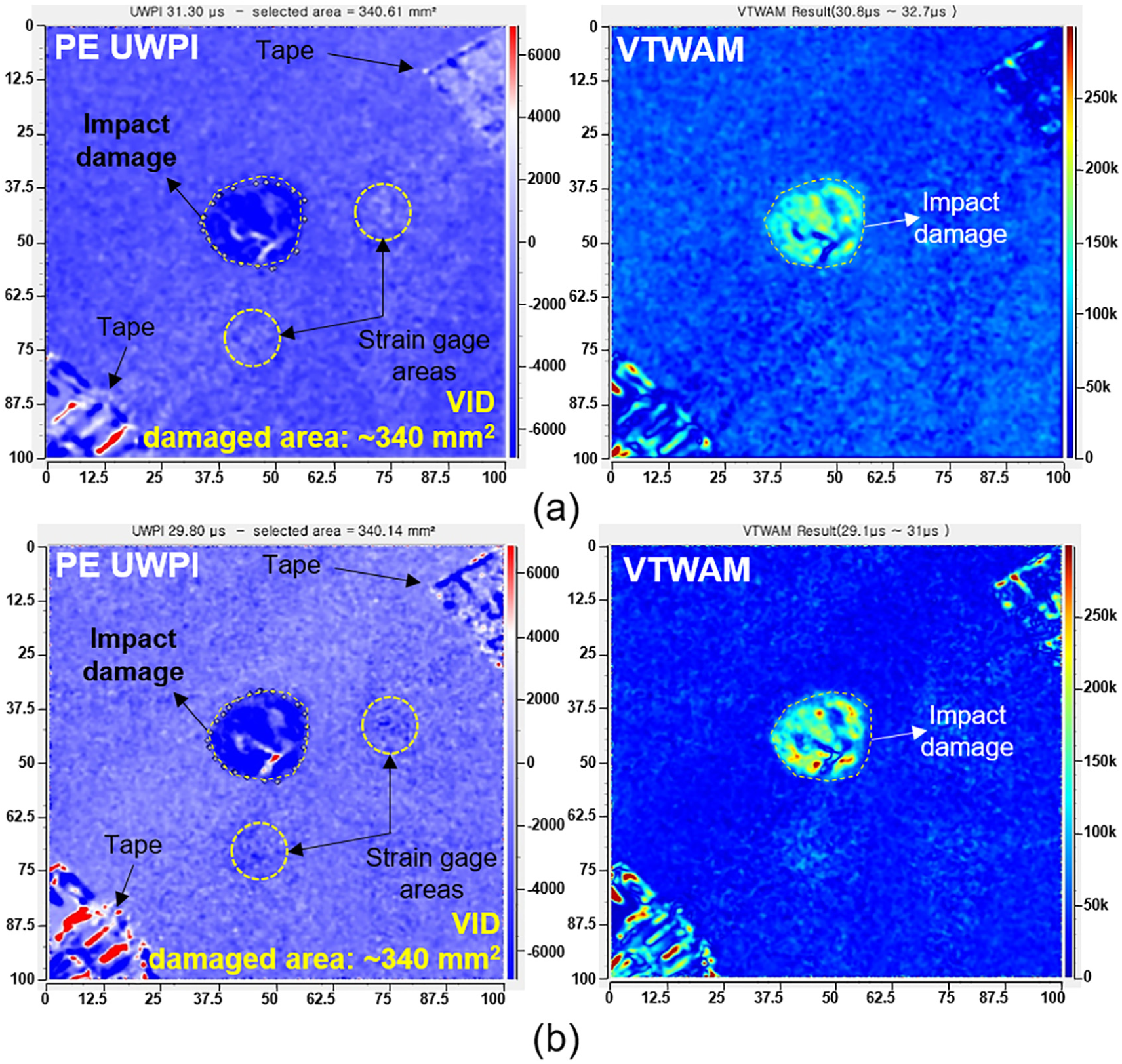
Comparison of impact damage on the sandwich skin: (a) before and (b) after the fatigue test using the inspection results of PE UWPI freeze frames and VTWAMs.
Figure 8 shows impact damage on the solid laminate skin. The outer skin shows a very small dent under the BVID level, but the visualized figure shows a large damage area in the laminate skin. The shape and direction of the damaged area were related to the fiber direction of the inner ply, which was a break. The scanning image shows the damage on the inner surface of the skin through the laminate. Figure 9 shows that there was no distinguishable growth of damage during the fatigue life test.
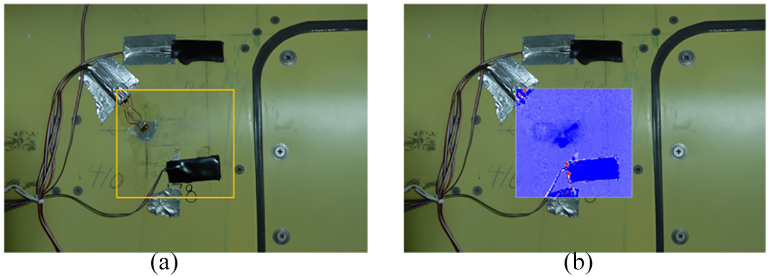
NDI and visualization of the impact damage on the solid laminate skin: (a) scan area and (b) inspection result.
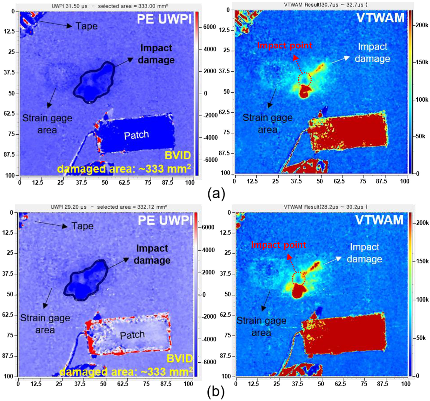
Comparison of impact damage on the solid laminate skin: (a) before and (b) after the fatigue test using the inspection results of PE UWPI freeze frames and VTWAMs.
For the test of combined damage characteristics, large impact damage (LID) was made near the BVID point on the honeycomb sandwich skin. The damage was evaluated before and after design limit load test (DLLT), and the results are shown in Figure 10.
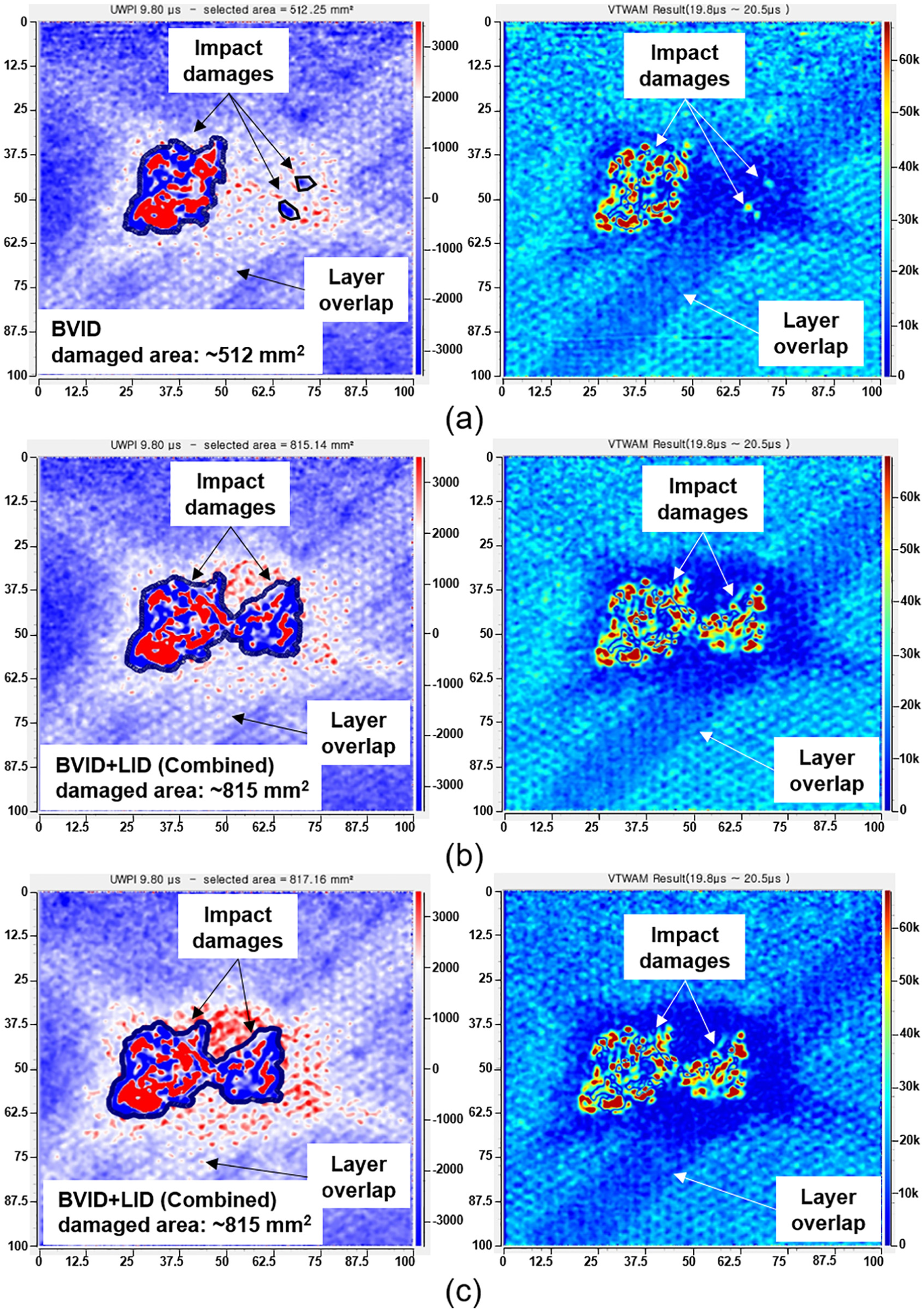
Comparison of impact damage: (a) initial damage, (b) before, and (c) after the damage limit load test using the inspection results of PE UWPI freeze frames and VTWAMs.
Figure 10(a) shows initial BVID made on the skin structure. The impact energy caused outer skin damage with a core dent, and the skin was delaminated. The diagonal white band is the overlapped region of skin ply, and the dimples are hexagonal core. Figure 10(b) shows damage combination of BVID and LID. The additional LID made a deep dent on the sandwich skin, and it also could affect the existing damage. This kind of damage also should be considered the severe case, because the combined damage area can generate unpredictable large delamination in the structure. According to comparison of the scan results, as shown in Figure 10(b) and (c), there was no distinguishable increment of the damage shape and size as a result, which means the combined impact damages and cracks meet the no-growth requirement after DLLT. This result confirms that these design damages are acceptable for the fatigue life requirement of the aircraft structure. The DULT was conducted after repairing VIDs and LIDs, and the structure met the requirement, as expected.
Damage tolerance (DT) test aims at showing no damage growth after fatigue loading. For that, indeed, we need high spatial resolution image to make sure it because the damage images before and after test must be identical to pass the DT test. In this point of view, the results presented here showed successful demonstration of the required function.
Conclusion
A full-scale composite aircraft structure was developed, and a damage tolerance test for fatigue life requirements was conducted. Based on the fatigue life test of the damaged composite specimens, the damage tolerance design margin was defined initially. After the fabrication of the aircraft structure, various impact damages were made on the composite fuselage structure, and a damage tolerance test was conducted. Basically, the damage tolerance test of the composite structure includes the DLLT and DULT after finishing fatigue cycle loading to show that the damages do not affect the structural integrity. In this study, a new and detailed in situ NDE method for the damage was proposed using the angular scan PE UPI. With the help of the angular scan PE UPI with real-time, noncontact, remote evaluation and small line-of-sight area requirement, damages and cracks could be monitored during damage tolerance tests, and both the inside and outside of the damaged skin could be identified with visualization. Furthermore, it was confirmed that the damage and cracking did not grow after the fatigue spectrum cyclic loading and DLLT, directly. By tracing the behavior of various damages in the composite structure with visualization, more detailed damage tolerance design, damage control, and certification of damage tolerance tests will be possible.
Footnotes
Declaration of conflicting interests
The author(s) declared no potential conflicts of interest with respect to the research, authorship, and/or publication of this article.
Funding
The author(s) received no financial support for the research, authorship, and/or publication of this article.
