
Abstract
The amplitude and the phase information are both important for damage localization in Lamb wave–based structural health monitoring and non-destructive testing. Most previous studies in Lamb wave imaging are only based on either the amplitude or phase of the signal at the time of flight. In this study, a post-processing technique for Lamb wave phased array imaging is proposed for isotropic plates, which simultaneously utilizes both the amplitude and phase information within a small neighborhood centered at the time of flight. In the proposed imaging algorithm, a modified virtual time reversal is firstly implemented to compensate for dispersion and the amplitude decrease caused by wave diffusion. Then the waveform covariance between any two processed wave packets, which contains information of both amplitude and phase, is used as the indicator of the presence of damage. Finally, adaptive weights based on minimum variance are introduced to weight and sum the waveform covariance for damage imaging. Based on a uniform circular array, experimental results on an aluminum plate with three defects verify that the proposed algorithm is capable of localizing multiple defects, suppressing background noise and main lobe width.
Keywords
Introduction
Lamb waves are typical ultrasonic guided waves propagating in plate-like structures and are capable of propagating long distances. It has been confirmed that Lamb waves are sensitive to both surface and internal defects, such as crack, 1 corrosion, 2 matrix cracking, 3 and delamination. 4 Lamb wave–based structural health monitoring (SHM) and non-destructive testing (NDT) methods are efficient because these methods can monitor or detect the area of the whole Lamb wave propagation path. So far, Lamb wave–based SHM and NDT have attracted much attention.
For visualizing damage intuitively, various damage imaging methods have been developed, which can be roughly divided into two categories: sparse array–based imaging methods and compact array–based methods. Usually, the compact array used is for beamforming so that it can also be seen as the phased array, and dispersion compensation is necessary because dispersion can lead to phase distortion. Multiple dispersion compensation methods, such as time-distance mapping, 5 linear mapping, 6 and warped frequency transform, 7 have been proposed. The sparse array–based imaging methods have no strict requirements on element positions, but they are usually arranged in the form of the sparse array to acquire information as much as possible from different directions and locations. It is known that the sparse array–based imaging methods include several different algorithms, such as the delay-and-sum (DAS) imaging,8–10 the minimum variance distortionless response (MVDR) imaging,11–14 the probabilistic algorithm based on signal differences,15,16 and the model-based imaging algorithms.17–19 In sparse array–based imaging, the information can be captured from multiple even all directions and the element positions in the array have no limitation. However, the sparse array–based imaging usually needs baseline subtraction as the direct arrivals are hard to isolate, while the accurate baseline data is not easy to obtain because it is sensitive to many environmental factors like temperature.
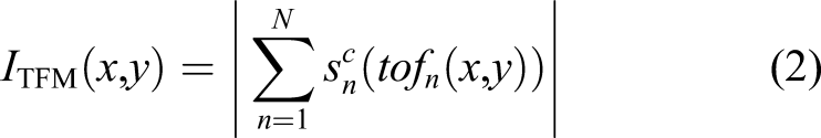
The compact array–based imaging is baseline-free and has attracted more and more attention in recent years. In the existing Lamb wave phased array–based imaging algorithms, their imaging indexes are based on either the signal amplitude or phase. For amplitude-based imaging, the total focusing method (TFM) 20 is the most famous and widely used one and sometimes is referred to as the “gold standard” among the existing imaging algorithms. 21 Liu and Giurgiutiu discussed the influence of several parameters such as wavelength, spacing, and the number of elements on the imaging performance. 22 Sternini et al. proposed a modified MVDR imaging algorithm using the updated look directions for Lamb wave phased array. 23 Yang et al. proposed a frequency response function–based TFM algorithm considering dispersion. 24 For phase-based imaging, the sign coherence factor (SCF) 25 is one of the representatives. Prado et al. used the SCF imaging result to be the weight of the TFM imaging result, 26 which can be seen as an image compounding technique. Chen et al. developed an SCF-based search algorithm for defect localization with laser generated Lamb waves, which can improve imaging quality and reduce execution time compared with the conventional SCF algorithm. 27 The multiple signals classification (MUSIC) is also widely used in Lamb wave phased array. Zuo et al. proposed an improved MUSIC imaging algorithm for composite laminates. 28 Bao et al. proposed a synthesis aperture-MUSIC imaging algorithm for complex structures. 29 The authors proposed a dispersive MUSIC algorithm, which does not need to estimate the number of eigenvalues corresponding to the noise subspace. 30 Recently, Yang et al. expanded the conventional MUSIC from phased array to arbitrary array 31 and from the time domain to the frequency domain, 32 respectively. Although the MUSIC algorithm can achieve damage imaging using Lamb waves, the dynamic range is small in the imaging results. Furthermore, the MUSIC algorithm is based on harmonic waves and very sensitive to the phase difference, which makes it is not so robust to noise or interference.
Since both signal amplitude and phase are important for damage imaging, it is reasonable to consider that it would achieve better imaging performance if one algorithm makes full use of the two factors simultaneously. Presented here is a damage imaging algorithm for Lamb wave phased array, which considers and utilizes the two factors simultaneously. To compensate for the amplitude decrease caused by wave diffusion and dispersion, a modified virtual time reversal technique is used to process the collected signals. An imaging index based on waveform covariance between any two processed wave packets is defined and the MVDR algorithm is introduced to further suppress background noise.
The remainder of this paper is organized as follows. The conventional TFM and SCF algorithms are briefly reviewed in the Brief Review of Conventional TFM and SCF Algorithms section. The methodology of the proposed algorithm is presented in detail in the Methodology section. Experiments are conducted for validation in the Experimental Validation section. Discussion on the influence of two parameters on imaging results is given in the Discussion section. Finally, the conclusion is drawn in the Conclusion section.
Brief review of conventional total focusing method and sign coherence factor algorithms
For Lamb wave phased arrays, the TFM and SCF are two representative imaging algorithms based on the signal amplitude and phase, respectively. In both two algorithms, dispersion should be compensated firstly before imaging for the total of N collected signals, namely

Different from the TFM algorithm, the SCF algorithm utilizes the phase coherence among the N dispersion compensated signals but not the corresponding amplitudes. The imaging index at the imaging point
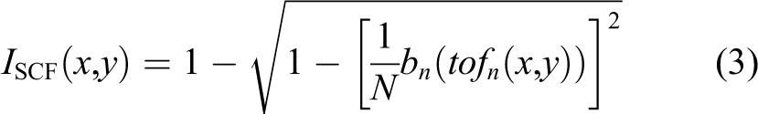
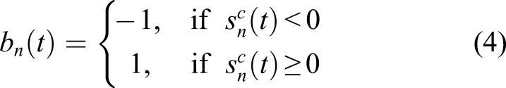
The signal amplitude and phase information are both important and useful for damage imaging, which should be utilized as much as possible to achieve better imaging performance. It can be seen that the SCF measures the polarity (positive or negative) coherence of the dispersion compensated signals at the time of flight, and the TFM measures the absolute value of the sum of the dispersion compensated signal amplitudes at the time of flight. The two imaging algorithms utilize only either the amplitude or phase at a single point (only the information at the time of flight is utilized), which limits their imaging performance.
Methodology
Influence of dispersion on Lamb waves
Dispersion is an inherent characteristic of Lamb waves, which is also one of the main differences between Lamb waves and bulk waves. Under the excitation of amplitude modulated harmonic signal with a narrow bandwidth, the response signal at the point
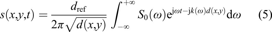
Because of the nonlinear relation between
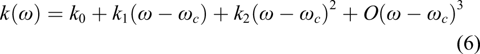
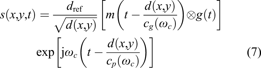
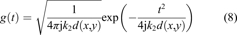
As can be seen from equation (7), compared with the excitation signal, there is an amplitude decrease caused by wave diffusion, a time-shift equaling
Modified virtual time reversal
Considering the case where only a single point-like scatterer located in the position
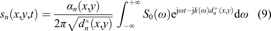
To implement signal focusing, it is necessary to remove the distorted wave packets of the received signals caused by dispersion. Time reversal is an effective strategy that can remove the dispersion effect and can be virtually implemented using the transfer function.33–35 In this study, as the transfer function from the transmitter to the point

If the signal


It can be seen from equations (12) and (13) that the scattering information contained in the backpropagated signal holds the same waveform as that of the excitation signal, and the amplitude decrease caused by wave diffusion and the phase-shift caused by dispersion are both compensated. Therefore, the conventional signal focusing rules can be directly used for the backpropagated signals.
Waveform covariance
After the implementation of the modified virtual time reversal technique for all the N received signals, waveform covariance imaging (WCI) is proposed for damage localization. The covariance between any two backpropagated signals with the specific time range is calculated, namely
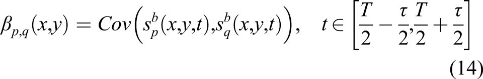
The covariance
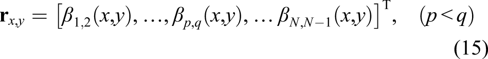
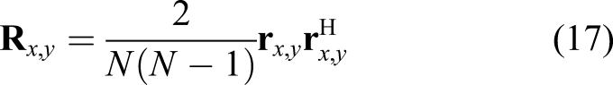
To define the imaging index, a vector consisting of all the

The optimal weight vector can be calculated by solving the following constrained optimization problem


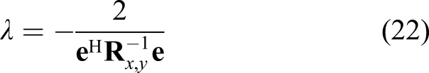
Equation (18) can be solved by the use of a Lagrange multiplier

Minimizing the Lagrangian by forcing its derivative with respect to
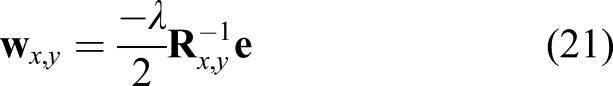
Taking use of the inner product of
Substituting equation (22) into equation (21), the closed-form expression of
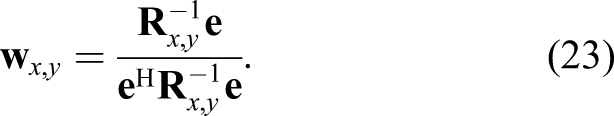
To avoid the ill-pose problem in the calculation of the matrix inverse in equation (23), the diagonal loading is usually taken using a regularization parameter ƒ

In summary, at each imaging point, the proposed WCI imaging algorithm firstly backpropagates the received signals from the corresponding receiver to the imaging point and then to the transmitter through the modified virtual time reversal, and then calculates the covariance values between any two backpropagated wave packets, and finally combines all the covariance values using the adaptive weights based on the MVDR. The main steps of the proposed WCI imaging algorithm are schematically shown in Figure 1. The main steps of the proposed WCI imaging algorithm.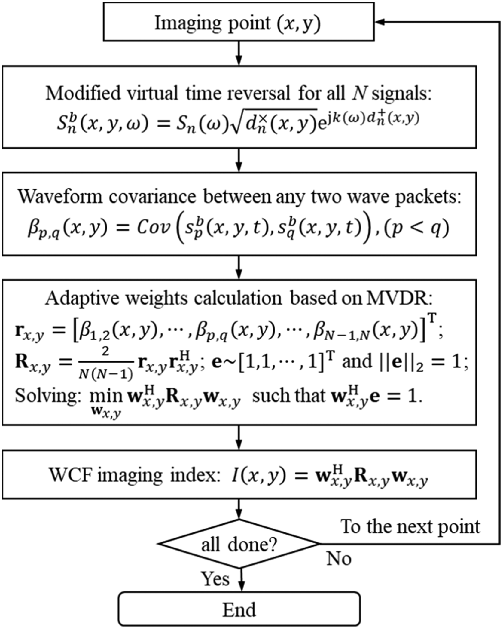
Experimental validation
Experimental setup
To verify the feasibility of the proposed WCI algorithm, experiments on an isotropic aluminum plate are implemented. The specimen is a 2-mm thickness aluminum plate, where a uniform circular array (the radius of the circular array is 15 mm) consisting of 8 PZTs (0.5 mm in thickness and 8 mm diameter) are glued upon the plate. The excitation signal is selected to be a Hanning windowed 5-cycle tone burst centered at 80 kHz. Under such an excitation signal, the A0 mode becomes the dominant mode in the response signals. Three defects including one through-hole and two surface defects (simulated by PZTs glued upon the surface of the plate) are introduced successively. The size of the plate, the location of the array, and the locations of the defects are shown in Figure 2. The specimen is an aluminum plate of 2-mm thickness with a uniform circular array consisting of 8 PZTs: (a) Schematic of the plate and (b) photograph of the plate. Three defects are introduced: defect a is a through-hole, and defects b and c are simulated by PZTs glued upon the plate.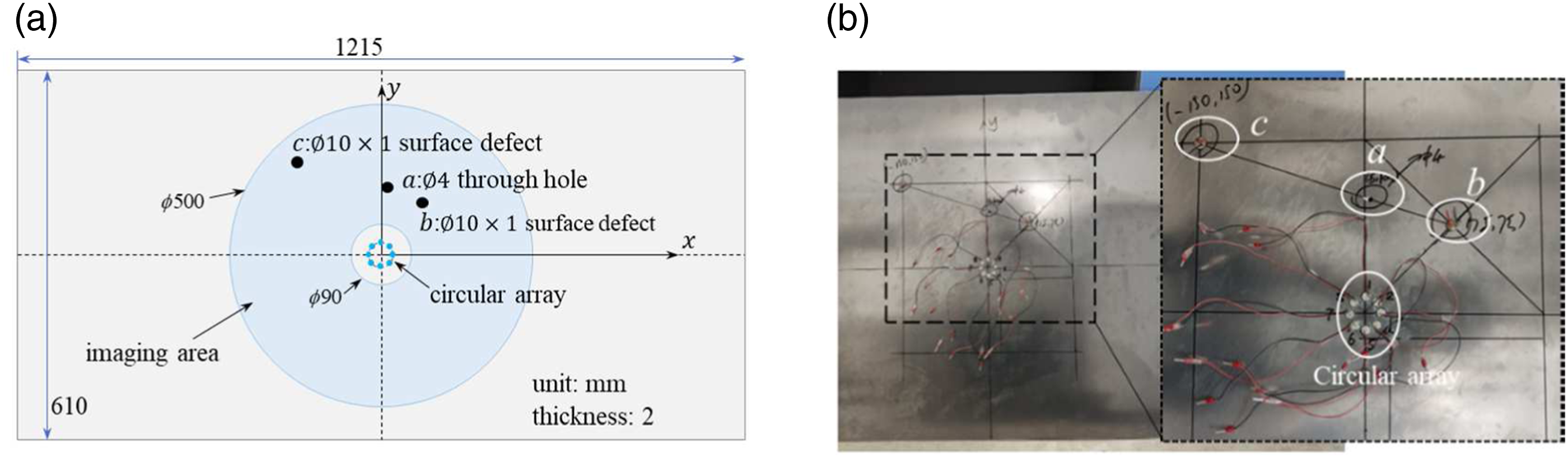
The signal acquisition strategy is based on a round-robin fashion: every element of the array serves as the transmitter in turn, and the rest serve as the receivers. Under such a fashion, a total of 56 signals are collected in each experiment. Signals are firstly collected when there is only a through-hole (defect a), and another set of signals is also collected after the two surface defects are introduced. The sampling frequency is set to be 10 MHz and the time length is 0.8 ms. In both experiments, signals are measured 128 times and then the corresponding averages are used to improve the signal-to-noise ratio. The collected signals under the case of only a through-hole existing on the plate are shown in Figure 3. Considering the reciprocity, only half of the 56 signals are used for imaging. It should be noted that the baseline data are not required in this study. To isolate the direct arrivals and the edge reflections, only the region between the two circles is selected to be the imaging area, as shown in the highlighted area in Figure 2(a). Waterfall view of the 56 signals received when there is only the defect a on the specimen.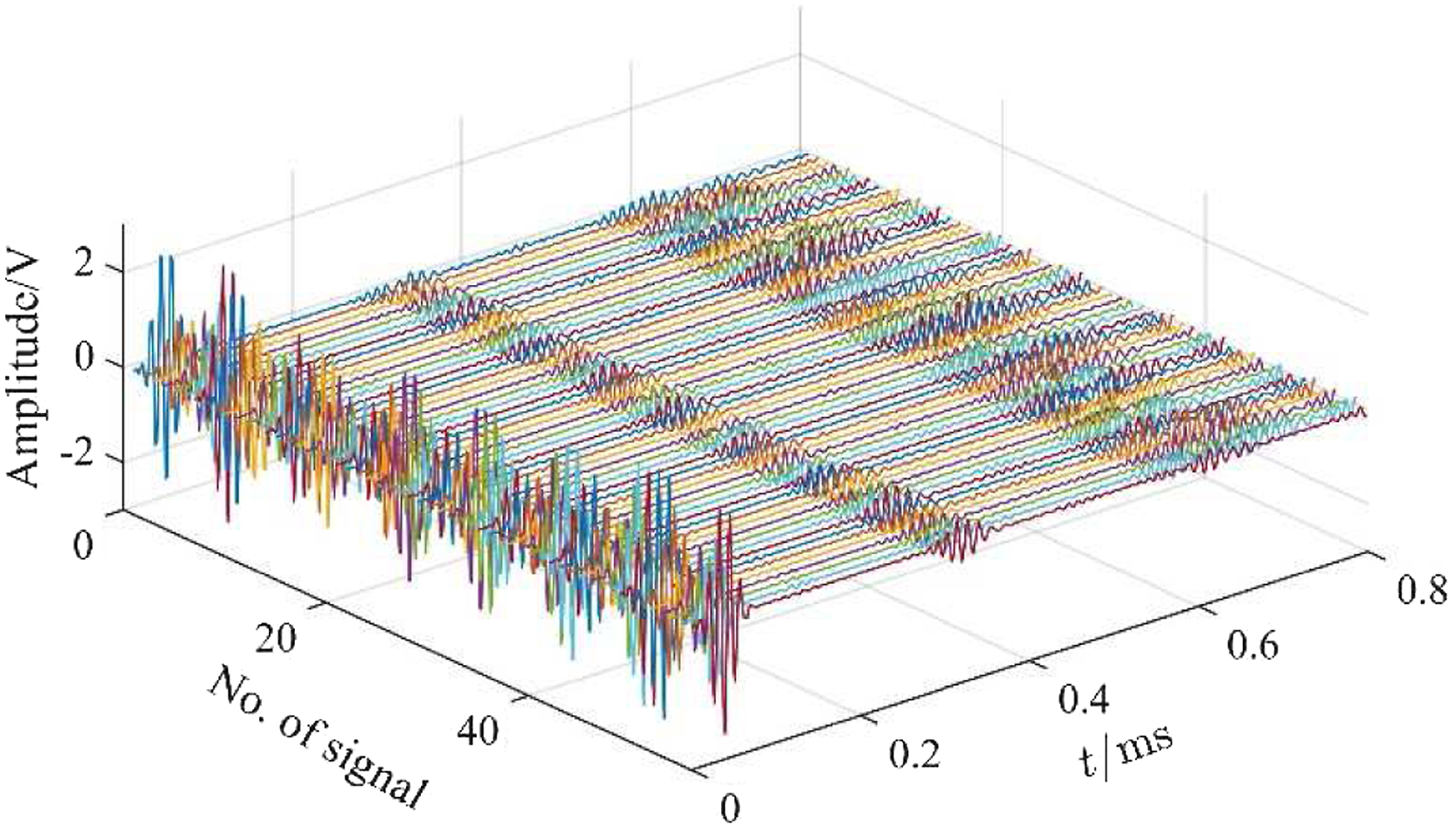
Results
To generate imaging results, the imaging area is discretized into grids with the size of 2 mm

Single defect
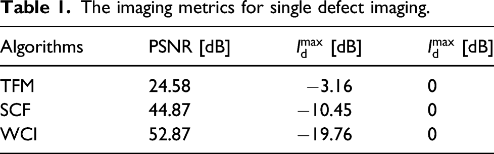
The case of a single defect is firstly investigated. The imaging results via the TFM, the SCF, and the proposed WCI algorithms are shown in Figure 4(a)–(c), respectively. All imaging values are processed with a logarithm and all the images are displayed on a 40 dB scale. In these images, the white dots represent the elements of the array, and the black circle denotes the actual location of the defect. From the three images, it can be seen that all three algorithms can correctly locate the defect, while the TFM image holds the most artifacts and the proposed WCI image has almost no artifacts on the displayed scale. The corresponding imaging performance metrics listed in Table 1 confirm that the proposed WCI outperforms the other two algorithms. The maximum value of the background noise in the TFM image is only about 3 dB smaller than that of the actual defect, while the corresponding value in the WCI image is about 19 dB. Furthermore, the PSNR in the proposed WCI image is also improved compared with that in the TFM and SCF images. It should be noted that in the calculation of imaging performance metrics, the defect area is defined to be a circular area with a radius of 20 mm centered on the actual defect center, and the rest of the imaging area is the area of the background. Imaging results for single defect via three different algorithms: (a) TFM; (b) SCF; and (c) WCI. The black circle denotes the location of the actual defect, and the white dots denote the elements of the circular array. The imaging metrics for single defect imaging.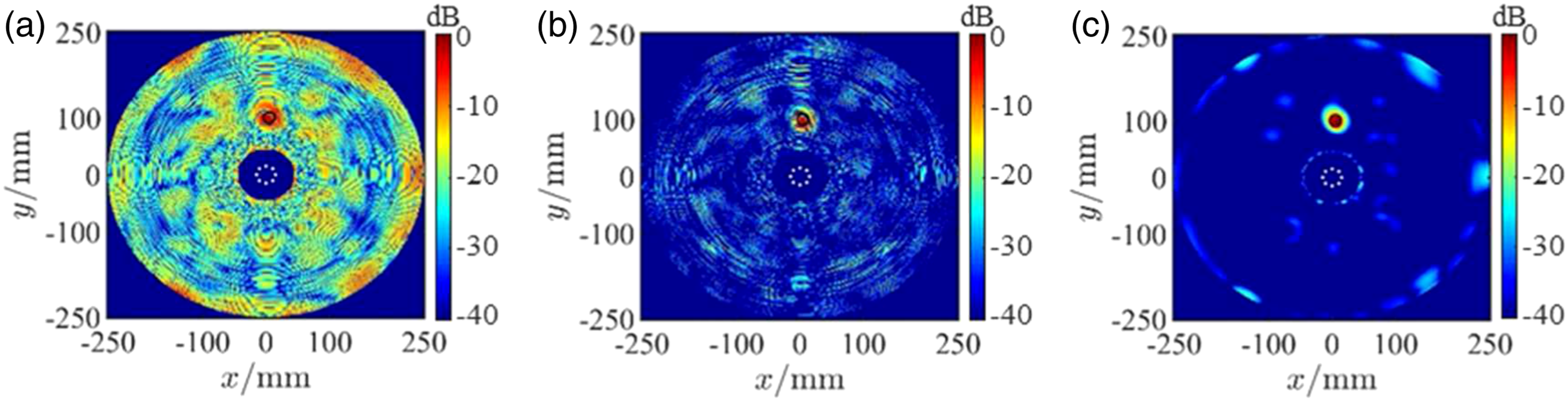
The lateral views along the horizontal and the vertical lines for the defect in the three imaging results are extracted and shown on an 80 dB scale in Figure 5(a) and (b), respectively. From the comparison, it can be seen that the lateral views of the WCI image hold the narrowest main lobe and lowest background noise in both horizontal and vertical lines. The narrower the main lobe and the lower the background noise both mean better imaging performance. It can also be seen from the two lateral views that the imaging results of the TFM and the SCF oscillate with the change of position, especially for the SCF. This is because the TFM and the SCF algorithms only consider the single point of the signal at the corresponding time of flight, which will make the two algorithms sensitive to signal noise and interference and therefore reduce the robustness. As can be seen from equation (14), the proposed WCI algorithm considers both signal amplitude and waveform coherence within a small neighborhood centered at the time of flight so that the imaging performance improves. Lateral views for the defect a in the three imaging results: (a) view along with y=100 mm and (b) view along with x = 5 mm. The blue dash-dotted line denotes the actual location of the defect.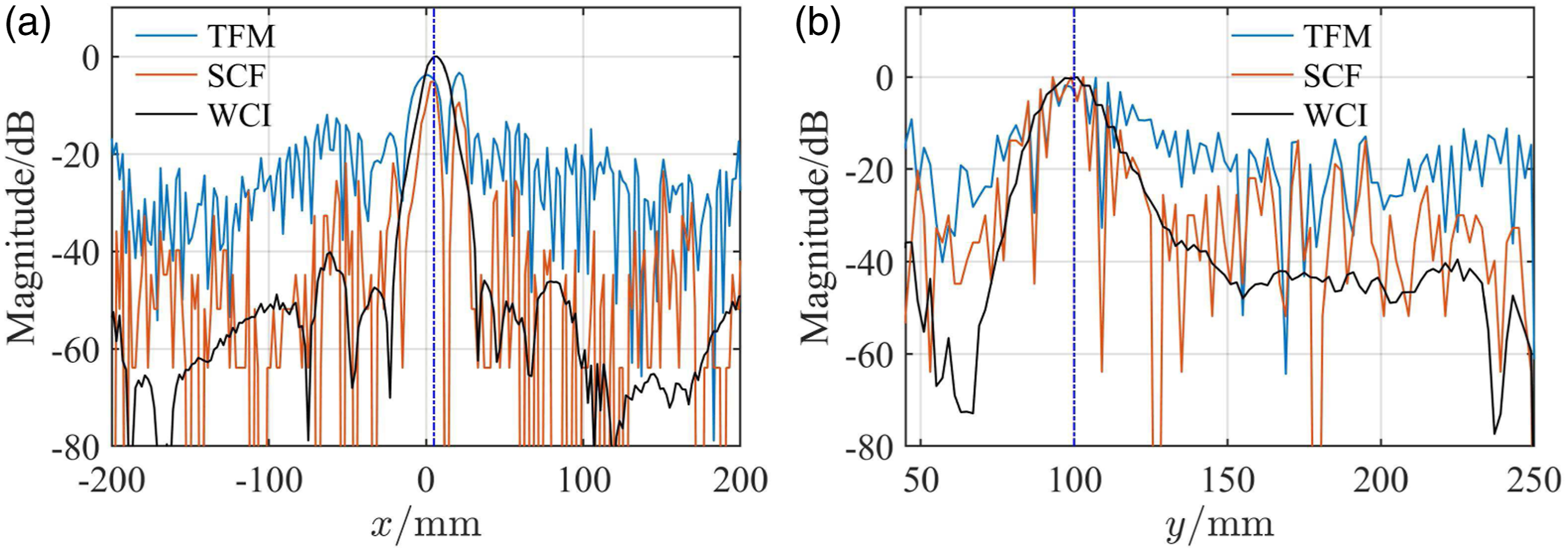
Multiple defects
The capability of imaging multiple defects in the imaging area is also investigated. The imaging results via the three imaging algorithms for all the three defects are shown in Figure 6(a)–(c), respectively. It can be seen that all three algorithms can locate the three defects, and the WCI image holds the fewest artifacts on the displayed scale and the lowest background noise. The imaging results for both single and three defects show that the proposed WCI algorithm outperforms the TFM and the SCF algorithms. Imaging results for three defects via three different algorithms: (a) TFM; (b) SCF; and (c) WCI. The black circles denote the locations of the real defects, and the white dots denote the elements of the circular array.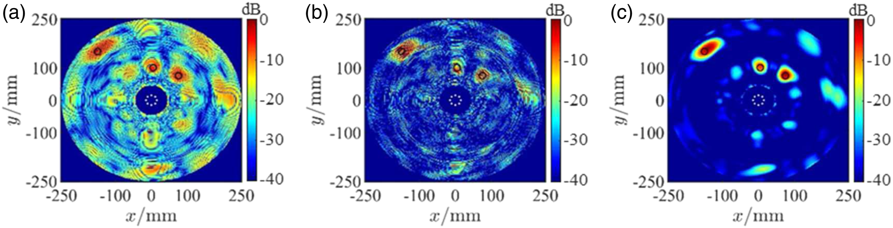
Discussion
The above results of the proposed WCI algorithm are all based on the parameters given as:
The influence of the parameter τ
As mentioned in the Methodology section, the parameter Imaging results via the WCI algorithm under different parameter Lateral views for the defect a in the imaging results under the case of three defects using different 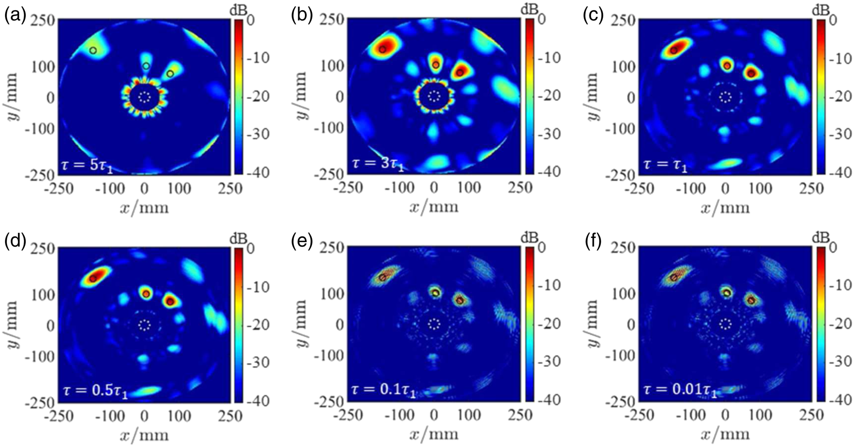
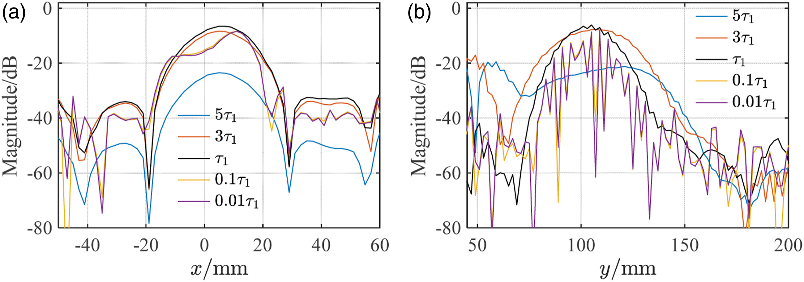
It can also be seen that when
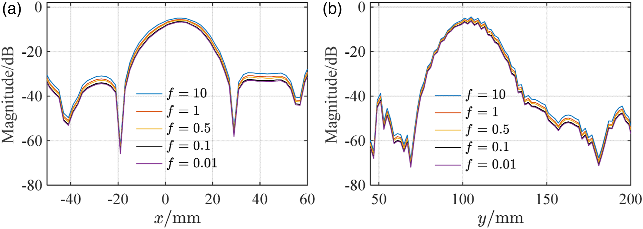
The influence of the regularization parameter ƒ
The influence of the regularization parameter on imaging results is also investigated. The larger the parameter Lateral views for the defect a in the imaging results under the case of three defects using different regularization f: (a) view along with y = 100 mm and (b) view along with x = 5 mm. The parameter τ = τ
1
.
Conclusion
In conventional signal amplitude and phase coherence–based imaging algorithms for Lamb wave phased arrays, the imaging performance is limited because only signal amplitude or phase information at the time of flight is utilized. Aimed at improving imaging performance, a WCI algorithm is proposed in this study. The signal amplitude decrease caused by wave diffusion and dispersion is simultaneously compensated through the modified virtual time reversal technique. The WCI, which is based on waveform covariance between any two amplitude and dispersion compensated signals, is defined and used as the damage index for imaging. Because both signal amplitude and waveform coherence contribute to waveform covariance, the defined WCI utilizes more information than the conventional TFM and SCF algorithms. The experimental results show that compared with the conventional TFM and SCF algorithms, the proposed WCI algorithm is capable of improving imaging performance (lower artifacts and background noise, narrower main lobe). The proposed WCI algorithm could be a potential or alternative choice of the signal post-processing for Lamb wave phased arrays.
Footnotes
Declaration of conflicting interests
The author(s) declared no potential conflicts of interest with respect to the research, authorship, and/or publication of this article.
.
Funding
The author(s) disclosed receipt of the following financial support for the research, authorship, and/or publication of this article: This work was supported by the National Natural Science Foundation of China (Grant Nos. 12134002, 52005058, 12074050, and 11834008), the Fund for Innovative Research Groups of Natural Science Foundation of Hebei Province, China (Grant No. A2020202002), the China Postdoctoral Science Foundation (Grant No. 2020M673119), and the Young Elite Scientists Sponsorship Program by CAST (Grant No. 2021QNRC001).