
Abstract
Precise damage identification and quantification is of great significance to ensure structural performance and provide early-warning for safety maintenance. In this research, a time-reversal assisted probabilistic strategy is developed to accurately localize damage via baseline-free manner in plate-like structures by fusing damage prediction data obtained from the elliptical trajectory location method (ETLM) and reconstruction algorithm for probabilistic inspection of defects (RAPID) algorithm. Damage features, including time difference for ETLM and correlation coefficient index (CCI) for RAPID algorithm, are extracted from the time-reversal focusing signal using the Hilbert transform (HT). To make full use of the damage-related information contained in the time-reversal focusing signals and improve the localizing accuracy, a decision-level data fusion based on Bayesian inference is proposed to fuse damage features and reconstruct damage information. A series of numerical and experimental studies, including different configurations of damage cases and transducer distributions, were conducted to investigate the performances of the proposed time-reversal assisted probabilistic method on damage localization. Results shows that the proposed method could successfully achieve accurate damage localization via baseline-free manner and significantly reduce the damage artifacts compared to traditional methods.
Keywords
Introduction
In recent years, the development of structural health monitoring (SHM) technologies has attracted much attention in both laboratory research and field applications. 1 Guided-waves (GWs), as one of the active damage detection methods, can provide quantitative damage information within seconds.2,3 Among GWs, Lamb wave detection technology has many advantages, including a wide inspection range, high sensitivity to incipient damage and low cost,4–6 which makes it a promising approach for online SHM system applications. A large number of theoretical and experimental studies have been conducted to verify the feasibility of Lamb waves on the damage detection and evaluation field.7–11 The structural conditions can be evaluated by extracting damage-related characteristics of Lamb waves.12,13 The Lamb waves-based damage detection and quantification could be divided into the baseline method and baseline-free method. 14 Baseline methods, which compare the signals from the intact state and damaged state to obtain damage indexes, have good robustness for structural condition evaluation. However, baseline signals are typically difficult to be obtained in field applications. The baseline-free method, circumventing the difficulties of baseline signal acquisition via various methods,15–19 has drawn much attention in SHM.
Among them, the time-reversal method, a baseline-free method proposed by Ing and Fink, 20 has been extensively adopted in structural damage detection 21 and condition monitoring 22 because the dispersive characteristics of Lamb waves are significantly compensated and the subsequent analysis is simplified. The philosophy of time-reversal method is based on the reciprocity of acoustic waves, which means that the input signal can be well reconstructed at the location of the actuator if the medium is intact. The differences between the reconstructed signal and the original input signal may indicate the occurrence of defects. The simple interpretation of time-reversal focusing signals leads to the extensive application of the time-reversal method on SHM.
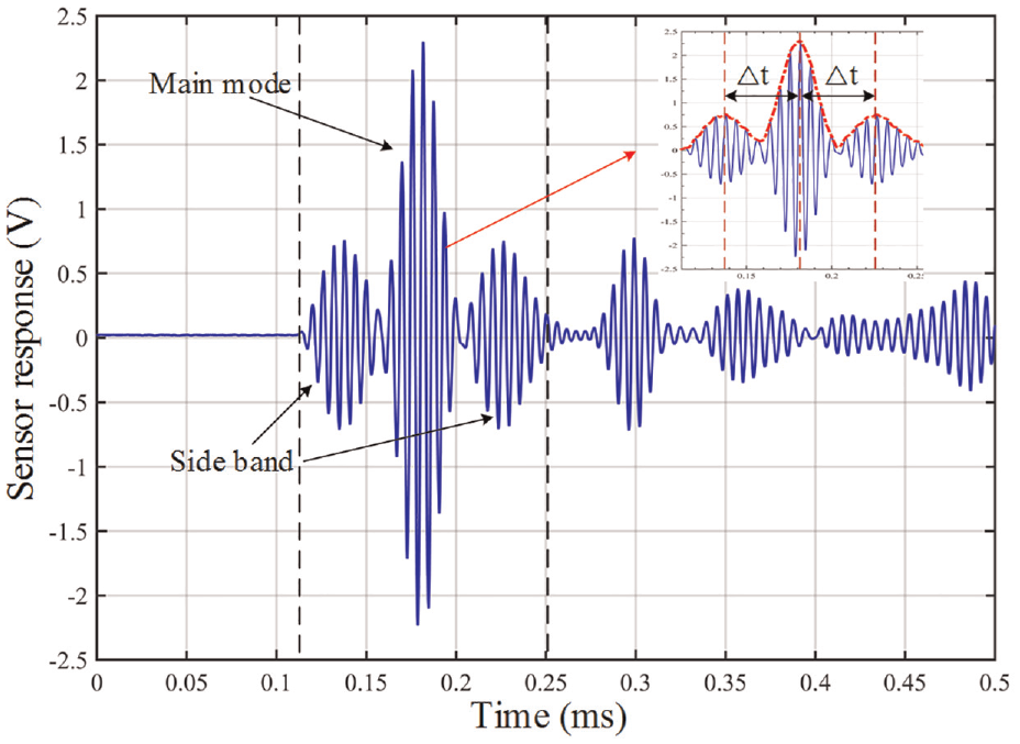
The time-reversal focusing signal mainly consists of two parts, namely, the main lobe and the sidebands. 23 The main lobe is produced by the focusing of the direct propagating waves, while the sidebands are generated by the damage-induced scattering waves. It has been proved that the scattered waves contained the rich information about the damage.24,25 The time differences of the damage induced scattered waves are contained in the sidebands, which could be utilized for damage localization.26–28 It is interesting to cooperate the elliptical trajectory location method (ETLM) with the time differences obtained from the time reversal method to achieve baseline-free damage localization.
Another widely used damage index of time-reversal focusing signals is the correlation coefficient index (CCI) between the reconstructed signal and original input signal. The CCI has been widely used in damage detection 29 and condition monitoring of concrete structures, 30 bolt connections, 31 and plate-like structures. 32 A pioneering study is conducted by Wang 33 to combine the CCI of time-reversal signals and a reconstructed algorithm for the probabilistic inspection of damage (RAPID) method to localize the defects in composite structures to circumvent the difficulties of complicated data analysis procedures of Lamb waves induced by anisotropy of composite structures. In RAPID algorithm, the damage index and spatial probability distribution function are used to characterize the damage, and a weighted superposition of the damage indexes of each path gives the amplitude of the imaging points. It needs to be noted that the CCI is sufficient to function as a damage indictor but suffers from poor time-resolution. Then, Wang et al. 9 used CCI and RAPID to localize defect in aluminum plate and utilized virtual sensing paths to enhance the performance of this approach. After that, Miao et al. 34 calculated the CCI via time-reversal reconstructed waveform, and the CCI was utilized as an input damage feature for RAPID algorithm to localize damage. As the damage size changes, the CCI calculated by the traditional main wave packet of the time-reversal focusing signal could not perform sufficient sensitivity to damage. Agrahari and Kapuria et al. 29 proposed a new approach to calculate the CCI based on the extended wave packet, and this damage feature showed excellent sensitivity to damage when it is utilized at the best reconstructed frequency. For different forms of damage, the CCI based on the extended wave packet could exhibit good performance. 35 Some influential factors (such as: adhesive layer, the thickness of host structure, excitation signal and ambient temperature, etc.) have been considered to investigate the effects on CCI.22,36 Further, a significant application has been made to fully explore and enhance the combination of CCI based on the reconstructed signal and RAPID algorithm to achieve accurate damage localization. 37 Moreover, to eliminate the need of two measurements for each sensing path, the virtual time reversal (VTR) method 38 is utilized to improve the efficiency of obtaining CCI, and considerable efforts have been devoted to investigate the combination of CCI based on time-reversal focusing signals and the RAPID algorithm to different application scenarios.39–41
However, neither of the two aforementioned damage localization methods combined with time-reversal operation can fully exploit the abundant information in the focusing signals. In terms of hardware deployment, both two methods require a sensor network to accurately locate the defects. And it will lead to inadequate utilization of the established sensor network if only one of them is utilized to locate damages. In order to circumvent obstacles, probabilistic method is used to reduce errors and improve accuracy.42,43 To define the field value of image pixel via probability method, Zhou et al. 44 proposed a novel probability-based diagnostic method for damage localization with hybrid signal features. Cao et al. 45 proposed a probability weighted four-point arc algorithm for damage imaging. Guo et al. 46 used matching pursuit decomposition algorithm to extract damage feature (time-of-flight) and a Gaussian kernel probability density distribution was adopted to characterize the damage.
On the other hand, Data fusion, 47 a multifaceted process of combining information from different sources, could contribute to a more precise characterization of the inspection items if appropriate data fusion algorithm was employed. Data fusion could be conducted at three levels, including the signal/data level, feature level, and decision level.48–50 Decision-level data fusion integrates decisions from different sources, which is in an analogous fashion to the decision-making process of human beings. It has been extensively applied in medical image fusion, target recognition in automatic driving and SHM. 51 It integrates different symbols with their uncertainties to generate a combination decision during the decision-making process. Among them, Bayesian inference is the process of fitting the specific probability model to the required data, uses prior information to estimate and update the posterior probability and provides supporting evidence for events. 52 With the change of evidence, Bayesian inference constantly modifies the brief degree of the hypothetical event by modifying the perceptions of numerous sensors in the sensor network. Probabilistic description provided by Bayes method allows us to consider the various uncertainties in the damage detection process, which is exactly suitable for decision-level data fusion.53,54 Therefore, the core idea is to use Bayesian inference method to integrate damage features diagnosed by the ETLM and RAPID algorithm for accurate damage localization determination in plate-like structures.
In this paper, a time-reversal assisted probabilistic fusion strategy is established based on Bayesian framework for accurate damage localization using damage features including
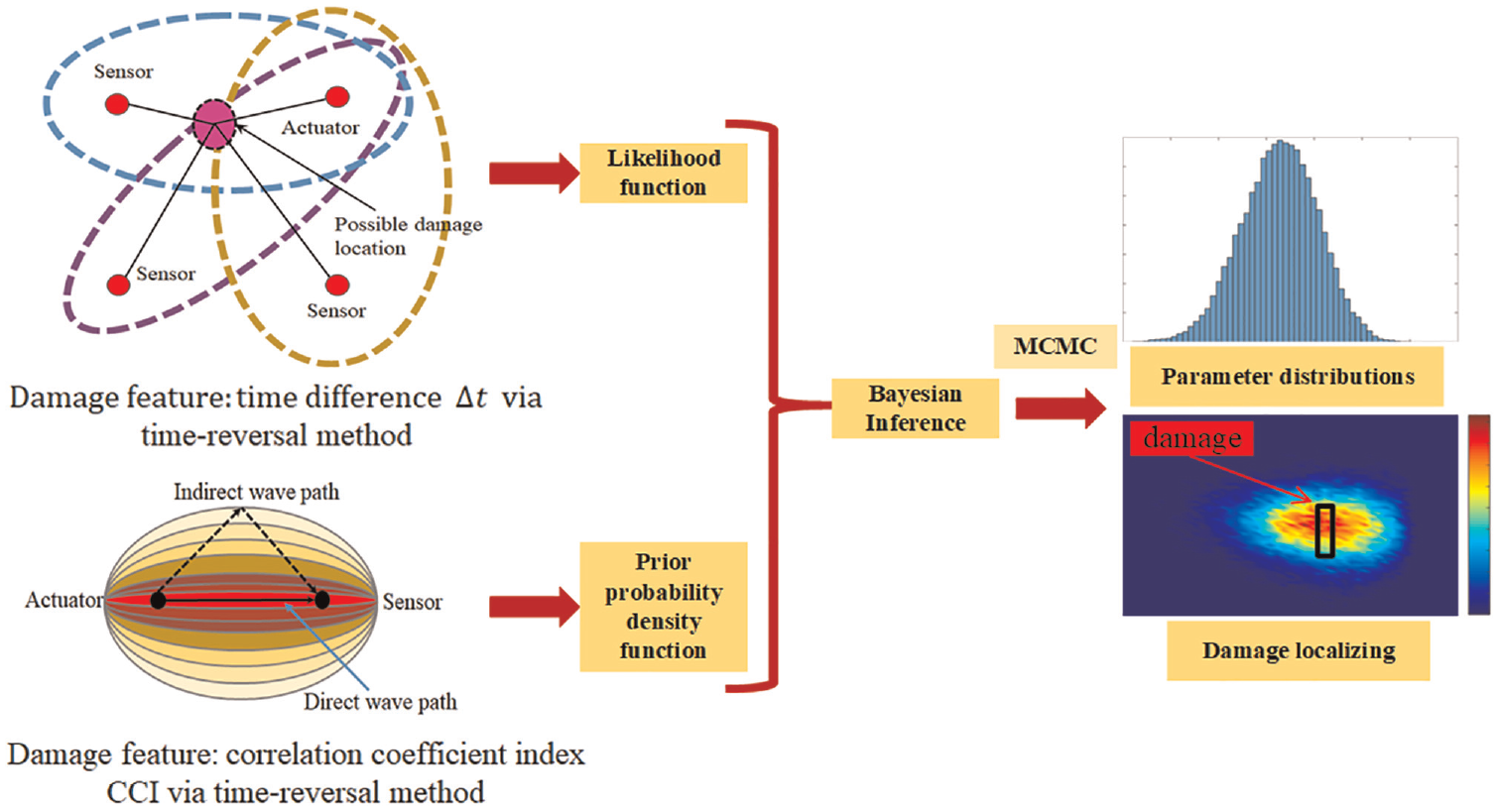
Flow chart of the proposed time-reversal assisted probabilistic fusion approach.
Methodology
Time-reversal process of Lamb waves in plate structure
The working principle of time-reversal method for damage detection is based on acoustic reciprocity. A probing signal can be well reconstructed at the location of piezoelectric actuator (lead zirconate titanate, denoted as PZT-A) when an output signal recorded at the piezoelectric sensor (denoted as PZT-S) is reversed in time domain and reemitted to the original PZT-A if the medium is intact. The time reversal operation could also realize adaptive focusing and dispersion compensation of Lamb wave signals.
In general, the time reversal process could be divided into two processes, namely the forward process and the backward process, as shown in Figure 2. In order to reduce the complexity of signal processing and calculate the damage index efficiently in the following section, the mainly antisymmetric mode (A mode) is adopted in the forward process. The received signal of the sensor in forward process contains the waves of direct path and scattered path, as shown in Figure 2(a). It needs to be noted that the damage information is mainly incorporated in the scattered wave packets. Then, the received signal including both direct wave packets and scattered wave packets is reversed in time domain and reemitted to the PZT-S in the backward process, as shown in Figure 2(a). Therefore, there are also two possible propagation paths for the reversed signal, the direct wave packets result in the main lobe of the reconstructed signal while the scattered wave packets produce the side lobe in the reconstructed signal. The reconstructed signal
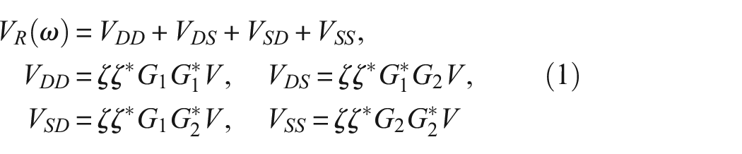
where, subscripts D and S represent direct wave path and scattered wave path, respectively. The
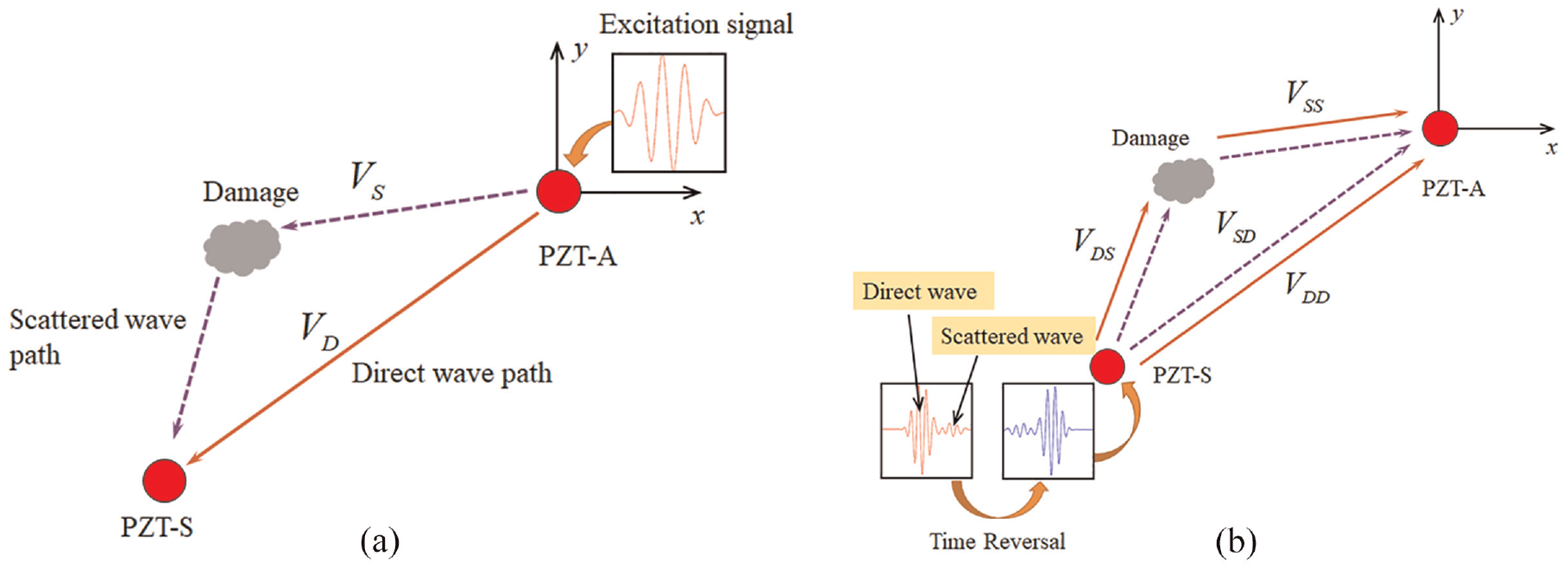
Lamb wave propagation in a plate containing a damage. (a) Forward propagating wave from actuator to sensor and(b) backward propagating from sensor after time-reversal to actuator.
By taking inverse Fourier transform of the reconstructed signal
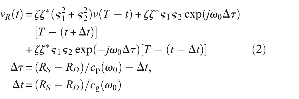
where,
Damage features extraction
Figure 3 shows a typical time-reversal reconstruction signal. The main mode is the time-reversal signal of the excitation signal, which contains only the amplitude term and is independent of the wavenumber. The other two parts appearing symmetrically on both sides of the main mode are side-lobe signals. The time difference
Schematic of time-reversal damage information extraction.
According to the acoustic reciprocity, the damage could also be evaluated by comparing the reconstructed signal with the pristine input signal in the time-reversal method. The degree of damage is assessed by the difference between the excitation signal
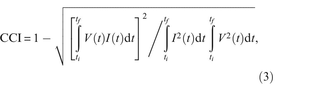
The CCI ranges from 0 to 1. A CCI closing to zero, implies that the reconstructed signal coincides well with the pristine input signal, which indicates almost no damage in the wave propagation paths. On the contrary, a high CCI value implies a significant difference between the two signals and the presence of defects in the wave propagation paths.
In the conventional time-reversal method, the CCI is calculated by using the main lobe of the time-reversal reconstructed signal. Nevertheless, with the damage size varying, the CCI calculated by the traditional main wave packet of the time-reversal focusing signal could not perform sufficient sensitivity to damage. Therefore, to increase the sensitivity of the defect indicators, a refined time-reversal method35,37 is utilized, which uses an extended wave packet ranging between the two side bands to calculate CCI to realize damage localization. In this research, the side bands and main mode contained in the reconstructed signals are utilized to calculate CCI, the start and end times of the extended wave packet are expressed as:

where
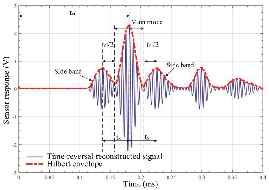
Schematic of reconstructed signal for the calculation of CCI.
Time-difference-based ETLM
The ETLM uses a series of ellipse loci with actuator and sensor being two loci, indicating the possible damage locations. Considering a sensor configuration with N sensing paths, assume the velocity
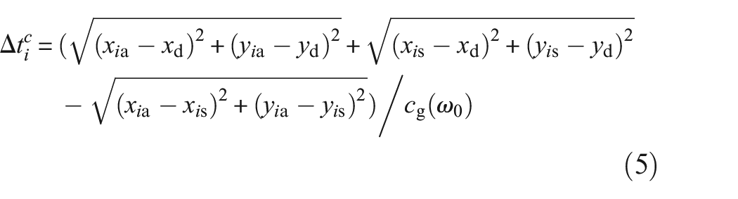
where
In order to realize probabilistic damage localizing via ETLM, the plate-like structure surface under inspection is meshed into
where
Correlation-coefficient-index-based RAPID algorithm
Inspired by computerized tomography, Hay et al. 58 applied a localizing algorithm (RAPID) to map the damage index to a single pitch-catch path of the inspection region, and used the sensor network to realize the localization. The philosophy of RAPID is based on the simple assumption that the damage on the direct path between the actuator and transducer can produce the most significant signal changes, and the degree of the signal difference will decrease with the increase of distance from the direct paths. To quantify the effects of the defects on the sensing paths, the spatial probability distribution function is introduced as the path weight function. It is assumed that the influence is a linearly decreasing elliptic distribution, where the positions of the corresponding actuator and sensor are the foci (as shown in Figure 5).
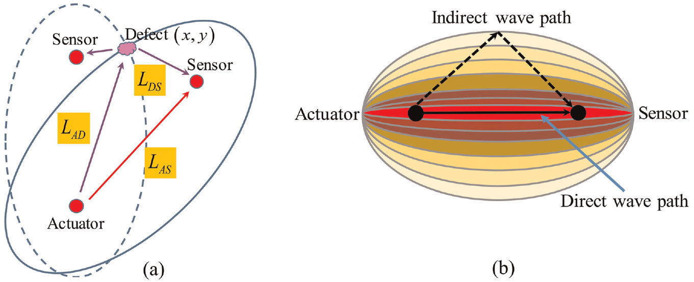
(a) Relative distance of damage location and (b) elliptical distribution function of the RAPID algorithm.
In the present study, the RAPID algorithm integrates the CCI of a single sensing path into all sensing paths covered by the detection area, and calculates the damage probability of a single grid point. Thus, the detection area is meshed into uniformly distributed grids. The probability of the defect being located at position
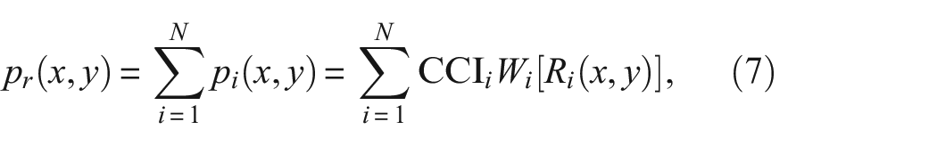
where N is the total number of paths,

where
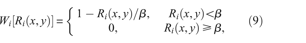
The parameter
Bayesian framework-based probabilistic fusion damage localization
Owing to the measurement errors and environmental uncertainties, the damage localization results may deviate from the actual situations. In the Bayesian inference method, the uncertain parameters can be quantified by probability distributions, which was utilized to fuse damage prediction data from the ETLM and RAPID for accurate damage localization. Specifically speaking, Bayesian framework could consider both direct or indirect measured data as evidences to evaluate these distributions of the parameter space, which makes it attract much attention in structure damage identification.59–62 Bayesian approach could not only offer statistical explanations for measurement errors and uncertainties, but also quantify these deficiencies of the inference via expectations of the parameter probability distributions.
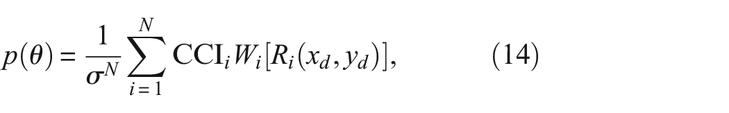
Based on this concept, the core idea is using Bayesian posterior distribution to quantify the uncertainty in damage localizing. In this research, the prior damage location information is derived from RAPID algorithm. The likelihood function is established by weighing the deviation between the measured time difference and the theoretically calculated time difference based on the ETLM. In order to quantify the uncertainty, the variable describing the deviation of the time difference

where
where the
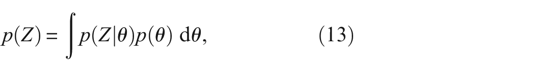
According to Bayes’ theorem, the parameter vector of the posterior probability density function (PDF) is expressed as:

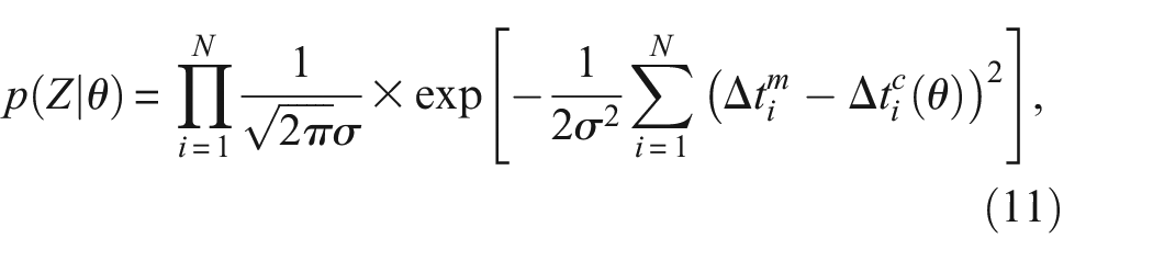
where
where
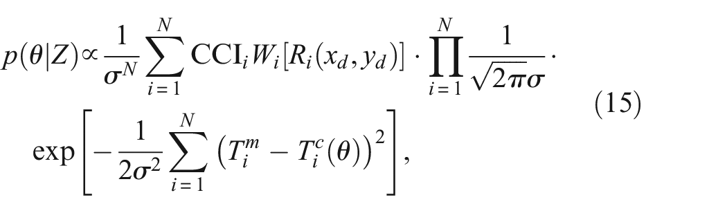
Therefore, substituting Equation (11) and Equation (14) into Equation (12), the posterior distribution of the unknown parameters is obtained as:
The posterior distributions used in Bayesian inference are often complex, which makes it difficult for Monte Carlo methods to extract independent samples. In such cases, the Markov chain Monte Carlo method (MCMC) is usually used to conquer this problem. The MCMC process produces a Markov chain whose stationary distribution is equal to the target distribution. The posterior of the unknown parameters can be obtained using the samples, and the corresponding predictions can be made. In this study, an MCMC algorithm was used to sample the posterior distributions of the unknown parameters, and the detailed description about the MCMC algorithm could be found in Nichols et al. 64 Next, the effectiveness of the proposed damage localization approach was investigated numerically and experimentally.
Numerical study
Finite element model
The finite element method (FEM) can be used to obtain damage-related information so that the accuracy of the proposed and traditional damage localization methods could be compared. Therefore, FEM studies were first conducted to verify the feasibility and demonstrate the effectiveness of the proposed damage localization method.
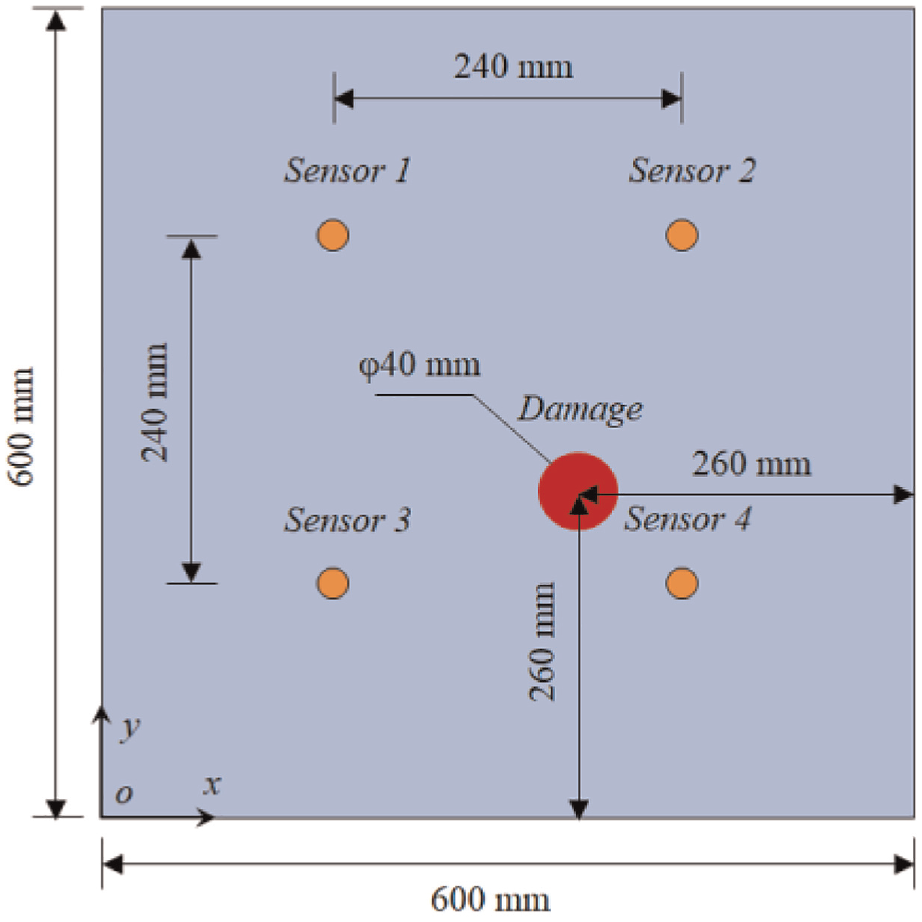
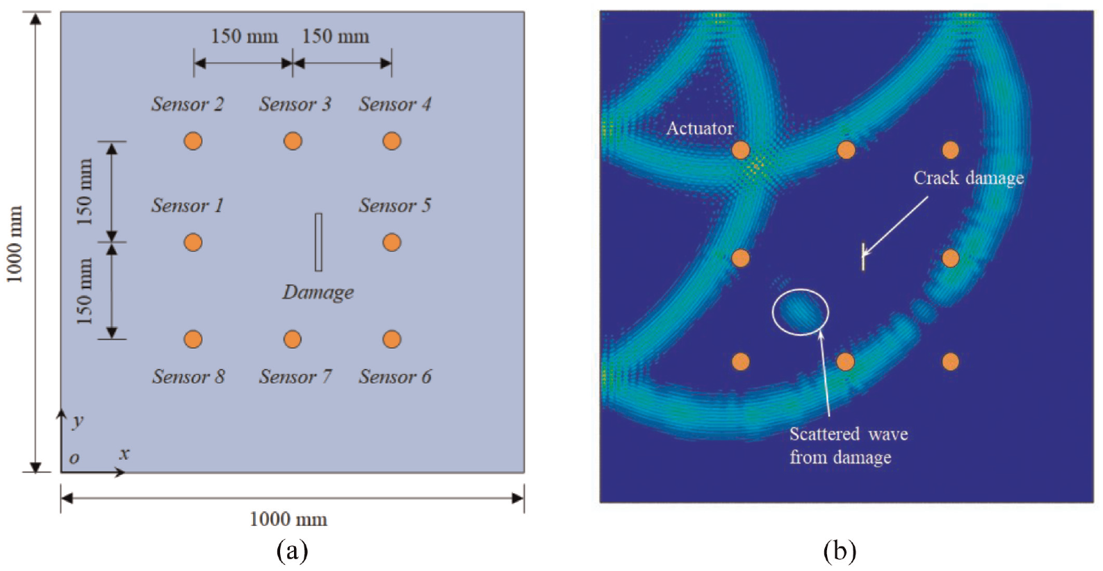
To generate synthetic scattered Lamb waves, a three-dimensional steel plate model was established in the commercial finite element software ABAQUS. The ABAQUS explicit dynamical analysis scheme was applied to obtain the ultrasonic responses under different conditions. As shown in Figure 6, three-dimensional sizes of the steel plate are
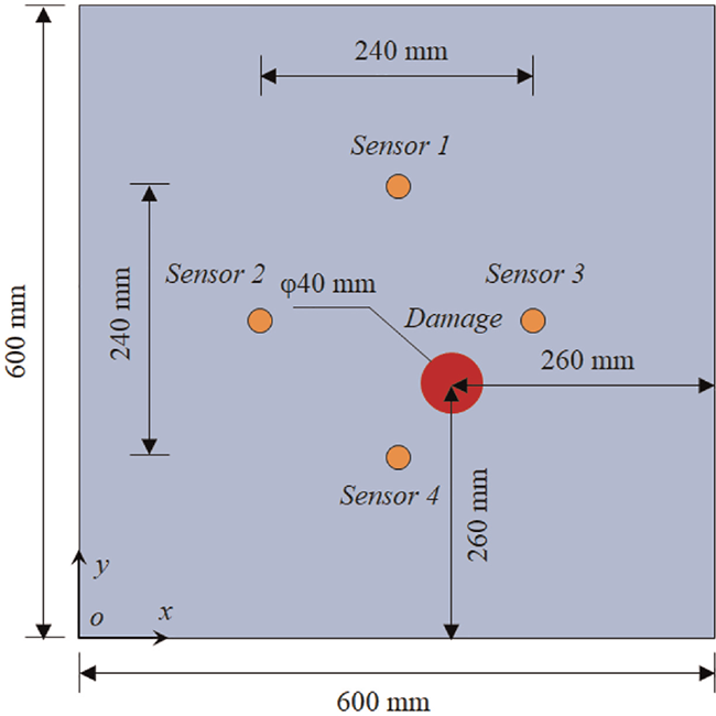
Schematic setup for numerical study including sensor array and steel plate with damage.
Due to dispersive characteristic of Lamb waves, the response signals received by transducers are usually notoriously complicated. In addition, fewer mode in the forward process is conducive to reducing the complexity of signal processing and calculating the time difference expediently. Based on dispersion curves, as shown in Figure 7, a narrow-band five-cycle 200 kHz sinusoidal signal modulated by a Hann window was used as the excitation signal. In the simulation analysis, a fine grid featuring at least 10 elements across the wavelength
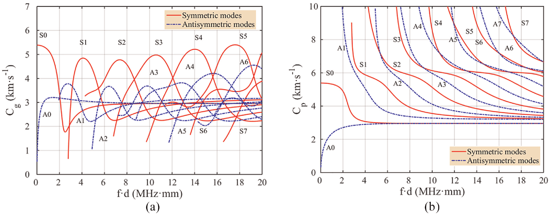
Dispersion curves of a steel plate: (a) group velocity and (b) phase velocity.
Numerical results
Figure 8(a) shows the snapshot of the Lamb wave propagation process in the steel plate specimen when the Sensor1 is loaded with excitation signal. It could be seen that the scattered wave generated by the damage diffused around, and could be received by other sensors in the plate. The excitation signal was applied in the four sensors in sequence, and the responses of other three sensors were extracted. In order to achieve baseline-free damage localization and improve the computing efficiency, the VTR technique was adopted in this research to obtain the reconstructed signal38,39,56,65,66 instead of generating and recording ultrasonic wave signals twice. It is also conducive to savings of hardware cost and the transfer function in the VTR process is estimated by using the forward response. As shown in Figure 8(b), the scattered waves in the sensing path 1–2, 1–3, and 2–4 (here, “1–2” means that Sensor1 is the actuator and Sensor2 the receiver, the rest are similarly defined) were obvious. And the ones in other paths, on the contrary, are barely to be distinguished. The possible reasons may be the relative positions of damage, wave source and wave receiver, the superposition of wave packets, and interferences of wave reflection from boundary. It distinctly leads to overlap of wave packets in the time-domain. Only the sensing paths that could perceive the damage information are desired for the damage localization. Otherwise, obstacles may appear for extracting damage features because of the interferences. It is also to be noted that both the direct wave and the damage-induced scattered wave in the selected paths (as shown, the time window in Figure 8(b)) were truncated, and then reemitted to the sensor in the virtual time-reversal process.
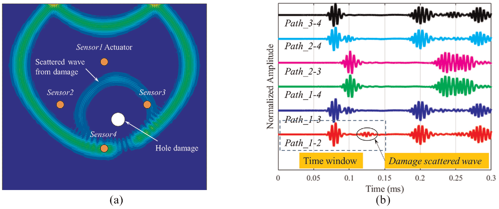
(a) The finite element propagation model with a hole damage and (b) the time-domain wave signals for all sensing paths.
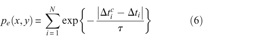
The envelopes of wave signals were obtained by the HT, as shown in Figure 9. The time differences
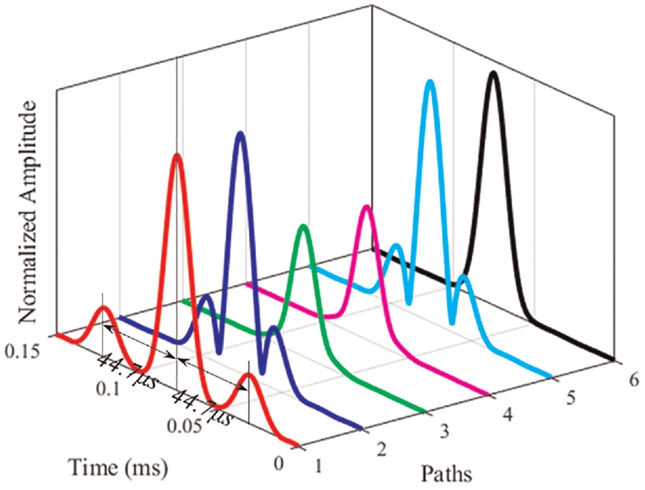
The time difference
Preliminary case
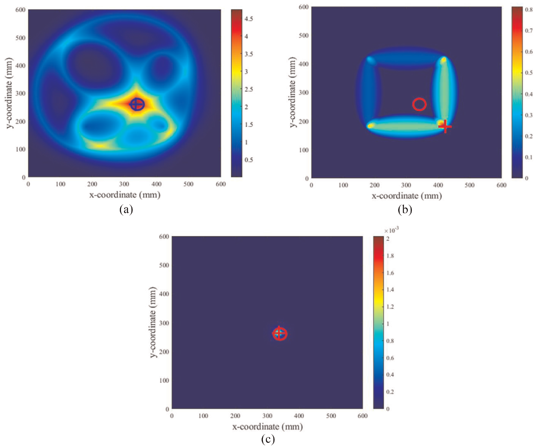
The propagation velocity of the A0 mode Lamb wave measured from the undamaged model was 2662 m/s at 200 kHz in the numerical study. The PDF of unknown parameters could be obtained from the Bayesian posterior distribution using the prepared
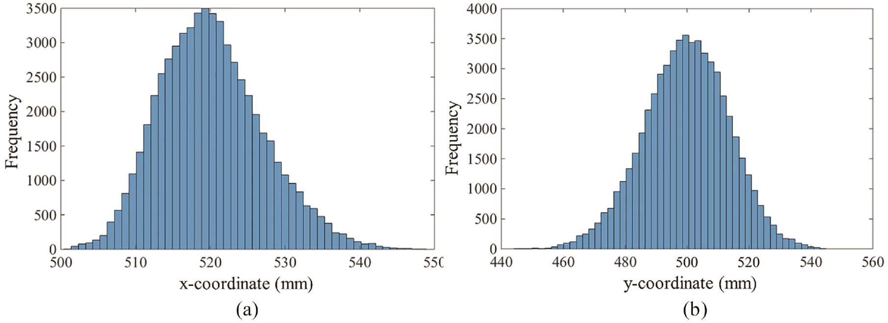
The histograms of the x
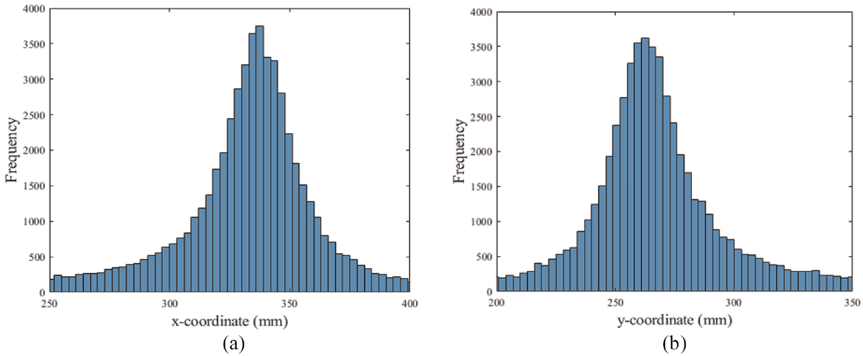
Histograms of MCMC samples for the parameters: (a) the x-coordinate (xd) and (b) the y-coordinate (yd).
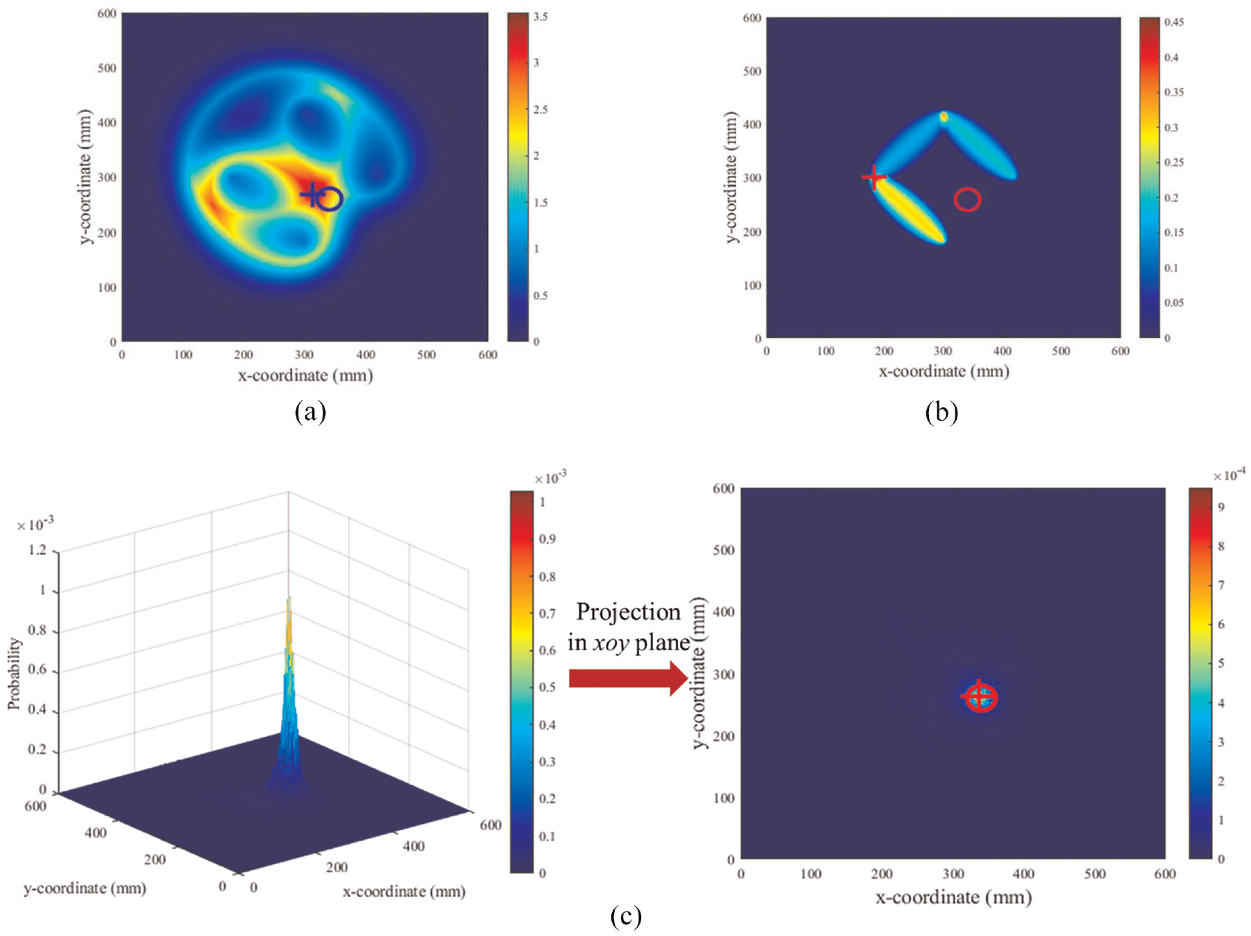
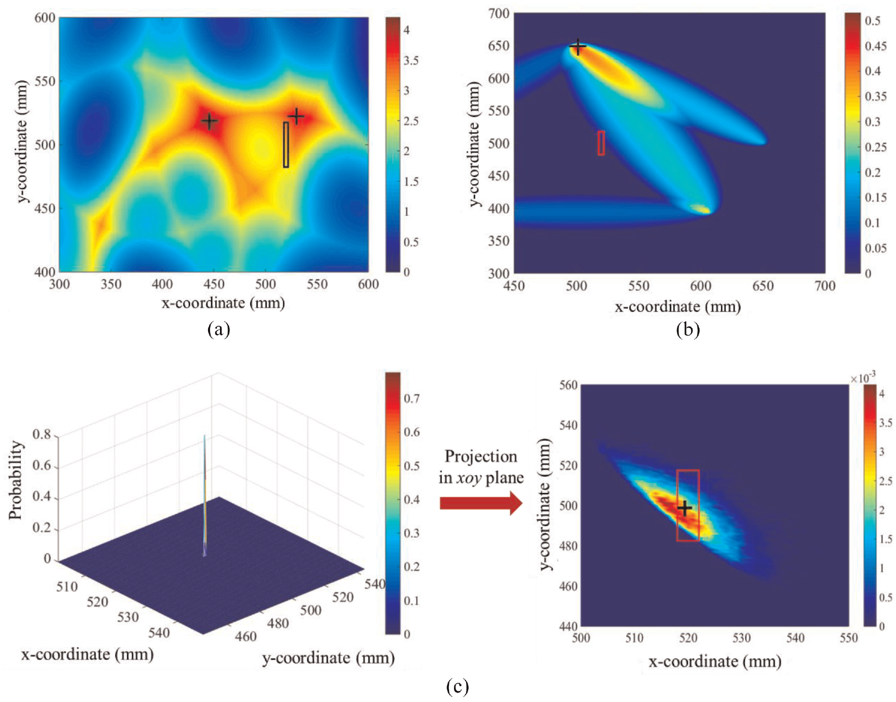
Damage localization results for preliminary study: (a) ETLM, (b) RAPID algorithm, and (c) probabilistic fusion method. (the mark “○” shows the actual damage position, and the mark “+” shows the result of the damage identification).
Parameter analysis
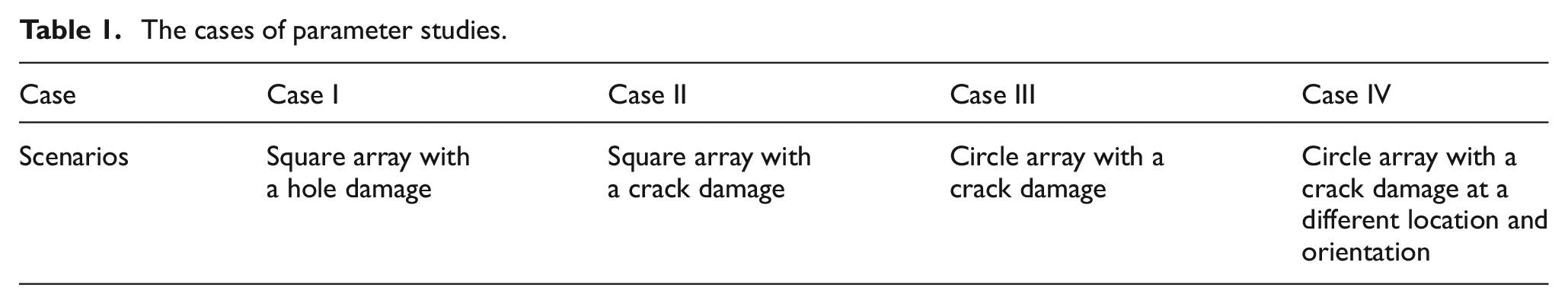
In order to explore the performance of the proposed approach under various configurations including different sensor arrangement, various damage types and locations, a series of parameter studies are carried out, as shown in Table 1.
The cases of parameter studies.
Case I: square array with a hole damage
In this scenario, the locations of transducers were altered, as shown in Figure 12. Four sensing paths, including
Schematic setup in the numerical studies for the case of square array with a hole damage.
Damage localization results for the case I: (a) ETLM, (b) RAPID algorithm, and (c) probabilistic fusion method.
Case II: square array with a crack damage
In order to further investigate the damage localization performances of the proposed method on different types of damages, a crack damage was explored in this case. The three-dimensional sizes of the steel plate are
Schematic setup in the numerical studies: (a) model dimensions and transducer configuration diagram and (b) the finite element propagation model with a crack damage.
As shown in Figure 14(b), the most significant difference between crack and hole damage is that the scattered wave induced by the crack mainly propagate along one specific direction, which brings much difficulties in damage localization. To investigate the interaction between ultrasonic waves with different propagation direction and the crack damage, the incident Lamb wave with different orientations (0°, 45°, and 90°) to crack were applied to the specimen, and the probing signal is introduced to the finite element model through out-of-plane forces, as shown in Figure 15. It can be seen that the amplitudes of the scattered wave in the directions of 180°, 135°, and 90° are maximum with the incident waves in the directions of 0°, 45°, and 90° with the crack. Therefore, a dense sensor network with eight PZT transducers was adopted to enhance the location accuracy and robustness for the crack with different orientations. Six sensing paths, including 1–2, 1–8, 8–2, 8–3, 3–2 and 3–7, were selected to localize the crack damage base on the scattered characteristic in time domain. Figure 16 shows the damage localizing results for the two traditional methods and proposed method, respectively. The localization result of the ETLM deviates little with the real crack while the damage location obtained from the RAPID algorithm significantly diverge from the real position. On the other hand, the identified possible damage location from the joint PDF meets well with the central coordinate of the crack, and the proposed method significantly reduces the damage artifact compared to traditional methods.
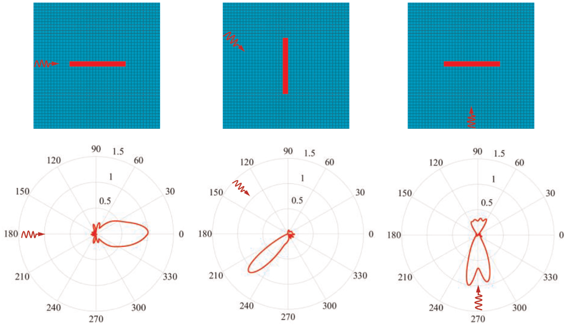
Three local finite element models for 0°, 45°, and 90° crack orientation with the incident Lamb wave.
Damage localization results for the case II: (a) ETLM, (b) RAPID algorithm, and (c) probabilistic fusion method (the rectangular mark shows the real damage position. The mark “+” shows the result of the prediction).
Case III: circle array with a crack damage
To investigate the influence of sensor arrangement on the damage localization, a circle array of transducer configuration was used to explore the effect on the damage localization, as shown in Figure 17(a). Eight sensors were attached on a circle area with a radius of 150 mm. Six sensing paths, including
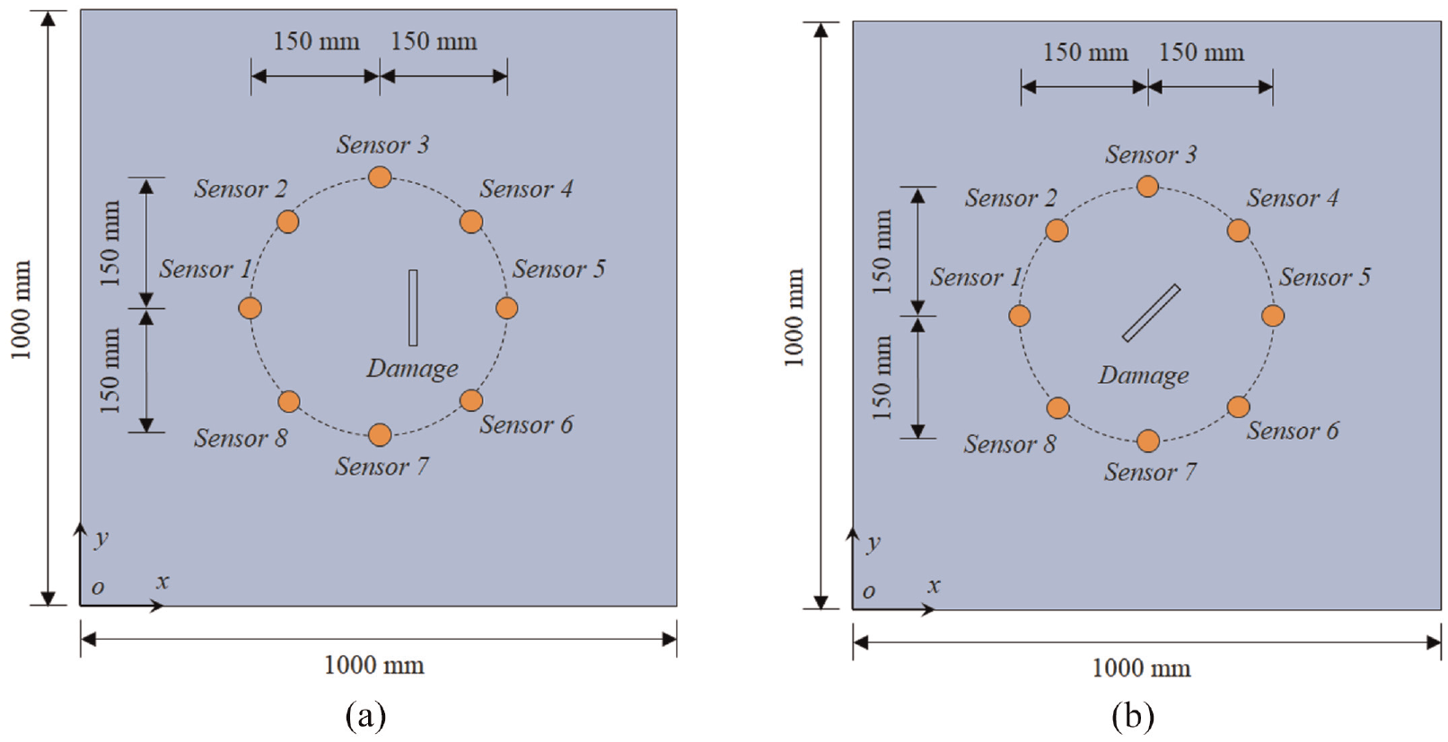
Schematic setup in the numerical studies: (a) the circle array with a crack damage and (b) the circle array with a crack damage at a different location.
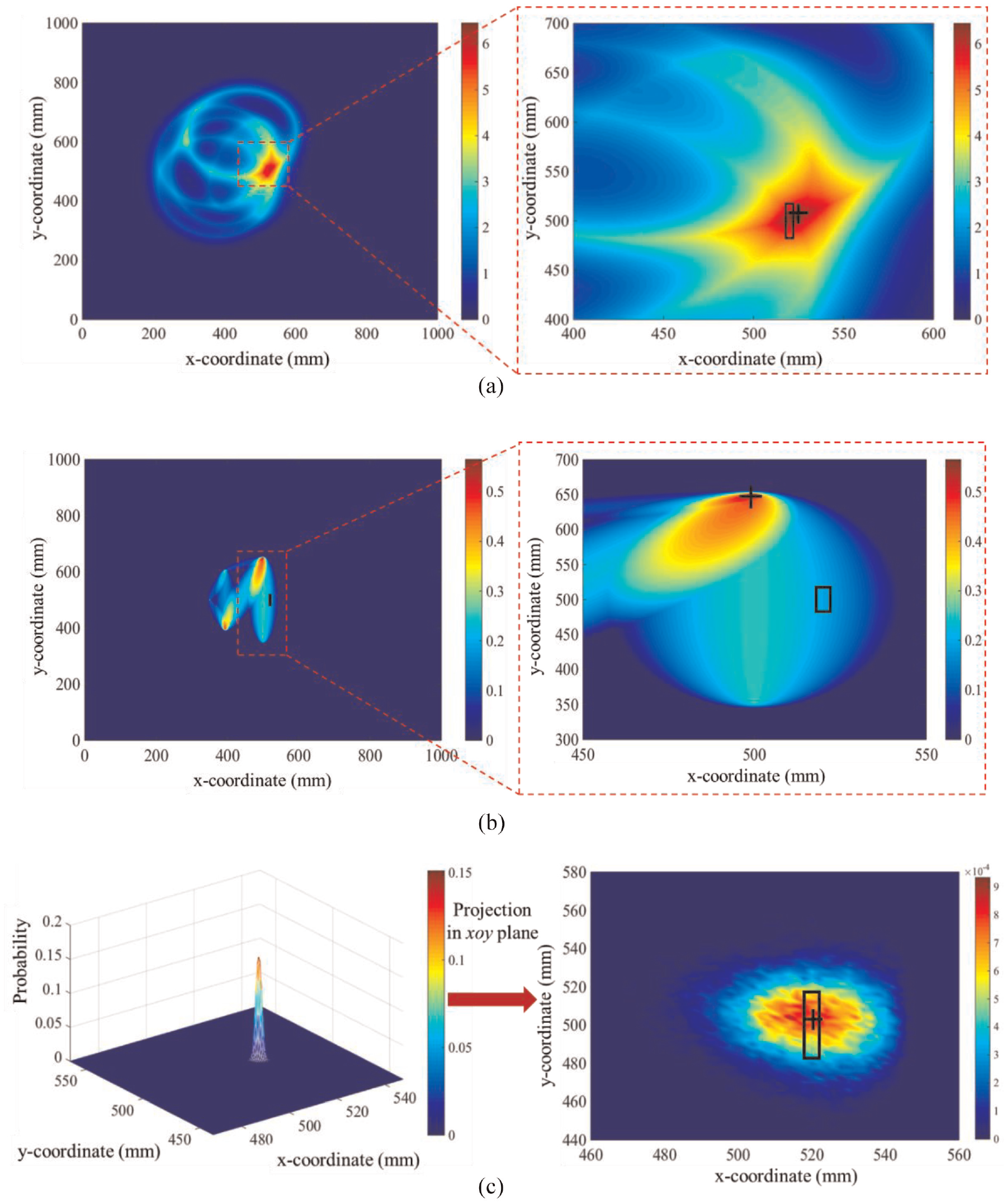
Damage localization results for the case III: (a) ETLM, (b) RAPID algorithm, and (c) probabilistic fusion method.
Case IV: circle array with a crack damage at a different location and orientation
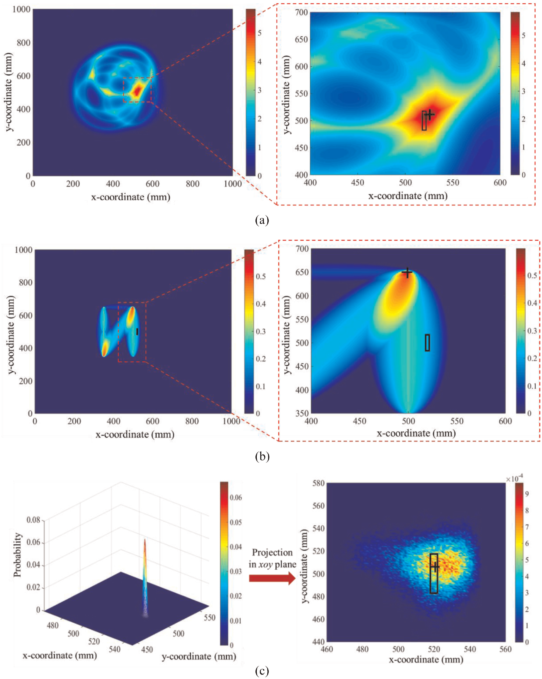
To investigate the performances of the three methods in damage location with different crack location and orientation, a slant crack with angle of 45° was introduced in the numerical model, as shown in Figure 17(b). Three-dimensional sizes of the crack are also
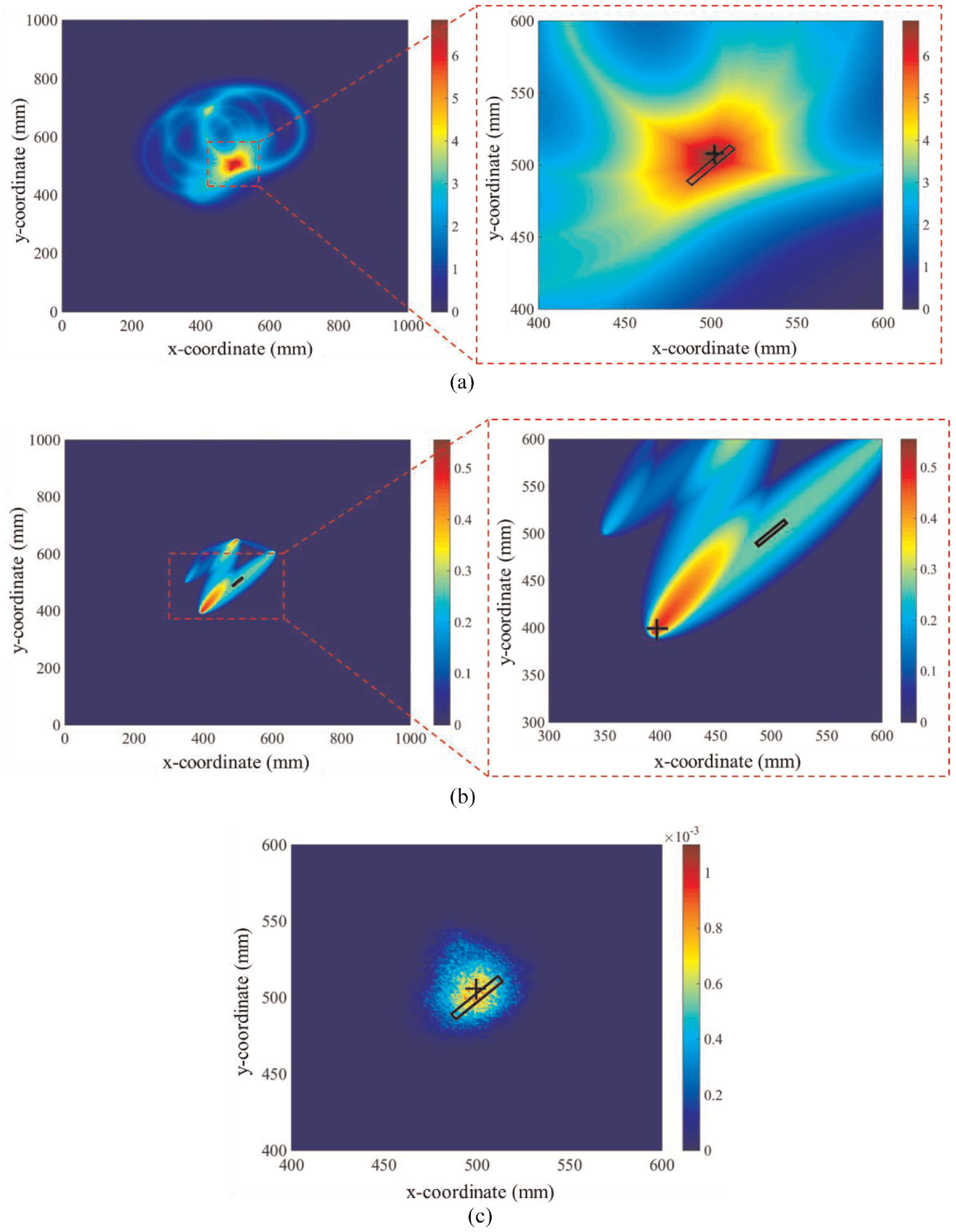
Damage localization results for the case IV: (a) ETLM, (b) RAPID algorithm, and (c) probabilistic fusion method (the slanted rectangular mark shows the real damage position, and the notation “+” shows the result of the prediction).
To further quantify the accuracy in term of the estimation error, the following error term
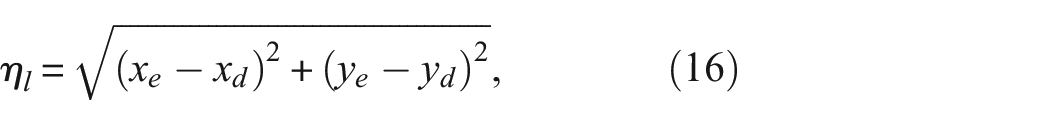
where
Summary of error analysis of all simulation studies.
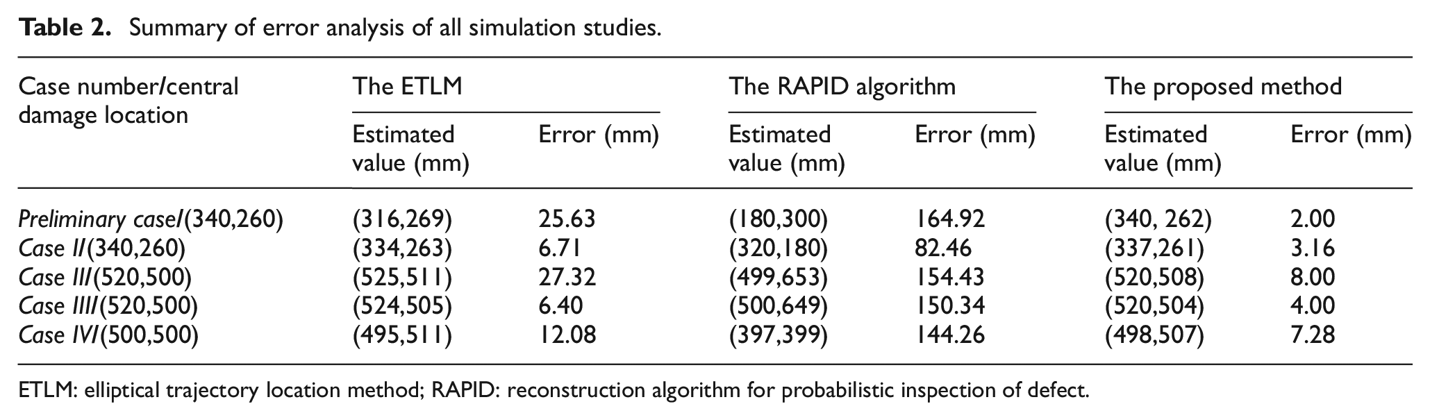
ETLM: elliptical trajectory location method; RAPID: reconstruction algorithm for probabilistic inspection of defect.
Experimental validation
Experimental setup
To further demonstrate the effectiveness of the proposed method on damage localization, experimental studies were conducted on a steel plate specimen with dimensions of
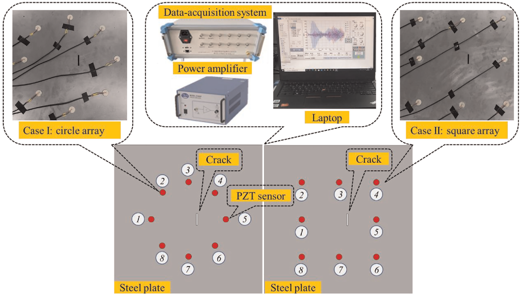
Experimental setup.
Experimental results
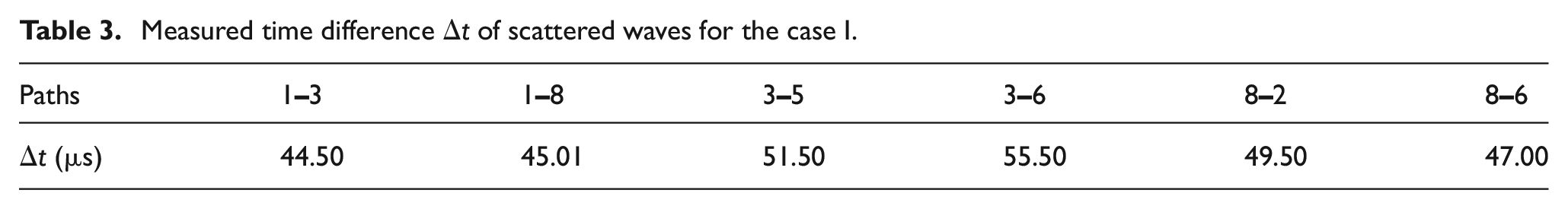
In this experimental research, two different sensor configurations were investigated to localize the crack damage, as shown in Figure 20. In case I, six sensing paths, including
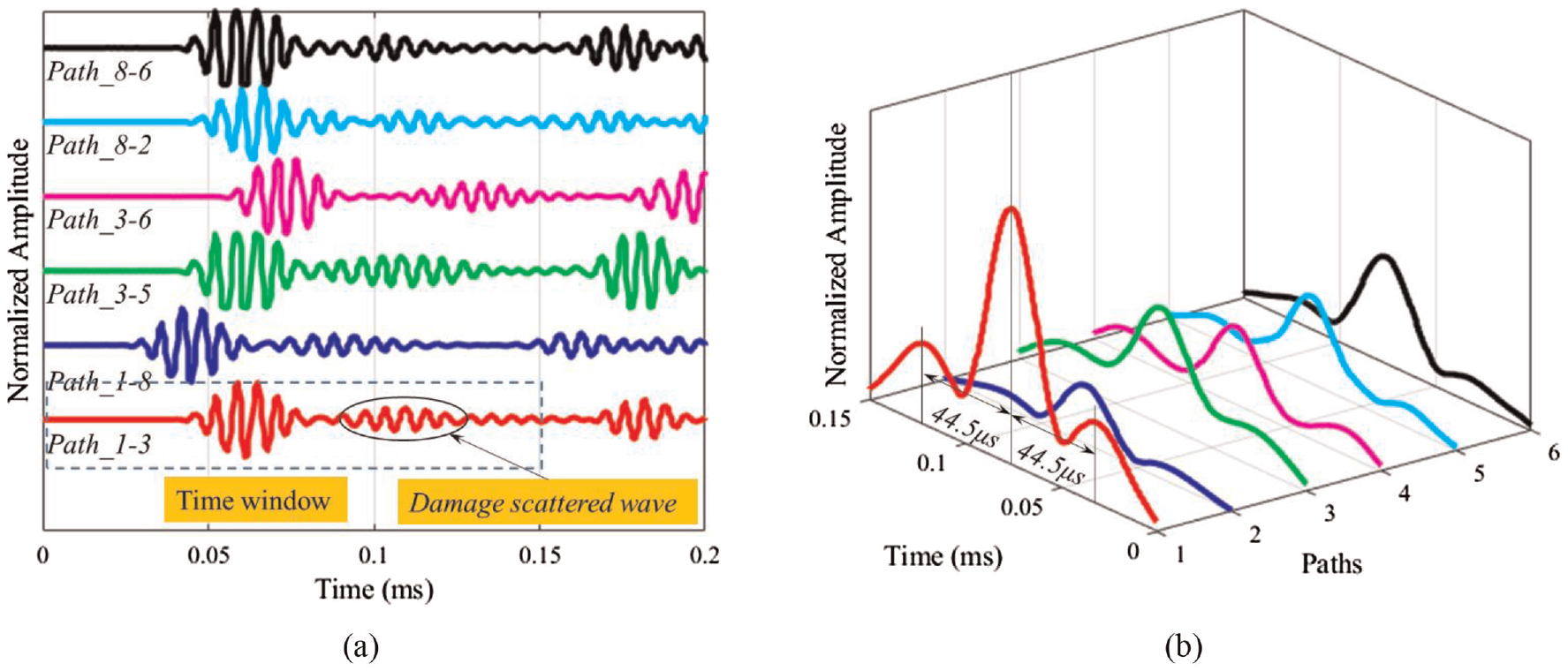
The signal processing for the case I: (a) time-domain wave signals for all sensing paths and (b) the time difference
Measured time difference
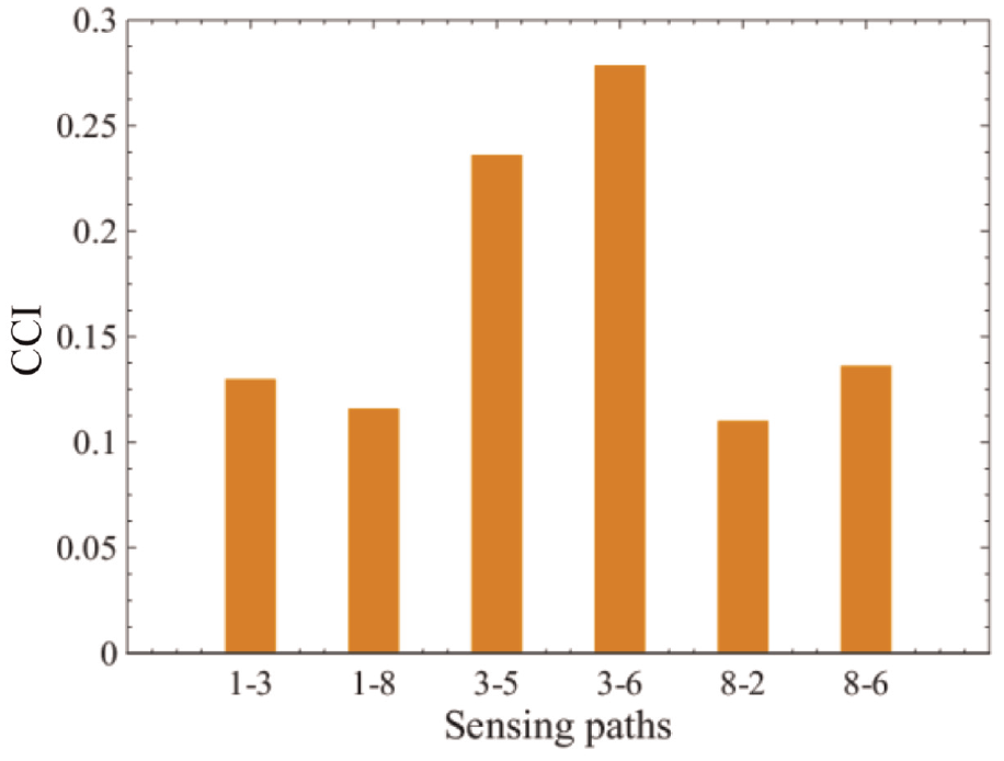
CCIs for the selected sensing paths for the case I.
Then, the MCMC procedure with the same parameter settings in numerical studies was performed using MATLAB built-in function mhsample. Figure 23 shows the histograms of the x
Histograms of MCMC samples for the parameters for the case I: (a) the x-coordinate (xd), (b) the y-coordinate (yd).
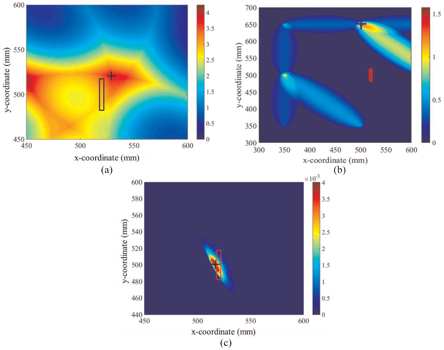
Damage localization results for the case I: (a) ETLM, (b) RAPID algorithm, and (c) probabilistic fusion method (the rectangular mark shows the real damage position, and the notation “+” shows the result of the prediction).
To further experimentally explore the effect of the sensor distribution manner on the damage localization accuracy, case II with square sensor configuration was investigated. Six sensing paths including
Damage localization results for the case of square array with a crack damage in the experiment: (a) ETLM, (b) RAPID algorithm, and (c) probabilistic fusion method.
To further evaluate the localizing accuracy, the error term defined by Equation (16) was used to compute the estimated errors. All the estimated results are calculated and compared to investigate the effectiveness of each method, as shown in Figure 26. Similar to the numerical findings, the proposed probabilistic fusion method could not only realize more accurate and reliable damage localization than the ELTM and RAPID, but also eliminate the artifacts compared to ELTM and RAPID by integrating damage features to fully exploit, as shown in Figures 24 and 25.
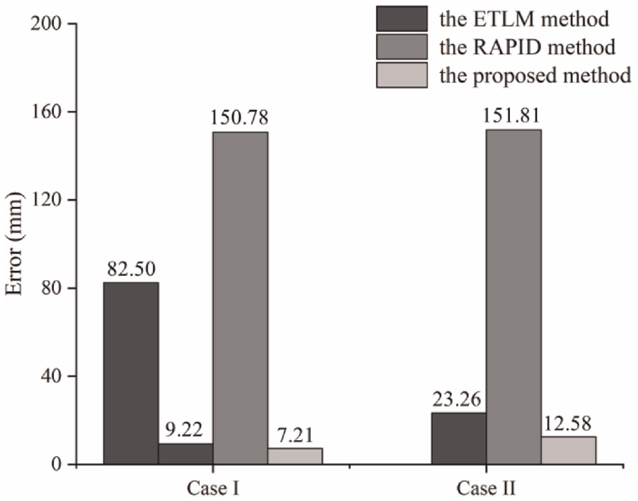
The estimated errors for the three methods in the experiment (case I: the circle array with a crack damage and case II: the square array with a crack damage).
Discussion
According to the numerical and experimental studies, including different configurations of damage cases and transducer distributions, the localization results of the RAPID algorithm largely deviate from the actual location, and the ETLM exhibits relatively better accuracy than RAPID but has more visible artifacts. On the contrary, the proposed probabilistic fusion method yields exclusive and accurate results compared to two existing methods, which demonstrated that the proposed probabilistic fusion method could efficiently integrate damage features to realize more accurate damage localization and eliminate the artifacts. In order to further investigate the damage localization performances of the proposed method on different sensor network coverage areas, three coverage areas were considered by using numerical simulations. Figure 27 presents the localization results of the proposed probabilistic fusion method. With the increase of sensor network coverage areas, the estimated errors of three cases were 2, 4.6, and 5.7 mm, respectively. It is reasonable that the localization errors of the proposed method increase to some extent. The proposed probabilistic fusion method shows reliable localizing results, again demonstrating the effectiveness of the proposed method.
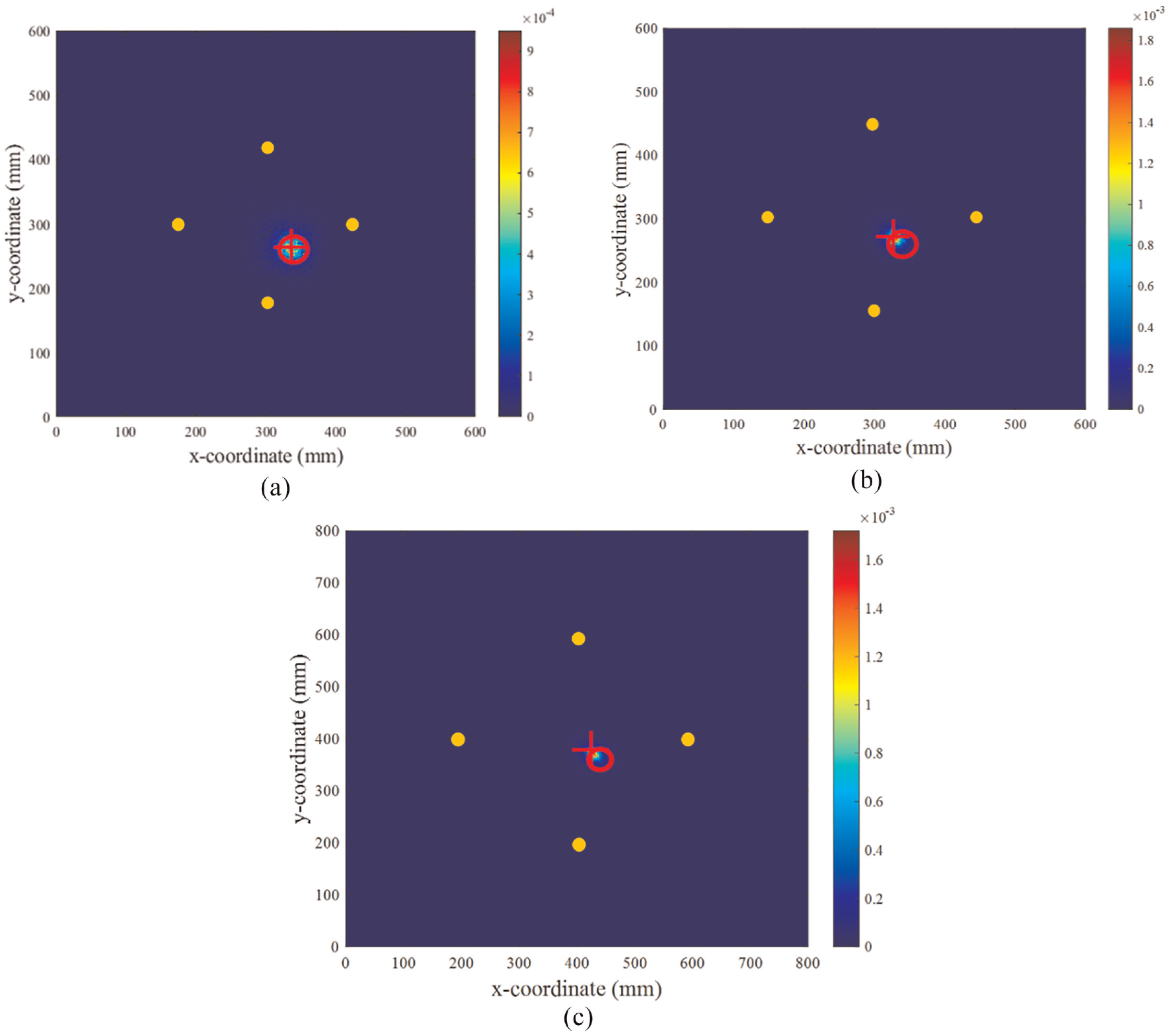
Compared studies with three different coverage areas: (a) 28,800 mm2, (b) 45,000 mm2, and (c) 80,000 mm2 (the mark “○”shows the actual damage position, the mark “+” shows the result of the damage identification and the yellow circle indicates the position of sensor).
Nevertheless, there are still some shortcomings that need to be further explored. Some influential factors (such as various damage sizes and pristine damage location, different probing frequencies) need to be considered and analyzed to investigate the performance of the proposed method in damage localization. In addition, intelligent algorithms (such as the deep learning) can be incorporated into distinguishing the wave packets induced by damage to improve the effectiveness of the proposed method on automated monitoring, and these will be considered in the authors’ future research.
Conclusions
In this paper, the Lamb wave-based time reversal method was first utilized to achieve baseline-free manner for obtaining damage features
Specifically, the proposed probabilistic fusion method could not only realize more accurate damage localization than the ELTM and RAPID algorithm, but also eliminate imaging artifacts. The efficient practical transducer configuration is determined by investigating the interaction between the Lamb wave and damage. The effect of different configurations of damage and transducers on the proposed probabilistic fusion method is less essential than that on the ELTM and RAPID algorithm, and it needs more transducer configurations and sensing paths for the ELTM and RAPID algorithm to achieve accurate damage localization. In addition, with the increase of sensor network coverage areas, the localization errors of the proposed method increase slightly, but it is still relatively small and acceptable. It should be noted that there are some interferences for the time-reversal method to extract damage index because of the superposition of wave packets and the influence of the boundary reflected waves. In the future, a more efficient and effective method for determining the sensing paths and extracting damage index for damage localization needs to be explored under a variety of operational and environmental conditions, and the feasibility of the proposed damage localization method based on Bayes approach on structures with complex geometries (rail, H-beam and steel truss, etc.) will be explored.
Footnotes
Declaration of conflicting interests
The author(s) declared no potential conflicts of interest with respect to the research, authorship, and/or publication of this article.
Funding
The author(s) disclosed receipt of the following financial support for the research, authorship, and/or publication of this article: This research is supported by the National Natural Science Foundation of China (Grant number 52020105005). The authors greatly appreciate financial supports.