
Abstract
This paper presents a damage sparse imaging method using multipath-scattered Lamb waves. It leverages a large number of echoes and reverberations in the recorded signal that may be usually ignored in conventional methods. First, reflections of Lamb waves at free edges are viewed as waves transmitted from a virtual transducer which is located at the mirror point of the actual one. On this basis, an optimized transducers-layout strategy is proposed based on the multipath propagation model of the Lamb wave. Benefiting from that, the direct damage-scattered wave and several waves scattered by both the damage and edges could be separately identified in the time domain, and further, each wave could be matched with a sensing path (either actual or virtual) in the expanded sensor network. Subsequently, a dictionary is constructed from the Lamb wave propagation and scattering model. By solving the sparse reconstruction problem, the pixel value of each point in the region of interest is obtained, and the whole area can be finally visualized. The proposed method is validated using experiments conducted on an aluminum plate with simulated damages. Results show that the damages can be correctly detected and accurately localized with only a single transmitter–receiver pair.
Keywords
Introduction
Due to the capacity to travel large distances without significant attenuation and high sensitivity to various types of damage, Lamb waves are utilized extensively for structural health monitoring (SHM) of thin-walled structures, such as plates, pipes, and shells.1–3 In a typical SHM system, Lamb waves are generally transmitted and received by a specific array of transducers to capture enough information for damage identification, localization, and quantification.4,5 Specifically, a number of transducers are usually required to be mounted on or embedded in the structures. In this case, it is of great significance to use as few transducers as possible, to reduce the cost, weight, and complexity of the SHM system.
The spatially distributed transducer array has become an intensive topic in the field of SHM in recent years. A variety of damage imaging techniques, such as the delay-and-sum (DAS) beamforming,6,7 the minimum variance distortionless response imaging,5,8 and the reconstruction algorithm for probabilistic inspection of defects method,9,10 are commonly used with a sparse array. For instance, Thiene et al. 11 presented an optimal sensor placement algorithm for attaining the maximum area coverage within a sensor network by considering the properties of Lamb wave propagation and the geometrical complexity of the structure. Tang et al. 12 employed the support vector machine classification models and Fisher clustering algorithms and achieved the damage classification and identification with a sparse sensor array. Yang et al. 13 proposed an ameliorated multiple signal classification (Am-MUSIC) technology for damage imaging using a sparse sensor network, which successfully addressed the blind spots problem caused by the MUSIC algorithm with dense linear arrays. Levine and Michaels 14 presented a sparse reconstruction imaging method by sparsely decomposing the scattered signals in a preconstructed dictionary, which outperforms the traditional DAS imaging method. Xu et al. 15 proposed a Lamb wave imaging method based on a weighted sparse reconstruction using a sparse array of transducers. By using the appropriate weights, better imaging performance can be achieved, for example, with fewer artifacts. These researchers have made great efforts in exploiting information from sparse arrays. However, only the first arrival wave packets in the recorded Lamb wave signal are used, while a large amount of valid information encoded in echoes and reverberations is discarded.
Considering the discarded waves containing the multipath scattering of damage and geometric features, the transducer quantity may be further reduced if the information encoded is exploited.16,17 Zhang et al. 18 leveraged the multipath reflections in DAS beamforming to reveal shadowed parts of the defects and enable defect perimeter detection. However, scattered wave packets from different paths may overlap, leading to the poor interpretability of the multipath-scattered signal. Ebrahimkhanlou et al. 19 proposed a model-based Lamb waves imaging algorithm where multiple echoes caused by reflections from the edges are leveraged to enhance imaging performance. However, the envelope estimation is repeated for each pixel, it requires several calls to the model and takes longer to be computed. Hall and Michaels 20 established a multipath Lamb wave imaging algorithm using late-arrival echoes and reverberations, which can detect and locate damage with only a small number of transducers. However, the baseline is obtained from wavefield data collected with a scanning laser vibrometer, resulting in a higher cost for the SHM system. Huang et al. 21 presented a multipath baseline-free damage imaging method that leverages the extra reflections recorded in the Lamb wave signals for structural prognosis, but the assumption that there is no overlap between the scattered wave packets from different paths in the detection region may be challenged.
Aimed at the high cost of SHM systems and the poor interpretation of the multipath-scattered signal, in this paper, a damage sparse imaging method using multipath-scattered Lamb waves is proposed, which realizes damage location with only a single transmitter–receiver pair. First, based on the multipath propagation model of Lamb wave, an optimized transducers-layout strategy is proposed to improve the interpretability of the multipath-scattered signal and ensure a large difference between the distances of any two sensing paths in the expanded sensor network. On this basis, the damage-scattered wave packets of several paths are separated and extracted from the residual signal for damage localization imaging. Finally, a sparse reconstruction imaging method is established to accommodate the multipath-scattered waves. The proposed multipath imaging method would reduce the cost, weight, and complexity of the SHM system compared to the direct-path sparse reconstruction imaging method.14,15 The rest of this paper is organized as follows. In the section “Lamb wave multipath scattering,” the theoretical analysis of Lamb wave multipath scattering is given. In the section “Methodology,” the methodology for optimization of sensor positions and the sparse reconstruction imaging method are introduced. In the section “Experimental study,” an experiment is conducted to validate the effectiveness of the proposed method. A performance analysis is made about the proposed method in the section “Performance analysis.” The final section draws the conclusions.
Lamb wave multipath scattering
In this section, the background of Lamb wave propagation is reviewed. Theoretically, Lamb wave is multimodal at any frequency when it propagates in thin-walled structures. In addition, Lamb wave has the dispersion characteristic, which causes the wave packet to spread out in the time domain when propagating in the medium. For an excitation with source time function s(t), a single Lamb wave mode measured after traveling distance L in an infinite thin plate can be expressed as 22
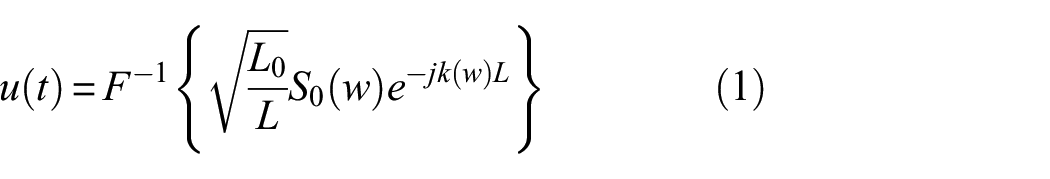
Here F{} is the Fourier transform and F−1{} is its inverse. u(t) is the measured signal in the time domain. L0 is a reference distance and L is the distance from the transmitter to the receiver. t is the time and w is the angular frequency. S0(w) is the excitation signal in the frequency domain, k(w) is the wavenumber of a specific Lamb wave mode, and j is the imaginary unit.
Suppose a scatterer is located between the transmitter and the receiver. Assume that there is no mode conversion in the damage reflection process. Then the scattered signal y(t) in the time domain can be expressed as
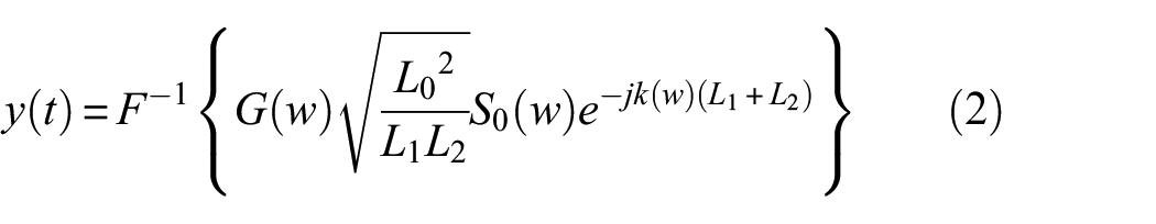
where the frequency-dependent parameter G(w) is the corresponding scattering coefficient, L1 is the distance from the transmitter to the scatterer, and L2 is the distance from the scatterer to the receiver.
In addition, other singular features in the structure, such as stiffeners and edges, may cause additional reflections, producing many more waves that propagate in the structure and scatter at the damage. For illustration, Figure 1 gives the possible scattering paths as the transmitter
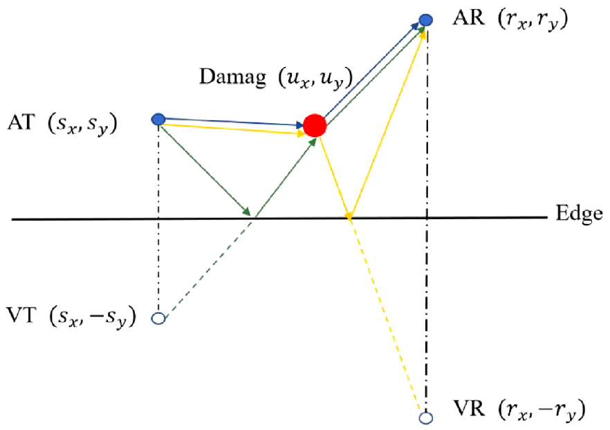
The possible scattering paths contain not only the direct scattering path but also the edge reflection paths related to the damage.
The multipath scattering between the reflectors and damage is considered. Assuming that acoustic rays propagate according to Fermat’s principle. The edge can be considered as a mirror, which can add virtual transducers into the sensor array. The position of the virtual transmitter or receiver is determined by the position of the actual transmitter or receiver and the mirror, while it is independent of the damaged position. The virtual transmitter and receiver are located at the symmetrical position of the actual ones with respect to the edge. Therefore, the multiple scattering path can be simplified to a direct scattering path from the virtual/actual transmitter to the damage and back to the actual/virtual receiver. Assuming that there is no mode conversion at the free edges23,24 and ignoring scattering waves that interact multiple times with the damage, the damage multipath-scattered Lamb waves can be expressed as
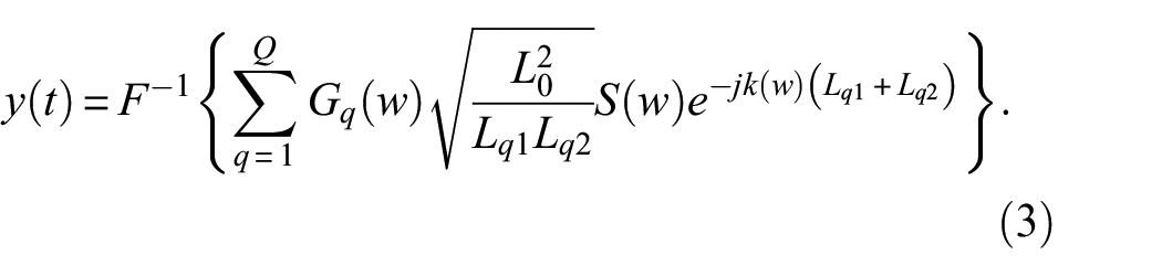
Here Q is the total damage scattering path, Gq(w) is the scattering coefficient corresponding to the qth scattering path. Lq1 is the distance from the transmitter to the damage corresponding to the qth path and Lq2 is the distance from the damage to the receiver corresponding to the qth path.
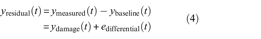
The signals collected by the transducers consist of direct signals, scattered signals, and stochastic noise. In SHM, the baseline signal ybaseline(t) is usually acquired when the structure is in a known state (usually healthy). The residual signal yresidual(t) is obtained by subtracting the corresponding baseline signal from the measured signal ymeasured(t), which can isolate the effects of unknown damage introduced in between the two measurements. The stochastic noise edifferential(t) comes from both measurements. Their relationships are shown in Equation (4):
Methodology
Optimization of transducers’ position
The wave packets received by the transducer from multiple paths tend to overlap, which are hard to interpret and are intentionally ignored. Through optimizing the position of the transducers, it is possible that the scattered wave packets from different paths appear in a specific sequence. Moreover, the difference in travel time of two adjacent wave packets in the residual signal may be greater than half of the duration of the excitation signal. Benefiting from that, several wave packets in the residual signals corresponding to the scattering paths could be clearly identified. The interpretability of the multipath-scattered signals can be improved. More individual damage information can be extracted and separated from the collected signals. Suppose we want to extract the damaged scattered wave packets of the first P paths in the received damage signal. The transducers’ position can be optimally determined by the following steps:
Step 1: Divide the region of interest into a number of grids, and fix the position of a transducer.
Step 2: Arbitrarily select the position of another transducer. Identify the possible Lamb wave propagation paths. Calculate the location of the virtual transmitter and receiver by considering the edge of the structure as a mirror.
Step 3: The multiple scattering paths can be simplified to a direct scattering path from the virtual/actual transmitter to the scatterer and back to the actual/virtual receiver. Calculate the distance of each travel path by connecting the transmitter, the corresponding scatterer at any grid, and the receiver in turn.
Step 4: Determine if the following conditions are reached for the chosen transducer position:
(1) Always ensure at each point in the region of interest that the distance of the first path L1 is less than the distance of the second path L2, and further, the distance of the pth path is less than that of the (p + 1)th one, that is, Lp < Lp+1, for p = 1, 2,…, P−1. Here, P is the number of reflected wave paths planned to be utilized. (2) Always ensure that the difference in distance between any two travel paths (e.g., Lii and Ljj) is larger than half the distance of the excitation signal in distance domain Lext, that is, min (Ljj−Lii) ≥ 1/2Lext.
Step 5: If the position of the chosen transducer meets the conditions of Step 4, the transducer position is determined. Otherwise, repeat Steps 2–4 until a suitable transducer position is found.
Multipath Lamb wave imaging by sparse reconstruction
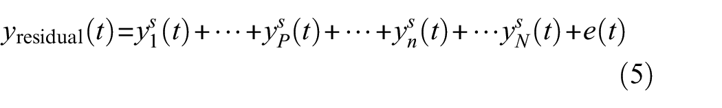
Although only one transmitter–receiver pair is used for signal acquisition and the residual signal can be obtained by subtracting the corresponding baseline signal from the measured signal Equation (4), the residual signal contains a series of wave packets resulting from multiple scattering related to the damage. Based on the structure of the specimen and the regions of interest, the transducer optimization is conducted to determine the positions of transducers (see section “Optimization of transducers position”). Benefiting from the optimized transducer’s layout, several damage scattered wave packets in the residual signal could be matched with the corresponding sensing path (either actual or virtual) in the expanded sensor network. Furthermore, these damage-scattered wave packets could be clearly identified and separated in the time domain. Then the multipath Lamb wave imaging by sparse reconstruction is established. Assuming there are a total of N wave packets in the residual signal and the first P ones of them can be identified and separated. Then the residual damage signal can be expressed as
where
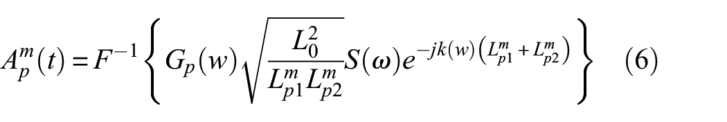
The region of interest in the inspected plate is discretized into M grids. Each grid is considered a potential scatterer. The corresponding scattered signal can be modeled using Equation (2). Hence, there would be a total of P × M scattered signals modeled for a transmitter–receiver pair with the whole P paths and M grids. For example, the scattered signals for the mth grid and the pth path can be expressed as
Then it is possible to form a dictionary
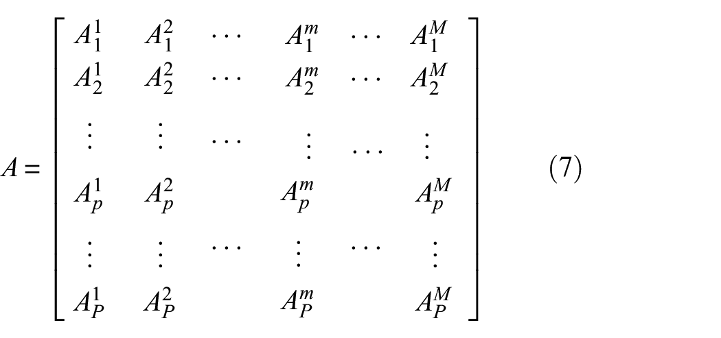
Without considering the interaction between the scatterers, the total scattering field due to multiple scatterers is equivalent to the sum of the effects of each scatterer considered individually. Then the scattered signal of each path
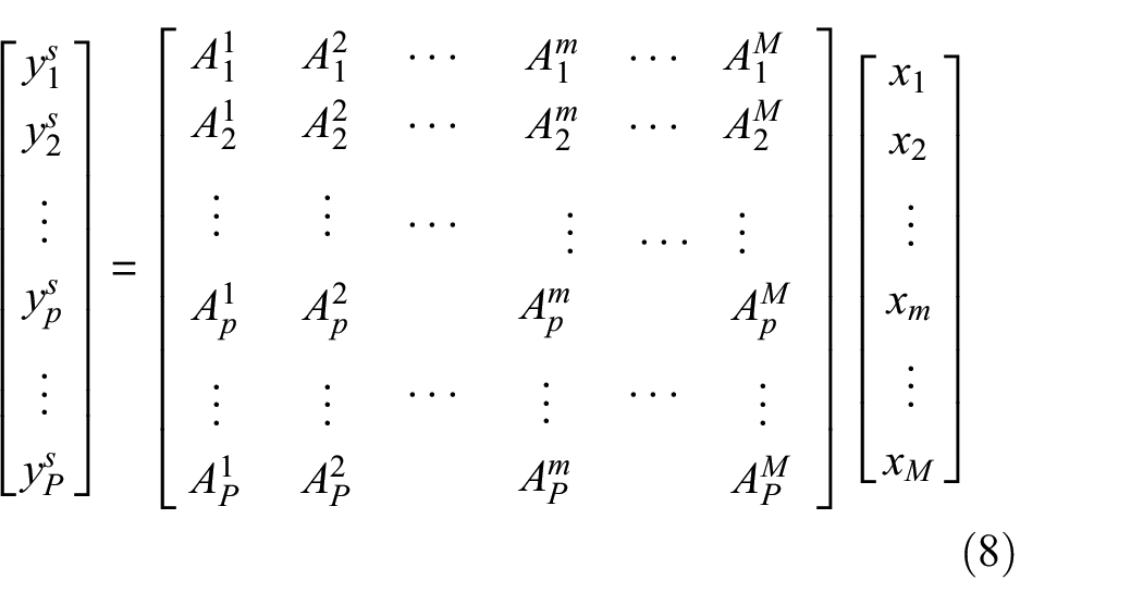
The above equation can be formulated as

where
In most cases, the majority of the inspected plate is undamaged. In other words, the number of damages Mdamage in the plate is much fewer than the number of discretized meshes M (i.e., Mdamage << M). The vector x is sparse and can be recovered by solving the sparse reconstruction problem. 25 The most common approaches to solve this problem are one-norm optimization methods, 26 iterative greedy algorithms, 27 and the sparse Bayesian learning (SBL) strategy. 28 Here we consider the basis of pursuit denoising. 29 It solves an optimization problem that can be expressed as

where σ is the standard deviation of the noise term e.
Since the predicted scattered signal in dictionary A contains both amplitude and phase information, in most cases the scattering pattern of the damage is unknown and its phase characteristics are difficult to predict correctly, which will possibly lead to the phase mismatch between the measured signal y and the atoms in dictionary A. Ultimately, it will probably result in poor imaging performance. The original signals in y and A are replaced with the corresponding envelopes to improve the imaging performance.14,15

where H{} denotes the column-wise discrete Hilbert transform. Once the recovered vector x has been obtained. The pixel value at each pixel position is expressed as |x|, which will bring into sharper focus the location with the highest probability of damage. The key steps of the proposed method are listed in Figure 2.
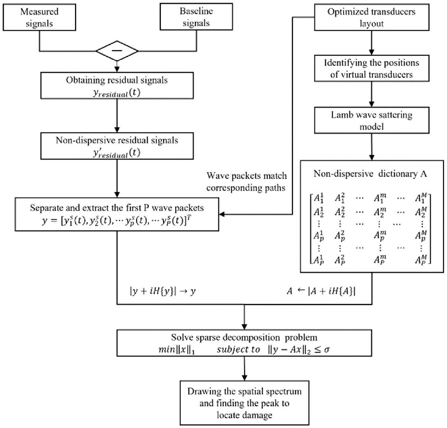
The key steps of the proposed method.
Experimental study
Experimental setup
In this section, the experiment is conducted. The specimen is a 2024 T3 aluminum plate with dimensions of 1250 mm × 1250 mm × 2 mm. The primary imaging area of the experiments is a 520 mm × 520 mm square, as shown in Figure 2. The excitation signal takes a three-cycle toneburst signal centered at 60 kHz, for which the A0 mode is dominant for the plate thickness. It is first generated by an Agilent 33220A waveform generator and then amplified by an NF HSA4012 voltage amplifier. The peak voltage of the excitation signal injected in the transmitter is 75 V. Data acquisition is performed by a Tektronix DPO 5054B digital phosphor oscilloscope. The acquisition rate is 5 MHz and the data length is 10,000 points. A coordinate system is employed, whose origin of the coordinate is set at the lower left corner of the specimen. Two piezoelectric transducers (PZTs) (circular, P-51, with dimensions of Φ8 mm × 0.5 mm) are surface-mounted on the specimen with the coordinates of (500,160) mm and (750,70) mm (see Figure 3). Furthermore, as the additional mass can simulate the damage, the square magnets with a side length of 10 mm are selected and bonded on the plate surface of the aluminum plate. The experimental equipment is shown in Figure 4.
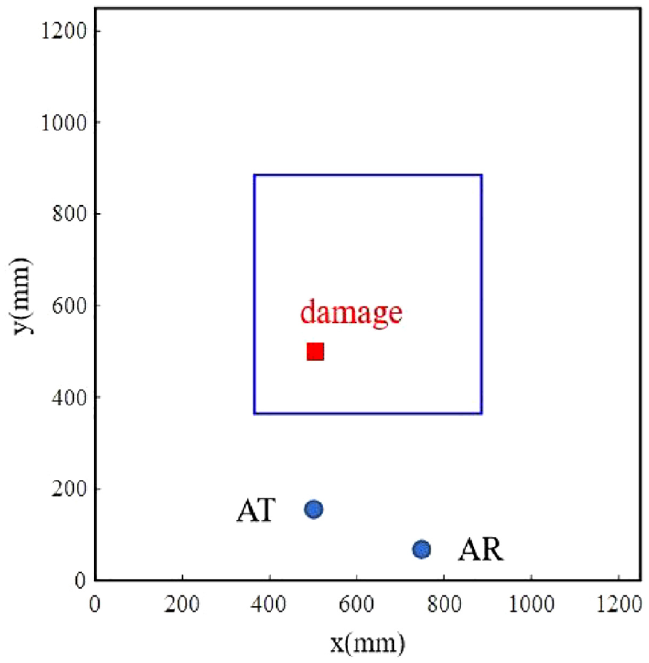
Schematic experiment diagram of the aluminum plate showing the two transducers and additional masses.
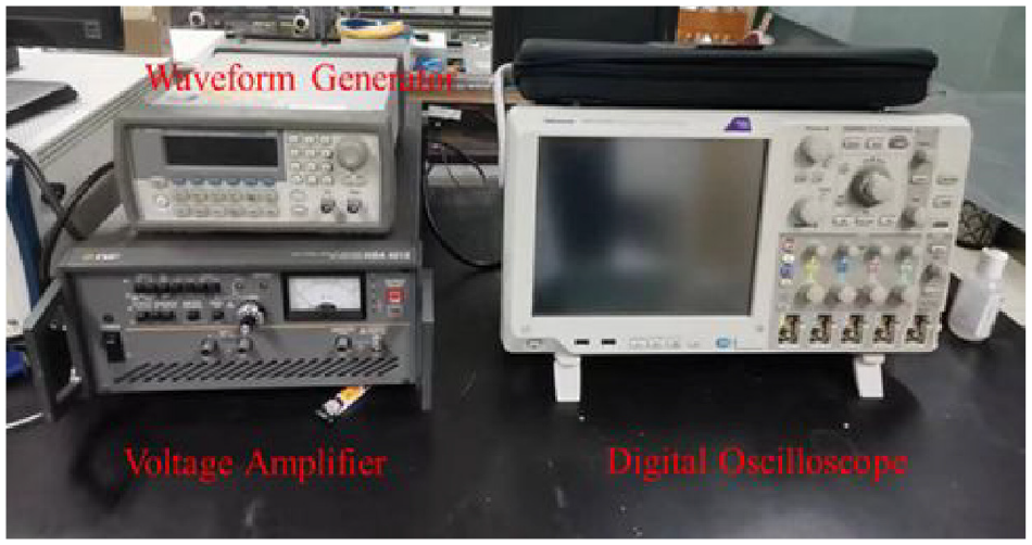
Photograph of the experimental equipment.
Both the actual transmitter (AT) and the actual receiver (AR) are arranged close to the bottom edge. As discussed in the section “Lamb wave multipath scattering,” the use of multipath scattering is equivalent to adding virtual transmitters and receivers. Figure 5 shows the first five paths for Lamb waves traveling from the transmitter to the receiver after being reflected by damage and the plate edge. In this paper, the scattered signals of the first three paths are mainly considered. Path 1 is the direct travel path. In path 2, the wave travels from the damage to the bottom edge and back to the receiver. In path 3, the wave travels from the bottom edge to the damage and back to the receiver. In path 4, the wave travels from the left edge to the damage and back to the receiver. In path 5, the wave travels from the damage to the right edge and back to the receiver.
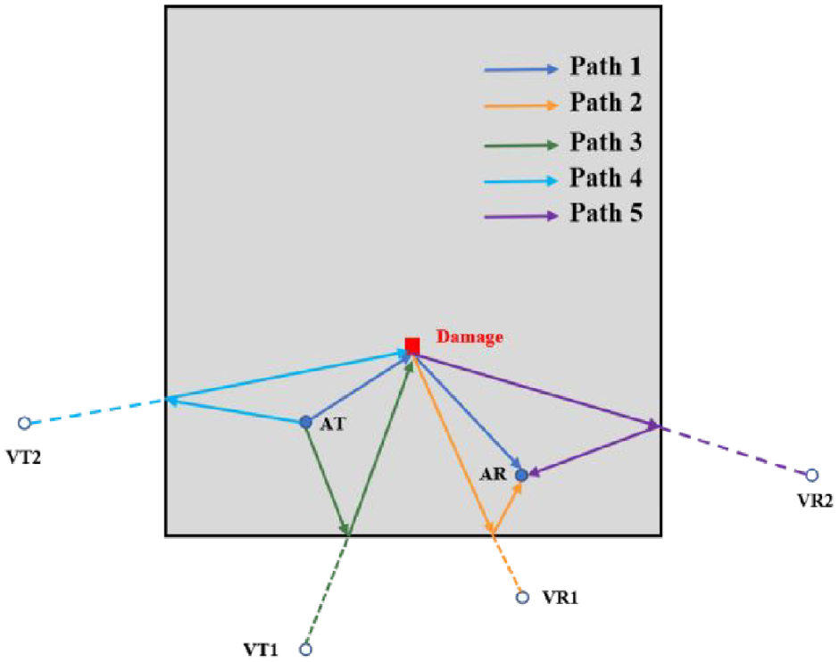
The diagram of the first five paths: path 1 is directly reflected wave path, paths 2–5 are scattering wave paths from the damage and edges to the receiver.
For each individual scatterer in the region of interest, the propagation distance of the corresponding path can be calculated by the coordinates of the transmitter, receiver, and scatterer. The distance distribution of the first five paths of any single scatterer in the region of interest is shown in Figure 6. The diagram in the blue dashed box of Figure 6 is a view of Figure 6 from a certain angle. It shows that the transducer positions meet the requirements of condition 1 of step 4 in the optimization of transducer positions methodology (i.e., for any individual scatterer in the region of interest, L1 < L2 < L3 < L4).
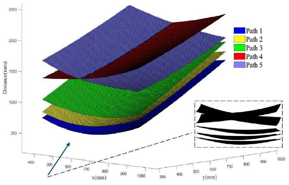
The wave packet propagation distance of the first five paths of any scatterer in the region of interest.
For any individual scatterer in the region of interest, between two Lamb wave travel paths, the difference of propagation distances is shown in Figure 7. The minimum distance difference and the position in which the scatterer is located are shown in Table 1.
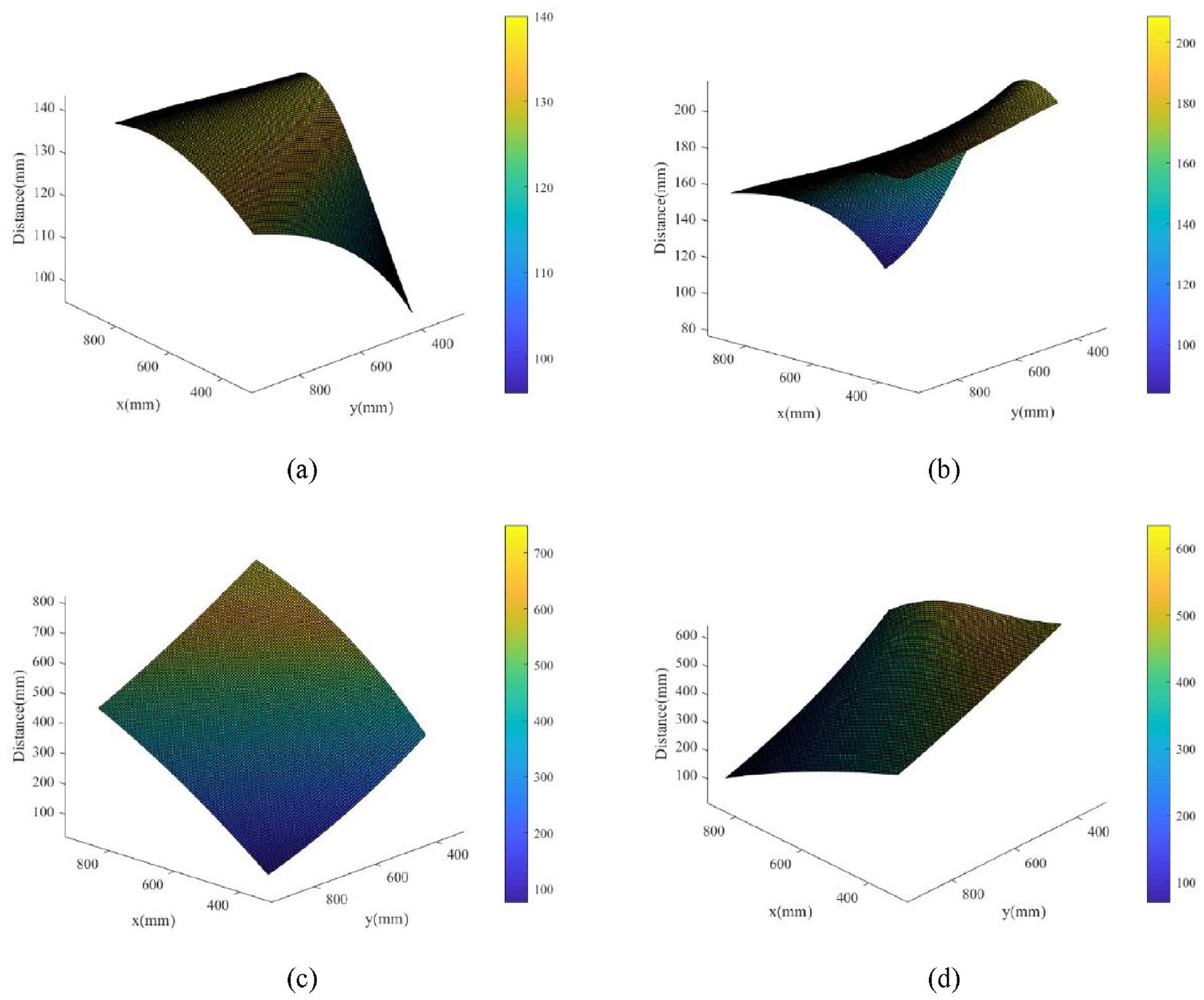
The difference between two Lamb wave travel paths for the any individual scatterer in the region of interest. (a) Path 1 and Path 2, (b) Path 2 and Path 3, (c) Path 3 and Path 4, and (d) Path 3 and Path 5.
The minimum wave packet propagation distance difference between two paths and the position of the corresponding scatterer.
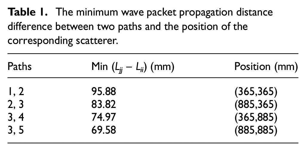
The excitation signal is a three-cycle 60 kHz toneburst and the A0 mode is dominant for the plate thickness. The transmit signal length is 96.26 mm in the distance domain. In this experimental sensor layout, the minimum difference between the wave packet travel distance of any two scattering paths in the first five paths is 69.58 mm, which is greater than 70% of the transmitted signal length. It satisfies the requirements of condition 2 of step 4 in the optimization of transducers position methodology (i.e., for each individual scatterer in the region of interest, min (Ljj – Lii) ≥ 1/2Lext, ii ≤ 3, ii < jj).
In a word, the damage wave packets of the first three paths could be separated and extracted in the experimental layout. Compared with the conventional use of only the direct scattered signal, the approach could acquire three times the amount of damage information with the same experimental conditions.
Experimental results
The response signal is first recorded from the pristine plate as the baseline signal in Figure 8(a) (the blue line). Subsequently, the Lamb wave response is recorded by adding a mass (magnet) to the plate as a damage whose center is located at (500,500) mm in the coordinate system, see the red line in Figure 8(a). The residual signal is obtained by subtracting these two signals, see Figure 8(b). To exploit more damage scattering information in the residual signal for damage imaging, it is necessary to correctly identify each path of scattering wave packets from the residual signal. However, due to the dispersion effect of the Lamb wave, it is difficult to separate the scattered signals of different paths. Hence, the linear mapping dispersion removal algorithm is utilized to remove the dispersion effect. 30 It maps the signal from the time domain to the wavenumber domain where linear wavenumber relation is satisfied, that is,
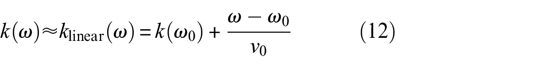
where the center frequency of the excitation signal is 60 kHz. v0 is the group velocity of A0 Lamb wave at 60 kHz. The compensation signal is then converted to the distance domain, see Figure 8(c). The same process is carried out for the atoms in dictionary A. The Hilbert transform is then employed to obtain the corresponding envelope curve, the red dashed line in Figure 8(c). The scattered wave packets of the first three paths in the residual signal are shown in Figure 8(c). To make the damage information of different paths contribute the same weight, the extracted scattered signals of the first three paths of the damage are normalized, see Figure 8(d).
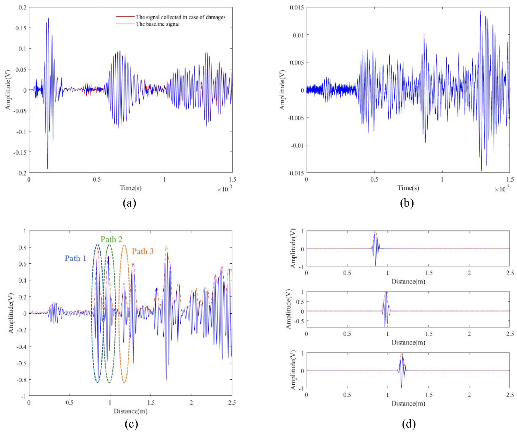
(a) The signal is collected in the absence of the damage and the presence of the damage. (b) The residual signal is obtained by subtracting the baseline signal from the signal collected in case of damages. (c) The compensated signal of (b) and its envelope in the distance domain. (d) The normalized scattered signals of the first three paths are separated from (c).
The imaging region is a square area with dimensions of 520 mm × 520 mm located at the center of the plate, which is discretized into grids of 4 mm × 4 mm in all cases for imaging. In Equation (10), the parameter σ trades off reconstruction fidelity and sparsity. In this experiment, the parameter σ = 0.15||y||2. Figure 9 shows the imaging results of the method with only one transmitter–receiver pair. The areas with high probability values of the image match well with the actual damage areas. In particular, the damage position with the highest probability of the imaging result is (499,503) mm, and the actual damage is centered at (500,500) mm. The location error is 3.16 mm. And the imaging result shows no visible artifacts and a relatively small spot size in the displayed scale, demonstrating the effectiveness of the proposed method.
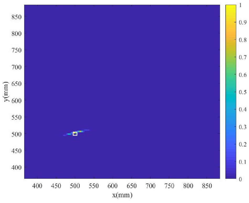
Reconstructed the image for the experiment using the proposed approach. The white square denotes the location of the damage.
Performance analysis
In addition, two sets of experiments are performed to verify the robustness of the proposed method in the whole region of interest. In the first set of experiments, experimental studies are performed at 100 mm intervals in a column of the region of interest. For example: the x-coordinate of the damage (magnets) centers is always 680 mm, and their y-coordinates are 380, 480, 580, 680, 780, 880 mm, respectively. Figure 10(a)–(f) shows the results. The damage location error is shown in Table 2.
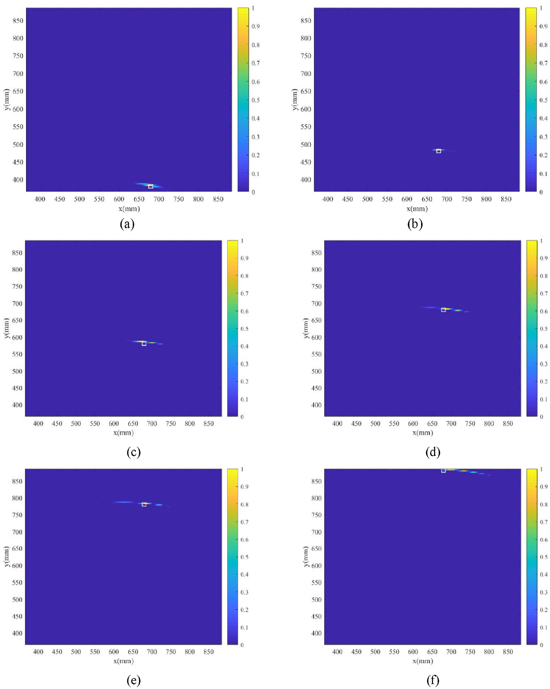
The imaging results were obtained from different damage locations using the proposed method. The damage centers are (a) (680,380), (b) (680,480), (c) (680,580), (d) (680,680), (e) (680,780), and (f) (680,880). The white square denotes the location of the damage.
The actual and detected damage locations in the experiment and the corresponding location errors.
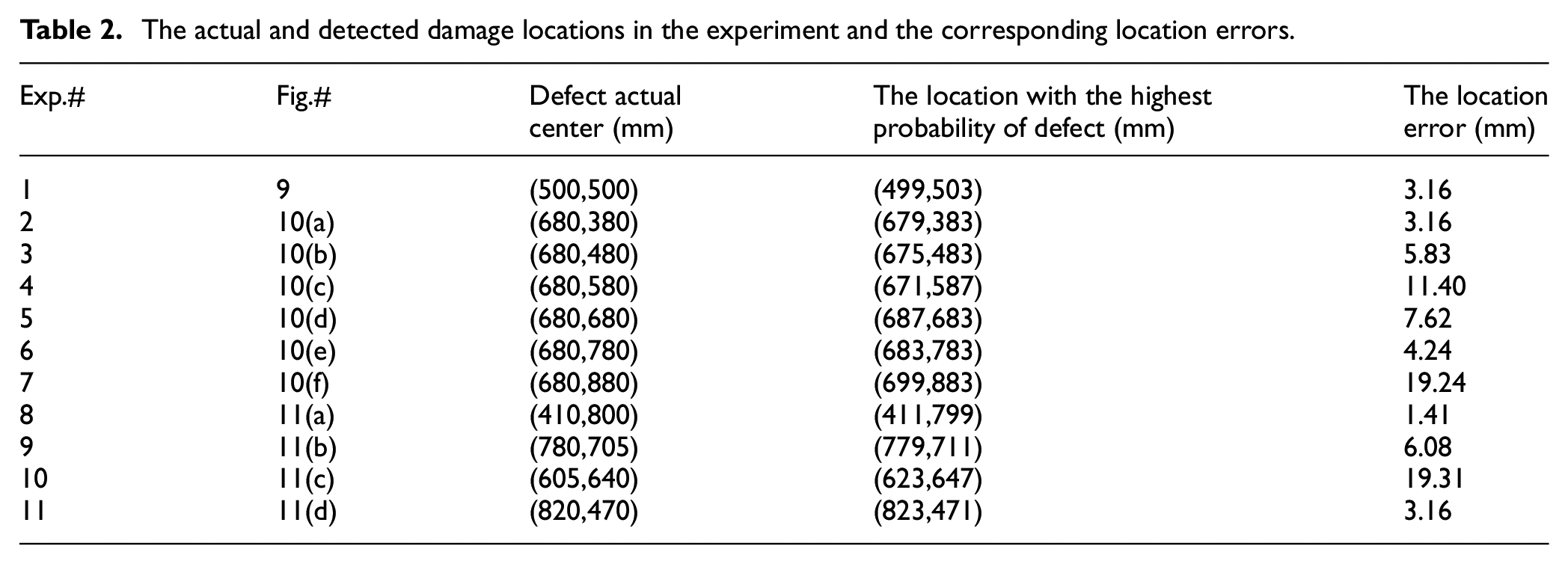
In the second set of experiments, the damages (magnets) are located at any position in the top left, bottom left, top right, bottom right, and middle areas of the region of interest. The result of the experiment in which the damages are in the lower left region has already been shown in Figure 9. The remaining results are shown in Figure 11(a)–(d), respectively. The damage location error is shown in Table 2.

The imaging results obtained from different damage locations using the proposed method. The damage centers are (a) (410,800), (b) (780,705), (c) (605,640), and (d) (820,470). The white square denotes the location of the damage.
In all the experiments, the damage is accurately identified and located with the largest location error being less than 20 mm. They demonstrate the effectiveness and robustness of the multipath Lamb wave imaging method for damage detection. It is noted that in Figure 10(f) and Figure 11(a)–(b), although the location of the maximum probability of detecting damages is in the vicinity of the actual damage and the imaging results have no obvious artifacts, the spot size is relatively large on the displayed scale compared with other experimental results. The reason may be explained as follows. Dictionary A is composed of scattered signals from a single-mode Lamb wave packet propagating at the distance L. If the wave packets travel through the identical distance, the scattered signal is the same. On this basis, the Basis Pursuit De-Noising (BPDN) sparse reconstruction is conducted for the extracted wave packets of each path, the result of which may form an ellipse in the region of interest with the transmitter and receiver as focal points. The transmitter and receiver can be virtual transmitter or receiver obtained due to the edge reflections. The damage scattered signal of the three paths is utilized in the study, and then the three ellipses are formed. The detection position of the damage is at the intersection of the three ellipses. For the damage is far from the transmitter–receiver, the ellipse formed is larger. In the experimental conditions, the three ellipses may be tangential rather than intersecting at this time, which leads to the localized damage area is not concentrated enough and the spot size is large on the displayed scale.
Conclusions
This paper presents a damage sparse imaging method using the multipath-scattered Lamb waves, which realizes the damage location with only one transmitter–receiver pair. Since no significant artifacts are found in the imaging results, the proposed method has been experimentally verified to be sufficiently effective and robust for damage detection. Several conclusions can be drawn as follows:
The multipath-scattered wave packets often tend to overlap, which are intentionally ignored. A strategy for optimization transducer positions is thus established. By optimizing the transducer’s position, the interpretability of the multipath-scattered signal is improved, and the damage multipath-scattered signals can be perfectly separated and exploited.
Exploiting multipath-scattered signals is equivalent to increasing the number of elements in the sensor array. Compared with the conventional direct-path techniques, the proposed method could realize the damage imaging with only one transmitter–receiver pair. Considering these transducers are usually permanently mounted on the structure, the proposed method could further reduce the equipment costs and ensure structural integrity, thus having great potential in the field of SHM.
The imaging results of the present method exhibit few visible artifacts and a relatively small spot size in the displayed scale. Specifically, the largest location error is less than 20 mm.
The transducers’ position optimization in this paper is achieved by fixing one transducer to optimize the position of another transducer, and finally separating the scattered wave packets of the first three paths from the recorded signal. If both transducers are optimized at the same time, perhaps more damage information can be obtained. It is an important and interesting aspect that our future work will focus on.
Footnotes
Declaration of conflicting interests
The author(s) declared no potential conflicts of interest with respect to the research, authorship, and/or publication of this article.
Funding
The author(s) disclosed receipt of the following financial support for the research, authorship, and/or publication of this article: The work is supported by the National Natural Science Foundation of China (Grant No. 52375123 and 52105122), the China Postdoctoral Science Foundation (Grant No. 2021M693882), and the Open Foundation of Henan Key Laboratory of Underwater Intelligent Equipment, which are highly appreciated by the authors.