






Abstract
Advanced aircraft structures are susceptible to hazardous factors such as external impact while in operation. It is crucial to establish aircraft health-monitoring technology that enables online safety status evaluation of composite structures. However, the problem of low accuracy in structural damage localization under working load persists. This study proposes a progressive research methodology that employs the innovative idea of feature-level fusion. The methodology involves active guided wave mechanism analysis, guided wave feature extraction, adaptive compensation, and precise damage localization. An improved active damage localization method oriented by passive real-time strain sensing is proposed. Verification and validation experiments fully verify the feasibility, applicability, and accuracy of the method, achieving damage localization under working load. In essence, through passive to active mapping network at its core, this study has to some extent overcome the bottleneck problem of aircraft damage localization that is unreliable under working load.
Keywords
Introduction
The next generation of aircraft faces a conflict between the demanding service environment and the intelligent requirements of the aircraft, which include critical aspects such as strong robustness, high reliability, and low latency. The resulting safety issues are increasingly impeding the advancements of integrated aircraft design and health management. Among these issues, structural safety takes the utmost priority as catastrophic accidents often occur once structural safety factors come into play. Structural health monitoring (SHM) can determine the structural response online, assess the structural health status in real time, and predict potential damage and failure. Furthermore, timely measures can be taken to ensure the service safety of the aircraft structure.
For SHM system, sensor network, signal acquisition, and processing system form its primary components. Piezoelectric (PZT, PbZrxTi(1-x)O3) sensors,1,2 fiber-optic sensors, 3 strain sensors, 4 and so on are used in sensor networks. Real-time sensing is essential for SHM. In SHM, damage localization is an essential input for subsequent damage quantification and the first warning line for aircraft structural safety. Unlike traditional offline monitoring methods under stable load environments, online damage localization encounters practical challenges of diverse and unpredictable working load states. Therefore, achieving damage location calibration of aircraft structures under working load urgently needs to be addressed as a technical bottleneck.
Research on damage localization can be categorized into two types: one for stable environments and the other for load-disturbed environments. Sensing information used for damage identification includes vibration data, guided wave (GW), and fiber grating signal. The stable environment refers to the offline state where external factors, such as load, temperature, and humidity, can be disregarded. This paper mainly focuses on damage localization under load disturbances and will not discuss further the research on damage localization under stable environments.
To improve damage localization capabilities in harsh service environments, there are currently two methods available—one that is based on modal information and the other that is based on GW signals. The “dynamic fingerprint” method is a representative method for damage localization based on modal information.5,6 SHM through “dynamic fingerprint” detects changes in physical characteristics such as mass, damping, and stiffness of structures due to damage, using the changes in structural modal parameters as “fingerprints” to judge the structure’s health status. While modal signals are inherent characteristics of structures and are not affected by load, they lack the ability to accurately locate damage if the damage state is unknown. Although Colombo et al. 7 attempted to use the inverse finite element method to calibrate dangerous areas of thin-walled structures, the positioning area tends to be broad. In conclusion, the application prospects of relying solely on modal signals for damage localization in aircraft composite structures are not promising.
The GW-based SHM method is sensitive to small damage, has a large monitoring area, and is capable of monitoring a variety of materials. It has broad potential engineering applications.1,8,9 The principle of early GW methods used for health monitoring is to analyze the time-frequency characteristics of GWs after damage, such as signal flight time and energy.10,11 On this basis, methods that utilize PZT array imaging are increasingly being applied. This kind of method aims to detection the impact of damage through multichannel information processing. 12 Recent years, time-reversal phase synthesis imaging methods, delay accumulation imaging methods, and so on have been developed. Representative studies include: (1) Michaels, 13 Ihn and Chang, 14 and Qing et al. 15 have conducted research on the delayed accumulation method, which has been applied in damage imaging of fuel tanks in composite material systems. (2) Wang and Yuan, 16 Wilcox, 10 Wu et al., 17 and Yan et al. 18 conducted research on path imaging methods, which do not require propagation velocity parameters and have developed multiple damage factors in related studies. In the improved research, Choi et al., 19 Zhao et al., 20 Wang et al., 21 and others established cross-correlation damage factors in path imaging with the goal of improving positioning accuracy. (3) Wang et al. 12 and Park et al. 22 studied the basic principles and corresponding practical applications of time-reversal imaging methods. Mei et al. 9 explored the applicability of time-reversal imaging methods in damage monitoring of composites. The author also developed the ATRPS (Alternating Time-Reversal Phase Synthesis) method 23 based on this method and verified its applicability for composite material damage monitoring through numerical simulation and experiments. In summary, this type of method has low requirements for the arrangement of sensing arrays, is relatively simple to use, and benefits from the global propagation characteristics of GW signals, making it advantageous in monitoring large-scale areas.
But these traditional damage imaging methods are mostly aimed at stable load environments. Traditional damage imaging methods are primarily designed for stable load environments and their applicability is severely disrupted under the influence of external loads, exhibiting limitations that restrict their online usage.
To address the issue of damage identification during environmental disturbances, the baseline-free method, environmental compensation method, and uncertainty transfer method have received more attention. 24 The conventional approach of environmental compensation is to extract the characteristics of GW signals in certain environmental states, study the mathematical relationship between environmental parameters and signal characteristics, and then form a model or data-driven compensation model. The current relevant methods focus on the impact of temperature changes. In data-driven methods, researchers25,26 introduce the optimal baseline subtraction (OBS) method. OBS is based on the recognition of baseline signals in the database, in order to obtain the most likely baseline signal at that temperature. To achieve this goal, data-driven methods were established based on data mining techniques, such as mean square deviation, maximum residual amplitude, principal component analysis, singular value decomposition, and independent component analysis. The basis of model-driven methods is an approximate model of the effect of temperature on GW signals, with baseline signal stretching (BSS) being a representative method. In this technology, only one baseline is needed because GW signals are stretched or compressed until they match this universal baseline. The stretching of signals in time or frequency leads to the expansion of wave packets and an extension of arrival time. Therefore, correction is performed in the frequency domain by stretching the frequency axis. Harley and Moura 27 developed three model-driven optimal temperature compensation methods: scale invariant correlation method, iterative scale transformation method, and a combination of the two. By utilizing these tools, the calculation speed of BSS method has been improved. Liu et al. 28 proved that the instantaneous phase difference of GW signals at different temperatures is directly proportional to the temperature difference, and there is a temperature limit range. Based on this compensation approach, Hall and Michaels, 29 Salmanpour et al., 30 and Ostiguy et al. 31 improved the accuracy of delayed accumulation imaging results under changes in environmental temperature. Sun et al., 32 Li et al., 33 and others studied the relationship between GW signal characteristics and temperature through algorithms such as neural networks (NNs). Based on the benchmark signal reconstructed by data-driven models, they applied tomographic imaging methods for experimental verification.
In compensation-related research, the interference of GW signals caused by various nonuniform environmental parameters makes the reference signal no longer the “reference,” and thus the damage identification conducted is no longer reliable. In order to overcome the dependence on reference signals, baseline-free damage imaging methods have been studied. Qiang and Shenfang, 34 Lee et al., 35 and Huan and Li 36 started with adaptive source removal algorithms, frequency dispersion correction, and other methods and extracted damage scattering signals by specially arranging sensors, thereby achieving damage imaging. In addition, some researchers37,38 have gradually approached dynamic probability modeling as a reliable damage diagnosis method under the influence of service environment from the perspective of uncertain model construction. By using dynamic probability modeling to describe the interference caused by environmental factors and suppressing them, signal features that are only sensitive to damage are highlighted, thereby achieving reliable localization of structural damage.
The analysis of three methods for dealing with the impact of environmental factors on GW signals clearly shows the following aspects: (1) Existing environmental compensation methods rely on the predictability of environmental conditions and the density of coverage, which is often difficult to meet in practical engineering applications, especially for the variable workloads, which is less considered. (2) The baseline-free damage imaging method ignores the anisotropy and signal boundary reflection of complex composite material structures, and mostly only combines sparse arrays and verifies them on simple structures. The current research is still difficult to apply to actual aircraft structures. (3) The method of uncertainty transfer relies on the accuracy of constructing uncertainty models, which is difficult to quantitatively implement in complex service environments, and its maturity still needs to be improved.
The purpose of this paper is to achieve damage localization under variable working loads, and the basic idea adopted is derived from the OBS method. It is important to understand the impact of force on GW signals before attempting to compensate. For instance, Gandhi et al. 39 explored the behavior of GW propagation in isotropic media under biaxial uniform stress fields. They determined how laws of dispersion change in relation to different mode frequencies and load combinations. Albakri et al. 40 utilized the acoustoelastic theory to create a model-based stress measurement technique. Shi et al. 41 proposed a baseline-free method for monitoring stress through the propagation of GW in isotropic materials, which proves the mathematical and physical relationship between force load and GW signals. Michaels et al. 42 demonstrated through the use of fatigue test data from wings that the time shift of GW signals caused by load is dependent on the angle and length of the propagation path. Chen and Wilcox 43 studied the analytical relationship between load and GW velocity at arbitrary cross-sections using a finite element analysis approach. Duan and Gan 44 developed a semi-analytical finite element model to simulate GW propagation in each lamina of composite laminates. They analyzed the properties of both forward and backward waves. Although the research is mainly theoretical in nature, it lacks focus on the practical applications of GW. Qiu et al. 45 summarized the effects of load on GW signals as acoustoelastic and electromechanical coupling. They confirmed these effects through simulations and experiments. The authors also quantitatively analyzed how load affects the amplitude and phase of GW signals in isotropic media. Roy et al. 46 proposed a compensation model that addresses the impact of loading on GW signals by considering both phase and amplitude. Zhu et al. 47 analyzed the intricate relationship between GW signals and fatigue cracks in vibrating environments. Wang et al. 48 researched the nonlinear compensation problem of GW signals under the coupling effect of uniformly distributed temperature and static load. In addition, they identified damage in aluminum plates using a probability-weighted imaging method.
Based on these studies, there is currently insufficient analysis on the effect of multidirectional working loads on GW signals for damage identification. In previous research, 49 the author proposed the AATRPS (Adaptive Alternating Time-Reversal Phase Synthesis) method for damage localization under proportional loading. While the proposed method is effective in solving the problem of damage localization under changing load environments, it requires a process of strain monitoring, load identification, GW compensation, and damage imaging. This limits the applicability of the method to multidirectional and nonproportional working loads. Therefore, this paper aims to establish a direct mapping network from real-time monitored passive signals to active GW signals to achieve stable GW compensation under working loads and adaptive damage localization.
This paper will begin with a problem description and theoretical analysis in Section “The problem statement and theoretical background,” followed by a detailed description of the proposed method in Section “The principle and implementation of proposed framework.” Test cases will be conducted to verify the proposed method, as described in Section “Experimental verification and validation.” The final section presents the conclusion.
The problem statement and theoretical background
The problem statement of online damage localization
To address the challenges in damage localization, sensor networks are crucial. The practical conditions of working load can pose issues that must be resolved. Firstly, the measured noise present can impede the time of flight of wave packet. Secondly, the multidirectional stress generated by the working load on the structure can create disturbances that overlap with those caused by damage in the GW signals recorded by the sensors.
Figure 1 displays the typical input–output relationship required for online damage localization. During signal feature extraction, Figure 1(a) shows the disturbance trend of GW signals during proportional loading, while Figure 1(b) shows the results under compound working loads. As seen when comparing Figure 1(a) to (b), it can be seen that the disturbance has changed from ordered and smooth to disordered and chaotic, which could potentially result in inaccurate or incorrect signal feature extraction. Therefore, this paper will focus on solving the following core problem: how to extract hidden damage information online using limited active and passive sensing signals when subjected to the compound working load depicted in Figure 1.
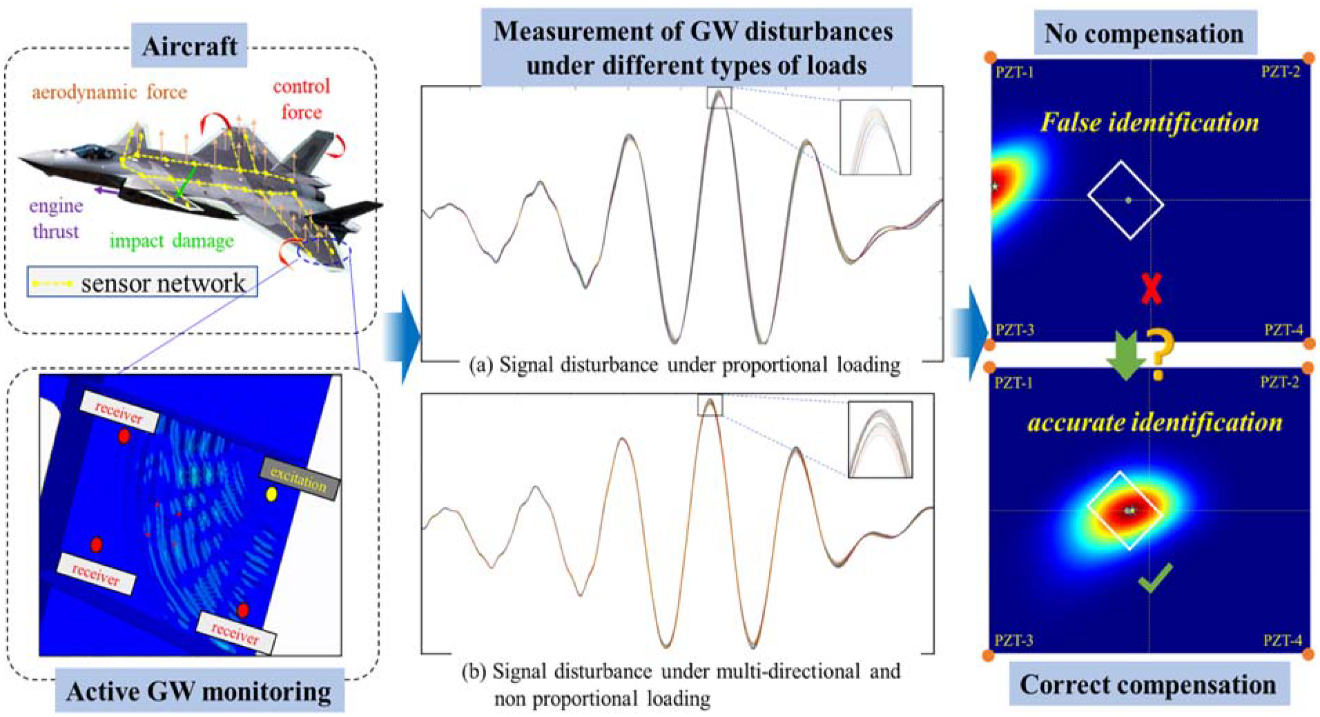
Damage localization under working load: (a) signal disturbance under proportional loading and (b) signal disturbance under multidirectional and nonproportional loading.
Theoretical analysis of key factors
This section will analyze the key factors involved in the propagation process of GW and signal monitoring under load. It is important to note that the objective is not to derive theoretical solutions of GW propagation in composite laminate under complex loads, but to demonstrate the rationality of the proposed method based on theoretical principles and open data. The monitoring of GW in composite laminate can be divided into two main stages: the propagation process within the laminate and signal monitoring at both the excitation and reception ends.
Propagation of GW in composite laminate
When small deformations are present, it can be considered that load changes do not affect the propagation length and attenuation mode of GW. Therefore, at this point, the phase is a more significant factor than the influence of the load on signal energy. The load will cause stress in the structure, and the existence of stress will directly control the dispersion equation of GW propagation. If small deformations are present, the solution of the dispersion equation requires the simultaneous consideration of: (a) the constitutive equation of the material; (b) the mathematical relationship between strain and displacement; (c) wave equation. Therefore, the primary influence of the load on GW propagation will address how to incorporate the stress term caused by load into wave equation.
To simplify the problem, we will analyze the propagation of GW in the x-direction within a lamina, as illustrated in Figure 2. Specifically, we will be examining the wave equation without initial stress, which can be expressed as:
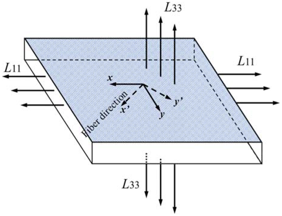
Lamina under bidirectional load. 50
Of these,
The above is the expression of wave equation under the influence of load. It is important to note that the existence of external stress will penetrate the process of wave solution. By combining the method proposed by Cunfu et al., 52 the corresponding dispersion equation can be solved. Mase et al. 53 gave the relationship between the phase velocity of GW propagation of A0 mode and the stress level along the main axis of lamina from numerical analysis. It is concluded that in the region with low frequency-thickness product (about 0.15 MHz-mm below), the variation of GW propagation velocity and load presents a nonlinear monotonic increasing trend. And from an experimental perspective, it has been proven that for composite laminates, even under uniaxial tension, there is a significant nonlinear relationship between the changes in the wave velocity and stress. The change in wave velocity is often associated with the phase shift of the signal. Therefore, phase compensation needs to be taken into account when the load changes, and note that the relationship between the change in phase and stress is not clear. It is nearly impossible to measure stress in multiple directions under a working load, and as a result, the linear relationship between strain and stress is naturally feasible for compensation purposes. In summary, the importance of phase compensation and the feasibility of utilizing strain for phase compensation are obvious.
GW at the excitation and reception
Currently, online monitoring of GW is accomplished by attaching piezoelectric transducers (PZTs) on the structure. The PZT generates high-frequency strain excitation through voltage excitation and inverse piezoelectric effect at the edge of the excitation point on the surface of the structure. The strain is then transmitted through the structure and received by the PZT at the receiving point. Consequently, the voltage is monitored through the piezoelectric effect, and the control of the excitation and reception of GW is achieved by the management of the voltage. The key factors that determine the voltage are the piezoelectric effect and material properties. Roy et al. 54 proposed an analytical expression for the voltage from the excitation terminal (PZT-a) to the receiving terminal (PZT-s).
Among them,
where
where
The strain mode of the structure is denoted as
By combining Equations (6) and (7), it can be concluded that:
By using the strain vector
The principle and implementation of proposed framework
The diverse force loads experienced by aircraft structures can be classified as proportional and nonproportional loads. Therefore, research on structural damage localization methods under operational load should follow the approach of “specificity → generalization” and “verification → validation.” This extends the damage localization method AATRPS 49 under proportional loading to nonproportional loading, which involves multiple stress directions. As a result, the improved adaptive alternating time-reversal phase synthesis (IAATRPS) method has been developed.
The basic principle of IAATRPS framework
The IAATRPS method is based on a basic principle: first, various types of loads are applied to the structure before it is put into use, and a sample set of typical strain response and baseline GW signal characteristics is established. Second, a data model of passive strain and active GW signal features is created based on the idea of feature-level fusion, using NN methods. Finally, the measured strain under service status is used to correct the baseline GW signal and localize structural damage.
The forward denoising and feature extraction of GW
Denoising and feature extraction of GW are the prerequisites of IAATRPS. Note that the set of GW signals collected by
where
where
where
After the decomposition of
where
On the basis of denoising, signal feature extraction can be carried out, that is, the amplitude factor (AM) and phase factor (
where | | refers to the modulus value. Note that the baseline signal of
where
where
The NN-based compensation from passive strain to active GW
In Section “The forward denoising and feature extraction of GW,” we outline the factors that define GW under specific load environments, which serve as the foundation for GW compensation. Given the unique conditions encountered by aircraft, this section proposes an active GW compensation method using passive real-time strain, based on an NN model. Similar to how the brain’s neurons work, the NN is a nonlinear dynamic system that can adaptively learn and map out complex data sets. This makes it valuable for addressing time-domain dynamic GW compensation challenges.
Generalized NN for GW compensation
In this paper, a widely used multilayered NN known as the backpropagation neural network (BPNN) is utilized. Its primary characteristic is the transmission of data (passive strain) in a forward direction and error in a backward direction. Through continuous weight value adjustment, the final output (compensation factors) of the network seeks to approximate the expected output, thereby achieving the intended purpose of compensation. Here, we will only introduce the BPNN construction of AM, and the BPNN construction method corresponding to Δp is the same.
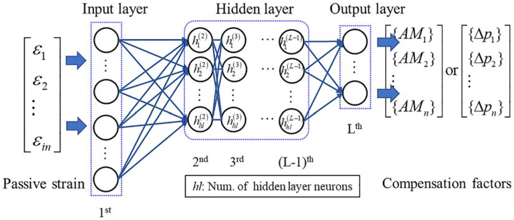
Schematic of BPNN for compensation.
Note that the BPNN is composed of L-layer neurons, in which the first layer is the input layer, the last layer is the output layer, and the other layers are called the hidden layers. Taking channel
The corresponding input is:
The output of each neuron in the l-th hidden layer is:
Let
where
Core of training NN-based compensation model
Suppose we collect ns samples, where the input data in each sample is the measured strain and the output data are the corresponding compensation factors. The primary goal of training a BPNN model is to optimize the input weights and biases of the neurons in each layer, with the aim of minimizing the discrepancy between the NN’s output and the expected output. To accomplish this, we need to solve the derivative of the objective function so as to determine the optimal weights and biases. This process is at the heart of model training. During training, we define the error function
where the subscript sj represents the sj-th element in the vector. Training BPNN is a process of reducing the value of error function
where
Similarly,
Let:
Then,
For layer L − 1,
where:
Then,
Let:
We have:
It can be deduced from the above that the corresponding weights and partial derivatives of neurons in l-th layer
Equation (32) gives the analytical expression of the derivative of the objective function
where
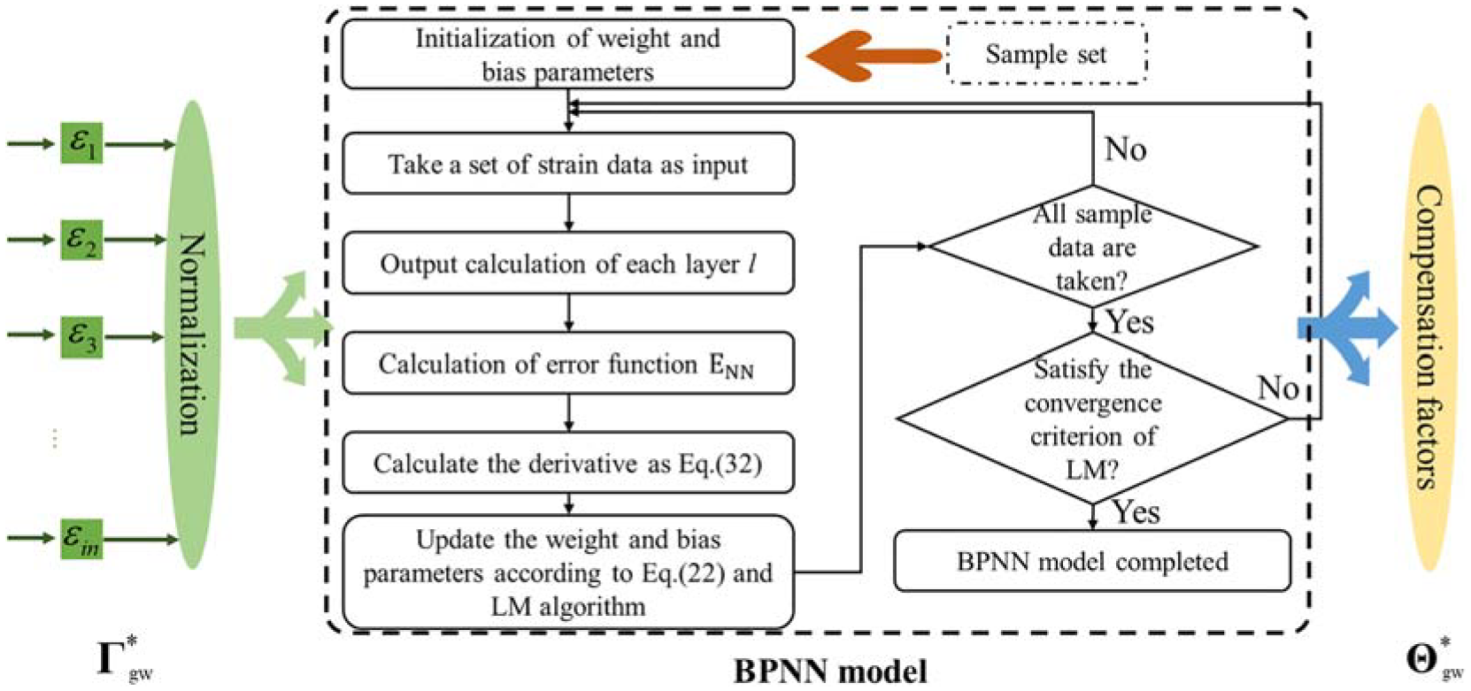
Schematic of training compensation model.
The implementation process of framework
The proposed IAATRPS method framework is presented in Figure 5. The method is comprised of three stages, which are detailed below:
Stage 1: Involve simulating multiple load cases within the load envelope prior to the structure’s deployment. Signal decomposition and correlation screening techniques are employed to create a sample set that consists of phase and AMs for both strain and GW data.
Stage 2: An active GW compensation BPNN model is established using passive strain. To meet convergence and accuracy conditions, sensitivity analysis and LM algorithm are utilized to develop a mapping model that transfers the strain to GW.
Stage 3: The measured strain and GW compensation model are used to reconstruct the baseline GW signal in the present state. Then, damage localization is conducted using the ATRPS method.
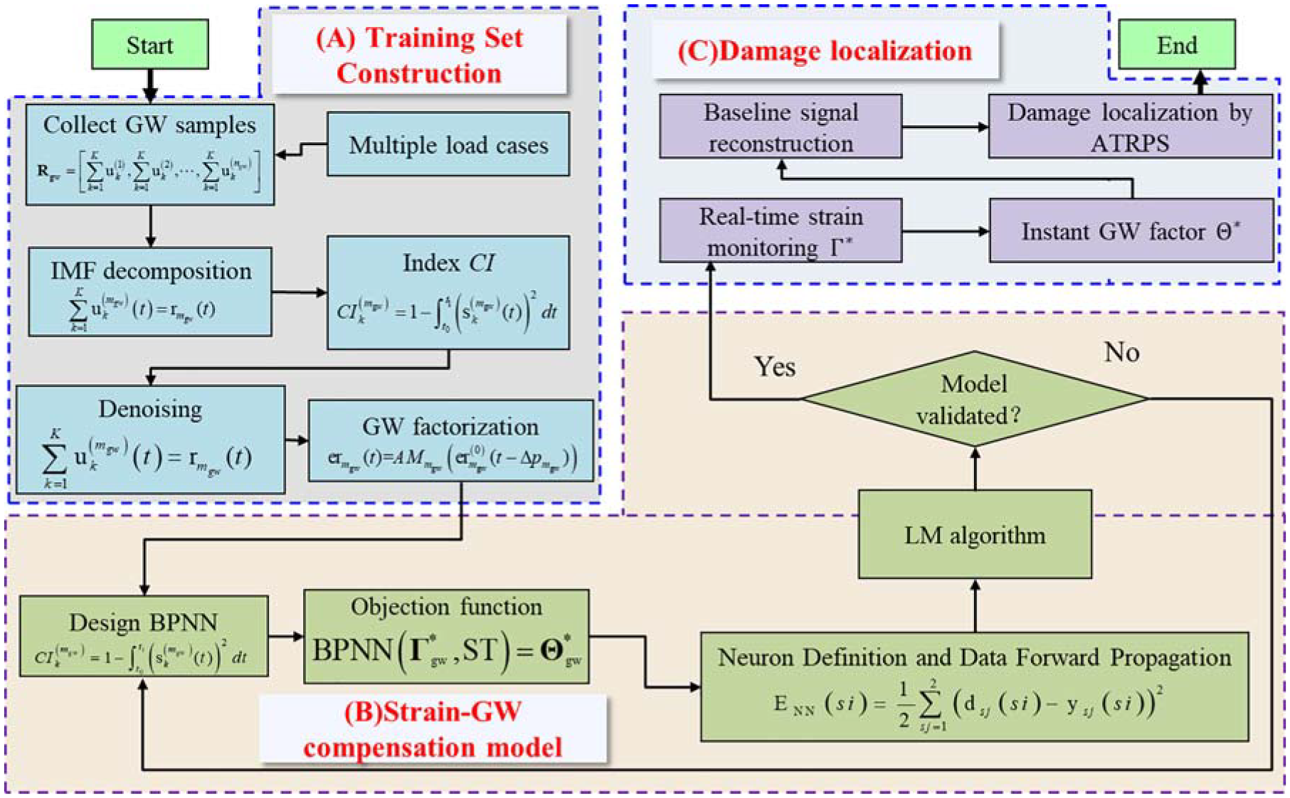
Flowchart of the IAATRPS method.
By sequentially executing the three stages, adaptive compensation for GW signals can be achieved using passive strain data. Thus, accurate monitoring of structural damage caused by accidents in service can be achieved through the idea of the fusion from passive sensing to active sensing.
Experimental verification and validation
In order to confirm the accuracy and practicality of the proposed approach, two experiments were conducted in a sequential manner—one for verification and the other for validation.
Experimental verification
To validate the proposed method, the relationship between GW and strain in composite laminate is confirmed via proportional loading. This section presents an experiment on a single-force transmission path. The schematic diagram of the test piece is shown in Figure 6. The total thickness of the laminate is 2 mm, and the stack sequence is [45°/−45°]4s. Two circular PZTs (with voltage directed vertically) are arranged on both sides of the structure and one strain gauge is placed in the middle. These two PZTs form a single excitation sensing channel, designated CH1. During the entirety of the experiment, the nominal tensile sectional stress is consistently maintained within the range of 0 to 52 MPa. The center frequency of the five-peak sinusoidal excitation signal is set to 54 kHz, generating A0 mode GW at this frequency.
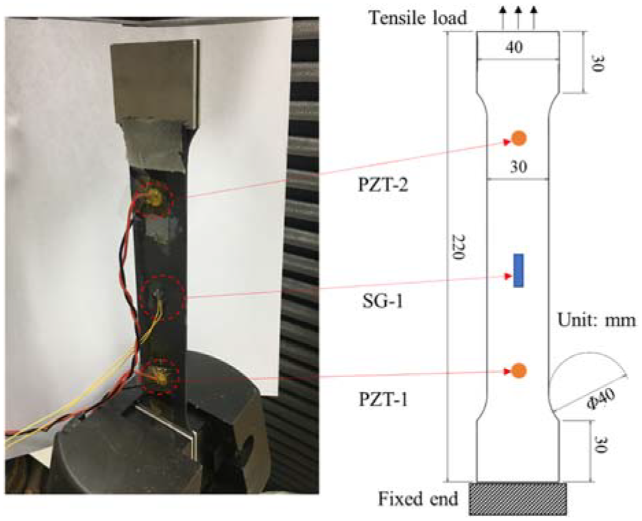
Composite laminate for unidirectional loaded. 49
To begin with, a gradual load application and signal acquisition were conducted. Figure 7(a) illustrates the process of acquiring GW signals and strain data. Simply by observation, it is apparent that a linearly changing strain yields a significant change in the GW signal. Based on the unloaded state, the signal’s amplitude and phase shifts are extracted and compiled into training datasets, which are then utilized to establish two NNs: BAN-1 and BAN-2. These networks take strain readings as input and output GW factors AM and Δp, respectively. The effectiveness of the networks is tested and compared against actual results, as shown in Figure 8(a) and (b), which depict the comparison between the predicted (AM, Δp) values utilizing BAN-1 and BAN-2 and the actual (AM, Δp) values.
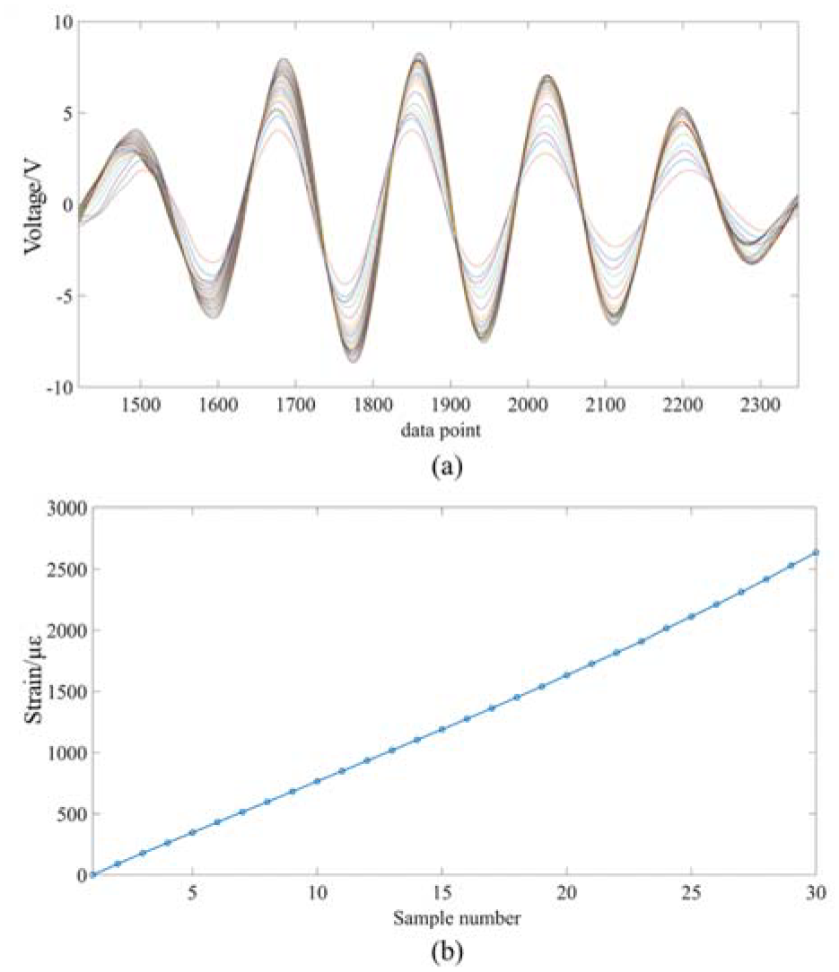
Data collection process: (a) GW signals under different loads and (b) strain sampling process. 49
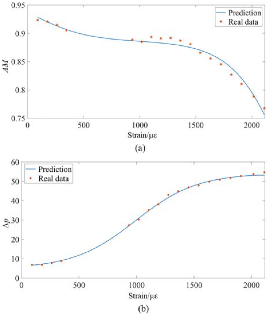
The relationship between AM, Δp, and strain: (a) change of AM with strain and (b) change of Δp with strain.
Based on our experimental results, we have analyzed the phenomenon and its underlying mechanism. Firstly, as shown in Figure 8(a), we observe that the amplitude of CH1 exhibited a nonlinear monotonic trend as the strain increased. We have verified the rationality of this phenomenon using Equations (5) and (6). However, as the strain reached 0.2%, we notice that the amplitude attenuation of the GW exceeded 20%, which proved that false alarms might be triggered if load compensation is ignored during the structure’s service process. Thus, this experiment highlights the importance and necessity of our proposed method.
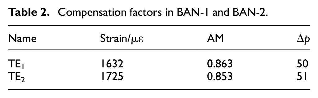
Secondly, as depicted in Figure 8(b), we observe that the phase change of the A0 mode GW showed a nonlinear change with increasing strain. This phase change corresponds to the change in wave velocity, which is consistent with Mase et al.’s 53 findings. They discovered that the wave velocities of transverse and longitudinal waves in composite laminate exhibit nonlinear changes with stress. Finally, we calculate the AM and Δp of BAN-1 and BAN-2 and performed compensation at different strain levels (noted as TE1 and TE2). Our results indicate that the implementation of compensation effectively suppressed the GW signal fluctuation caused by load. We have presented our results in Table 2 and Figures 9 and 10.

Compensation factors in BAN-1 and BAN-2.
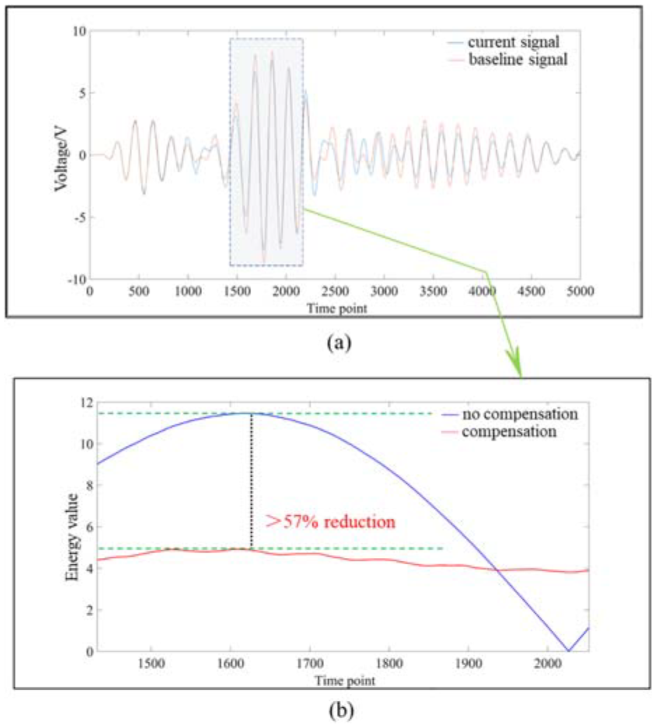
Compensation results of TE1: (a) voltage under 1632 µε and (b) energy of difference signal with and without compensation.
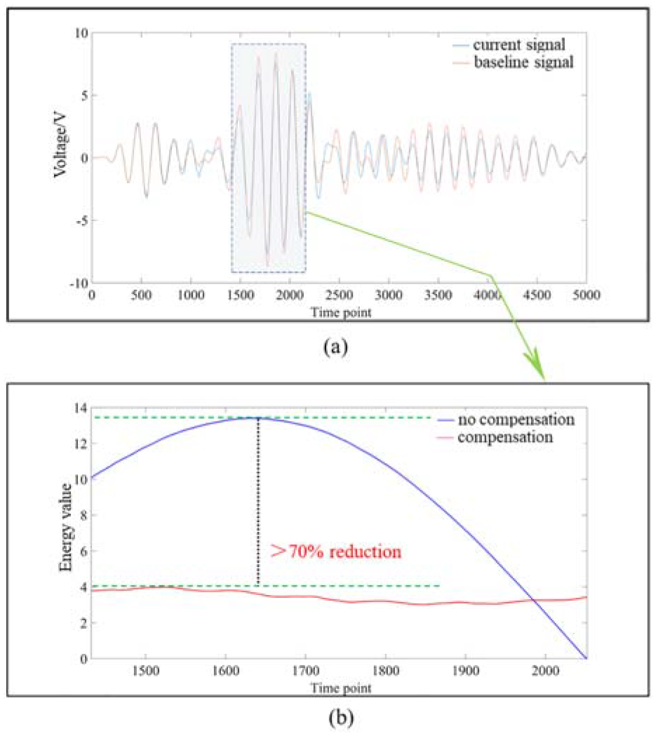
Compensation results of TE2: (a) voltage under 1725 µε and (b) energy of difference signal with and without compensation.
Experimental validation
To validate the IAATRPS method for complex aircraft structures, we design and manufacture a composite wing. The wing components, including the skin, ribs, and beams, are constructed using two-dimensional woven composite materials, while the fixture and loading ends are made of aluminum alloy. T300/QY9512 is used for each lamina’s composite material with a corresponding stack sequence of [0°/45°/0°/45°/0°]. The wing’s dimensions are as follows: a half-span length of 1.5 m, a root chord length of 0.48 m, a tip chord length of 24 cm, and a 1/4 chord sweep angle of 0°. We also use the NACA0012 airfoil. To simulate a nonproportional loading state, we load the sliding rail arbitrarily. The piezoelectric monitoring position is denoted by PZT, and the strain measuring position is denoted by SG, as shown in Figure 11.
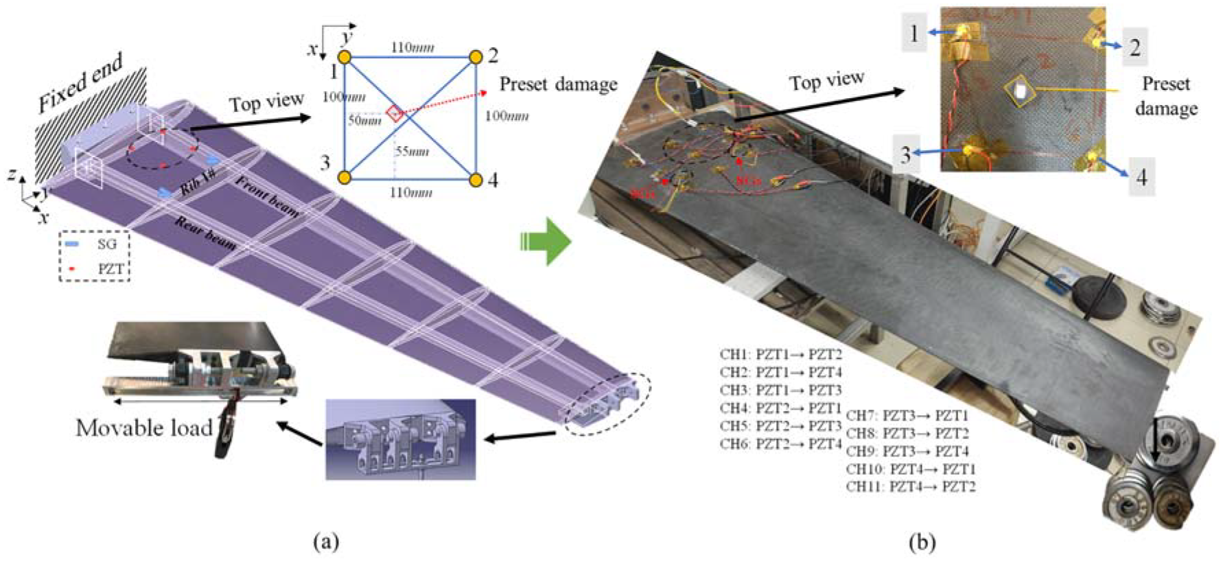
Schematic diagram of the experiment: (a) schematic of the wing and (b) the experiment wing.
During the loading process, we collect 37 sets of GW signals and strain data. Figure 12(a) displays the received signal of CH3, while Figure 12(b) illustrates the strain collection process. We extract the amplitude and phase changes of the GW signals for all samples based on noise filtering and Shannon wavelet transform. These changes are shown in Figure 13(a) and (b). Each channel produces 74 sets of data pairs (37 sets of strain → AM and 37 sets of strain →Δp). Not all channels need compensation due to the impact of data acquisition noise and measurement environment. Therefore, we screen out the channels with significant loading effects from the data.
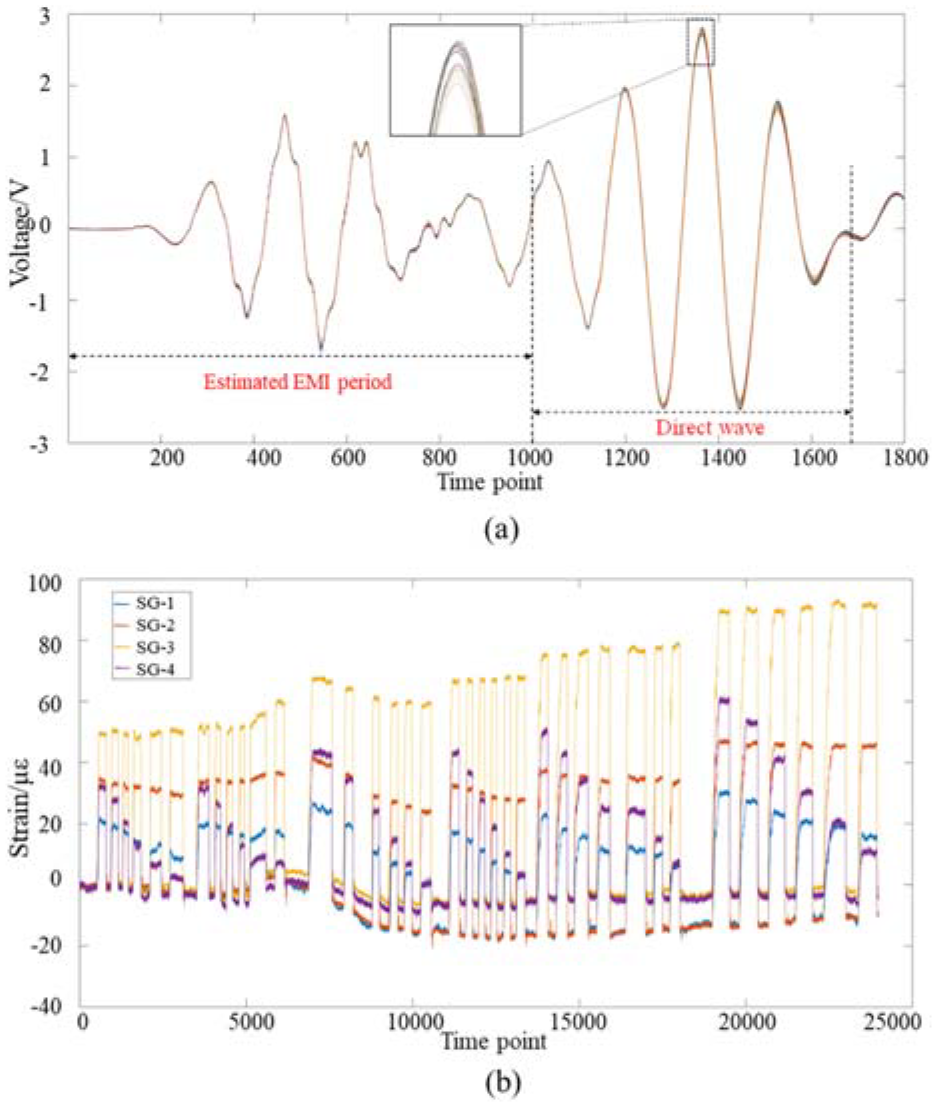
Strain collection history and GW signal of CH3: (a) all signals of CH3 and (b) the measurement process of four SGs.
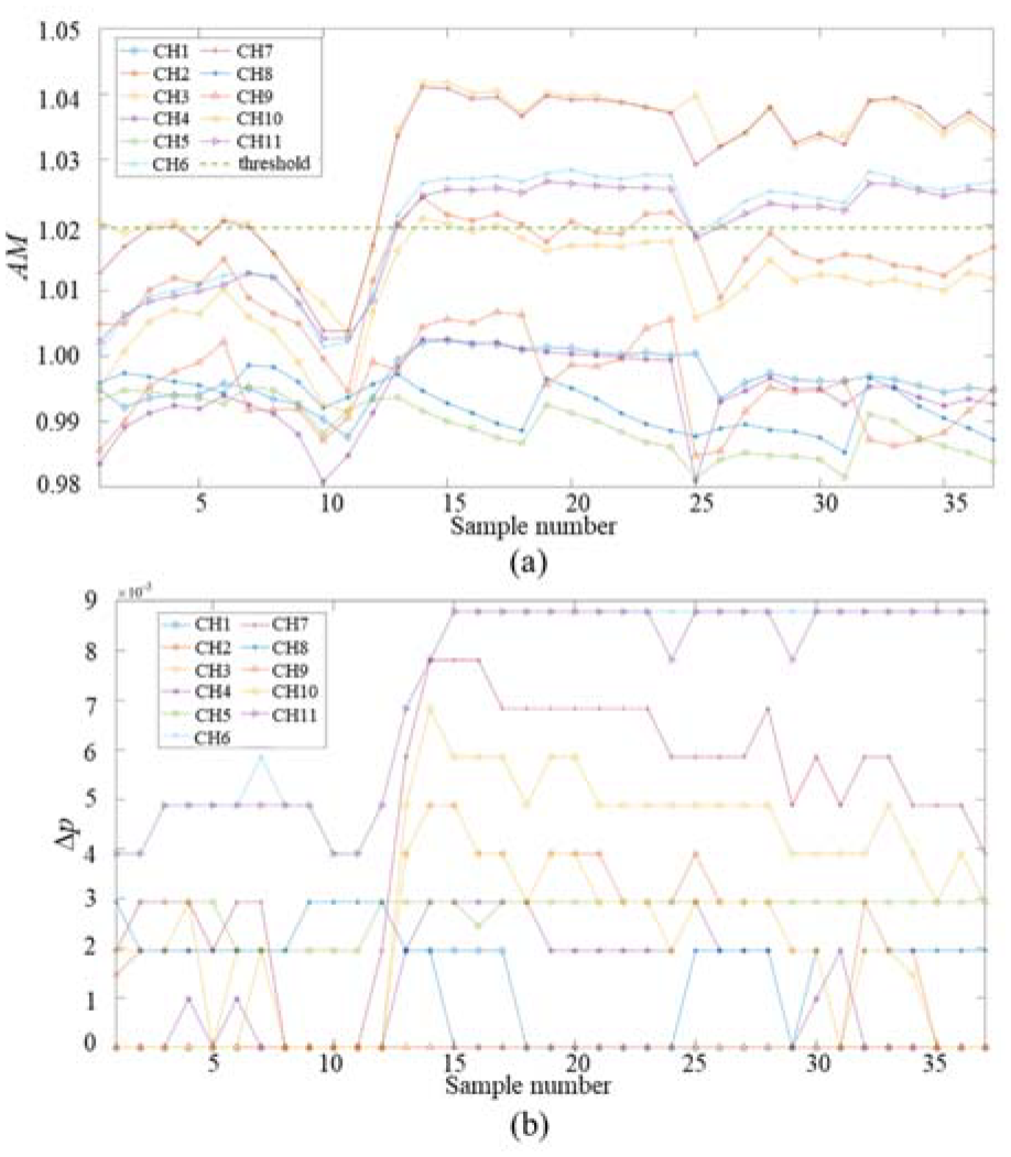
The amplitude and phase factors extracted from each channel: (a) AM factor and (b) Δp factor.
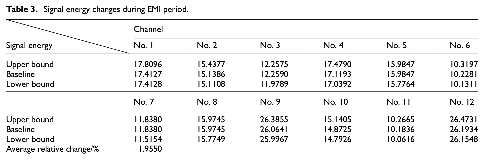
Electromagnetic interference (EMI) is a type of noise that is generated during the process of signal acquisition. From the perspective of the time domain, we can roughly identify the EMI period (spanning approximately 1000 time points) in the time-domain graph of the received signal, primarily based on the emergence of the five-peak waveform in the excitation signal. The amplitude changes that occur during the EMI period in all samples are used to determine whether the signal has been significantly affected by the load. Table 3 displays the upper and lower limits of the amplitude of the EMI signal that has been measured from all sample data. The average signal amplitude change ratio of this segment is 1.9550%. Channels with amplitude fluctuations within this range are considered to be less affected by the load when compared to those that experience greater fluctuations (Figure 13).
Signal energy changes during EMI period.
A total of eight BPNN sets are formed for the four selected channels, denoted as
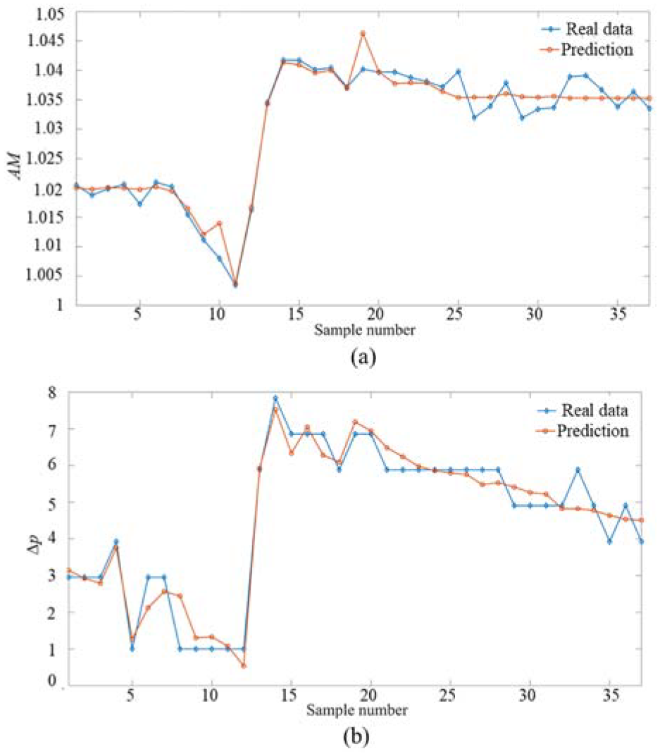
Comparison of predicted data and real data for CH3: (a) AM and (b) Δp.
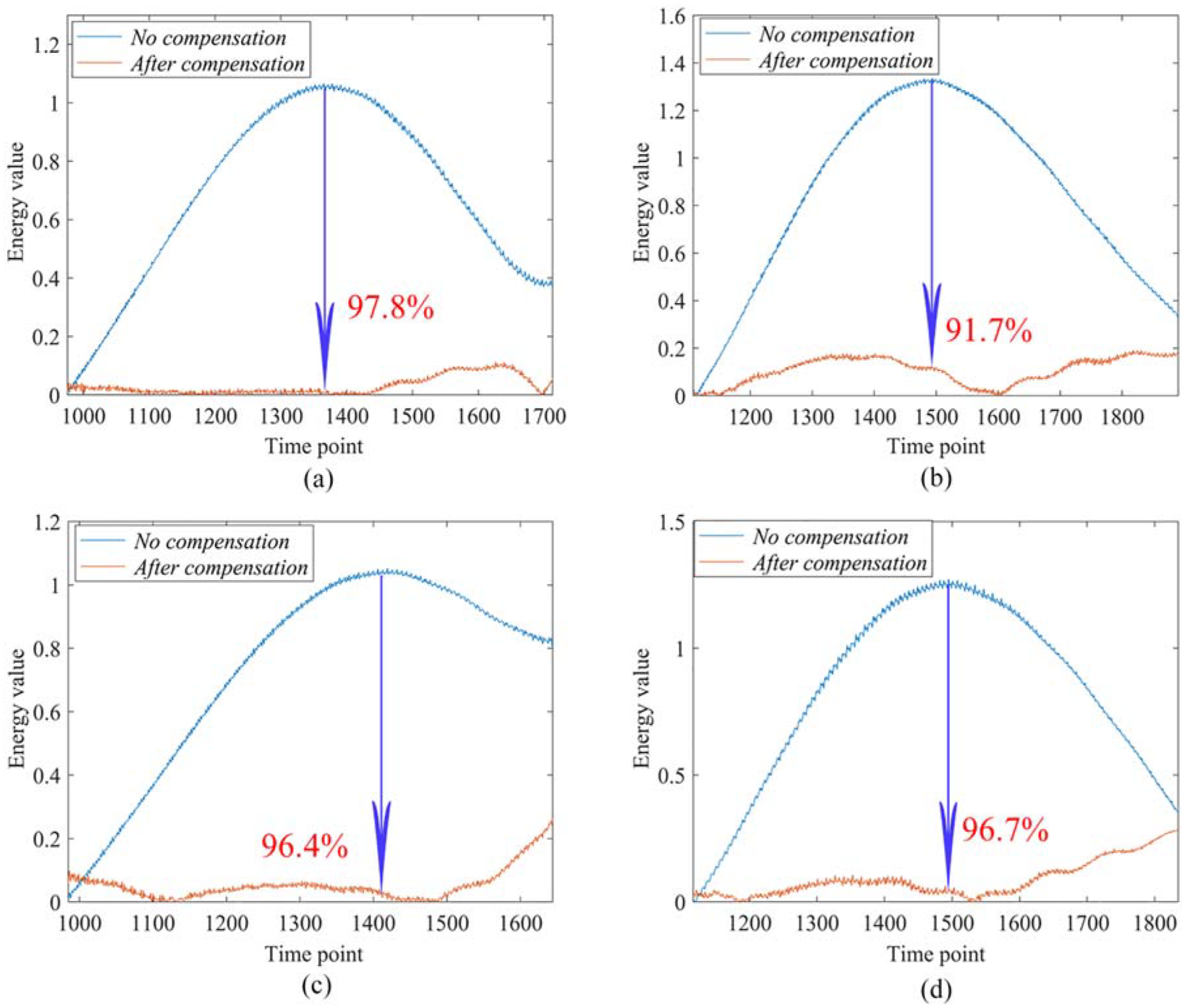
Comparison of direct wave energy before and after compensation: (a) CH3, (b) CH6, (c) CH7, and (d) CH11.
Two types of loading are randomly assigned to the structure. Under each respective loading state, damage is predetermined and strain is measured. Specifically, damage presetting is simulated by dropping weights, as depicted in Figure 16(a). The damage consists of a metal nut (approximately 10 mm diameter) and an absorbing tape, with a total mass of about 15 g, a drop height of about 50 cm, and a drop energy of about 0.0735 J. The damage morphology is shown in the upper right corner of Figure 11. The resulting strain history is presented in Figure 16(b). The caption of Figure 16 holds dual significance. Firstly, it details the preset process of damage, where a combination of a metal nut and absorbing tape is dropped onto the wing’s surface, simulating the predefined damage. Such methods, which are similarly commonly employed for damage presetting,34,38 effectively alter the local damping properties. This specific step is depicted in Figure 16(a). Secondly, the caption underscores the importance of commencing strain collection prior to the occurrence of damage, as shown in Figure 16(b). Furthermore, cases 1 and 2 represent two distinct loading scenarios in the presence of damage. This clarification ensures a comprehensive understanding of the experimental setup and the sequence of events leading to the strain data collection under varying load conditions. Due to the small curvature of the monitoring surface area, it is projected onto the x-y plane to enable analysis. To facilitate damage localization, PZT-3 is used as an excitation source, while the remaining three PZTs are utilized as receivers.
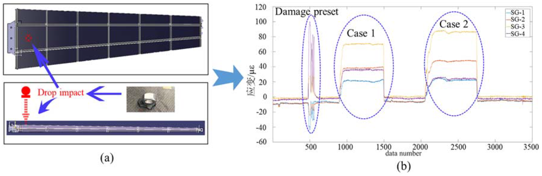
Damage preset and strain collection process: (a) damage preset state and (b) strain acquisition history.
To evaluate the effectiveness of compensation in damage localization, we conduct two separate tests: one without compensation and the other with compensation. The results are presented in Figures 17 and 18, respectively. The white frame refers to the outer contour of the area covered by the damage area, which is marked in the upper right corner of Figure 11. Using the size of the monitoring area as a reference (110 mm length × 100 mm width), we find that the identification error in case 1 is 1.65 mm (with a relative error of less than 1.65%), whereas the identification error in case 2 is 4.96 mm (with a relative error of less than 4.96%). These results demonstrate that the IAATRPS method successfully avoids interference caused by loads and enables precise and reliable identification of damage location. EMI, being an inherent characteristic of electronic device usage, manifests as a similar signal waveform observed during the same time frame as the excitation signal in this experiment. In practical applications, our objective is solely to effectively manage signal interference caused by external loads while minimizing the impact of internal noise. If the energy of a wave packet within the damage scattering signal, obtained through subtraction, is lower than the energy of the difference signal during the EMI period, it can be inferred that the energy of this wave packet is below the system noise threshold and cannot be attributed to damage. Observable structural damage entails a modification in the GW transfer function, resulting in a significant increase in signal energy compared to the noise level of the signal acquisition system. This serves as a prerequisite for damage identification and has been corroborated in Ding et al. 49 Referring to the blue signal curve depicted in Figure 19, a more precise EMI period can be directly pinpointed (amounting to around 900 time points). Furthermore, since the difference signal within the EMI period remains unaffected by external loads or structural damage, for the purpose of visually assessing the compensation effect, we employed a zeroing operation for the EMI period signal during the signal analysis after compensation. Figure 19 compares the damage scattering signals with and without compensation, revealing that the interference signal caused by the load in the uncompensated case exceeds the energy of the EMI period and can easily be mistaken for the first energy peak caused by damage scattering. However, after compensation, the energy of this signal is reduced below that of the EMI period, enabling accurate damage localization.
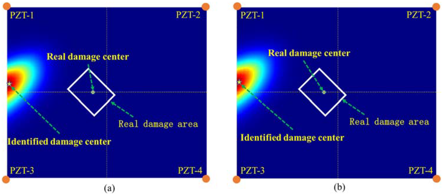
Damage localization results under two cases without considering compensation: (a) Case 1: localization result without compensation and (b) Case 2: localization result without compensation.
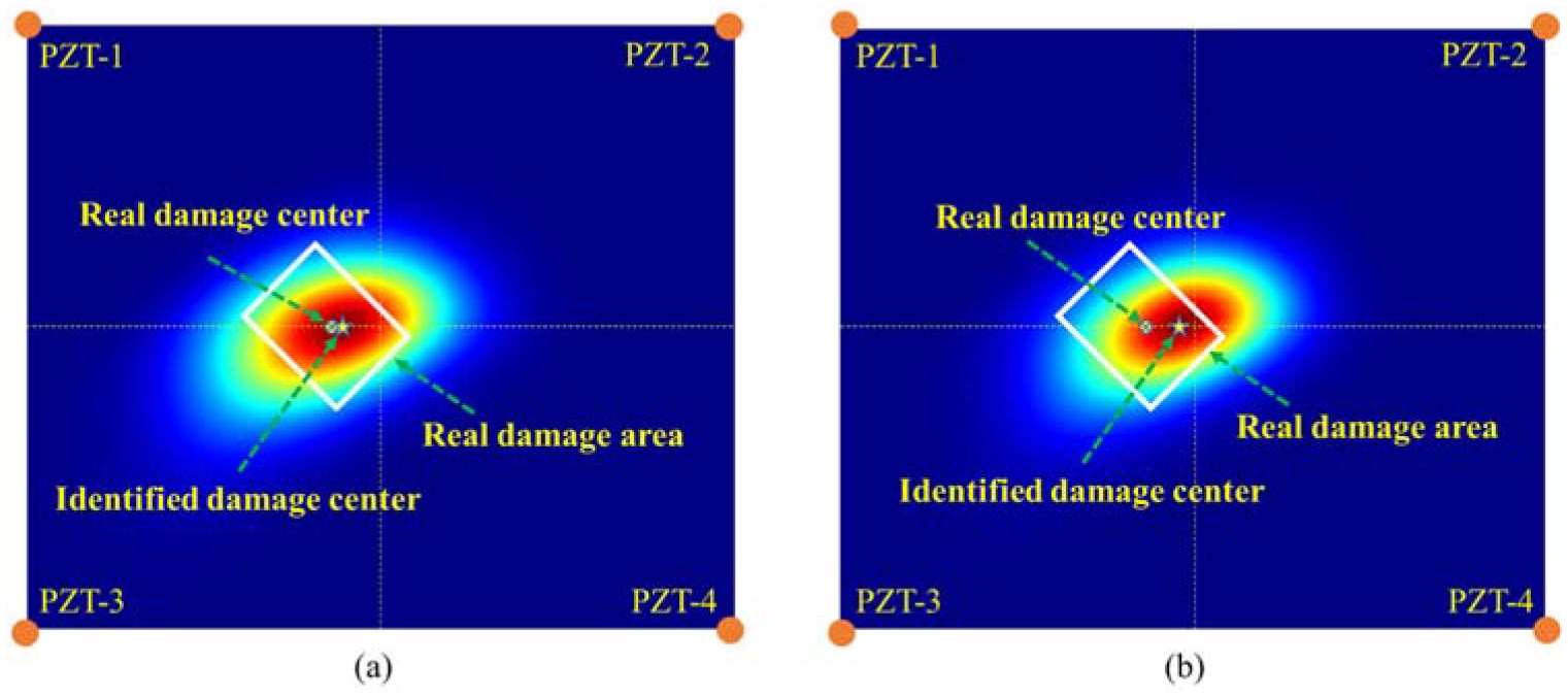
Damage localization results under two cases with considering compensation: (a) Case 1: localization result with compensation and (b) Case 2: localization result with compensation.
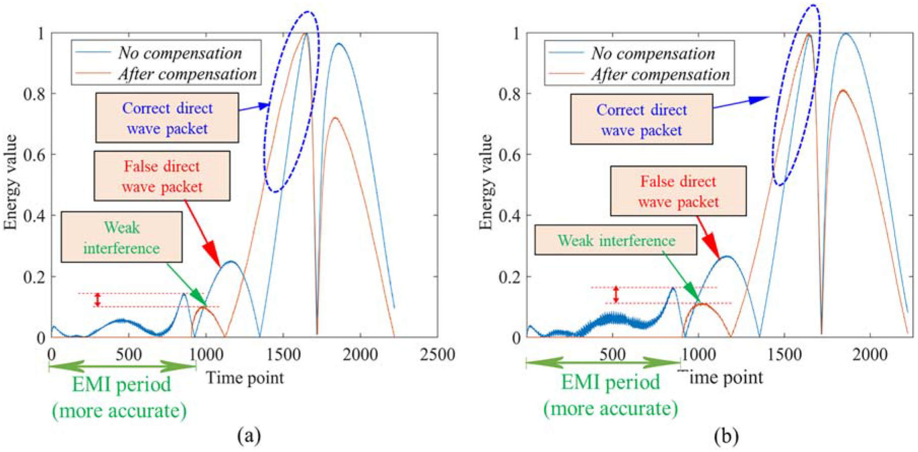
Comparison of damage scattering signals of CH7 with and without compensation: (a) Case 1: comparison of damage scattering signals of CH7 and (b) Case 2: comparison of damage scattering signals of CH7.
Discussion and conclusion
This research paper proposes a compensation model between strain and GW factors to accurately locate damage under working load. The IAATRPS method, which involves fusing passive strain with active GW, is subsequently introduced, and its effectiveness is verified and validated. In conclusion, the study demonstrates a viable solution to precise damage localization.
(1) The impact of load changes on the GW signal cannot be disregarded. The amount by which GW amplitude changes through its respective channel is determined by the degree of compatibility between the force transmission path and the GW channel. In real-world scenarios, changes in load and measurement environment can result in simultaneous alterations in the GW signal. However, through signal factor extraction from the EMI period observed during multiple measurements, changes caused by these two reasons can be separated. This would allow identification of channels that are genuinely and significantly impacted by changes in load.
(2) The adaptive compensation for GW signals reflects the rationality of fusing active and passive information in the process of SHM. Based on this principle, the proposed IAATRPS method can accurately determine whether damage has occurred under working loads and reliably localize the damage.
(3) The IAATRPS method has demonstrated its value through component-level and segment-level experiments. However, this method has some limitations. Firstly, it aims to suppress anomalies in direct wave signals caused by loads without considering changes in signals from other segments over time. While the author’s experiments, as well as those in Ding et al., 49 have not yet resulted in an increased risk of warning and identification, further consideration is needed during the promotion and application stages. Secondly, it is challenging to quantitatively analyze the propagation of GW in a composite laminate from a theoretical perspective. As a result, the proposed method falls into the data-driven category. Therefore, when generating samples, the applied load should cover the types of loads experienced during service, both static and dynamic, to ensure the BPNN has good generalization characteristics.
Footnotes
Appendix A
Declaration of conflicting interests
The author(s) declared no potential conflicts of interest with respect to the research, authorship, and/or publication of this article.
Funding
The author(s) disclosed receipt of the following financial support for the research, authorship, and/or publication of this article: This research is supported by the Defense Industrial Technology Development Program (No. JCKY2019205A006). The authors wish to express their many thanks to the reviewers for their useful and constructive comments. Furthermore, Xuyun Ding wishes to extend his heartfelt gratitude to his fiancée, Chen Xiaojuan, for her unwavering support. Their love has flourished for over 6 years, and together, hand in hand, they strive toward a brighter future.
